EP2166274A1 - Light source device - Google Patents
Light source device Download PDFInfo
- Publication number
- EP2166274A1 EP2166274A1 EP08776969A EP08776969A EP2166274A1 EP 2166274 A1 EP2166274 A1 EP 2166274A1 EP 08776969 A EP08776969 A EP 08776969A EP 08776969 A EP08776969 A EP 08776969A EP 2166274 A1 EP2166274 A1 EP 2166274A1
- Authority
- EP
- European Patent Office
- Prior art keywords
- chassis
- plate
- end parts
- superposed
- illuminant device
- Prior art date
- Legal status (The legal status is an assumption and is not a legal conclusion. Google has not performed a legal analysis and makes no representation as to the accuracy of the status listed.)
- Withdrawn
Links
Images
















Classifications
-
- G—PHYSICS
- G02—OPTICS
- G02F—OPTICAL DEVICES OR ARRANGEMENTS FOR THE CONTROL OF LIGHT BY MODIFICATION OF THE OPTICAL PROPERTIES OF THE MEDIA OF THE ELEMENTS INVOLVED THEREIN; NON-LINEAR OPTICS; FREQUENCY-CHANGING OF LIGHT; OPTICAL LOGIC ELEMENTS; OPTICAL ANALOGUE/DIGITAL CONVERTERS
- G02F1/00—Devices or arrangements for the control of the intensity, colour, phase, polarisation or direction of light arriving from an independent light source, e.g. switching, gating or modulating; Non-linear optics
- G02F1/01—Devices or arrangements for the control of the intensity, colour, phase, polarisation or direction of light arriving from an independent light source, e.g. switching, gating or modulating; Non-linear optics for the control of the intensity, phase, polarisation or colour
- G02F1/13—Devices or arrangements for the control of the intensity, colour, phase, polarisation or direction of light arriving from an independent light source, e.g. switching, gating or modulating; Non-linear optics for the control of the intensity, phase, polarisation or colour based on liquid crystals, e.g. single liquid crystal display cells
- G02F1/133—Constructional arrangements; Operation of liquid crystal cells; Circuit arrangements
- G02F1/1333—Constructional arrangements; Manufacturing methods
- G02F1/1335—Structural association of cells with optical devices, e.g. polarisers or reflectors
- G02F1/1336—Illuminating devices
- G02F1/133602—Direct backlight
- G02F1/133608—Direct backlight including particular frames or supporting means
-
- G—PHYSICS
- G02—OPTICS
- G02F—OPTICAL DEVICES OR ARRANGEMENTS FOR THE CONTROL OF LIGHT BY MODIFICATION OF THE OPTICAL PROPERTIES OF THE MEDIA OF THE ELEMENTS INVOLVED THEREIN; NON-LINEAR OPTICS; FREQUENCY-CHANGING OF LIGHT; OPTICAL LOGIC ELEMENTS; OPTICAL ANALOGUE/DIGITAL CONVERTERS
- G02F1/00—Devices or arrangements for the control of the intensity, colour, phase, polarisation or direction of light arriving from an independent light source, e.g. switching, gating or modulating; Non-linear optics
- G02F1/01—Devices or arrangements for the control of the intensity, colour, phase, polarisation or direction of light arriving from an independent light source, e.g. switching, gating or modulating; Non-linear optics for the control of the intensity, phase, polarisation or colour
- G02F1/13—Devices or arrangements for the control of the intensity, colour, phase, polarisation or direction of light arriving from an independent light source, e.g. switching, gating or modulating; Non-linear optics for the control of the intensity, phase, polarisation or colour based on liquid crystals, e.g. single liquid crystal display cells
- G02F1/133—Constructional arrangements; Operation of liquid crystal cells; Circuit arrangements
- G02F1/1333—Constructional arrangements; Manufacturing methods
- G02F1/133308—Support structures for LCD panels, e.g. frames or bezels
-
- G—PHYSICS
- G02—OPTICS
- G02F—OPTICAL DEVICES OR ARRANGEMENTS FOR THE CONTROL OF LIGHT BY MODIFICATION OF THE OPTICAL PROPERTIES OF THE MEDIA OF THE ELEMENTS INVOLVED THEREIN; NON-LINEAR OPTICS; FREQUENCY-CHANGING OF LIGHT; OPTICAL LOGIC ELEMENTS; OPTICAL ANALOGUE/DIGITAL CONVERTERS
- G02F1/00—Devices or arrangements for the control of the intensity, colour, phase, polarisation or direction of light arriving from an independent light source, e.g. switching, gating or modulating; Non-linear optics
- G02F1/01—Devices or arrangements for the control of the intensity, colour, phase, polarisation or direction of light arriving from an independent light source, e.g. switching, gating or modulating; Non-linear optics for the control of the intensity, phase, polarisation or colour
- G02F1/13—Devices or arrangements for the control of the intensity, colour, phase, polarisation or direction of light arriving from an independent light source, e.g. switching, gating or modulating; Non-linear optics for the control of the intensity, phase, polarisation or colour based on liquid crystals, e.g. single liquid crystal display cells
- G02F1/133—Constructional arrangements; Operation of liquid crystal cells; Circuit arrangements
- G02F1/1333—Constructional arrangements; Manufacturing methods
- G02F1/133308—Support structures for LCD panels, e.g. frames or bezels
- G02F1/133311—Environmental protection, e.g. against dust or humidity
-
- G—PHYSICS
- G02—OPTICS
- G02F—OPTICAL DEVICES OR ARRANGEMENTS FOR THE CONTROL OF LIGHT BY MODIFICATION OF THE OPTICAL PROPERTIES OF THE MEDIA OF THE ELEMENTS INVOLVED THEREIN; NON-LINEAR OPTICS; FREQUENCY-CHANGING OF LIGHT; OPTICAL LOGIC ELEMENTS; OPTICAL ANALOGUE/DIGITAL CONVERTERS
- G02F1/00—Devices or arrangements for the control of the intensity, colour, phase, polarisation or direction of light arriving from an independent light source, e.g. switching, gating or modulating; Non-linear optics
- G02F1/01—Devices or arrangements for the control of the intensity, colour, phase, polarisation or direction of light arriving from an independent light source, e.g. switching, gating or modulating; Non-linear optics for the control of the intensity, phase, polarisation or colour
- G02F1/13—Devices or arrangements for the control of the intensity, colour, phase, polarisation or direction of light arriving from an independent light source, e.g. switching, gating or modulating; Non-linear optics for the control of the intensity, phase, polarisation or colour based on liquid crystals, e.g. single liquid crystal display cells
- G02F1/133—Constructional arrangements; Operation of liquid crystal cells; Circuit arrangements
- G02F1/1333—Constructional arrangements; Manufacturing methods
- G02F1/133308—Support structures for LCD panels, e.g. frames or bezels
- G02F1/133314—Back frames
-
- G—PHYSICS
- G02—OPTICS
- G02F—OPTICAL DEVICES OR ARRANGEMENTS FOR THE CONTROL OF LIGHT BY MODIFICATION OF THE OPTICAL PROPERTIES OF THE MEDIA OF THE ELEMENTS INVOLVED THEREIN; NON-LINEAR OPTICS; FREQUENCY-CHANGING OF LIGHT; OPTICAL LOGIC ELEMENTS; OPTICAL ANALOGUE/DIGITAL CONVERTERS
- G02F1/00—Devices or arrangements for the control of the intensity, colour, phase, polarisation or direction of light arriving from an independent light source, e.g. switching, gating or modulating; Non-linear optics
- G02F1/01—Devices or arrangements for the control of the intensity, colour, phase, polarisation or direction of light arriving from an independent light source, e.g. switching, gating or modulating; Non-linear optics for the control of the intensity, phase, polarisation or colour
- G02F1/13—Devices or arrangements for the control of the intensity, colour, phase, polarisation or direction of light arriving from an independent light source, e.g. switching, gating or modulating; Non-linear optics for the control of the intensity, phase, polarisation or colour based on liquid crystals, e.g. single liquid crystal display cells
- G02F1/133—Constructional arrangements; Operation of liquid crystal cells; Circuit arrangements
- G02F1/1333—Constructional arrangements; Manufacturing methods
- G02F1/133308—Support structures for LCD panels, e.g. frames or bezels
- G02F1/133328—Segmented frames
-
- G—PHYSICS
- G02—OPTICS
- G02F—OPTICAL DEVICES OR ARRANGEMENTS FOR THE CONTROL OF LIGHT BY MODIFICATION OF THE OPTICAL PROPERTIES OF THE MEDIA OF THE ELEMENTS INVOLVED THEREIN; NON-LINEAR OPTICS; FREQUENCY-CHANGING OF LIGHT; OPTICAL LOGIC ELEMENTS; OPTICAL ANALOGUE/DIGITAL CONVERTERS
- G02F2201/00—Constructional arrangements not provided for in groups G02F1/00 - G02F7/00
- G02F2201/50—Protective arrangements
- G02F2201/503—Arrangements improving the resistance to shock
Definitions
- the present invention relates to an illuminant device to be used as a light source of a display device such as a liquid crystal display device.
- an illuminant device is arranged behind a display unit having a display surface which displays an image on a front side thereof.
- the illuminant device comprises, for example, a plurality of lamps having electrodes in both end parts thereof, and a chassis which includes a frame part having a rectangular parallelepiped shape, a lid plate closing an opening portion of the frame part, and a plurality of reinforcement crosspieces mounted to the lid plate with a distance therebetween, and in the chassis, said lamps are juxtaposed (for example, refer to Patent Document 1).
- the lid plate has a rectangular shape corresponding to the frame part, consists of a metal plate such as an aluminum plate and an iron plate, and has a peripheral portion joined to the frame part.
- the chassis has two rectangular cylindrical bodies which have screw insertion holes in peripheral surfaces of end parts thereof and are arranged in parallel with a distance therebetween, and two connecting members which are molded by die-casting so as to have approximately an open square bracket and have convex pieces to be fitted in said two rectangular cylindrical bodies in both ends thereof, and by fitting the convex pieces of the respective connecting members into both end parts of the respective rectangular cylindrical bodies, and screwing male screws inserted into said screw insertion holes into screw holes perforated in said convex pieces, a frame body having a rectangular parallelepiped shape is formed, and a peripheral portion of a lid plate consisting of a metal plate is mounted on the frame body with a plurality of male screws (for example, refer to Patent Document 2).
- a panel thereof becomes larger every year and the illuminant device also becomes larger in response to the increase in the size of the panel.
- the lid plate of the chassis in the illuminant device is formed from a metal plate and the lid plate is formed by a die, a super-sized die for forming a lid-plate is required for an illuminant device to be used for a comparatively large-sized display device, the cost regarding manufacturing efficiency of the lid plate and a lid-plate manufacturing equipment increases, the manufacturing cost of the lid plate and accordingly, the cost of the illuminant device increase, and hence improvement is required.
- the lid plate expands thermally with heat generated by the lamp etc. and a curve, deflection and deformation occur in said lid plate easily.
- the applicant of the present invention has previously developed an illuminant device by constructing a lid plate of said chassis from a plurality of plate bodies juxtaposed along a surface of said lid plate, and connecting members connecting adjacent plate bodies, thereby improving the productivity of the lid plate, reducing the cost of the comparatively large-sized illuminant device, and preventing deflection and deformation by thermal expansion of the lid plate.
- the frame body and the lid plate can be simply formed.
- the frame body formed from a metal plate is generally easy to twist and deform.
- the present invention has been made in view of these circumstances, and a main object thereof is to provide an illuminant device capable of preventing outside dust from entering a chassis from a clearance between end parts of a plurality of juxtaposed plate bodies, and from a clearance between end parts of a plurality of juxtaposed chassis components, and capable of improving a connecting strength of the end parts.
- another object is to provide, by constructing a chassis from a frame body formed of a plurality of frame components connected in a quadrangular shape and a plurality of plate bodies mounted in juxtaposition on said frame body, an illuminant device that permits formation of the chassis by a comparatively small die with better productivity even if the illuminant device is comparatively large-sized, increase in a strength of a comparatively large-sized chassis, and also improvement in the yield.
- An illuminant device is an illuminant device comprising a chassis which has a frame part and a lid plate closing an opening portion of said frame part and in which a plurality of lamps are arranged, characterized in that said lid plate includes a plurality of juxtaposed plate bodies whose end parts are superposed on each other.
- the end parts of the juxtaposed plate bodies are superposed on each other, and thereby preventing outside dust from entering the chassis from a clearance between the end parts of the plate bodies.
- An illuminant device is an illuminant device comprising a chassis in which a plurality of lamps are arranged, characterized in that said chassis includes a plurality of juxtaposed chassis components whose end parts are superposed on each other.
- the end parts of the juxtaposed chassis components are superposed on each other, and thereby preventing outside dust from entering the chassis from a clearance between the end parts of the chassis components.
- An illuminant device is preferred to further comprise a connecting unit connecting said superposed end parts to each other.
- the end parts of the plurality of plate bodies or the plurality of chassis components are superposed on and connected to each other, and thereby improving the connection strength of the plate bodies, and accordingly, the rigidity of the chassis without using a reinforcing member.
- An illuminant device is preferred to be constructed such that one of the superposed end parts is displaced in a direction in which the end parts are superposed.
- a direction in which outside dust enters the chassis can be changed to two directions, and thereby improving the prevention of dust-entering.
- An illuminant device is preferred to be constructed such that the connecting unit has a strip-shaped plate which is bent in a concavo-convex shape in a direction of width thereof, and a mounting member for mounting the strip-shaped plate on the superposed end parts.
- the connecting unit has a strip-shaped plate which is bent in a concavo-convex shape in a direction of width thereof, and a mounting member for mounting the strip-shaped plate on the superposed end parts.
- An illuminant device is preferred to be constructed such that one of said superposed end parts has a cylinder part which projects in a direction in which the end parts are superposed, and is arranged in a concave portion of said strip-shaped plate, said strip-shaped plate has a through hole which penetrates the concave portion, and said mounting member is inserted into the through hole and is fitted in said cylinder part.
- the connection strength can be improved by the fitting of the mounting member, and accordingly the rigidity of the chassis can be further improved.
- An illuminant device is preferred to be constructed such that said superposed end parts have concave parts, respectively, and the concave parts are fitted in each other.
- the concave parts are provided in the superposed end parts themselves and the concave parts are fitted in each other, and thereby the connection strength of the plate bodies or the chassis components, and accordingly the rigidity of the chassis are improved, without use of a reinforcing member and strip-shaped plate.
- An illuminant device is preferred to be constructed such that through holes penetrating said concave parts are provided and a connecting unit is fitted in said through holes.
- the fitting amount of the connecting unit increases without causing the connecting unit such as a male screw to project in the chassis, the flatness in the chassis can be maintained, the connection strength can be improved by the connecting unit, and accordingly the rigidity of the chassis can be improved.
- An illuminant device is preferred to be constructed such that one of said superposed end parts has a concave part and a through hole penetrating the concave part, and the other of said superposed end parts has a cylinder part which projects in a direction in which the end parts are superposed, and is arranged in said concave part, and said connecting unit is inserted into said through hole and is fitted in said cylinder part.
- the connecting unit since the fitting amount of the connecting unit increases without causing the connecting unit such as a male screw to project in the chassis, the flatness in the chassis can be maintained, the connection strength can be improved by the connecting unit, and accordingly the rigidity of the chassis can be improved.
- An illuminant device is an illuminant device comprising a chassis in which a plurality of lamps are arranged, characterized in that said chassis includes a frame body which has a plurality of frame components connected in a quadrangular shape, and a plurality of plate bodies which are mounted in juxtaposition on said frame body.
- the chassis having the frame body and the plate bodies can be formed by a comparatively small die with better productivity, and since the plurality of plate bodies are mounted in juxtaposition on the frame body having the plurality of frame components connected in the quadrangular shape, a strength of the comparatively large-sized chassis can be increased. Moreover, even if a defect occurs in one or some of the plate bodies, it is possible to obtain a chassis by exchanging only the plate body where the defect has occurred, and thereby to improve the yield.
- An illuminant device is preferred to be constructed such that opposing edge portions of the adjacent plate bodies are arranged apart from connecting parts of said frame components in a circumferential direction of said frame body.
- the connecting parts of the frame body where the plurality of frame components are connected in a quadrangular shape, and the opposing edge portions of the adjacent plate bodies are disposed with a distance therebetween in the circumferential direction of the frame body since the connecting parts of the frame body where the plurality of frame components are connected in a quadrangular shape, and the opposing edge portions of the adjacent plate bodies are disposed with a distance therebetween in the circumferential direction of the frame body, the torsion rigidity of the chassis can be improved with a simple structure, and even if the illuminant device is comparatively large-sized, the cost of the illuminant device provided with the chassis having high rigidity can be reduced.
- An illuminant device is preferred to be constructed such that said plate bodies have plate parts and rising pieces which rise from non-opposing edges of the adjacent plate parts, respectively, and said plate bodies are mounted on said frame body so that said rising piece form a frame shape.
- the rising pieces of the plate bodies form a frame shape
- the torsion rigidity of the chassis can be further improved, and even if the illuminant device is comparatively large-sized, the cost of the illuminant device provided with the chassis having high rigidity can be reduced.
- An illuminant device is preferred to be constructed such that said frame components are cylindrical bodies arranged on four sides of said frame body, and in corner portions of the four sides, one of the two adjacent cylindrical bodies has a fitting hole in a peripheral surface which opposes an end of the other cylindrical body, whereas the other cylindrical body has a fitting shaft extending outward beyond the end and fitted in said fitting hole, and further, the illuminant device further comprising escape preventing means for preventing the fitting shaft from escaping from said fitting hole.
- the frame body of the comparatively large-sized chassis can be constructed in a highly accurate quadrangular shape simply. Furthermore, since the connecting state of the two cylindrical bodies is maintained by the escape preventing means, even if the illuminant device is comparatively large-sized, the cost of the illuminant device provided with the chassis having high rigidity can be reduced.
- An illuminant device is preferred to be constructed such that said frame body is arranged outside said rising pieces.
- the plate bodies can be formed by a smaller die with better productivity.
- An illuminant device is preferred to be constructed such that said frame body is arranged inside said rising pieces.
- the optical sheet for diffusing light emitted by the lamps can be supported by the frame body and the frame body serves as a sheet receiving base for supporting the optical sheet, a dedicated sheet receiving base can be removed.
- An illuminant device is preferred to be constructed such that said frame body is arranged outside said plate parts.
- a substrate such as an inverter substrate to be connected to the lamps can be mounted on the frame body apart from the plate body, the structure for mounting the substrate can be simplified, and the workability for mounting the substrate can be improved.
- the end parts of the juxtaposed plate bodies are superposed on each other, and thereby outside dust can be prevented from entering the chassis from a clearance between the end parts of the plate bodies.
- the end parts of the juxtaposed chassis components are superposed on each other, and thereby outside dust can be prevented from entering the chassis from a clearance between the end parts of the chassis components.
- the end parts of the plate bodies or the end parts of the chassis components are superposed on and connected to each other, and thereby the connection strength of the plate bodies and accordingly, the rigidity of the chassis can be improved, without use of a reinforcing member.
- the chassis having the frame body and the plate bodies can be formed by a comparatively small die with better productivity. Furthermore, since the plurality of plate bodies are mounted in juxtaposition on the frame body where the plurality of frame components are connected in the quadrangular shape, the intensity of the comparatively large-sized chassis can be increased. Moreover, even if a defect occurs in one or some of the plate bodies, it is possible to obtain a chassis by exchanging only the plate body where the defect has occurred, and thereby to improve the yield.
- FIG. 1 is a sectional view showing a configuration of an illuminant device according to the present invention incorporated in a display device
- FIG. 2 is a rear view showing a configuration of a chassis of an illuminant device according to the present invention
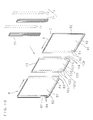
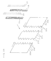
- FIG. 3 is an exploded perspective view showing a configuration of the chassis in which a frame part is omitted
- FIG. 4 is an enlarged sectional view taken along line IV-IV in FIG. 2
- FIG. 5 is an enlarged sectional view where a part of the line IV-IV in FIG. 2 is omitted.
- the illustrated illuminant device is mounted behind a display unit 1 in a thin display device A provided with the display unit 1 having a display surface 1a on a front side thereof and an approximately rectangular parallelepiped shape.
- the illuminant device comprises a chassis B having a frame part 2 and a lid plate 3 and having a box shape with a front side thereof opened, a plurality of lamps 4 which have straight tubular shapes and are juxtaposed with a distance therebetween up and down in the chassis B, a holder holding both end parts of said lamps 4 inside the frame part, a plurality of clips holding intermediate parts of said lamps 4 with respect to the lid plate 3, a reflective sheet 5 which is arranged in the chassis B and reflects light emitted by the lamps 4 to an opening portion side of the chassis B, and an electrical component 6 such as an inverter circuit substrate which is mounted on an outer face of the lid plate 3.
- the lamps 4 are cold cathode tubes or hot cathode tubes having electrodes in both end parts thereof, and the inverter circuit substrate is connected to the electrode of each lamp 4 so that a luminosity thereof is controlled by a pulse width modulation signal.
- the chassis B includes the frame part 2 having a rectangular parallelepiped shape, and the lid plate 3 having a peripheral portion joined to the frame part 2 and closing a back side end of the frame part 2.
- a plurality of screw holes are perforated in the back side end of the frame part 2 with a distance therebetween in a circumferential direction thereof.
- the lid plate 3 is constructed with first to third plate bodies 31, 32, 33 which are juxtaposed along a face of said lid plate 3 in a longitudinal direction of the lamps 4 and connect by a connecting unit 7, and is formed in a rectangular shape corresponding to the frame part 2.
- the first to third plate bodies 31, 32, 33 are constructed by forming an aluminum plate in an approximately rectangular shape, and adjacent end parts thereof are superposed on each other.
- each of the first and second plate bodies 31, 32 a plurality of mounting holes 31a, 32a having annular recesses around edges thereof are perforated with a distance therebetween in a direction in which the plate bodies 31 to 33 are juxtaposed and a direction along ends of said end parts, cylindrical bodies 34 having screw holes are mounted in the mounting holes 31a, 32a, respectively.
- cylindrical bodies 34 After the cylindrical bodies 34 are fitted in the mounting holes 31a, 32a, one ends thereof are fixed by caulking and caulked parts are fitted in said annular recesses.
- insertion holes 31b, 32b for connectors to be connected to the lamps 4 and the inverter circuit substrate are provided in a row in the other end part of each of the first and second plate bodies 31, 32.
- Both end parts of the third plate body 33 are displaced through shoulders 33a, 33a in a plate thickness direction (superposed direction), an end part 31c of the first plate body 31 is superposed on the one end part 33b, and an end part 32c of the second plate body 32 is superposed on the other end part 33c.
- insertion holes 33d where the cylindrical bodies 34 of the first plate body 31 are inserted, respectively, are perforated with a distance therebetween in the juxtaposition direction of the plate bodies 31 to 33 and a direction along an end of the one end part 33b.
- insertion holes 33e where the cylindrical bodies 34 of the second plate body 32 are inserted, respectively, are perforated with a distance therebetween in the juxtaposition direction of the plate bodies 31 to 33 and a direction along an end of the other end part 33c.
- insertion holes 31d, 32d, 33f corresponding to the screw holes are perforated in ends of the first to third plate bodies 31, 32, 33 corresponding to the frame part 2.
- the connecting unit 7 has strip-shaped plates 71 which are superposed on the end parts 33b, 33c of the third plate body 33 and are bent in a concavo-convex shape in a direction of the width thereof, and male screws 72 which are screwed into screw holes of the cylindrical bodies 34 and push and mount the strip-shaped plates 71 on the superposed end parts 31c, 33b, 32c, 33c.
- the male screws 72 constitute a mounting member.
- Each of the strip-shaped plates 71 is bent in a concavo-convex shape with two contact flat surfaces 71a in contact with outer faces of the end parts 33b, 33c and three concave parts 71b which are depressed from edges on both sides of each of the contact flat surfaces 71a, and the two concave parts 71b located on both sides include through holes 71c corresponding to the cylindrical bodies 34 perforated in said superposed direction.
- Each of the through holes 71c has a diameter smaller than that of each cylindrical body 34, and a tip of each cylindrical body 34 is in contact with an inner face of each concave part 71b.
- connection of the first to third plate bodies 31, 32, 33 are provided by juxtaposing the first and second plate bodies 31, 32 having the end parts 31c, 32c where the cylindrical bodies 34 are mounted, with a distance therebetween along the surface of lid plate 3 so that outer faces thereof face upward, arranging the third plate body 33 between the first and second plate bodies 31, 32, inserting the cylindrical bodies 34 of the first plate body 31 into the insertion holes 33d of the one end part 33b of the third plate body 33, inserting the cylindrical bodies 34 of the second plate body 32 into the insertion holes 33e of the other end part 33c of the third plate body 33, then laying the strip-shaped plates 71 on the end parts 33b, 33c of the third plate body 33, and in a condition that the contact flat surfaces 71a of said strip-shaped plates 71 are in contact with the outer faces of the end parts 33b, 33c, inserting the male screws 72 into the through holes 71c perforated in the concave parts 71b of the strip-shaped plates 71, and screwing the male screws into the screw holes
- the connecting causes the contact flat surfaces 71a of strip-shaped plates 71 to push against the end parts 33b, 33c, causes the superposed end parts 31c, 33b and the superposed end parts 32c, 33c to tightly attach to each other, and removes a clearance between the superposed end parts 31c, 33b and a clearance between the superposed end parts 32c, 33c.
- the lid plate 3 formed in this manner is laid on the back end of the frame part 2, and is mounted on the frame part 2 with the male screws which are inserted into the insertion holes 31d, 32d, 33f of the first to third plate bodies 31 to 33 and screwed into the screw holes, and thereby the chassis B having a box shape is formed.
- the contact flat surfaces 71a of the strip-shaped plates 71 connecting the first to third plate bodies 31 to 33 are pushed against the end parts 33b, 33c, the superposed end parts 31c, 33b and the superposed end parts 32c, 33c are tightly attached to each other, and a clearance between the superposed end parts 31c, 33b and a clearance between the superposed end parts 32c, 33c are removed.
- the weight saving of the lid plate 3 can be achieved, the rigidity of the lid plate 3 can be improved, the weight saving of the chassis B can be achieved even if the illuminant device is comparatively large-sized, and also the rigidity of the chassis B can be improved.
- the thermal expansion amount in a longitudinal direction of the lid plate 3 composed of the first to third plate bodies 31, 32, 33 connected to each other by the connecting unit 7, and the thermal expansion amount in a longitudinal direction of a lid plate consisting of one sheet-of aluminum plate are measured at the initial temperature of 20 °C, the temperature of 40 °C at the time of analysis, and hence a temperature difference of 20 °C, the thermal expansion amount of the lid plate 3 composed of the connected first to third plate bodies 31, 32, 33 is 0.687 mm, whereas the thermal expansion amount of the lid plate consisting of one sheet of aluminum plate is 0.701 mm, and thus, the thermal expansion amount can be reduced.
- FIG. 6 is an enlarged sectional view showing a main part in another configuration of the chassis of the illuminant device
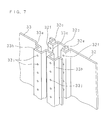
- FIG. 7 is an exploded enlarged perspective view showing a main part in another configuration of the chassis.
- concave parts 31e, 33g which are depressed in the superposed direction are provided in the superposed end parts 31c, 33c of the first and third plate bodies 31, 33, at a plurality of positions disposed with a distance therebetween in the direction in which the plate bodies 31 to 33 are juxtaposed
- concave parts 32e, 33h which are depressed in the superposed direction are provided in the superposed end parts 32c, 33c of the second and third plate bodies 32, 33, at a plurality of positions disposed with a distance therebetween in the direction in which the plate bodies 31 to 33 are juxtaposed
- through holes 31f, 33i, 32f, 33j penetrating in said superposed direction are perforated
- the male screws 72 are inserted into the through holes 33i, 33j of the concave parts 33g, 33h of the third plate body 33, and are screwed into the through holes 31f, 32f of the concave parts 31e, 32e of the first and second plate bodies 31, 32, and thereby the superposed end parts 31c, 33b and the superposed end parts 32c, 33c are connected to each other, respectively.
- the male screws 72 constitute the connecting unit 7 without the strip-shaped plates 71, the assembling workability of the chassis B can be improved.
- the concave parts 31e, 33g, 32e, 33h are provided in the superposed end parts 31c, 33b and the superposed end parts 32c, 33c, respectively, and the concave part 31e is fitted in the concave part 33g and the concave part 32e is fitted in the concave part 33h, respectively, the closer contact between the superposed end parts 31c, 33b and between the superposed end parts 32c, 33c, in other words, improved prevention of dust-entering can be achieved and the connecting strength can be improved without using the strip-shaped plates 71. Since the other structures and functions are the same as those in Embodiment 1, the same codes are used to refer to the same parts and the detailed description thereof is omitted.
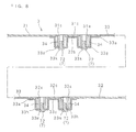
- FIG. 8 is an enlarged sectional view showing a main part in another configuration of the chassis of the illuminant device.
- the concave parts 33g, 33h instead of the concave parts 31e, 33g and the concave parts 32e, 33h provided in the superposed end parts 31c, 33b and the superposed end parts 32c, 33c, respectively, like Embodiment 2, the concave parts 33g, 33h are provided in the end parts 33b, 33c of the third plate body 33, through holes 33k, 33m penetrating in said superposed direction are perforated at a plurality of positions in a longitudinal direction of the concave parts 33g, 33h, and cylindrical bodies 34 (or cylinder parts) projecting in the superposed direction and arranged in the concave parts 33g, 33h are provided in the end parts 31c, 32c of the first and second plate bodies 31, 32. Then the male screws 72 are inserted into the through holes 33k, 33m, and are screwed into the cylindrical bodies 34, thereby connecting
- the end parts 33b, 33c of the third plate body 33 are superposed on the end parts 31c, 32c of the first and second plate bodies 31, 32 juxtaposed with a distance therebetween, so that the cylindrical bodies 34 provided in the end parts 31c, 32c of the first and second plate bodies 31, 32 are arranged in the concave parts 33g, 33h, respectively, and the male screws 72 are inserted into the through holes 33k, 33m of the concave parts 33g, 33h of the third plate body 33 and the male screws are screwed into the cylindrical bodies 34 of the first and second plate bodies 31, 32, so that the superposed end parts 31c, 33b and the superposed end parts 32c, 33c are connected to each other, respectively.
- the male screws 72 constitute the connecting unit 7 without the strip-shaped plates 71
- the assembling workability of the chassis B can be improved.
- the concave parts 33g, 33h are provided in one of the superposed end parts 31c, 33b and one of the superposed end parts 32c, 33c, the connection strength can be improved without use of the strip-shaped plates 71. Since the other structures and functions are the same as those in Embodiments 1 and 2, the same codes are used to refer to the same parts and the detailed description thereof is omitted.
- FIG. 9 is a perspective view showing another configuration of the chassis of the illuminant device
- FIG. 10 is an exploded perspective view showing another configuration of the chassis
- FIG. 11 is an enlarged sectional view showing another configuration of the chassis.
- the chassis C instead of constituting the lid plate 3 of the chassis B having the frame part 2 and the lid plate 3 from the plurality of plate bodies 31, 32, 33, like Embodiments 1 to 3, the chassis C itself is formed from first to third chassis components 8, 9, 10, adjacent end parts 8a, 10a of the chassis components 8, 10 and adjacent end parts 9a, 10b of the chassis components 9, 10 are superposed on each other, respectively, the superposed end parts 8a, 10a and the superposed end parts 9a, 10b are connected to each other by a connecting unit 7 provided with strip-shaped plates 71 and male screws 72, respectively.
- the chassis C has an approximately rectangular shape, and comprises first and second chassis components 8, 9 having first to third plate parts 81, 91,101 juxtaposed in the longitudinal direction of the lamps 4 and three bent pieces 82, 92 bent toward an interior side from three edges of each of the first and second plate parts 81, 91 arranged on both sides, a third chassis component 10 having two bent pieces 102 bent toward an interior side from two edges of the third plate part 101 arranged in the center, and strip-shaped plates 71 and male screws 72 connecting the superposed end parts 8a, 10a of the first and third chassis components 8, 10 and the superposed end parts 9a, 10b of the second and third chassis components 9, 10, respectively, so that the bent pieces 82, 92,102 of the chassis components 8, 9, 10 forms a frame shape.
- a plurality of mounting holes 83, 93 having annular recesses around edges thereof are perforated with a distance therebetween in a direction in which the plate bodies 81, 91,101 are juxtaposed and a direction along ends of said end parts, and the cylindrical bodies 34 having screw holes are mounted in the mounting holes 83, 93, respectively.
- the cylindrical bodies 34 are fitted in the mounting holes 83, 93, one ends thereof are fixed by caulking and caulked parts are fitted in said annular recesses.
- insertion holes 84, 94 for connectors to be connected to the lamps 4 and an inverter circuit substrate are provided in a row in the other end parts of the first and second plate parts 81, 91, respectively.
- the end parts 10a, 10b of the third plate part 101 are displaced through shoulders 101a, 101a in a plate thickness direction (superposed direction), the end part 8a of the first plate body 81 is superposed on the one end part 10a, and the end part 9a of the second plate body 91 is superposed on the other end part 10b.
- insertion holes 103 where the cylindrical bodies 34 of the first plate part 81 are inserted, respectively, are perforated with a distance therebetween in the juxtaposition direction of the plate parts 81, 91, 101 and a direction along an end of the one end part 10a
- insertion holes 104 where the cylindrical bodies 34 of the second plate part 91 are inserted, respectively, are perforated with a distance therebetween in the juxtaposition direction of the plate parts 81, 91,101 and a direction along an end of the other end part 10b.
- the connecting unit 7 has strip-shaped plates 71 which are superposed on the end parts 10a, 10b of the third plate part 101 and are bent in a concavo-convex shape in a direction of width thereof, and male screws 72 which are screwed into the screw holes of the cylindrical bodies 34 and push and mount the strip-shaped plates 71 on the superposed end parts 8a, 10a, 9a, 10b.
- the male screws 72 constitute a mounting member.
- Each of the strip-shaped plates 71 is bent in a concavo-convex shape with two contact flat surfaces 71a in contact with outer faces of the end parts 10a, 10b, and three concave parts 71b which are depressed from edges on both sides of each of the contact flat surfaces 71a, and through holes 71c corresponding to the cylindrical bodies 34 are perforated in said superposed direction in the two concave parts 71b located on both sides.
- Each of the through holes 71c has a diameter smaller than that of each of the cylindrical bodies 34, and a tip of each of the cylindrical bodies 34 is in contact with an inner face of each of the concave parts 71b.
- the first to third chassis components 8, 9, 10 are connected by the following steps of: juxtaposing the first and second chassis components 8, 9 having the end parts 8a, 9a where the cylindrical bodies 34 are mounted, with a distance therebetween so that the plate parts 81, 91 face upward; arranging the third chassis component 10 between the first and second chassis components 8, 9; inserting the cylindrical bodies 34 of the first chassis component 8 into the insertion holes 103 of the one end part 10a of the third chassis component 10; inserting the cylindrical bodies 34 of the second chassis component 9 into the insertion holes 104 of the other end part 10b of the third chassis component 10; laying the strip-shaped plates 71 on the end parts 10a, 10b of the third chassis component 10, respectively; and then in a condition that the contact flat surfaces 71a of said strip-shaped plates 71 are in contact with the outer faces of the end parts 10a, 10b, inserting the male screws 72 into the through holes 71c perforated in the concave parts 71b of the strip-shaped plates 71; and screwing the male screws into the screw
- the connecting causes the contact flat surfaces 71a of the strip-shaped plates 71 to push against the end parts 10a, 10b, causes the superposed end parts 8a, 10a and the superposed end parts 9a, 10b to tightly attach to each other, and removes a clearance between the superposed end parts 8a, 10a and a clearance between the superposed end parts 9a, 10b.
- the chassis C since the end parts of the first and second chassis components 8, 9 consisting of aluminum plates are superposed on and connected to the end parts of the third chassis component 10 consisting of an aluminum plate by the strip-shaped plates 71 and male screws 72, respectively, the weight saving of the chassis C can be achieved even if the illuminant device is comparatively large-sized, and also the rigidity of the chassis C can be improved. Since the other structures and functions are the same as those in Embodiments 1 to 3, the same codes are used to refer to the same parts and the detailed description thereof is omitted.
- FIG. 12 is a front view showing a configuration of a thin display device provided with the illuminant device according to the present invention
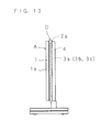
- FIG. 13 is a side view showing the configuration of the thin display device provided with the illuminant device
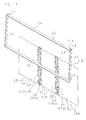
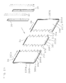
- FIG. 14 is an exploded perspective view showing a configuration of a chassis
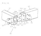
- FIG. 15 is a front view showing the configuration of the chassis.
- the illustrated illuminant device D is mounted on a rear side of a display unit 1 in a thin display device A provided with the display unit 1 having a display surface 1a on a front side thereof and an approximately rectangular parallelepiped shape.
- the illuminant device comprises a chassis E having a quadrangular frame part 2a and a plurality of plate bodies 3a, 3b, 3c which close the back side end of the frame body 2a and having a box shape with the front side thereof opening, a plurality of rod-shaped lamps 4 juxtaposed with a distance therebetween up and down in the chassis E, a holder holding both end parts of said lamps 4, a plurality of clips holding intermediate parts of said lamps 4 with respect to the plate bodies 3a, 3b, 3c, a reflective sheet which is arranged in the chassis E and reflects light emitted by the lamps 4 to an opening portion side of the chassis E, and an electrical component such as an inverter circuit substrate mounted on outer faces of the plate bodies 3a, 3b, 3c.
- the lamps 4 are cold cathode tubes having electrodes in both end parts thereof, and the inverter circuit substrate is connected to the electrode of each lamp 4, and controls a luminosity by a pulse width modulation signal.
- FIG. 16 is an exploded perspective view showing the configuration of the frame body 2a of the chassis E
- FIG. 17 is a sectional view showing the configuration of the frame body 2a of the chassis E
- FIG. 18 is a perspective view showing a corner portion in the configuration of the frame body 2a of the chassis E
- FIG. 19 is a sectional view taken along line IXX-IXX in FIG. 18 .
- the frame body 2a of the chassis E comprises two first rectangular cylindrical bodies 21, 21 which have a quadrangular shape in cross section and oppose to each other in parallel with a distance therebetween, and two second rectangular cylindrical bodies 22, 22 which have a quadrangular shape in cross section and are connected to both ends of the first rectangular cylindrical bodies 21, 21, and a plurality of screw holes 21a, 22a are perforated with a distance therebetween in a longitudinal direction thereof on one of the side surfaces of shorter sides of each of the first and second rectangular cylindrical bodies 21, 22.
- the first and second rectangular cylindrical bodies 21, 22 constitute frame components and cylindrical bodies.
- each of the first rectangular cylindrical bodies 21, 21 includes two fitting holes 21b, 21b penetrating one side surface of a longer side thereof and juxtaposed with a distance therebetween toward the shorter sides, and two insertion holes 21c, 21c penetrating the other side surface of the longer side at positions facing the fitting holes 21b, 21b and having diameters smaller than those of the fitting holes 21b, 21b.
- each of the second rectangular cylindrical bodies 22, 22 includes a fit-in member 23 fitted and fixed into each of said rectangular cylindrical bodies 22, 22, two fitting shafts 24, 24 which are fixed to said fit-in member 23 and are fitted in the fitting holes 21b, 21b, respectively, and two through holes 22b, 22b penetrating the one side surface of the longer side and juxtaposed with a distance therebetween toward the shorter sides.
- Each of the fit-in members 23 has a rectangular shape, closes an end of each of the second rectangular cylindrical bodies 22, 22, and includes an outer plate part 23b having two insertion holes 23a, 23a penetrating in a longitudinal direction of the rectangular cylindrical bodies 22, 22, and two inner plate parts 23c, 23c arranged continuing to longer sides of the outer plate part 23b.
- Two screw holes 23d, 23d are perforated in one inner plate part 23c at positions corresponding to the through holes 22b, 22b, and two headed male screws 25, 25 to be inserted in the through holes 22b, 22b are screwed into the screw holes 23d, 23d, and thereby the fit-in members 23 are fixed in the second rectangular cylindrical body 22, 22.
- the fitting shafts 24, 24 respectively have screw holes 24a, 24a in central portions thereof, consist of circular cylinder bodies having a diameter slightly smaller than an inside diameter of each of the fitting holes 21b, 21b, and have a length in which end faces on the tip side are in contact with the inner surfaces (the other side surfaces of the longer sides) of the first rectangular cylindrical bodies 21, 21.
- the fitting shafts 24, 24 are fixed to an outer face of the outer plate part 23b by the screwing into the screw holes 24a, 24a of headed male screws 26, 26 inserted into the insertion holes 23a, 23a from an interior of the outer plate part 23b.
- Headed male screws 27, 27 inserted into the insertion holes 21c, 21c of the first rectangular cylindrical bodies 21, 21 are screwed into the screw holes 24a and 24a, and thereby preventing the fitting shafts 24, 24 from escaping from the fitting holes 21b, 21b.
- the male screws 27, 27 constitute escape preventing means.
- the fitting holes 21b, 21b and insertion holes 21c, 21c are perforated, and the fit-in members 23 to which the fitting shafts 24, 24 are fixed are fixed by the male screws 25, 25 to the other end parts of the first rectangular cylindrical bodies 21, 21.
- the fitting holes 21b, 21b and the insertion holes 21c, 21c are perforated in the peripheral surfaces of the end parts of the second rectangular cylindrical bodies 22, 22 other than the end parts thereof to which the fit-in members 23 where the fitting shafts 24, 24 are fixed are fixed by the male screws 25, 25.
- the frame body 2a constituted as mentioned above, four sides are formed by the two first rectangular cylindrical bodies 21, 21 which oppose with a distance therebetween and the two second rectangular cylindrical bodies 22, 22 connected to the both ends of the first rectangular cylindrical bodies 21, 21, and each of the corner portions of the four sides is connected by the fitting holes 21b, 21b and the fitting shafts 24, 24 fitted in the fitting holes 21b, 21b, and the male screws 27, 27 prevent the fitting shafts 24, 24 from escaping.
- the fitting shafts 24, 24 are fixed to each of the fit-in members 23, and each of the fit-in members 23 is fitted and fixed into one end part of each of the second rectangular cylindrical bodies 22, 22 and one end part of each of the first rectangular cylindrical bodies 21, 21.
- the plate bodies 3a, 3b, 3c are juxtaposed and mounted on the frame body 2a with male screws 20 screwed into the screw holes 21a, 22a of the first and second rectangular cylindrical bodies 21, 22.
- FIG. 20 is an exploded perspective view showing the configuration of the plate bodies 3a, 3b, 3c of the chassis E with which the illuminant device is provided.
- the plate bodies 3a, 3b, 3c have an approximately rectangular shape corresponding to the frame body 2a, and are juxtaposed in the longitudinal direction of the first rectangular cylindrical bodies 21, 21 and the longitudinal direction of the lamps 4.
- a plurality of pin holes 35a, 36a, 37a are perforated along the edge portions.
- the opposing edge portions are connected to each other by two connecting members 38, 38.
- a plurality of insertion holes 35b, 36b, 37b are perforated along the non-opposing edge portions, corresponding to the screw holes 21a, 22a of the first and second rectangular cylindrical bodies 21, 22.
- the plate bodies 3a, 3b, 3c are mounted on the frame body 2a by the screwing into the screw holes 21a, 22a of the male screws 20 inserted in the insertion holes 35b, 36b, 37b.
- the edge portions of the plate bodies 3a, 3b, 3c which oppose mutually have concavities and convexities, and when the plate bodies 3a, 3b, 3c are juxtaposed, the concavities are engaged with the convexities, respectively.
- the pin holes 35a, 36a, 37a are perforated in the concavities.
- the connecting members 38 consist of strip-shaped plates having a plurality of concavo-concave streaks and made of a columnar iron plate etc., and has a length corresponding to each of widths of the plate bodies 3a, 3b, 3c. Moreover, a plurality of pin holes are perforated on both side parts in a direction of width thereof, corresponding to the pin holes 35a, 36a, 37a.
- the plate bodies 3a, 3b, 3c are juxtaposed on the back side end of the frame body 2a, to be specific, on one of the side surfaces of the shorter sides of each of the first and second rectangular cylindrical bodies 21, 22, the male screws 20 are inserted into the insertion holes 35b, 36b, 37b perforated in the peripheral portion corresponding to the frame body 2a, and the male screws 20 are screwed into the screw holes 21a, 22a of the rectangular cylindrical bodies 21, 22, and thereby the plate bodies 3a, 3b, 3c are fixed to the frame body 2a.
- the connecting members 38, 38 are laid on the edge portions of the plate bodies 3a, 3b, 3c which oppose mutually, and pins 39 are fitted through the pin holes of the connecting members 38, 38 in the pin holes 35a, 36a, 37a of the plate bodies 3a, 3b, 3c, and thereby the plate bodies 3a, 3b, 3c are connected to each other.
- the both ends in the longitudinal direction of the connecting members 38, 38 are fixed to the rectangular cylindrical bodies 22, 22 with male screws, and thereby fixing strength of the plate bodies 3a, 3b, 3c with respect to the frame body 2a can be increased.
- the plate bodies 3a, 3b, 3c Since the opposing edge portions of the plate bodies 3a, 3b, 3c are arranged apart from the connecting parts (corner portions of the frame body) of the rectangular cylindrical bodies 21, 22 in the circumferential direction of the frame body 2a as shown in FIGS. 14 and 15 , the plate bodies 3a, 3b, 3c fixed to the frame body 2a can further improve the torsion rigidity of the chassis E.
- FIG. 21 is a perspective view showing another configuration of the chassis E of the illuminant device.
- the fitting holes 21b, 21b and insertion holes 21c, 21c are perforated in peripheral surfaces of both end parts of the first rectangular cylindrical bodies 21, 21 arranged in parallel with a distance therebetween.
- the fit-in members 23 to which the fitting shafts 24, 24 are fixed are fixed to both end parts of the second rectangular cylindrical bodies 22, 22 by the male screws 25, 25.
- the end parts of the first and second rectangular cylindrical bodies 21, 22 are connected to each other by the male screws 27, 27 screwed from the insertion holes 21c, 21c into the screw holes 24a, 24a of the fitting shafts 24, 24.
- FIG. 22 is an exploded perspective view showing another configuration of the chassis E of the illuminant device
- FIG. 23 is an exploded perspective view showing another configuration of the plate bodies 3a, 3b, 3c of the chassis E.
- the plate bodies 3a, 3b, 3c instead of making the plate bodies 3a, 3b, 3c of the chassis E flat like Embodiment 5, the plate bodies 3a, 3b, 3c have plate parts 30a, 30b, 30c and rising pieces 300a, 300b, 300c rising from non-opposing edges of the plate parts 30a, 30b, 30c, and the plate bodies 3a, 3b, 3c are mounted on the frame body 2a so that the rising pieces 300a, 300b, 300c form a frame shape.
- the plate body 3c arranged at a central portion of the frame body 2a has the rising pieces 300c, 300c rising from the two non-opposing edges, and the plate bodies 3a, 3b arranged on both sides of the frame body 2a have the rising pieces 300a, 300b rising from the three non-opposing edges, and flanges 300d, 300d, 300d extending outward are provided in top parts of the rising pieces 300a, 300b, 300c.
- a plurality of insertion holes 35c, 36c, 37c are perforated in at least either the rising pieces 300a, 300b, 300c or the flanges 300d, respectively.
- screw holes 21a, 22a are perforated in at least one or the other side surface of each of the longer sides of the first and second rectangular cylindrical bodies 21, 22 and one or the other side surface of each of the- shorter sides thereof, corresponding to the insertion holes 35c, 36c, 37c of the rising pieces 300a, 300b, 300c or the flange 300d, respectively.
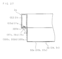
- FIGS. 24 to 27 are sectional views showing the configuration of embodiment 7 of the chassis E.
- the rising pieces 300a, 300b, 300c form a frame shape, and the plate bodies 3a, 3b, 3c are mounted on the frame body 2a.
- the frame body 2a is arranged outside the rising pieces 300a, 300b, 300c, and the plate bodies 3a, 3b, 3c are mounted on the frame body 2a by the male screws 20 inserted into the insertion holes 35c, 36c, 37c perforated in at least either the rising pieces 300a, 300b, 300c or the flanges 300d and screwed into the screw holes 21a, 22a.
- the frame body 2a is arranged inside the rising pieces 300a, 300b, 300c, and the plate bodies 3a, 3b, 3c are mounted on the frame body 2a by the male screws 20 inserted into the insertion holes 35c, 36c, 37c perforated in the rising pieces 300a, 300b, 300c, and screwed into the screw holes 21a, 22a.
- the frame body 2a is arranged outside a peripheral portion of the plate parts 30a, 30b, 30c, and the plate parts 30a, 30b, 30c are mounted on the frame body 2a.
- the plurality of insertion holes 35c, 36c, 37c are perforated in the peripheral portion of the plate parts 30a, 30b, 30c
- the plurality of screw holes 21a, 22a are perforated in the one of the side surfaces of the shorter sides of each of the first and second rectangular cylindrical bodies 21, 22, and the plate bodies 3a, 3b, 3c are mounted on the frame body 2a by the male screws 20 inserted into the insertion holes 35c, 36c, 37c and screwed into the screw holes 21a, 22a.
- the embodiment shown in FIG. 26 may be constructed with at least one of the configurations of FIGS. 24 and 25 combined therewith.
- the frame body 2a is arranged outside the flanges 300d, and the plate bodies 3a, 3b, 3c are mounted on the frame body 2a by the male screws 20 inserted into the insertion holes 35c, 36c, 37c perforated in the flanges 300d and screwed into the screw holes 21a, 22a.
- the embodiment shown in FIG. 27 may be constructed with at least one of the configurations of FIGS. 24 to 26 combined therewith.
- the frame body 2a since the opposing edges of the plate bodies 3a, 3b, 3c are arranged apart from the connecting parts of the rectangular cylindrical bodies 21, 22 in the circumferential direction of the frame body 2a, the torsion rigidity of the chassis E can be further improved. Moreover, in the configuration where the frame body 2a is arranged inside the rising pieces 300a, 300b, 300c as shown in FIG. 25 , since a peripheral portion of an optical sheet can be laid on the shorter sides of the rectangular cylindrical bodies 21, 22 in the frame body 2a, the frame body 2a serves as a sheet receiving base for supporting the optical sheet, and a dedicated sheet receiving base is not required.
- FIG. 28 is an exploded perspective view showing a main part in another configuration of the chassis E of the illuminant device.
- the two fitting shafts 24, 24 provided in one end part of each of the second rectangular cylindrical bodies 22, 22 and one end part of each of the first rectangular cylindrical bodies 21, 21 have different cross sections in a direction orthogonal to an axial direction of the fitting shafts, in other words, a fitting shaft 24b having a circular cylindrical shape of a larger diameter and a fitting shaft 24c having a circular cylindrical shape of a smaller diameter are juxtaposed.
- the fitting holes 21b, 21b provided in one end part of each of the first rectangular cylindrical bodies 21, 21 and one end part of each of the second rectangular cylindrical bodies 22, 22 have different diameters corresponding to the diameters of the fitting shafts 24b, 24c, in other words, a fitting hole of the larger diameter and a fitting hole of the smaller diameter are perforated.
- the first and second rectangular cylindrical bodies 21, 22 can be oriented, and the first and second rectangular cylindrical bodies 21, 22 can be arranged correctly at appropriate positions, and thereby improving the assembling workability of the frame body 2a. Since the other structures and functions are the same as those in Embodiments 5 to 7, the same codes are used to refer to the same parts and the detailed description thereof is omitted.
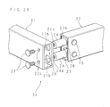
- FIG. 29 is an exploded perspective view showing a main part in another configuration of the chassis E of the illuminant device.
- the frame body 2a of the chassis E comprises the two fitting holes 21b, 21b and the fitting shafts 24, 24 like Embodiment 5, and in addition, a positioning projecting portion 28 for determining a position of each of the first and second rectangular cylindrical bodies 21, 22 is provided in the outer plate part 23b of the fit-in member 23, and a positioning recess portion 29 in which the positioning projecting portion 28 is to be fitted is provided in the peripheral surface of the one end part of the first rectangular cylindrical body 21 and the peripheral surface of one end part of the second rectangular cylindrical body 22.
- the positioning projecting portion 28 projects at a position displaced from the fitting shafts 24, 24, and the positioning recess portion 29 is perforated at a position displaced from the fitting holes 21b, 21b.
- the fitting shafts 24, 24 can be fitted in the fitting holes 21b, 21b only in a case where the positioning projecting portion 28 is fitted in the positioning recess portion 29 when the corner portions of four sides are connected to form the frame body 2a, the first and second rectangular cylindrical bodies 21, 22 can be oriented, and the first and second rectangular cylindrical bodies 21, 22 can be arranged correctly at appropriate positions, and thereby improving the assembling workability of the frame body 2a. Since the other structures and functions are the same as those in Embodiments 5 to 7, the same codes are used to refer to the same parts and the detailed description thereof is omitted.
- the lid plate 3 comprises the first to third juxtaposed plate bodies 31, 32, 33 which are made of aluminum in the chassis B of the embodiments explained above
- the lid plate 3 may be constructed with a plurality of connected plate bodies whose linear expansion coefficients differ from each other.
- the first and second plate bodies 31, 32 may be made of aluminum having a linear expansion coefficient of 2.3 ⁇ 10 -5
- the third plate body 33 may be made of an iron plate having a linear expansion coefficient of 1.2 ⁇ 10 -5 .
- At least one of the first to third plate bodies 31, 32, 33 should be made of aluminum, and even in that case, the weight saving of the lid plate 3 can be achieved compared with the lid plate made of an iron plate, the rigidity of the lid plate 3 can be improved, and the weight saving of the chassis B can be achieved even if the illuminant device is comparatively large-sized.
- the lid plate 3 comprises the plate bodies 31, 32, 33 whose linear expansion coefficients differs from each other and which are connected to each other, the thermal expansion amount of the lid plate 3 can be reduced by use of the plate body with a small linear expansion coefficient, and deflection and deformation of the lid plate 3 by thermal expansion can be prevented.
- the first to third plate bodies 31, 32, 33 may be made of metal plates such as an iron plate, or may be resin molded bodies formed by injection molding or the like.
- the lid plate 3 constituted in this manner is connected by the connecting unit 7 in the same manner as the lid plate 3 shown in FIGS. 2 to 8 .
- chassis C in the embodiment explained above comprises the first to third juxtaposed chassis components 8, 9, 10 which are made of aluminum
- the chassis may comprise a plurality of connected chassis components 8, 9, 10 whose linear expansion coefficients differ from each other.
- the first and second chassis components 8, 9 may be made of aluminum having a linear expansion coefficient of 2.3 ⁇ 10 -5
- the third chassis component 10 may be made of an iron plate having a linear expansion coefficient of 1.2 ⁇ 10 -5 .
- At least one of the first to third chassis components 8, 9, 10 should be made of aluminum, and in that case, the weight saving thereof can be achieved compared with the chassis made of an iron plate, the rigidity thereof can be improved, and the weight saving of the chassis C can be achieved even if the illuminant device is comparatively large-sized.
- the chassis C comprises the connected chassis components 8, 9, 10 whose linear expansion coefficients differs from each other, the thermal expansion amount of the chassis C can be reduced by use of the chassis components 8, 9, 10 with a small linear expansion coefficient, and deflection and deformation of the chassis C by thermal expansion can be prevented.
- the first to third chassis components 8, 9, 10 may be made of metal plates such as iron plates, or may be resin molded bodies formed by injection molding or the like. The chassis constituted in this manner is connected by the connecting unit 7 in the same manner as the chassis shown in FIGS. 9 and 10 .
- cylindrical bodies 34 are mounted on the end parts 31c, 32c of the first and second plate bodies 31, 32 by caulking processing in the embodiments described above, alternatively, cylinder parts where the male screws 72 are screwed may be formed as a unit in each of the end parts 31c, 32c of the first and second plate bodies 31, 32 by burring processing.
- the lid plate 3 comprises three sheets of the connected plate bodies 31, 32, 33 in the embodiments described above, alternatively, the lid plate 3 may comprise two sheets of connected plate bodies, or four or more of connected plate bodies.
- chassis C comprises the three connected chassis components 8, 9, 10 in the embodiment described above, alternatively, the chassis C may comprise two connected chassis components 8, 9 or four or more connected chassis components (chassis components 8, 9 and two or more chassis components 10).
- the chassis may be constructed as follows.
- the adjacent end parts 8a, 10a, 9a, 10b of the plate parts 81, 91,101 are superposed on each other, the adjacent end parts of the bent pieces 82, 92,102 are superposed on each other, the connecting unit 7 connects the superposed end parts 8a, 10a, 9a, 10b of the plate parts 81, 91,101, and the connecting unit 7 such as the male screws 72 connects the superposed end parts of the bent pieces 82, 92,102.
- the chassis C which comprises the plurality of juxtaposed chassis components 8, 9, 10 may be constructed with a joined structure shown in Embodiments 2 and 3.
- the strip-shaped plates 71 of the connecting unit 7 are bent in the concavo-convex shape in the width direction in the embodiments described above, alternatively, the strip-shaped plates 71 may have cross sections of a quadrangular shape, a shape of "E", or a shape of "U".
- headed pins may be used.
- Each of the headed pins may be fixed to a hole by press fit, or the headed pin may be inserted into the hole and a tip thereof may be fixed by caulking.
- chassis E is constructed to have the plurality of juxtaposed plate bodies 3a, 3b, 3c mounted to the one frame body 2a in the embodiment described above, alternatively, the chassis E may be constructed to have a plurality of juxtaposed plate bodies 3a, 3b, 3c mounted to a plurality of frame bodies 2a.
- FIG. 30 is a sectional view showing another configuration of the chassis E.
- a plurality of the frame bodies 2a are superposed on each other, and the peripheral portion of the juxtaposed plate bodies 3a, 3b, 3c is mounted on the superposed frame bodies 2a, 2a by mounting means such as the male screws 20.
- the plurality of insertion holes 35b, 36b, 37b are perforated in the peripheral portion of the plate bodies 3a, 3b, 3c, and the screw holes 21a, 22a and the insertion holes 21d, 22c are perforated in the rectangular cylindrical bodies 21, 22 of the frame body 2a, corresponding to the insertion holes 35b, 36b, 37b.
- the connecting members 38 may be removed.
- the opposing edge portions of the plate bodies 3a, 3b, 3c may be superposed on each other, and the superposed edge portions may be connected by connecting means such as male screws.
- the chassis E of the embodiment explained above is constructed with three sheets of plate bodies 3a, 3b, 3c mounted in juxtaposition on the frame body 2a
- the chassis may be constructed with two sheets or four or more sheets of juxtaposed plate bodies 3a, 3b, 3c.
- the plate bodies 3a, 3b, 3c have opposing edge portions of a concavo-convex shape
- the plate bodies may have linear edge portions, instead of the edge portions of the concavo-convex shape.
- the frame body 2a comprises four frame components arranged in the quadrangular shape in the embodiments described above, alternatively, the frame body 2a may be constructed with two frame components having for example, a shape of an open square bracket, connected in a quadrangular shape, or the frame body may be constructed with five or more frame components connected in a quadrangular shape.
- the frame component comprises four rectangular cylindrical bodies 21, 21, 22, 22 arranged in the quadrangular shape in the embodiments described above, alternatively, the frame component may comprise four circular cylinder bodies or four elliptical cylinder bodies which are arranged in the quadrangular shape.
- the end of the cylindrical body having the fitting shafts 24, 24 has a curving surface which curves in an arc shape corresponding to a peripheral surface of the cylindrical body having the fitting holes 21b, 21b, and thereby the stability of the one cylindrical body having the fitting holes 21b, 21b with respect to the other cylindrical body is improved.
- the first rectangular cylindrical bodies 21, 21 have the fitting holes 21b, 21b penetrating the one side surfaces thereof, in the embodiments described above, alternatively, the first rectangular cylindrical bodies 21, 21 may have the fitting holes 21b, 21b penetrating the both side surfaces thereof, and the fitting shafts 24, 24 may be provided that are fitted in the fitting holes 21b, 21b of the both side surfaces.
- the numbers of the fitting holes 21b and the fitting shafts 24 are two, respectively, alternatively, the numbers may be three or more, or one, respectively.
- the fitting holes 21b have a round shape and the fitting shafts 24 have a circular cylindrical shape
- the fitting holes 21b may have a square shape
- the fitting shafts 24 may have a rectangular columnar shape.
- fitting shafts 24, 24 are provided in each of the fit-in members 23 fitted and fixed in the second rectangular cylindrical bodies 22, 22 in the embodiments described above, alternatively, the fitting shafts 24, 24 may be fixed in the second rectangular cylindrical body 22, 22 by press fit, or a plate body may be fixed to opening ends of the second rectangular cylindrical-bodies 22, 22, and the fitting shafts 24, 24 may be provided in said plate body.
- means for providing the fitting shafts 24, 24 in the rectangular cylindrical bodies 21, 22 is not limited in particular.
- the number of the fitting shafts 24 is two, alternatively, the number may be three or more, or the number may be one.
- the illuminant device according to the present invention can be used as a light source of a liquid crystal display device such as a liquid crystal television.
Landscapes
- Physics & Mathematics (AREA)
- Nonlinear Science (AREA)
- Mathematical Physics (AREA)
- Chemical & Material Sciences (AREA)
- Crystallography & Structural Chemistry (AREA)
- General Physics & Mathematics (AREA)
- Optics & Photonics (AREA)
- Planar Illumination Modules (AREA)
- Non-Portable Lighting Devices Or Systems Thereof (AREA)
- Fastening Of Light Sources Or Lamp Holders (AREA)
- Devices For Indicating Variable Information By Combining Individual Elements (AREA)
Abstract
Description
- The present invention relates to an illuminant device to be used as a light source of a display device such as a liquid crystal display device.
- In the display device such as a television, an illuminant device is arranged behind a display unit having a display surface which displays an image on a front side thereof.
- The illuminant device comprises, for example, a plurality of lamps having electrodes in both end parts thereof, and a chassis which includes a frame part having a rectangular parallelepiped shape, a lid plate closing an opening portion of the frame part, and a plurality of reinforcement crosspieces mounted to the lid plate with a distance therebetween, and in the chassis, said lamps are juxtaposed (for example, refer to Patent Document 1). The lid plate has a rectangular shape corresponding to the frame part, consists of a metal plate such as an aluminum plate and an iron plate, and has a peripheral portion joined to the frame part.
- Moreover, the following is a known configuration of a chassis in an illuminant device. The chassis has two rectangular cylindrical bodies which have screw insertion holes in peripheral surfaces of end parts thereof and are arranged in parallel with a distance therebetween, and two connecting members which are molded by die-casting so as to have approximately an open square bracket and have convex pieces to be fitted in said two rectangular cylindrical bodies in both ends thereof, and by fitting the convex pieces of the respective connecting members into both end parts of the respective rectangular cylindrical bodies, and screwing male screws inserted into said screw insertion holes into screw holes perforated in said convex pieces, a frame body having a rectangular parallelepiped shape is formed, and a peripheral portion of a lid plate consisting of a metal plate is mounted on the frame body with a plurality of male screws (for example, refer to Patent Document 2).
- [Patent Document 1] Japanese Patent Application Laid-Open No.
2006-337776 - [Patent Document 2] Japanese Patent Application Laid-Open No.
2002-6755 - By the way, in a thin display device such as a liquid crystal television, a panel thereof becomes larger every year and the illuminant device also becomes larger in response to the increase in the size of the panel.
- However, since the lid plate of the chassis in the illuminant device is formed from a metal plate and the lid plate is formed by a die, a super-sized die for forming a lid-plate is required for an illuminant device to be used for a comparatively large-sized display device, the cost regarding manufacturing efficiency of the lid plate and a lid-plate manufacturing equipment increases, the manufacturing cost of the lid plate and accordingly, the cost of the illuminant device increase, and hence improvement is required. Moreover, there is a problem that the lid plate expands thermally with heat generated by the lamp etc. and a curve, deflection and deformation occur in said lid plate easily.
- In view of such a problem, the applicant of the present invention has previously developed an illuminant device by constructing a lid plate of said chassis from a plurality of plate bodies juxtaposed along a surface of said lid plate, and connecting members connecting adjacent plate bodies, thereby improving the productivity of the lid plate, reducing the cost of the comparatively large-sized illuminant device, and preventing deflection and deformation by thermal expansion of the lid plate.
- However, in the illuminant device, since end parts of the adjacent plate bodies oppose to each other, and the connecting members connect the end parts of the adjacent plate bodies in this state, it is likely to generate a clearance between the end parts of the adjacent plate bodies, outside dust might enter the chassis from the clearance between said end parts, and further improvement is required.
As for a chassis having a frame body formed from one sheet of metal plate and a lid plate consisting of one sheet of metal plate, the frame body and the lid plate can be simply formed. However, since the thin display device is enlarged increasingly in recent years, and the illuminant device to be used for the thin display device is also enlarged increasingly, the frame body formed from a metal plate is generally easy to twist and deform. - Moreover, as described in
Patent document 2, in the chassis where the lid plate consisting of a metal plate is mounted on the frame body which is formed in a quadrangular shape from a pair of rectangular cylindrical bodies and a pair of connecting members molded so as to have approximately an open square bracket shape, the super-sized die for forming a lid-plate is required, the cost regarding the manufacturing efficiency of the lid plate and the lid-plate manufacturing equipment increases, the manufacturing cost of the lid plate and accordingly, the cost of the chassis and the cost of the illuminant device increase, and when a defect occurs in a part of the lid plate, repair of the defect portion is difficult and the entire lid plate needs to be exchanged, and thus, improvement is required. - The present invention has been made in view of these circumstances, and a main object thereof is to provide an illuminant device capable of preventing outside dust from entering a chassis from a clearance between end parts of a plurality of juxtaposed plate bodies, and from a clearance between end parts of a plurality of juxtaposed chassis components, and capable of improving a connecting strength of the end parts.
- Moreover, another object is to provide, by constructing a chassis from a frame body formed of a plurality of frame components connected in a quadrangular shape and a plurality of plate bodies mounted in juxtaposition on said frame body, an illuminant device that permits formation of the chassis by a comparatively small die with better productivity even if the illuminant device is comparatively large-sized, increase in a strength of a comparatively large-sized chassis, and also improvement in the yield.
- An illuminant device according to the present invention is an illuminant device comprising a chassis which has a frame part and a lid plate closing an opening portion of said frame part and in which a plurality of lamps are arranged, characterized in that said lid plate includes a plurality of juxtaposed plate bodies whose end parts are superposed on each other.
- In this invention, the end parts of the juxtaposed plate bodies are superposed on each other, and thereby preventing outside dust from entering the chassis from a clearance between the end parts of the plate bodies.
- An illuminant device according to the present invention is an illuminant device comprising a chassis in which a plurality of lamps are arranged, characterized in that said chassis includes a plurality of juxtaposed chassis components whose end parts are superposed on each other.
- In this invention, the end parts of the juxtaposed chassis components are superposed on each other, and thereby preventing outside dust from entering the chassis from a clearance between the end parts of the chassis components.
- An illuminant device according to the present invention is preferred to further comprise a connecting unit connecting said superposed end parts to each other.
In this invention, the end parts of the plurality of plate bodies or the plurality of chassis components are superposed on and connected to each other, and thereby improving the connection strength of the plate bodies, and accordingly, the rigidity of the chassis without using a reinforcing member. - An illuminant device according to the present invention is preferred to be constructed such that one of the superposed end parts is displaced in a direction in which the end parts are superposed.
In this invention, a direction in which outside dust enters the chassis can be changed to two directions, and thereby improving the prevention of dust-entering. Moreover, there is no step between the adjacent end parts inside the chassis, and an inner surface of the chassis can be made flat. - An illuminant device according to the present invention is preferred to be constructed such that the connecting unit has a strip-shaped plate which is bent in a concavo-convex shape in a direction of width thereof, and a mounting member for mounting the strip-shaped plate on the superposed end parts.
In this invention, since the strip-shaped plate presses the superposed end parts in the superposed direction, the superposed end parts can be tightly attached to each other on the whole simply, and even if the chassis is comparatively large-sized, the number of said mounting member can be reduced, and thereby improving processability and assembling workability of the chassis. - An illuminant device according to the present invention is preferred to be constructed such that one of said superposed end parts has a cylinder part which projects in a direction in which the end parts are superposed, and is arranged in a concave portion of said strip-shaped plate, said strip-shaped plate has a through hole which penetrates the concave portion, and said mounting member is inserted into the through hole and is fitted in said cylinder part.
In this invention, since the fitting amount of the mounting member increases without causing the mounting member project in the chassis, the flatness in the chassis can be maintained, the connection strength can be improved by the fitting of the mounting member, and accordingly the rigidity of the chassis can be further improved. - An illuminant device according to the present invention is preferred to be constructed such that said superposed end parts have concave parts, respectively, and the concave parts are fitted in each other.
In this invention, the concave parts are provided in the superposed end parts themselves and the concave parts are fitted in each other, and thereby the connection strength of the plate bodies or the chassis components, and accordingly the rigidity of the chassis are improved, without use of a reinforcing member and strip-shaped plate. - An illuminant device according to the present invention is preferred to be constructed such that through holes penetrating said concave parts are provided and a connecting unit is fitted in said through holes.
In this invention, since the fitting amount of the connecting unit increases without causing the connecting unit such as a male screw to project in the chassis, the flatness in the chassis can be maintained, the connection strength can be improved by the connecting unit, and accordingly the rigidity of the chassis can be improved. - An illuminant device according to the present invention is preferred to be constructed such that one of said superposed end parts has a concave part and a through hole penetrating the concave part, and the other of said superposed end parts has a cylinder part which projects in a direction in which the end parts are superposed, and is arranged in said concave part, and said connecting unit is inserted into said through hole and is fitted in said cylinder part.
In this invention, since the fitting amount of the connecting unit increases without causing the connecting unit such as a male screw to project in the chassis, the flatness in the chassis can be maintained, the connection strength can be improved by the connecting unit, and accordingly the rigidity of the chassis can be improved. - An illuminant device according to the present invention is an illuminant device comprising a chassis in which a plurality of lamps are arranged, characterized in that said chassis includes a frame body which has a plurality of frame components connected in a quadrangular shape, and a plurality of plate bodies which are mounted in juxtaposition on said frame body.
- In this invention, even if the illuminant device is comparatively large-sized, the chassis having the frame body and the plate bodies can be formed by a comparatively small die with better productivity, and since the plurality of plate bodies are mounted in juxtaposition on the frame body having the plurality of frame components connected in the quadrangular shape, a strength of the comparatively large-sized chassis can be increased. Moreover, even if a defect occurs in one or some of the plate bodies, it is possible to obtain a chassis by exchanging only the plate body where the defect has occurred, and thereby to improve the yield.
- An illuminant device according to the present invention is preferred to be constructed such that opposing edge portions of the adjacent plate bodies are arranged apart from connecting parts of said frame components in a circumferential direction of said frame body.
In this invention, since the connecting parts of the frame body where the plurality of frame components are connected in a quadrangular shape, and the opposing edge portions of the adjacent plate bodies are disposed with a distance therebetween in the circumferential direction of the frame body, the torsion rigidity of the chassis can be improved with a simple structure, and even if the illuminant device is comparatively large-sized, the cost of the illuminant device provided with the chassis having high rigidity can be reduced. - An illuminant device according to the present invention is preferred to be constructed such that said plate bodies have plate parts and rising pieces which rise from non-opposing edges of the adjacent plate parts, respectively, and said plate bodies are mounted on said frame body so that said rising piece form a frame shape.
In this invention, since the rising pieces of the plate bodies form a frame shape, by said rising pieces and the frame body where the plurality of frame components are connected in the quadrangular shape, the torsion rigidity of the chassis can be further improved, and even if the illuminant device is comparatively large-sized, the cost of the illuminant device provided with the chassis having high rigidity can be reduced. - An illuminant device according to the present invention is preferred to be constructed such that said frame components are cylindrical bodies arranged on four sides of said frame body, and in corner portions of the four sides, one of the two adjacent cylindrical bodies has a fitting hole in a peripheral surface which opposes an end of the other cylindrical body, whereas the other cylindrical body has a fitting shaft extending outward beyond the end and fitted in said fitting hole, and further, the illuminant device further comprising escape preventing means for preventing the fitting shaft from escaping from said fitting hole.
In this invention, since the two cylindrical bodies are connected so as to cross at right angles by the fitting of the fitting shaft of one cylindrical body in the fitting hole of the other cylindrical body, the frame body of the comparatively large-sized chassis can be constructed in a highly accurate quadrangular shape simply. Furthermore, since the connecting state of the two cylindrical bodies is maintained by the escape preventing means, even if the illuminant device is comparatively large-sized, the cost of the illuminant device provided with the chassis having high rigidity can be reduced. - An illuminant device according to the present invention is preferred to be constructed such that said frame body is arranged outside said rising pieces.
In this invention, since the whole of the juxtaposed plate bodies can be made smaller than the frame body, the plate bodies can be formed by a smaller die with better productivity. - An illuminant device according to the present invention is preferred to be constructed such that said frame body is arranged inside said rising pieces.
In this invention, since the optical sheet for diffusing light emitted by the lamps can be supported by the frame body and the frame body serves as a sheet receiving base for supporting the optical sheet, a dedicated sheet receiving base can be removed. - An illuminant device according to the present invention is preferred to be constructed such that said frame body is arranged outside said plate parts.
In this invention, since a recess space can be created inside the frame body, a substrate such as an inverter substrate to be connected to the lamps can be mounted on the frame body apart from the plate body, the structure for mounting the substrate can be simplified, and the workability for mounting the substrate can be improved. - According to the present invention, the end parts of the juxtaposed plate bodies are superposed on each other, and thereby outside dust can be prevented from entering the chassis from a clearance between the end parts of the plate bodies.
- According to the present invention, the end parts of the juxtaposed chassis components are superposed on each other, and thereby outside dust can be prevented from entering the chassis from a clearance between the end parts of the chassis components.
- According to the present invention, the end parts of the plate bodies or the end parts of the chassis components are superposed on and connected to each other, and thereby the connection strength of the plate bodies and accordingly, the rigidity of the chassis can be improved, without use of a reinforcing member.
- According to the present invention, even if the illuminant device is comparatively large-sized, the chassis having the frame body and the plate bodies can be formed by a comparatively small die with better productivity. Furthermore, since the plurality of plate bodies are mounted in juxtaposition on the frame body where the plurality of frame components are connected in the quadrangular shape, the intensity of the comparatively large-sized chassis can be increased. Moreover, even if a defect occurs in one or some of the plate bodies, it is possible to obtain a chassis by exchanging only the plate body where the defect has occurred, and thereby to improve the yield.
-
-
FIG. 1 is a sectional view showing a configuration of an illuminant device according to the present invention incorporated in a display device; -
FIG. 2 is a rear view showing a configuration of a chassis of the illuminant device according to the present invention; -
FIG. 3 is an exploded perspective view showing the configuration of the chassis of the illuminant device according to the present invention where a frame part is omitted; -
FIG. 4 is an enlarged sectional view taken along line IV-IV inFIG. 2 ; -
FIG. 5 is an enlarged sectional view where a part of the line IV-IV inFIG. 2 is omitted; -
FIG. 6 is an enlarged sectional view showing a main part in another configuration of the chassis of the illuminant device according to the present invention; -
FIG. 7 is an exploded enlarged perspective view showing an main part in another configuration of the chassis of the illuminant device according to the present invention; -
FIG. 8 is an enlarged sectional view showing a main part in another configuration of the chassis of the illuminant device according to the present invention; -
FIG. 9 is a perspective view showing another configuration of the chassis of the illuminant device according to the present invention; -
FIG. 10 is an exploded perspective view showing another configuration of the chassis of the illuminant device according to the present invention; -
FIG. 11 is an enlarged sectional view showing another configuration of the chassis of the illuminant device according to the present invention; -
FIG. 12 is a front view showing a configuration of a thin display device provided with the illuminant device according to the present invention; -
FIG. 13 is a side view showing the configuration of the, thin display device provided with the illuminant device according to the present invention; -
FIG. 14 is an exploded perspective view showing another configuration of the chassis of the illuminant device according to the present invention; -
FIG. 15 is a front view showing another configuration of the chassis of the illuminant device according to the present invention; -
FIG. 16 is an exploded perspective view showing a configuration of a frame body of the chassis of the illuminant device according to the present invention; -
FIG. 17 is a sectional view showing the configuration of the frame body of the chassis of the illuminant device according to the present invention; -
FIG. 18 is a perspective view showing a corner portion in the configuration of the frame body of the chassis of the illuminant device according to the present invention; -
FIG. 19 is a sectional view taken along line IXX-IXX inFIG. 18 ; -
FIG. 20 is an exploded perspective view showing a configuration of a plate body of the chassis of the illuminant device according to the present invention; -
FIG. 21 is a perspective view showing another configuration of the chassis of the illuminant device according to the present invention; -
FIG. 22 is an exploded perspective view showing another configuration of the chassis of the illuminant device according to the present invention; -
FIG. 23 is an exploded perspective view showing another configuration of the plate body of the chassis of the illuminant device according to the present invention; -
FIG. 24 is a sectional view showing a configuration ofEmbodiment 7 of the chassis of the illuminant device according to the present invention; -
FIG. 25 is a sectional view showing the configuration ofEmbodiment 7 of the chassis of the illuminant device according to the present invention; -
FIG. 26 is a sectional view showing the configuration ofEmbodiment 7 of the chassis of the illuminant device according to the present invention; -
FIG. 27 is a sectional view showing the configuration ofEmbodiment 7 of the chassis of the illuminant device according to the present invention; -
FIG. 28 is an exploded perspective view showing a main part in another configuration of the chassis of the illuminant device according to the present invention; -
FIG. 29 is an exploded perspective view showing a main part in another configuration of the chassis of the illuminant device according to the present invention; and -
FIG. 30 is a sectional view showing another configuration of the chassis of the illuminant device according to the present invention. -
- B, C, E Chassis
- 2 Frame part
- 2a Frame body
- 21 First rectangular cylindrical body (Cylindrical body, Frame component)
- 21b Fitting hole
- 22 Second rectangular cylindrical body (Cylindrical body, Frame component)
- 24 Fitting shaft
- 27 Male screw (Escape preventing means)
- 3 Lid plate
- 31, 32, 33 Plate body
- 31c End part
- 31e Concave part
- 31f Through hole
- 32c End part
- 32e Concave part
- 32f Through hole
- 33b, 33c End part
- 33g, 33h Concave part
- 33i, 33j Through hole
- 33k, 33m Through hole
- 34 Cylindrical body (Cylinder part)
- 3a Plate body
- 30a Plate part
- 300a Rising piece
- 3b Plate body
- 30b Plate part
- 300b Rising piece
- 3c Plate body
- 30c Plate part
- 300c Rising piece
- 4 Lamp
- 7 Connecting unit
- 71 Strip-shaped plate
- 71c Through hole
- 72 Male screw (Mounting member)
- 8, 9, 10 Chassis component
- 8a, 9a, 10a, 10b End part
- In the following, the present invention is explained in detail based on drawings showing embodiments thereof.
-
FIG. 1 is a sectional view showing a configuration of an illuminant device according to the present invention incorporated in a display device,FIG. 2 is a rear view showing a configuration of a chassis of an illuminant device according to the present invention,FIG. 3 is an exploded perspective view showing a configuration of the chassis in which a frame part is omitted,FIG. 4 is an enlarged sectional view taken along line IV-IV inFIG. 2 , andFIG. 5 is an enlarged sectional view where a part of the line IV-IV inFIG. 2 is omitted. - The illustrated illuminant device is mounted behind a
display unit 1 in a thin display device A provided with thedisplay unit 1 having a display surface 1a on a front side thereof and an approximately rectangular parallelepiped shape. The illuminant device comprises a chassis B having aframe part 2 and alid plate 3 and having a box shape with a front side thereof opened, a plurality oflamps 4 which have straight tubular shapes and are juxtaposed with a distance therebetween up and down in the chassis B, a holder holding both end parts of saidlamps 4 inside the frame part, a plurality of clips holding intermediate parts of saidlamps 4 with respect to thelid plate 3, areflective sheet 5 which is arranged in the chassis B and reflects light emitted by thelamps 4 to an opening portion side of the chassis B, and anelectrical component 6 such as an inverter circuit substrate which is mounted on an outer face of thelid plate 3. - The
lamps 4 are cold cathode tubes or hot cathode tubes having electrodes in both end parts thereof, and the inverter circuit substrate is connected to the electrode of eachlamp 4 so that a luminosity thereof is controlled by a pulse width modulation signal. - The chassis B includes the
frame part 2 having a rectangular parallelepiped shape, and thelid plate 3 having a peripheral portion joined to theframe part 2 and closing a back side end of theframe part 2. A plurality of screw holes are perforated in the back side end of theframe part 2 with a distance therebetween in a circumferential direction thereof. Thelid plate 3 is constructed with first tothird plate bodies lid plate 3 in a longitudinal direction of thelamps 4 and connect by a connectingunit 7, and is formed in a rectangular shape corresponding to theframe part 2. The first tothird plate bodies - In one end part of each of the first and
second plate bodies holes 31a, 32a having annular recesses around edges thereof are perforated with a distance therebetween in a direction in which theplate bodies 31 to 33 are juxtaposed and a direction along ends of said end parts,cylindrical bodies 34 having screw holes are mounted in the mountingholes 31a, 32a, respectively. After thecylindrical bodies 34 are fitted in the mountingholes 31a, 32a, one ends thereof are fixed by caulking and caulked parts are fitted in said annular recesses. Moreover,insertion holes lamps 4 and the inverter circuit substrate are provided in a row in the other end part of each of the first andsecond plate bodies - Both end parts of the
third plate body 33 are displaced throughshoulders end part 31c of thefirst plate body 31 is superposed on the oneend part 33b, and anend part 32c of thesecond plate body 32 is superposed on theother end part 33c. In the oneend part 33b,insertion holes 33d where thecylindrical bodies 34 of thefirst plate body 31 are inserted, respectively, are perforated with a distance therebetween in the juxtaposition direction of theplate bodies 31 to 33 and a direction along an end of the oneend part 33b. In theother end part 33c,insertion holes 33e where thecylindrical bodies 34 of thesecond plate body 32 are inserted, respectively, are perforated with a distance therebetween in the juxtaposition direction of theplate bodies 31 to 33 and a direction along an end of theother end part 33c. - Moreover,
insertion holes third plate bodies frame part 2. - The connecting
unit 7 has strip-shapedplates 71 which are superposed on theend parts third plate body 33 and are bent in a concavo-convex shape in a direction of the width thereof, andmale screws 72 which are screwed into screw holes of thecylindrical bodies 34 and push and mount the strip-shapedplates 71 on thesuperposed end parts male screws 72 constitute a mounting member. - Each of the strip-shaped
plates 71 is bent in a concavo-convex shape with two contactflat surfaces 71a in contact with outer faces of theend parts concave parts 71b which are depressed from edges on both sides of each of the contactflat surfaces 71a, and the twoconcave parts 71b located on both sides include through holes 71c corresponding to thecylindrical bodies 34 perforated in said superposed direction. Each of the through holes 71c has a diameter smaller than that of eachcylindrical body 34, and a tip of eachcylindrical body 34 is in contact with an inner face of eachconcave part 71b. - The connection of the first to
third plate bodies second plate bodies end parts cylindrical bodies 34 are mounted, with a distance therebetween along the surface oflid plate 3 so that outer faces thereof face upward, arranging thethird plate body 33 between the first andsecond plate bodies cylindrical bodies 34 of thefirst plate body 31 into theinsertion holes 33d of the oneend part 33b of thethird plate body 33, inserting thecylindrical bodies 34 of thesecond plate body 32 into theinsertion holes 33e of theother end part 33c of thethird plate body 33, then laying the strip-shapedplates 71 on theend parts third plate body 33, and in a condition that the contactflat surfaces 71a of said strip-shapedplates 71 are in contact with the outer faces of theend parts male screws 72 into the through holes 71c perforated in theconcave parts 71b of the strip-shapedplates 71, and screwing the male screws into the screw holes of thecylindrical bodies 34. The connecting causes the contactflat surfaces 71a of strip-shapedplates 71 to push against theend parts superposed end parts superposed end parts superposed end parts superposed end parts lid plate 3 formed in this manner is laid on the back end of theframe part 2, and is mounted on theframe part 2 with the male screws which are inserted into theinsertion holes third plate bodies 31 to 33 and screwed into the screw holes, and thereby the chassis B having a box shape is formed. - In the chassis B of the illuminant device constituted as mentioned above, the contact
flat surfaces 71a of the strip-shapedplates 71 connecting the first tothird plate bodies 31 to 33 are pushed against theend parts superposed end parts superposed end parts superposed end parts superposed end parts end parts third plate body 33 are displaced in the superposed direction and theend parts second plate bodies displaced end parts reflective sheet 5 arranged inside the chassis B can be prevented. - Moreover, in the
lid plate 3, since theend parts second plate bodies end parts third plate body 33 consisting of a aluminum plate by the strip-shapedplates 71 andmale screws 72, the weight saving of thelid plate 3 can be achieved, the rigidity of thelid plate 3 can be improved, the weight saving of the chassis B can be achieved even if the illuminant device is comparatively large-sized, and also the rigidity of the chassis B can be improved. - Therefore, when the thermal expansion amount in a longitudinal direction of the
lid plate 3 composed of the first tothird plate bodies unit 7, and the thermal expansion amount in a longitudinal direction of a lid plate consisting of one sheet-of aluminum plate are measured at the initial temperature of 20 °C, the temperature of 40 °C at the time of analysis, and hence a temperature difference of 20 °C, the thermal expansion amount of thelid plate 3 composed of the connected first tothird plate bodies -
FIG. 6 is an enlarged sectional view showing a main part in another configuration of the chassis of the illuminant device, andFIG. 7 is an exploded enlarged perspective view showing a main part in another configuration of the chassis. In the illuminant device, instead of using the connectingunit 7 having the strip-shapedplates 71 likeEmbodiment 1,concave parts superposed end parts third plate bodies plate bodies 31 to 33 are juxtaposed,concave parts superposed end parts third plate bodies plate bodies 31 to 33 are juxtaposed, throughholes concave parts male screws 72 are screwed into said throughholes superposed end parts superposed end parts holes 31f, 32f perforated in theconcave parts second plate bodies - In the illuminant device, by the superposition of the
end parts third plate body 33 on theend parts second plate bodies concave parts superposed end parts concave part superposed end parts male screws 72 are inserted into the throughholes concave parts third plate body 33, and are screwed into the throughholes 31f, 32f of theconcave parts second plate bodies superposed end parts superposed end parts male screws 72 constitute the connectingunit 7 without the strip-shapedplates 71, the assembling workability of the chassis B can be improved. Moreover, since theconcave parts superposed end parts superposed end parts concave part 31e is fitted in theconcave part 33g and theconcave part 32e is fitted in theconcave part 33h, respectively, the closer contact between thesuperposed end parts superposed end parts plates 71.
Since the other structures and functions are the same as those inEmbodiment 1, the same codes are used to refer to the same parts and the detailed description thereof is omitted. -
FIG. 8 is an enlarged sectional view showing a main part in another configuration of the chassis of the illuminant device. In this illuminant device, instead of theconcave parts concave parts superposed end parts superposed end parts Embodiment 2, theconcave parts end parts third plate body 33, throughholes concave parts concave parts end parts second plate bodies male screws 72 are inserted into the throughholes cylindrical bodies 34, thereby connecting thesuperposed end parts superposed end parts - In this illuminant device, the
end parts third plate body 33 are superposed on theend parts second plate bodies cylindrical bodies 34 provided in theend parts second plate bodies concave parts male screws 72 are inserted into the throughholes concave parts third plate body 33 and the male screws are screwed into thecylindrical bodies 34 of the first andsecond plate bodies superposed end parts superposed end parts male screws 72 constitute the connectingunit 7 without the strip-shapedplates 71, the assembling workability of the chassis B can be improved. Since theconcave parts superposed end parts superposed end parts plates 71.
Since the other structures and functions are the same as those inEmbodiments -
FIG. 9 is a perspective view showing another configuration of the chassis of the illuminant device,FIG. 10 is an exploded perspective view showing another configuration of the chassis, andFIG. 11 is an enlarged sectional view showing another configuration of the chassis. In this illuminant device, instead of constituting thelid plate 3 of the chassis B having theframe part 2 and thelid plate 3 from the plurality ofplate bodies Embodiments 1 to 3, the chassis C itself is formed from first tothird chassis components chassis components adjacent end parts 9a, 10b of thechassis components superposed end parts 9a, 10b are connected to each other by a connectingunit 7 provided with strip-shapedplates 71 andmale screws 72, respectively. - The chassis C has an approximately rectangular shape, and comprises first and
second chassis components third plate parts 81, 91,101 juxtaposed in the longitudinal direction of thelamps 4 and threebent pieces second plate parts third chassis component 10 having twobent pieces 102 bent toward an interior side from two edges of thethird plate part 101 arranged in the center, and strip-shapedplates 71 andmale screws 72 connecting the superposed end parts 8a, 10a of the first andthird chassis components superposed end parts 9a, 10b of the second andthird chassis components bent pieces 82, 92,102 of thechassis components - In one end part 8a of the
first plate part 81 and one end part 9a of thesecond plate part 91, a plurality of mountingholes plate bodies 81, 91,101 are juxtaposed and a direction along ends of said end parts, and thecylindrical bodies 34 having screw holes are mounted in the mounting holes 83, 93, respectively. After thecylindrical bodies 34 are fitted in the mounting holes 83, 93, one ends thereof are fixed by caulking and caulked parts are fitted in said annular recesses. Moreover, insertion holes 84, 94 for connectors to be connected to thelamps 4 and an inverter circuit substrate are provided in a row in the other end parts of the first andsecond plate parts - The
end parts 10a, 10b of thethird plate part 101 are displaced through shoulders 101a, 101a in a plate thickness direction (superposed direction), the end part 8a of thefirst plate body 81 is superposed on the one end part 10a, and the end part 9a of thesecond plate body 91 is superposed on theother end part 10b. In the one end part 10a, insertion holes 103 where thecylindrical bodies 34 of thefirst plate part 81 are inserted, respectively, are perforated with a distance therebetween in the juxtaposition direction of theplate parts other end part 10b, insertion holes 104 where thecylindrical bodies 34 of thesecond plate part 91 are inserted, respectively, are perforated with a distance therebetween in the juxtaposition direction of theplate parts 81, 91,101 and a direction along an end of theother end part 10b. - The connecting
unit 7 has strip-shapedplates 71 which are superposed on theend parts 10a, 10b of thethird plate part 101 and are bent in a concavo-convex shape in a direction of width thereof, andmale screws 72 which are screwed into the screw holes of thecylindrical bodies 34 and push and mount the strip-shapedplates 71 on thesuperposed end parts 8a, 10a, 9a, 10b. Here, themale screws 72 constitute a mounting member. - Each of the strip-shaped
plates 71 is bent in a concavo-convex shape with two contactflat surfaces 71a in contact with outer faces of theend parts 10a, 10b, and threeconcave parts 71b which are depressed from edges on both sides of each of the contactflat surfaces 71a, and through holes 71c corresponding to thecylindrical bodies 34 are perforated in said superposed direction in the twoconcave parts 71b located on both sides. Each of the through holes 71c has a diameter smaller than that of each of thecylindrical bodies 34, and a tip of each of thecylindrical bodies 34 is in contact with an inner face of each of theconcave parts 71b. - The first to
third chassis components second chassis components cylindrical bodies 34 are mounted, with a distance therebetween so that theplate parts third chassis component 10 between the first andsecond chassis components cylindrical bodies 34 of thefirst chassis component 8 into the insertion holes 103 of the one end part 10a of thethird chassis component 10; inserting thecylindrical bodies 34 of thesecond chassis component 9 into the insertion holes 104 of theother end part 10b of thethird chassis component 10; laying the strip-shapedplates 71 on theend parts 10a, 10b of thethird chassis component 10, respectively; and then in a condition that the contactflat surfaces 71a of said strip-shapedplates 71 are in contact with the outer faces of theend parts 10a, 10b, inserting themale screws 72 into the through holes 71c perforated in theconcave parts 71b of the strip-shapedplates 71; and screwing the male screws into the screw holes of thecylindrical bodies 34. The connecting causes the contactflat surfaces 71a of the strip-shapedplates 71 to push against theend parts 10a, 10b, causes the superposed end parts 8a, 10a and thesuperposed end parts 9a, 10b to tightly attach to each other, and removes a clearance between the superposed end parts 8a, 10a and a clearance between thesuperposed end parts 9a, 10b. Moreover, since theend parts 10a, 10b of thethird chassis component 10 are displaced in the superposed direction and the end parts 8a, 9a of the first andsecond chassis components displaced end parts 10a, 10b, a direction in which outside dust enters the chassis C becomes two directions, i.e., said juxtaposition direction and said superposed direction, and the prevention of dust-entering can be improved. Moreover, since an inner face of the chassis C can be made flat, generation of wrinkles of the reflective sheet arranged inside the chassis C can be prevented. - Moreover, in the chassis C, since the end parts of the first and
second chassis components third chassis component 10 consisting of an aluminum plate by the strip-shapedplates 71 andmale screws 72, respectively, the weight saving of the chassis C can be achieved even if the illuminant device is comparatively large-sized, and also the rigidity of the chassis C can be improved.
Since the other structures and functions are the same as those inEmbodiments 1 to 3, the same codes are used to refer to the same parts and the detailed description thereof is omitted. -
FIG. 12 is a front view showing a configuration of a thin display device provided with the illuminant device according to the present invention,FIG. 13 is a side view showing the configuration of the thin display device provided with the illuminant device,FIG. 14 is an exploded perspective view showing a configuration of a chassis, andFIG. 15 is a front view showing the configuration of the chassis. - The illustrated illuminant device D is mounted on a rear side of a
display unit 1 in a thin display device A provided with thedisplay unit 1 having a display surface 1a on a front side thereof and an approximately rectangular parallelepiped shape. The illuminant device comprises a chassis E having a quadrangular frame part 2a and a plurality ofplate bodies lamps 4 juxtaposed with a distance therebetween up and down in the chassis E, a holder holding both end parts of saidlamps 4, a plurality of clips holding intermediate parts of saidlamps 4 with respect to theplate bodies lamps 4 to an opening portion side of the chassis E, and an electrical component such as an inverter circuit substrate mounted on outer faces of theplate bodies - The
lamps 4 are cold cathode tubes having electrodes in both end parts thereof, and the inverter circuit substrate is connected to the electrode of eachlamp 4, and controls a luminosity by a pulse width modulation signal. -
FIG. 16 is an exploded perspective view showing the configuration of the frame body 2a of the chassis E,FIG. 17 is a sectional view showing the configuration of the frame body 2a of the chassis E,FIG. 18 is a perspective view showing a corner portion in the configuration of the frame body 2a of the chassis E, andFIG. 19 is a sectional view taken along line IXX-IXX inFIG. 18 . The frame body 2a of the chassis E comprises two first rectangularcylindrical bodies cylindrical bodies cylindrical bodies screw holes cylindrical bodies cylindrical bodies - One end part of each of the first rectangular
cylindrical bodies fitting holes insertion holes fitting holes fitting holes - One end part of each of the second rectangular
cylindrical bodies member 23 fitted and fixed into each of said rectangularcylindrical bodies fitting shafts member 23 and are fitted in thefitting holes holes - Each of the fit-in
members 23 has a rectangular shape, closes an end of each of the second rectangularcylindrical bodies outer plate part 23b having two insertion holes 23a, 23a penetrating in a longitudinal direction of the rectangularcylindrical bodies inner plate parts outer plate part 23b. Twoscrew holes inner plate part 23c at positions corresponding to the throughholes male screws holes screw holes members 23 are fixed in the second rectangularcylindrical body - The
fitting shafts screw holes fitting holes cylindrical bodies fitting shafts outer plate part 23b by the screwing into thescrew holes male screws outer plate part 23b. Headedmale screws insertion holes cylindrical bodies fitting shafts fitting holes male screws - As mentioned above, in the peripheral surfaces of the one end parts of the first rectangular
cylindrical bodies fitting holes insertion holes members 23 to which thefitting shafts male screws cylindrical bodies fitting holes insertion holes cylindrical bodies members 23 where thefitting shafts male screws - In the frame body 2a constituted as mentioned above, four sides are formed by the two first rectangular
cylindrical bodies cylindrical bodies cylindrical bodies fitting holes fitting shafts fitting holes male screws fitting shafts fitting shafts members 23, and each of the fit-inmembers 23 is fitted and fixed into one end part of each of the second rectangularcylindrical bodies cylindrical bodies plate bodies male screws 20 screwed into thescrew holes cylindrical bodies -
FIG. 20 is an exploded perspective view showing the configuration of theplate bodies plate bodies cylindrical bodies lamps 4. In edge portions whereadjacent plate bodies pin holes members insertion holes screw holes cylindrical bodies plate bodies screw holes male screws 20 inserted in theinsertion holes - Moreover, the edge portions of the
plate bodies plate bodies - The connecting
members 38 consist of strip-shaped plates having a plurality of concavo-concave streaks and made of a columnar iron plate etc., and has a length corresponding to each of widths of theplate bodies pin holes - In the chassis E of the illuminant device constituted as mentioned above, the
plate bodies cylindrical bodies male screws 20 are inserted into theinsertion holes male screws 20 are screwed into thescrew holes cylindrical bodies plate bodies members plate bodies members pin holes plate bodies plate bodies members cylindrical bodies plate bodies - Since the opposing edge portions of the
plate bodies cylindrical bodies FIGS. 14 and15 , theplate bodies -
FIG. 21 is a perspective view showing another configuration of the chassis E of the illuminant device. In the frame body 2a, thefitting holes insertion holes cylindrical bodies members 23 to which thefitting shafts cylindrical bodies male screws cylindrical bodies male screws insertion holes screw holes fitting shafts - In the frame body 2a, since the shapes of the both end parts of the first and second rectangular
cylindrical bodies
Since the other structures and functions are the same as those inEmbodiment 5, the same codes are used to refer to the same parts and the detailed description thereof is omitted. -
FIG. 22 is an exploded perspective view showing another configuration of the chassis E of the illuminant device, andFIG. 23 is an exploded perspective view showing another configuration of theplate bodies plate bodies Embodiment 5, theplate bodies plate parts pieces plate parts plate bodies pieces - The
plate body 3c arranged at a central portion of the frame body 2a has the risingpieces plate bodies pieces flanges pieces insertion holes 35c, 36c, 37c are perforated in at least either the risingpieces flanges 300d, respectively. - In the frame body 2a,
screw holes cylindrical bodies insertion holes 35c, 36c, 37c of the risingpieces flange 300d, respectively. -
FIGS. 24 to 27 are sectional views showing the configuration ofembodiment 7 of the chassis E. In the chassis E of the illuminant device constituted as mentioned above, as shown inFIGS. 24 to 27 , the risingpieces plate bodies - In
FIG. 24 , the frame body 2a is arranged outside the risingpieces plate bodies male screws 20 inserted into theinsertion holes 35c, 36c, 37c perforated in at least either the risingpieces flanges 300d and screwed into thescrew holes - In
FIG. 25 , the frame body 2a is arranged inside the risingpieces plate bodies male screws 20 inserted into theinsertion holes 35c, 36c, 37c perforated in the risingpieces screw holes - In
FIG. 26 , the frame body 2a is arranged outside a peripheral portion of theplate parts plate parts insertion holes 35c, 36c, 37c are perforated in the peripheral portion of theplate parts screw holes cylindrical bodies plate bodies male screws 20 inserted into theinsertion holes 35c, 36c, 37c and screwed into thescrew holes FIG. 26 may be constructed with at least one of the configurations ofFIGS. 24 and25 combined therewith. - In
FIG. 27 , the frame body 2a is arranged outside theflanges 300d, and theplate bodies male screws 20 inserted into theinsertion holes 35c, 36c, 37c perforated in theflanges 300d and screwed into thescrew holes FIG. 27 may be constructed with at least one of the configurations ofFIGS. 24 to 26 combined therewith. - In
FIGS. 24 to 27 , since the opposing edges of theplate bodies cylindrical bodies pieces FIG. 25 , since a peripheral portion of an optical sheet can be laid on the shorter sides of the rectangularcylindrical bodies plate parts FIG. 26 , since a concave space can be created inside the frame body 2a, a substrate such as an inverter substrate to be connected to thelamps 4 can be mounted on the frame body 2a apart from theplate bodies
Since the other structures and functions are the same as those inEmbodiments -
FIG. 28 is an exploded perspective view showing a main part in another configuration of the chassis E of the illuminant device. In the frame body 2a of the chassis E, instead of making sizes of the twofitting holes fitting shafts Embodiment 5, the twofitting shafts cylindrical bodies cylindrical bodies fitting shaft 24b having a circular cylindrical shape of a larger diameter and a fitting shaft 24c having a circular cylindrical shape of a smaller diameter are juxtaposed. Thefitting holes cylindrical bodies cylindrical bodies fitting shafts 24b, 24c, in other words, a fitting hole of the larger diameter and a fitting hole of the smaller diameter are perforated. - In the chassis E constituted in this manner, since the
fitting shaft 24b of the larger diameter can be fitted in only the fitting hole of the larger diameter and the fitting shaft 24c of the smaller diameter can be fitted in only the fitting hole of the smaller diameter when the corner portions of four sides are connected to form the frame body 2a, the first and second rectangularcylindrical bodies cylindrical bodies
Since the other structures and functions are the same as those inEmbodiments 5 to 7, the same codes are used to refer to the same parts and the detailed description thereof is omitted. -
FIG. 29 is an exploded perspective view showing a main part in another configuration of the chassis E of the illuminant device. The frame body 2a of the chassis E comprises the twofitting holes fitting shafts Embodiment 5, and in addition, apositioning projecting portion 28 for determining a position of each of the first and second rectangularcylindrical bodies outer plate part 23b of the fit-inmember 23, and apositioning recess portion 29 in which thepositioning projecting portion 28 is to be fitted is provided in the peripheral surface of the one end part of the first rectangularcylindrical body 21 and the peripheral surface of one end part of the second rectangularcylindrical body 22. - The
positioning projecting portion 28 projects at a position displaced from thefitting shafts positioning recess portion 29 is perforated at a position displaced from thefitting holes - In the chassis E constituted in this manner, since the
fitting shafts fitting holes positioning projecting portion 28 is fitted in thepositioning recess portion 29 when the corner portions of four sides are connected to form the frame body 2a, the first and second rectangularcylindrical bodies cylindrical bodies
Since the other structures and functions are the same as those inEmbodiments 5 to 7, the same codes are used to refer to the same parts and the detailed description thereof is omitted. - Here, although the
lid plate 3 comprises the first to thirdjuxtaposed plate bodies lid plate 3 may be constructed with a plurality of connected plate bodies whose linear expansion coefficients differ from each other. For example, the first andsecond plate bodies third plate body 33 may be made of an iron plate having a linear expansion coefficient of 1.2 ×10 -5. At least one of the first tothird plate bodies lid plate 3 can be achieved compared with the lid plate made of an iron plate, the rigidity of thelid plate 3 can be improved, and the weight saving of the chassis B can be achieved even if the illuminant device is comparatively large-sized. Moreover, since thelid plate 3 comprises theplate bodies lid plate 3 can be reduced by use of the plate body with a small linear expansion coefficient, and deflection and deformation of thelid plate 3 by thermal expansion can be prevented. Moreover, the first tothird plate bodies lid plate 3 constituted in this manner is connected by the connectingunit 7 in the same manner as thelid plate 3 shown inFIGS. 2 to 8 . - Here, although in the chassis C in the embodiment explained above comprises the first to third
juxtaposed chassis components connected chassis components second chassis components third chassis component 10 may be made of an iron plate having a linear expansion coefficient of 1.2 ×10 -5. At least one of the first tothird chassis components chassis components chassis components third chassis components unit 7 in the same manner as the chassis shown inFIGS. 9 and10 . - Here, although the
cylindrical bodies 34 are mounted on theend parts second plate bodies male screws 72 are screwed may be formed as a unit in each of theend parts second plate bodies - Here, although the
lid plate 3 comprises three sheets of theconnected plate bodies lid plate 3 may comprise two sheets of connected plate bodies, or four or more of connected plate bodies. - Here, although the chassis C comprises the three
connected chassis components connected chassis components chassis components - Here, although in the chassis C where the plurality of
chassis components adjacent end parts 8a, 10a, 9a, 10b of theplate parts 81, 91,101 of thechassis components unit 7 connects thesuperposed end parts 8a, 10a, 9a, 10b, alternatively, the chassis may be constructed as follows. Theadjacent end parts 8a, 10a, 9a, 10b of theplate parts 81, 91,101 are superposed on each other, the adjacent end parts of thebent pieces 82, 92,102 are superposed on each other, the connectingunit 7 connects thesuperposed end parts 8a, 10a, 9a, 10b of theplate parts 81, 91,101, and the connectingunit 7 such as themale screws 72 connects the superposed end parts of thebent pieces 82, 92,102. In this configuration, since theplate parts 81, 91,101 are superposed on and connected to each other and thebent pieces 82, 92,102 are superposed on and connected to each other, the rigidity of the chassis C can be improved further. Moreover, the chassis C which comprises the plurality of juxtaposedchassis components Embodiments - Here, although the strip-shaped
plates 71 of the connectingunit 7 are bent in the concavo-convex shape in the width direction in the embodiments described above, alternatively, the strip-shapedplates 71 may have cross sections of a quadrangular shape, a shape of "E", or a shape of "U". - Here, although the
male screws 72 are used as the mounting member of the connectingunit 7, alternatively, headed pins may be used. Each of the headed pins may be fixed to a hole by press fit, or the headed pin may be inserted into the hole and a tip thereof may be fixed by caulking. - Here, although the chassis E is constructed to have the plurality of juxtaposed
plate bodies plate bodies -
FIG. 30 is a sectional view showing another configuration of the chassis E. In the chassis E, a plurality of the frame bodies 2a are superposed on each other, and the peripheral portion of the juxtaposedplate bodies insertion holes plate bodies screw holes insertion holes 21d, 22c are perforated in the rectangularcylindrical bodies insertion holes - Here, although the opposing edge portions of the
plate bodies members 38 in the embodiments described above, alternatively, the connectingmembers 38 may be removed. In the configuration where the connectingmembers 38 are removed, the opposing edge portions of theplate bodies - Here, although the chassis E of the embodiment explained above is constructed with three sheets of
plate bodies plate bodies plate bodies - Here, although the frame body 2a comprises four frame components arranged in the quadrangular shape in the embodiments described above, alternatively, the frame body 2a may be constructed with two frame components having for example, a shape of an open square bracket, connected in a quadrangular shape, or the frame body may be constructed with five or more frame components connected in a quadrangular shape.
- Here, although the frame component comprises four rectangular
cylindrical bodies fitting shafts fitting holes fitting holes - Here, although the first rectangular
cylindrical bodies fitting holes cylindrical bodies fitting holes fitting shafts fitting holes fitting holes 21b and thefitting shafts 24 are two, respectively, alternatively, the numbers may be three or more, or one, respectively. Moreover, although thefitting holes 21b have a round shape and thefitting shafts 24 have a circular cylindrical shape, alternatively, thefitting holes 21b may have a square shape, and thefitting shafts 24 may have a rectangular columnar shape. - Here, although the
fitting shafts members 23 fitted and fixed in the second rectangularcylindrical bodies fitting shafts cylindrical body bodies fitting shafts fitting shafts cylindrical bodies fitting shafts 24 is two, alternatively, the number may be three or more, or the number may be one. - The illuminant device according to the present invention can be used as a light source of a liquid crystal display device such as a liquid crystal television.
Claims (16)
- An illuminant device comprising a chassis which has a frame part and a lid plate closing an opening portion of said frame part and in which a plurality of lamps are arranged, characterized in that
said lid plate includes a plurality of juxtaposed plate bodies whose end parts are superposed on each other. - An illuminant device comprising a chassis in which a plurality of lamps are arranged, characterized in that
said chassis includes a plurality of juxtaposed chassis components whose end parts are superposed on each other. - The illuminant device according to claim 1 or 2, further comprising a connecting unit connecting said superposed end parts to each other.
- The illuminant device according to any one of claims 1 to 3, wherein one of the superposed end parts is displaced in a direction in which the end parts are superposed.
- The illuminant device according to claim 3, wherein the connecting unit has a strip-shaped plate which is bent in a concavo-convex shape in a direction of width thereof, and a mounting member for mounting the strip-shaped plate on the superposed end parts.
- The illuminant device according to claim 5, wherein one of said superposed end parts has a cylinder part which projects in a direction in which the end parts are superposed, and is arranged in a concave portion of said strip-shaped plate,
said strip-shaped plate has a through hole which penetrates the concave portion, and
said mounting member is inserted into the through hole and is fitted in said cylinder part. - The illuminant device according to claim 1 or 2, wherein said superposed end parts have concave parts, respectively, and the concave parts are fitted in each other.
- The illuminant device according to claim 7, wherein through holes penetrating said concave parts are provided, and a connecting unit is fitted in said through holes.
- The illuminant device according to claim 3, wherein one of said superposed end parts has a concave part and a through hole penetrating the concave part, and
the other of said superposed end parts has a cylinder part which projects in a direction in which the end parts are superposed, and is arranged in said concave part, and
said connecting unit is inserted into said through hole and is fitted in said cylinder part. - An illuminant device comprising a chassis in which a plurality of lamps are arranged, characterized in that
said chassis includes a frame body which has a plurality of frame components connected in a quadrangular shape, and a plurality of plate bodies which are mounted in juxtaposition on said frame body. - The illuminant device according to claim 10, wherein opposing edge portions of the adjacent plate bodies are arranged apart from connecting parts of said frame components in a circumferential direction of said frame body.
- The illuminant device according to claim 10 or 11, wherein said plate bodies have plate parts and rising pieces which rise from non-opposing edges of the adjacent plate parts, respectively, and
said plate bodies are mounted on said frame body so that said rising pieces form a frame shape. - The illuminant device according to any one of claims 10 to 12, wherein said frame components are cylindrical bodies arranged on four sides of said frame body,
in corner portions of the four sides, one of the two adjacent cylindrical bodies has a fitting hole in a peripheral surface which opposes an end of the other cylindrical body, and the other cylindrical body has a fitting shaft extending outward beyond the end and fitted in said fitting hole, and
the illuminant device further comprising escape preventing means for preventing the fitting shaft from escaping from said fitting hole. - The illuminant device according to claim 12 or 13, wherein said frame body is arranged outside said rising pieces.
- The illuminant device according to claim 12 or 13, wherein said frame body is arranged inside said rising pieces.
- The illuminant device according to claim 12 or 13, wherein said frame body is arranged outside said plate parts.
Applications Claiming Priority (3)
| Application Number | Priority Date | Filing Date | Title |
|---|---|---|---|
| JP2007156720A JP2008311039A (en) | 2007-06-13 | 2007-06-13 | Light source device |
| JP2007221606A JP2009054479A (en) | 2007-08-28 | 2007-08-28 | Light source device |
| PCT/JP2008/059907 WO2008152920A1 (en) | 2007-06-13 | 2008-05-29 | Light source device |
Publications (2)
| Publication Number | Publication Date |
|---|---|
| EP2166274A1 true EP2166274A1 (en) | 2010-03-24 |
| EP2166274A4 EP2166274A4 (en) | 2010-09-01 |
Family
ID=40129531
Family Applications (1)
| Application Number | Title | Priority Date | Filing Date |
|---|---|---|---|
| EP08776969A Withdrawn EP2166274A4 (en) | 2007-06-13 | 2008-05-29 | Light source device |
Country Status (5)
| Country | Link |
|---|---|
| US (1) | US8240863B2 (en) |
| EP (1) | EP2166274A4 (en) |
| CN (1) | CN101680618B (en) |
| RU (1) | RU2432525C2 (en) |
| WO (1) | WO2008152920A1 (en) |
Families Citing this family (47)
| Publication number | Priority date | Publication date | Assignee | Title |
|---|---|---|---|---|
| KR100863914B1 (en) * | 2007-09-06 | 2008-10-17 | 삼성에스디아이 주식회사 | Plasma display device |
| WO2010082393A1 (en) * | 2009-01-14 | 2010-07-22 | シャープ株式会社 | Liquid crystal display device and frame for liquid crystal display device |
| EP2381160A4 (en) * | 2009-02-02 | 2013-01-02 | Sharp Kk | Lighting device and liquid crystal display device |
| WO2010103135A1 (en) * | 2009-03-09 | 2010-09-16 | Lamp, S.A. | Frame with a sealing device |
| US8264822B2 (en) | 2009-03-30 | 2012-09-11 | JVC Kenwood Corporation | Image display apparatus and housing assembly configuration |
| CN102231015B (en) * | 2011-06-16 | 2013-04-24 | 深圳市华星光电技术有限公司 | Liquid crystal backboard and manufacturing method thereof |
| KR101822110B1 (en) | 2011-07-06 | 2018-01-26 | 삼성디스플레이 주식회사 | Display device |
| CN102506401A (en) * | 2011-10-12 | 2012-06-20 | 深圳市华星光电技术有限公司 | Backlight mould, backboard and liquid crystal display device of backlight mould |
| US20130128553A1 (en) * | 2011-11-18 | 2013-05-23 | Shenzhen China Star Optoelectronics Technology Co. ,LTD. | Back Frame, Backlight System, and Flat Liquid Crystal Display Device |
| US20130128511A1 (en) * | 2011-11-18 | 2013-05-23 | Shenzhen China Star Optoelectronics Technology Co., Ltd. | Back Frame of Flat Panel Display Device, Method for Manufacturing Back Frame, and Backlight System |
| US8970801B2 (en) * | 2011-11-18 | 2015-03-03 | Shenzhen China Star Optoelectronics Technology Co., Ltd. | Back frame and backlight system |
| US8994893B2 (en) * | 2011-11-18 | 2015-03-31 | Shenzhen China Star Optoelectronics Technology Co., Ltd. | Flat panel display device, stereoscopic display device, and plasma display device |
| US20130128539A1 (en) * | 2011-11-18 | 2013-05-23 | Shenzhen China Star Optoelectronics Technology Co. Ltd. | Back Frame and Backlight System |
| US8988629B2 (en) * | 2011-11-18 | 2015-03-24 | Shenzhen China Star Optoelectronics Technology Co., Ltd. | Flat panel display device, stereoscopic display device, and plasma display device |
| US9220173B2 (en) * | 2011-11-18 | 2015-12-22 | Shenzhen China Star Optoelectronics Technology Co., Ltd. | Back frame of flat panel display device, method for manufacturing back frame, and backlight system |
| US8896780B2 (en) * | 2011-11-18 | 2014-11-25 | Shenzhen China Star Optoelectronics Technology Co., Ltd. | Back frame and backlight system |
| US20130128349A1 (en) * | 2011-11-18 | 2013-05-23 | Shenzhen Chinka Star Optoelectronics Technology Co., LTD | Flat Panel Display Device, Stereoscopic Display Device, and Plasma Display Device |
| US20130128605A1 (en) * | 2011-11-18 | 2013-05-23 | Shenzhen China Star Optoelectronics Technology Co. Ltd. | Flat Panel Display Device, Stereoscopic Display Device, And Plasma Display Device |
| US8896785B2 (en) * | 2011-11-18 | 2014-11-25 | Shenzhen China Star Optoelectronics Technology Co., Ltd. | Flat panel display device, stereoscopic display device, and plasma display device |
| US9104051B2 (en) * | 2011-11-18 | 2015-08-11 | Shenzhen China Star Optoelectronics Technology Co., Ltd. | Back frame and backlight system |
| US20130128542A1 (en) * | 2011-11-18 | 2013-05-23 | Shenzhen China Star Optoelectronics Technology Co. Ltd. | Back Frame and Backlight System |
| US8872995B2 (en) * | 2011-11-18 | 2014-10-28 | Shenzhen China Star Optoelectronics Technology Co., Ltd. | Flat panel display device, stereoscopic display device, and plasma display device |
| US20130128355A1 (en) * | 2011-11-18 | 2013-05-23 | Shenzhen China Star Optoelectronics Technology Co., Ltd. | Flat Panel Display Device, Stereoscopic Display Device, and Plasma Display Device |
| US8953114B2 (en) * | 2011-11-18 | 2015-02-10 | Shenzhen China Star Optoelectronics Technology Co., Ltd. | Back frame and backlight system |
| US20130128426A1 (en) * | 2011-11-18 | 2013-05-23 | Shenzhen China Star Optoelectronics Technology Co., Ltd. | Flat Panel Display Device, Stereoscopic Display Device, and Plasma Display Device |
| US8988630B2 (en) * | 2011-11-18 | 2015-03-24 | Shenzhen China Star Optoelectronics Technology Co., Ltd. | Back frame and backlight system |
| CN102402061A (en) * | 2011-11-18 | 2012-04-04 | 深圳市华星光电技术有限公司 | Liquid crystal module spliced backplane and splicing structure thereof |
| US20130128352A1 (en) * | 2011-11-18 | 2013-05-23 | Shenzhan China Star Optoelectronics Technology Co. Ltd | Flat Panel Display Device, Stereoscopic Display Device, Plasma Display Device |
| US20130128350A1 (en) * | 2011-11-18 | 2013-05-23 | Shenzhen China Star Optoelectronics Technology Co. Ltd. | Flat Panel Display Device, Stereoscopic Display Device, and Plasma Display Device |
| US20130128427A1 (en) * | 2011-11-18 | 2013-05-23 | Shenzhen China Star Optoelectronics Technology Co. ,LTD. | Back Frame of Flat Panel Display Device and Backlight System |
| US8953115B2 (en) * | 2011-11-18 | 2015-02-10 | Shenzhen China Star Optoelectronics Technology Co., Ltd. | Flat panel display device, stereoscopic display device, and plasma display device |
| US8891037B2 (en) * | 2011-11-18 | 2014-11-18 | Shenzhen China Star Optoelectronics Technology Co., Ltd. | Flat panel display device, stereoscopic display device, and plasma display device |
| US8823896B2 (en) * | 2011-11-18 | 2014-09-02 | Shenzhen China Star Optoelectronics Technology Co., Ltd. | Flat panel display device, stereoscopic display device, and plasma display device |
| US8913210B2 (en) * | 2011-11-18 | 2014-12-16 | Shenzhen China Star Optoelectronics Technologies Co., Ltd. | Back frame and backlight system |
| JP5367124B2 (en) * | 2012-05-21 | 2013-12-11 | シャープ株式会社 | Display device and television receiver |
| US20130321738A1 (en) * | 2012-06-05 | 2013-12-05 | Shenzhen China Star Optoelectronics Technology Co. Ltd. | Backframe and Liquid Crystal Display Device |
| CN102759079A (en) * | 2012-07-17 | 2012-10-31 | 深圳市华星光电技术有限公司 | Back plate resisting external force as well as backlight module and liquid crystal display thereof |
| KR102068955B1 (en) | 2012-08-16 | 2020-01-22 | 엘지디스플레이 주식회사 | Backlight unit |
| US9323084B2 (en) * | 2012-11-08 | 2016-04-26 | Lg Display Co., Ltd. | Curved liquid crystal display device |
| US20150016120A1 (en) * | 2013-07-15 | 2015-01-15 | IOVISION Technology Co., Ltd. | Structure of Lighting Instrument |
| JP2015130620A (en) * | 2014-01-08 | 2015-07-16 | 船井電機株式会社 | display device |
| US10007053B2 (en) * | 2014-01-30 | 2018-06-26 | Sakai Display Products Corporation | Light source device and display apparatus |
| CN104020591B (en) * | 2014-06-18 | 2017-07-21 | 上海启钧电子有限公司 | Display module structure and its installation method |
| WO2016038740A1 (en) * | 2014-09-12 | 2016-03-17 | 堺ディスプレイプロダクト株式会社 | Light source device and display device |
| TWM503590U (en) * | 2014-12-19 | 2015-06-21 | Aopen Inc | Display device and supporting frame |
| US11143894B2 (en) * | 2016-07-15 | 2021-10-12 | Saturn Licensing Llc | Display device |
| CN110913613B (en) * | 2019-12-03 | 2023-10-03 | 天津瑞源电气有限公司 | Cabinet combining connector, structure and method between nine-fold sectional material cabinet and sixteen-fold sectional material cabinet |
Family Cites Families (21)
| Publication number | Priority date | Publication date | Assignee | Title |
|---|---|---|---|---|
| RU2020378C1 (en) | 1992-01-31 | 1994-09-30 | Борис Николаевич Котлецов | Light diffuser |
| US5541823A (en) | 1995-02-16 | 1996-07-30 | Fallon Luminous Products Corp. | Housing assembly for illuminated glass tubing |
| JP3419633B2 (en) | 1996-08-13 | 2003-06-23 | 金剛株式会社 | Stackable shelf |
| JP2000342475A (en) | 1999-06-07 | 2000-12-12 | Hitachi Chem Co Ltd | Fixture and bathtub |
| JP2001025878A (en) | 1999-07-09 | 2001-01-30 | Sanmei Electric Co Ltd | Casing of control box |
| JP2001337611A (en) * | 2000-03-22 | 2001-12-07 | Furukawa Electric Co Ltd:The | Display frame |
| KR100418490B1 (en) * | 2000-05-18 | 2004-02-11 | 가부시키가이샤 히타치세이사쿠쇼 | Liquid crystal display device having an improved backlight |
| JP2002005129A (en) | 2000-06-16 | 2002-01-09 | Kobe Steel Ltd | Frictionally joining structure of structural member composed of aluminum alloy |
| JP2002006755A (en) | 2000-06-19 | 2002-01-11 | Furukawa Electric Co Ltd:The | Display chassis |
| JP2002123178A (en) * | 2000-10-13 | 2002-04-26 | Matsushita Electric Ind Co Ltd | Video display device |
| JP2003061215A (en) | 2001-08-08 | 2003-02-28 | Mitsubishi Electric Corp | Panel assembly type housing |
| JP2003273536A (en) | 2002-03-18 | 2003-09-26 | Omron Corp | Resin doors and office equipment |
| JP2005011764A (en) | 2003-06-20 | 2005-01-13 | Toshiba Corp | Image display device |
| JP2005056882A (en) | 2003-08-04 | 2005-03-03 | Kyocera Mita Corp | Linking structure of frame |
| JP2005071687A (en) | 2003-08-21 | 2005-03-17 | Sharp Corp | Backlight reflector |
| KR101073037B1 (en) | 2004-01-07 | 2011-10-12 | 삼성전자주식회사 | Chassis frame and liquid crystal display having the same |
| US20060109616A1 (en) * | 2004-11-19 | 2006-05-25 | Au Optronics Corporation | Back support panel for flat panel display and method of producing same |
| KR100670252B1 (en) | 2004-12-17 | 2007-01-16 | 삼성에스디아이 주식회사 | Chassis base assembly, method for manufacturing same, and plasma display assembly using the same |
| JP2006201318A (en) | 2005-01-19 | 2006-08-03 | Sharp Corp | Chassis structure |
| JP4699093B2 (en) * | 2005-06-02 | 2011-06-08 | シャープ株式会社 | Thin display device and liquid crystal display device |
| TW200734758A (en) * | 2006-03-08 | 2007-09-16 | Chi Mei Optoelectronics Corp | Direct type backlight module and application thereof |
-
2008
- 2008-05-29 US US12/664,152 patent/US8240863B2/en not_active Expired - Fee Related
- 2008-05-29 WO PCT/JP2008/059907 patent/WO2008152920A1/en not_active Ceased
- 2008-05-29 CN CN2008800202167A patent/CN101680618B/en not_active Expired - Fee Related
- 2008-05-29 RU RU2010100885/07A patent/RU2432525C2/en not_active IP Right Cessation
- 2008-05-29 EP EP08776969A patent/EP2166274A4/en not_active Withdrawn
Also Published As
| Publication number | Publication date |
|---|---|
| RU2432525C2 (en) | 2011-10-27 |
| EP2166274A4 (en) | 2010-09-01 |
| CN101680618A (en) | 2010-03-24 |
| RU2010100885A (en) | 2011-07-20 |
| WO2008152920A1 (en) | 2008-12-18 |
| CN101680618B (en) | 2013-01-02 |
| US20100172154A1 (en) | 2010-07-08 |
| US8240863B2 (en) | 2012-08-14 |
Similar Documents
| Publication | Publication Date | Title |
|---|---|---|
| EP2166274A1 (en) | Light source device | |
| US7768775B2 (en) | Display device | |
| US7658504B2 (en) | Backlight device and display device comprising backlight device | |
| JP4679659B2 (en) | Case structure of video display device | |
| US8169564B2 (en) | Display module | |
| US8295061B2 (en) | Board connecting bracket and electronic instrument having the same | |
| US8702263B2 (en) | Lighting device, relay connector, display device and television receiver | |
| JP2012053119A (en) | Liquid crystal module | |
| US8477256B2 (en) | Liquid crystal module and display device | |
| US8174644B2 (en) | Liquid crystal module | |
| EP2752706B1 (en) | Display device | |
| WO2014069456A1 (en) | Display device | |
| JP4649216B2 (en) | Direct type backlight | |
| US20070165418A1 (en) | Backlight module | |
| EP2226906A1 (en) | Relay connecter, assembling structure of relay connector and chassis, assembling structure of relay connector and power supply, assembling structure of discharge tube and power supply to relay connector, illuminator for display device, display device, and television receiver | |
| JP2008311039A (en) | Light source device | |
| US7623196B2 (en) | LCD module with mounting clip clipped on side of top case having parts on inner and outer side surfaces of top case and hole mating with main support hole for coupling screw | |
| KR20100090847A (en) | Sash for frame | |
| JP2009054479A (en) | Light source device | |
| JP5047874B2 (en) | Housing for display device and display device using the same | |
| US20120050642A1 (en) | Lamp socket and liquid crystal module | |
| KR101424267B1 (en) | A cover of display apparatus and method for assembling the cover | |
| CN219832101U (en) | LED display unit and LED display device with same | |
| JP5122365B2 (en) | Housing for display device and display device having the same | |
| WO2018235770A1 (en) | Display device and television receiver |
Legal Events
| Date | Code | Title | Description |
|---|---|---|---|
| PUAI | Public reference made under article 153(3) epc to a published international application that has entered the european phase |
Free format text: ORIGINAL CODE: 0009012 |
|
| 17P | Request for examination filed |
Effective date: 20091216 |
|
| AK | Designated contracting states |
Kind code of ref document: A1 Designated state(s): AT BE BG CH CY CZ DE DK EE ES FI FR GB GR HR HU IE IS IT LI LT LU LV MC MT NL NO PL PT RO SE SI SK TR |
|
| AX | Request for extension of the european patent |
Extension state: AL BA MK RS |
|
| A4 | Supplementary search report drawn up and despatched |
Effective date: 20100730 |
|
| RIC1 | Information provided on ipc code assigned before grant |
Ipc: H05K 5/02 20060101ALI20100726BHEP Ipc: G02F 1/13 20060101ALI20100726BHEP Ipc: F21Y 103/00 20060101ALI20100726BHEP Ipc: F21V 15/01 20060101ALI20100726BHEP Ipc: F21V 7/10 20060101ALI20100726BHEP Ipc: F21V 7/00 20060101ALI20100726BHEP Ipc: F21S 2/00 20060101AFI20090106BHEP |
|
| DAX | Request for extension of the european patent (deleted) | ||
| 17Q | First examination report despatched |
Effective date: 20110331 |
|
| STAA | Information on the status of an ep patent application or granted ep patent |
Free format text: STATUS: THE APPLICATION IS DEEMED TO BE WITHDRAWN |
|
| 18D | Application deemed to be withdrawn |
Effective date: 20141202 |