EP2166264A2 - Method and system for installing subsea insulation - Google Patents
Method and system for installing subsea insulation Download PDFInfo
- Publication number
- EP2166264A2 EP2166264A2 EP09171026A EP09171026A EP2166264A2 EP 2166264 A2 EP2166264 A2 EP 2166264A2 EP 09171026 A EP09171026 A EP 09171026A EP 09171026 A EP09171026 A EP 09171026A EP 2166264 A2 EP2166264 A2 EP 2166264A2
- Authority
- EP
- European Patent Office
- Prior art keywords
- subsea
- insulation
- mold
- gel
- injection system
- Prior art date
- Legal status (The legal status is an assumption and is not a legal conclusion. Google has not performed a legal analysis and makes no representation as to the accuracy of the status listed.)
- Withdrawn
Links
- 238000009413 insulation Methods 0.000 title claims abstract description 115
- 238000000034 method Methods 0.000 title claims abstract description 21
- 238000002347 injection Methods 0.000 claims description 48
- 239000007924 injection Substances 0.000 claims description 48
- 239000000243 solution Substances 0.000 claims description 46
- 239000003054 catalyst Substances 0.000 claims description 39
- 238000009434 installation Methods 0.000 claims description 14
- 238000005086 pumping Methods 0.000 claims description 12
- 239000011152 fibreglass Substances 0.000 claims description 3
- 239000002184 metal Substances 0.000 claims description 3
- 239000004033 plastic Substances 0.000 claims description 3
- 239000006193 liquid solution Substances 0.000 abstract description 6
- 239000012774 insulation material Substances 0.000 abstract description 4
- 239000000203 mixture Substances 0.000 description 14
- 239000012530 fluid Substances 0.000 description 6
- 238000004519 manufacturing process Methods 0.000 description 6
- 239000011259 mixed solution Substances 0.000 description 2
- 239000013535 sea water Substances 0.000 description 2
- XLYOFNOQVPJJNP-UHFFFAOYSA-N water Substances O XLYOFNOQVPJJNP-UHFFFAOYSA-N 0.000 description 2
- 238000013459 approach Methods 0.000 description 1
- 230000015572 biosynthetic process Effects 0.000 description 1
- 238000010586 diagram Methods 0.000 description 1
- 230000007613 environmental effect Effects 0.000 description 1
- 230000008014 freezing Effects 0.000 description 1
- 238000007710 freezing Methods 0.000 description 1
- 150000004677 hydrates Chemical class 0.000 description 1
- 230000002401 inhibitory effect Effects 0.000 description 1
- 238000012986 modification Methods 0.000 description 1
- 230000004048 modification Effects 0.000 description 1
- 239000012188 paraffin wax Substances 0.000 description 1
Images


Classifications
-
- F—MECHANICAL ENGINEERING; LIGHTING; HEATING; WEAPONS; BLASTING
- F16—ENGINEERING ELEMENTS AND UNITS; GENERAL MEASURES FOR PRODUCING AND MAINTAINING EFFECTIVE FUNCTIONING OF MACHINES OR INSTALLATIONS; THERMAL INSULATION IN GENERAL
- F16L—PIPES; JOINTS OR FITTINGS FOR PIPES; SUPPORTS FOR PIPES, CABLES OR PROTECTIVE TUBING; MEANS FOR THERMAL INSULATION IN GENERAL
- F16L1/00—Laying or reclaiming pipes; Repairing or joining pipes on or under water
- F16L1/26—Repairing or joining pipes on or under water
-
- B—PERFORMING OPERATIONS; TRANSPORTING
- B29—WORKING OF PLASTICS; WORKING OF SUBSTANCES IN A PLASTIC STATE IN GENERAL
- B29C—SHAPING OR JOINING OF PLASTICS; SHAPING OF MATERIAL IN A PLASTIC STATE, NOT OTHERWISE PROVIDED FOR; AFTER-TREATMENT OF THE SHAPED PRODUCTS, e.g. REPAIRING
- B29C45/00—Injection moulding, i.e. forcing the required volume of moulding material through a nozzle into a closed mould; Apparatus therefor
- B29C45/03—Injection moulding apparatus
-
- F—MECHANICAL ENGINEERING; LIGHTING; HEATING; WEAPONS; BLASTING
- F16—ENGINEERING ELEMENTS AND UNITS; GENERAL MEASURES FOR PRODUCING AND MAINTAINING EFFECTIVE FUNCTIONING OF MACHINES OR INSTALLATIONS; THERMAL INSULATION IN GENERAL
- F16L—PIPES; JOINTS OR FITTINGS FOR PIPES; SUPPORTS FOR PIPES, CABLES OR PROTECTIVE TUBING; MEANS FOR THERMAL INSULATION IN GENERAL
- F16L59/00—Thermal insulation in general
- F16L59/14—Arrangements for the insulation of pipes or pipe systems
- F16L59/16—Arrangements specially adapted to local requirements at flanges, junctions, valves or the like
-
- B—PERFORMING OPERATIONS; TRANSPORTING
- B29—WORKING OF PLASTICS; WORKING OF SUBSTANCES IN A PLASTIC STATE IN GENERAL
- B29B—PREPARATION OR PRETREATMENT OF THE MATERIAL TO BE SHAPED; MAKING GRANULES OR PREFORMS; RECOVERY OF PLASTICS OR OTHER CONSTITUENTS OF WASTE MATERIAL CONTAINING PLASTICS
- B29B7/00—Mixing; Kneading
- B29B7/30—Mixing; Kneading continuous, with mechanical mixing or kneading devices
- B29B7/32—Mixing; Kneading continuous, with mechanical mixing or kneading devices with non-movable mixing or kneading devices
- B29B7/325—Static mixers
-
- B—PERFORMING OPERATIONS; TRANSPORTING
- B29—WORKING OF PLASTICS; WORKING OF SUBSTANCES IN A PLASTIC STATE IN GENERAL
- B29B—PREPARATION OR PRETREATMENT OF THE MATERIAL TO BE SHAPED; MAKING GRANULES OR PREFORMS; RECOVERY OF PLASTICS OR OTHER CONSTITUENTS OF WASTE MATERIAL CONTAINING PLASTICS
- B29B7/00—Mixing; Kneading
- B29B7/74—Mixing; Kneading using other mixers or combinations of mixers, e.g. of dissimilar mixers ; Plant
- B29B7/7476—Systems, i.e. flow charts or diagrams; Plants
- B29B7/748—Plants
-
- B—PERFORMING OPERATIONS; TRANSPORTING
- B29—WORKING OF PLASTICS; WORKING OF SUBSTANCES IN A PLASTIC STATE IN GENERAL
- B29B—PREPARATION OR PRETREATMENT OF THE MATERIAL TO BE SHAPED; MAKING GRANULES OR PREFORMS; RECOVERY OF PLASTICS OR OTHER CONSTITUENTS OF WASTE MATERIAL CONTAINING PLASTICS
- B29B7/00—Mixing; Kneading
- B29B7/80—Component parts, details or accessories; Auxiliary operations
- B29B7/86—Component parts, details or accessories; Auxiliary operations for working at sub- or superatmospheric pressure
-
- B—PERFORMING OPERATIONS; TRANSPORTING
- B29—WORKING OF PLASTICS; WORKING OF SUBSTANCES IN A PLASTIC STATE IN GENERAL
- B29C—SHAPING OR JOINING OF PLASTICS; SHAPING OF MATERIAL IN A PLASTIC STATE, NOT OTHERWISE PROVIDED FOR; AFTER-TREATMENT OF THE SHAPED PRODUCTS, e.g. REPAIRING
- B29C45/00—Injection moulding, i.e. forcing the required volume of moulding material through a nozzle into a closed mould; Apparatus therefor
- B29C45/0084—General arrangement or lay-out of plants
Definitions
- the present invention relates generally to a method and system for installing insulation on subsea oil and gas flowlines, connectors and other equipment.
- Subsea oil and gas wells are constantly exposed to cold seawater that can often times be just a few degrees above freezing. Subsea oil production often leaves the well at much higher temperatures, sometimes exceeding 300 degrees Fahrenheit. When the flow of oil is interrupted for any reason, the production fluid in the flowline begins to cool. If the production fluid was allowed to sufficiently cool, oil production could be completely stopped due to the formation of hydrates or paraffin blocks that can form in the flowline and connectors, inhibiting resumption of the flow of the fluid.
- dog houses rigid covers
- seawater is able to flow through gaps between the cover and the insulated flowline or equipment. This water flow allows heat to escape, thereby reducing the effectiveness of the insulation.
- This system provides a mold designed and built to suit the parameters of the subsea item to be insulated.
- the mold is installed around the subsea item to be insulated and then injected with a liquid solution of insulation material.
- the liquid solution is then allowed to solidify, forming a gel molded insulation.
- a system for installing subsea insulation using a remotely operated vehicle comprising:
- FIGS. 1A-1D illustrate one embodiment of the present invention, in which a remotely operated vehicle (ROV) installs insulation around an item to be insulated by the use of a mold.
- the ROV such as, for example, the INNOVATOR ® manufactured by Saipem America Inc. of Houston, Texas, is launched and lowered to the work site near the item to be insulated.
- a subsea gel injection system is a remotely operated package integrated within the frame of the ROV. Referring to FIG. 1A , ROV 2 integrated with subsea gel injection system 50 approaches subsea connector 14 while holding subsea gel insulation mold 30 with ROV manipulator 4.
- Subsea connector 14 connects subsea wellhead, manifold or other similar equipment 10 to flowline 18.
- Flowline 18 is commonly covered with insulation 20 to reduce heat loss from flowline 18.
- subsea connector 14 is insulated in one embodiment of the present invention, any subsea equipment that can be surrounded by a mold can be insulated by certain embodiments of the present invention.
- Mold 30 may be a pre-engineered fiberglass, plastic or metal enclosure, the purpose of which is to fit around subsea connector 14 or other subsea equipment to be insulated. Generally, mold 30 will comprise an enclosure with hinges 34 that is closed and secured around the item to be insulated with latches 37 (see FIG. 3 ). In one illustrative embodiment, mold 30 further comprises gaskets 36 to provide a tight seal between the mold and the item to be insulated. Mold 30 includes receptacle 31 into which the insulation material is injected. The insulation material is injected as a liquid solution that is a combination of an insulation solution and a catalyst solution mixed together during the injection process. The liquid solution is then allowed to solidify, forming a gel molded insulation.
- insulation solution and catalyst is well known in the art.
- One type of insulation solution that is mixed with a catalyst upon or preceding injection into the mold is DEEPGEL(TM), offered by Ythan Environmental Services Ltd.
- DEEPGEL(TM) offered by Ythan Environmental Services Ltd.
- any type of insulation solution that can be injected into a mold and allowed to cure or harden can be used, and such insulation solutions may not even require the use of a catalyst for hardening the insulation.
- insulation may refer to the insulation solution or the combination insulation solution and catalyst mixture.
- the volume of insulation solution and catalyst pumped into the mold will vary based upon the amount of insulation desired for the particular item to be insulated, the enclosed volume of the mold, type of insulation solution and catalyst utilized, and subsea conditions (such as temperature, pressure, and time required to fill the mold) surrounding the item to be insulated.
- mold 30 is installed subsea by a ROV, but in other embodiments the mold is preinstalled on the item to be insulated before being lowered subsea.
- manipulator 4 connects a hydraulic hot stab to mold installation tool 32 that is used in conjunction with mold 30.
- the hydraulic hot stab powers mold installation tool 32 to pick up and/or grab mold 30 by the use of hydraulic clamps, lock and/or enclose mold 30 around subsea connector 14, set, close and/or lock latches 37 on mold 30, and release and/or disconnect mold installation tool 32 from mold 30.
- mold installation tool 32 may not be necessary and manipulator 4 directly grabs mold 30 and encloses mold 30 around the item to be insulated.
- multiple molds are attached to the ROV itself, but if numerous molds are needed, a separate mold deployment skid can be provided to supply the additional molds.
- ROV 2 installs subsea gel insulation mold 30 on subsea connector 14 by the use of manipulator 4.
- manipulator 4 surrounds subsea connector 14 with mold 30 and uses mold installation tool 32 to lock mold 30 around subsea connector 14. Mold installation tool 32 remains on mold 30 while the insulation solution/catalyst mixture is injected into the mold from subsea gel injection system 50, or alternatively, manipulator 4 then releases mold installation tool 32 from mold 30 while mold 30 remains around subsea connector 14.
- manipulator 4 grabs hot stab 56 and connects hot stab 56 to mold 30 by placing hot stab 56 into a receptacle on mold 30.
- Hot stab 56 is connected to injection hose 54, which is connected to subsea gel injection system 50.
- subsea gel injection system 50 pumps a desired volume of an insulation solution and catalyst mixture into subsea gel insulation mold 30, forming insulation 38 between subsea connector 14 and mold 30.
- subsea gel injection system 50 stops pumping and ROV 2 disconnects hot stab 56 from mold 30.
- the flow of catalyst is then stopped, and a small quantity of insulation solution is pumped through injection hose 54 and hot stab 56 to clean out the mixed solution, preventing the insulation/catalyst mixture from curing and hardening within hot stab 56 and other components.
- ROV 2 is now ready to install the next mold, or if all molds are installed, the ROV is recovered to the surface.
- FIGS. 2A-2E Another illustrative embodiment of the present invention is illustrated in FIGS. 2A-2E , which employs separate skids and may be useful when there are a number of molds to be filled with insulation.
- subsea insulation solution reservoir skid 46 and subsea mold deployment skid 44 are lowered by wire from the water surface to an area in the vicinity of the work site.
- ROV 2 may or may not be lowered or positioned at the same time that insulation solution reservoir skid 46 and subsea mold deployment skid 44 are lowered.
- subsea gel injection system 50, injection hose 54, and hot stab 56 are attached to subsea insulation solution reservoir skid 46.
- ROV 2 flies to mold deployment skid 44 and uses manipulator 4 to grab mold installation tool 32.
- Manipulator 4 then uses mold installation tool 32 to pick up mold 30.
- ROV 2 then flies mold 30 over to subsea connector 14, where manipulator 4 uses mold installation tool 32 to lock mold 30 around subsea connector 14.
- Manipulator 4 then removes mold installation tool 32 and returns it to mold deployment skid 44, or in an alternative embodiment, mold installation tool 32 remains on mold 30 while the insulation solution/catalyst mixture is injected into the mold from subsea gel injection system 50.
- ROV 2 then flies over to insulation solution reservoir skid 46 and uses manipulator 4 to grab hot stab 56, after which ROV 2 flies over to mold 30 and places hot stab 56 into a receptacle on mold 30 for the injection of an insulation solution and catalyst mixture into the mold.
- Hot stab 56 is connected to injection hose 54, which is connected to subsea gel injection system 50.
- ROV 2 flies to insulation solution reservoir skid 46 and uses manipulator 4 to connect power hot stab 58 to insulation solution reservoir skid 46 to power subsea gel injection system 50 from the power system of ROV 2, which is connected to power hot stab 58 by power line 59.
- Subsea gel injection system 50 pumps a desired volume of an insulation solution and catalyst mixture into subsea gel insulation mold 30, forming insulation 38 between subsea connector 14 and mold 30. After mold 30 is filled with the desired amount of the insulation/catalyst mixture ROV 2 disconnects hot stab 56 from mold 30.
- the subsea gel injection system 50 stops pumping the catalyst, and a small quantity of insulation solution is pumped through hot stab 56 to clean out the mixed solution, preventing the insulation/catalyst mixture from curing and hardening within hot stab 56 and other components.
- ROV 2 is now ready to install the next mold, or if all molds are installed, the ROV, mold deployment skid, and insulation solution reservoir skid are recovered to the surface.
- FIG. 4 illustrates an illustrative embodiment of subsea gel injection system 50.
- a subsea gel injection system in some situations may be attached to the ROV's frame, and in other situations may be lowered to the surface floor by line wire separately from the ROV. In both instances, the functionality of the subsea gel injection system remains substantially the same.
- the injection hose and hot stab are preferably placed near the ROV's manipulator. If deployed separated from the ROV, the subsea gel injection system is not limited to the ROV's dimensions and thus it may be much larger than the ROV, which allows for greater pumping capabilities and larger catalyst and insulation solution reservoirs.
- a pump module of the subsea gel injection system is connected to the ROV so as to draw power from the ROV system. For instance, if the pump module requires hydraulic power, then it is connected to the hydraulic system of the ROV, however, if the pump module is electric, then it would be connected to the electrical system of the ROV.
- subsea gel injection system 50 comprises pump module 64, mixing tube 82, insulation solution reservoir 60, and catalyst reservoir 62.
- Pump module 64 is used to pump the insulation/catalyst mixture through mixing tube 82, injection hose 54, and hot stab 56 and into mold 30.
- Mixing tube 82 is well known in the art and is preferably a tube with alternating spiraled vanes that mixes catalyst and insulation solution fluids as the insulation/catalyst mixture passes through mixing tube 82 and into injection hose 54.
- Injection hose 54 delivers the insulation/catalyst mixture from mixing tube 82 to hot stab 56 for the injection of the insulation/catalyst mixture into mold 30.
- pump module 64 comprises catalyst cylinder pump 66, insulation cylinder pump 68, catalyst stop valve 70, suction hose 72, insulation check valves 74, hydraulic drive cylinder 76, and directional control valve 78.
- hydraulic pressure is inputted to the pump module and the direction of piston movement is selected by control valve 78.
- pump module 64 is a typical reciprocating piston pump with integrated insulation and catalyst pumps that measure and dispense the insulation and catalyst.
- the catalyst cylinder pump 66, insulation cylinder pump 68, and hydraulic drive cylinder 76 are fixed to a common shaft so that the correct proportion of catalyst to insulation is always maintained.
- the pump may be manually or automatically reciprocated by control valve 78.
- any pumping arrangement or design may be compatible with this invention as long as it is able to pump the desired ratio and amount of insulation solution and catalyst into the mold.
- Insulation solution reservoir 60 stores the fluid insulation solution, and in one embodiment, the insulation solution is pumped into the flexible bladder of insulation solution reservoir 60 on the surface.
- catalyst reservoir 62 stores the fluid catalyst, and in one embodiment, the catalyst is pumped into the flexible bladder of catalyst reservoir 62 on the surface.
Landscapes
- Engineering & Computer Science (AREA)
- General Engineering & Computer Science (AREA)
- Mechanical Engineering (AREA)
- Manufacturing & Machinery (AREA)
- Casting Or Compression Moulding Of Plastics Or The Like (AREA)
Abstract

Description
- The present invention relates generally to a method and system for installing insulation on subsea oil and gas flowlines, connectors and other equipment.
- Subsea oil and gas wells are constantly exposed to cold seawater that can often times be just a few degrees above freezing. Subsea oil production often leaves the well at much higher temperatures, sometimes exceeding 300 degrees Fahrenheit. When the flow of oil is interrupted for any reason, the production fluid in the flowline begins to cool. If the production fluid was allowed to sufficiently cool, oil production could be completely stopped due to the formation of hydrates or paraffin blocks that can form in the flowline and connectors, inhibiting resumption of the flow of the fluid.
- It is therefore desirable to insulate the subsea production flowline connectors to maintain the much hotter temperature of the oil and gas production. This is commonly done with rigid covers, commonly referred to as "dog houses" in the industry. These dog houses are placed around the flowline connectors or other equipment to be insulated, and have proven to do a less than adequate job of insulation. However, one key disadvantage of using dog houses is that because they are rigid covers, seawater is able to flow through gaps between the cover and the insulated flowline or equipment. This water flow allows heat to escape, thereby reducing the effectiveness of the insulation.
- It would therefore be desirable to develop a system that can install insulation on subsea flowline, connectors or equipment without reducing the effectiveness of the insulation.
- Provided herein is a system and method for installing subsea insulation on flowlines, connectors and other subsea equipment by a remotely operated vehicle. This system provides a mold designed and built to suit the parameters of the subsea item to be insulated. The mold is installed around the subsea item to be insulated and then injected with a liquid solution of insulation material. The liquid solution is then allowed to solidify, forming a gel molded insulation.
- According to a particular aspect of the invention there is provided a system for installing subsea insulation using a remotely operated vehicle comprising:
- a means for installing a subsea gel insulation mold on an item to be insulated;
- a means for storing an insulation solution;
- a means for pumping the stored insulation solution into the installed subsea gel insulation mold.
- A more complete understanding of the present invention may be obtained with reference to the accompanying drawings:
-
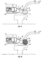
FIGS. 1A-1D illustrate a remotely operated vehicle (ROV) installing a mold around a subsea connector and pumping insulation into the mold, where a subsea gel injection system is integrated within the frame of the ROV, in accordance with certain aspects of the present invention. -
FIGS. 2A-2E illustrate a remotely operated vehicle (ROV) installing a mold around a subsea connector and pumping insulation into the mold, where a subsea gel injection system is deployed separately from the ROV, in accordance with certain aspects of the present invention. -
FIG. 3 illustrates a cross sectional view of a subsea gel insulation mold, in accordance with certain aspects of the present invention. -
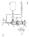
FIG. 4 illustrates a diagram of a subsea gel injection system, in accordance with certain aspects of the present invention. -
FIGS. 1A-1D illustrate one embodiment of the present invention, in which a remotely operated vehicle (ROV) installs insulation around an item to be insulated by the use of a mold. The ROV, such as, for example, the INNOVATOR® manufactured by Saipem America Inc. of Houston, Texas, is launched and lowered to the work site near the item to be insulated. In one embodiment, a subsea gel injection system is a remotely operated package integrated within the frame of the ROV. Referring toFIG. 1A ,ROV 2 integrated with subseagel injection system 50 approachessubsea connector 14 while holding subseagel insulation mold 30 withROV manipulator 4. -
Subsea connector 14 connects subsea wellhead, manifold or othersimilar equipment 10 toflowline 18. Flowline 18 is commonly covered withinsulation 20 to reduce heat loss fromflowline 18. Althoughsubsea connector 14 is insulated in one embodiment of the present invention, any subsea equipment that can be surrounded by a mold can be insulated by certain embodiments of the present invention. - Mold 30 may be a pre-engineered fiberglass, plastic or metal enclosure, the purpose of which is to fit around
subsea connector 14 or other subsea equipment to be insulated. Generally,mold 30 will comprise an enclosure withhinges 34 that is closed and secured around the item to be insulated with latches 37 (seeFIG. 3 ). In one illustrative embodiment,mold 30 further comprisesgaskets 36 to provide a tight seal between the mold and the item to be insulated. Mold 30 includesreceptacle 31 into which the insulation material is injected. The insulation material is injected as a liquid solution that is a combination of an insulation solution and a catalyst solution mixed together during the injection process. The liquid solution is then allowed to solidify, forming a gel molded insulation. - The insulation solution and catalyst is well known in the art. One type of insulation solution that is mixed with a catalyst upon or preceding injection into the mold is DEEPGEL(TM), offered by Ythan Environmental Services Ltd. However, any type of insulation solution that can be injected into a mold and allowed to cure or harden can be used, and such insulation solutions may not even require the use of a catalyst for hardening the insulation. Thus, in some instances, insulation (whether cured or not cured) may refer to the insulation solution or the combination insulation solution and catalyst mixture. One of ordinary skill in the art will appreciate that the volume of insulation solution and catalyst pumped into the mold will vary based upon the amount of insulation desired for the particular item to be insulated, the enclosed volume of the mold, type of insulation solution and catalyst utilized, and subsea conditions (such as temperature, pressure, and time required to fill the mold) surrounding the item to be insulated.
- In a preferred embodiment,
mold 30 is installed subsea by a ROV, but in other embodiments the mold is preinstalled on the item to be insulated before being lowered subsea. In one embodiment,manipulator 4 connects a hydraulic hot stab tomold installation tool 32 that is used in conjunction withmold 30. The hydraulic hot stab powersmold installation tool 32 to pick up and/or grabmold 30 by the use of hydraulic clamps, lock and/or enclosemold 30 aroundsubsea connector 14, set, close and/or locklatches 37 onmold 30, and release and/or disconnectmold installation tool 32 frommold 30. In an alternative embodiment,mold installation tool 32 may not be necessary andmanipulator 4 directly grabsmold 30 and enclosesmold 30 around the item to be insulated. In one embodiment, multiple molds are attached to the ROV itself, but if numerous molds are needed, a separate mold deployment skid can be provided to supply the additional molds. - Referring to
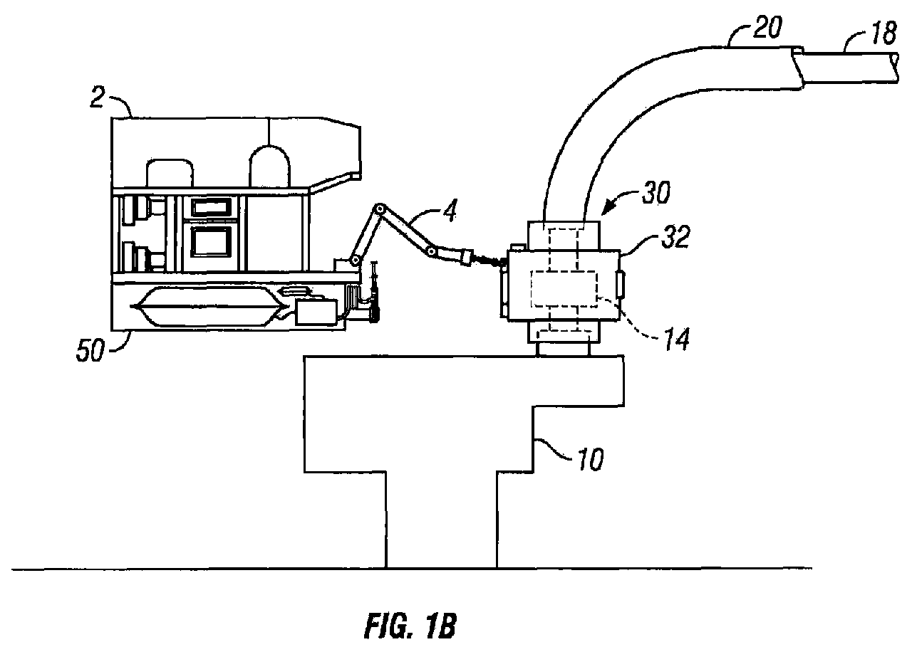
FIG. 1B ,ROV 2 installs subseagel insulation mold 30 onsubsea connector 14 by the use ofmanipulator 4. In one embodiment,manipulator 4 surroundssubsea connector 14 withmold 30 and usesmold installation tool 32 to lockmold 30 aroundsubsea connector 14.Mold installation tool 32 remains onmold 30 while the insulation solution/catalyst mixture is injected into the mold from subseagel injection system 50, or alternatively,manipulator 4 then releasesmold installation tool 32 frommold 30 whilemold 30 remains aroundsubsea connector 14. - Referring to
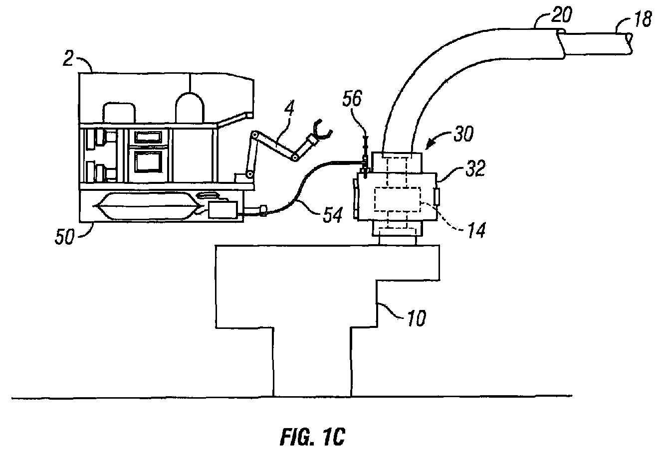
FIG. 1C ,manipulator 4 grabshot stab 56 and connectshot stab 56 tomold 30 by placinghot stab 56 into a receptacle onmold 30.Hot stab 56 is connected toinjection hose 54, which is connected to subseagel injection system 50. - Referring to
FIG. 1D , subseagel injection system 50 pumps a desired volume of an insulation solution and catalyst mixture into subseagel insulation mold 30, forminginsulation 38 betweensubsea connector 14 andmold 30. Aftermold 30 is filled with the desired amount of the insulation/catalyst mixture, subseagel injection system 50 stops pumping andROV 2 disconnectshot stab 56 frommold 30. The flow of catalyst is then stopped, and a small quantity of insulation solution is pumped throughinjection hose 54 andhot stab 56 to clean out the mixed solution, preventing the insulation/catalyst mixture from curing and hardening withinhot stab 56 and other components.ROV 2 is now ready to install the next mold, or if all molds are installed, the ROV is recovered to the surface. - Another illustrative embodiment of the present invention is illustrated in
FIGS. 2A-2E , which employs separate skids and may be useful when there are a number of molds to be filled with insulation. Referring toFIG. 2A , subsea insulationsolution reservoir skid 46 and subseamold deployment skid 44 are lowered by wire from the water surface to an area in the vicinity of the work site.ROV 2 may or may not be lowered or positioned at the same time that insulationsolution reservoir skid 46 and subseamold deployment skid 44 are lowered. Rather than being integrated within the frame ofROV 2, subseagel injection system 50,injection hose 54, andhot stab 56 are attached to subsea insulationsolution reservoir skid 46. - Referring to
FIG. 2B ,ROV 2 flies to molddeployment skid 44 and usesmanipulator 4 to grabmold installation tool 32.Manipulator 4 then usesmold installation tool 32 to pick upmold 30. Referring toFIG. 2C ,ROV 2 then fliesmold 30 over tosubsea connector 14, wheremanipulator 4 usesmold installation tool 32 to lockmold 30 aroundsubsea connector 14.Manipulator 4 then removesmold installation tool 32 and returns it to molddeployment skid 44, or in an alternative embodiment,mold installation tool 32 remains onmold 30 while the insulation solution/catalyst mixture is injected into the mold from subseagel injection system 50. - Referring to
FIG. 2D ,ROV 2 then flies over to insulationsolution reservoir skid 46 and usesmanipulator 4 to grabhot stab 56, after whichROV 2 flies over tomold 30 and placeshot stab 56 into a receptacle onmold 30 for the injection of an insulation solution and catalyst mixture into the mold.Hot stab 56 is connected toinjection hose 54, which is connected to subseagel injection system 50. - Referring to
FIG. 2E ,ROV 2 flies to insulationsolution reservoir skid 46 and usesmanipulator 4 to connect powerhot stab 58 to insulationsolution reservoir skid 46 to power subseagel injection system 50 from the power system ofROV 2, which is connected to powerhot stab 58 bypower line 59. Subseagel injection system 50 pumps a desired volume of an insulation solution and catalyst mixture into subseagel insulation mold 30, forminginsulation 38 betweensubsea connector 14 andmold 30. Aftermold 30 is filled with the desired amount of the insulation/catalyst mixture ROV 2 disconnectshot stab 56 frommold 30. The subseagel injection system 50 stops pumping the catalyst, and a small quantity of insulation solution is pumped throughhot stab 56 to clean out the mixed solution, preventing the insulation/catalyst mixture from curing and hardening withinhot stab 56 and other components.ROV 2 is now ready to install the next mold, or if all molds are installed, the ROV, mold deployment skid, and insulation solution reservoir skid are recovered to the surface. -
FIG. 4 illustrates an illustrative embodiment of subseagel injection system 50. As described herein, a subsea gel injection system in some situations may be attached to the ROV's frame, and in other situations may be lowered to the surface floor by line wire separately from the ROV. In both instances, the functionality of the subsea gel injection system remains substantially the same. When the subsea gel injection system is attached to the ROV, the injection hose and hot stab are preferably placed near the ROV's manipulator. If deployed separated from the ROV, the subsea gel injection system is not limited to the ROV's dimensions and thus it may be much larger than the ROV, which allows for greater pumping capabilities and larger catalyst and insulation solution reservoirs. Whether connected to the ROV or deployed separately, a pump module of the subsea gel injection system is connected to the ROV so as to draw power from the ROV system. For instance, if the pump module requires hydraulic power, then it is connected to the hydraulic system of the ROV, however, if the pump module is electric, then it would be connected to the electrical system of the ROV. - Referring to
FIG. 4 , subseagel injection system 50 comprisespump module 64, mixingtube 82,insulation solution reservoir 60, andcatalyst reservoir 62.Pump module 64 is used to pump the insulation/catalyst mixture through mixingtube 82,injection hose 54, andhot stab 56 and intomold 30. Mixingtube 82 is well known in the art and is preferably a tube with alternating spiraled vanes that mixes catalyst and insulation solution fluids as the insulation/catalyst mixture passes through mixingtube 82 and intoinjection hose 54.Injection hose 54 delivers the insulation/catalyst mixture from mixingtube 82 tohot stab 56 for the injection of the insulation/catalyst mixture intomold 30. - In one
embodiment pump module 64 comprisescatalyst cylinder pump 66,insulation cylinder pump 68,catalyst stop valve 70,suction hose 72,insulation check valves 74,hydraulic drive cylinder 76, anddirectional control valve 78. In operation, hydraulic pressure is inputted to the pump module and the direction of piston movement is selected bycontrol valve 78. One of ordinary skill will recognize thatpump module 64 is a typical reciprocating piston pump with integrated insulation and catalyst pumps that measure and dispense the insulation and catalyst. Thecatalyst cylinder pump 66,insulation cylinder pump 68, andhydraulic drive cylinder 76 are fixed to a common shaft so that the correct proportion of catalyst to insulation is always maintained. The pump may be manually or automatically reciprocated bycontrol valve 78. One of ordinary skill will appreciate that any pumping arrangement or design may be compatible with this invention as long as it is able to pump the desired ratio and amount of insulation solution and catalyst into the mold. -
Insulation solution reservoir 60 stores the fluid insulation solution, and in one embodiment, the insulation solution is pumped into the flexible bladder ofinsulation solution reservoir 60 on the surface. Similarly,catalyst reservoir 62 stores the fluid catalyst, and in one embodiment, the catalyst is pumped into the flexible bladder ofcatalyst reservoir 62 on the surface. - While the methods and systems of the present invention have been described in terms of preferred illustrative embodiments, it will be apparent to those of skill in the art that variations may be applied to what has been described herein without departing from the concept and scope of the invention. All such similar substitutes and modifications apparent to those skilled in the art are deemed to be within the scope and concept of the invention as it is set out in the following claims.
Claims (26)
- A system for installing subsea insulation comprising:a remotely operated vehicle;a subsea gel insulation mold installed subsea on an item to be insulated by the remotely operated vehicle; anda subsea gel injection system capable of pumping insulation into the installed subsea gel insulation mold.
- The system of claim 1, wherein the subsea gel injection system is integrated within the frame of the remotely operated vehicle.
- The system of claim 1, further comprising a subsea insulation solution reservoir skid.
- The system of claim 3, wherein the subsea gel injection system is attached to the subsea insulation solution reservoir skid.
- The system of claim 1, further comprising a subsea mold deployment skid.
- The system of claim 1, wherein the subsea gel insulation mold is selected from the group consisting of a pre-engineered fiberglass enclosure, a plastic enclosure, and a metal enclosure.
- The system of claim 1, further comprising a mold installation tool.
- The system of claim 1, wherein the subsea gel insulation mold is a hinged enclosure.
- The system of claim 1, wherein the subsea gel insulation mold comprises a receptacle for the injection of insulation.
- The system of claim 1, wherein the subsea gel injection system comprises an insulation solution reservoir.
- The system of claim 1, wherein the subsea gel injection system is capable of pumping catalyst into the subsea gel insulation mold.
- A method for installing subsea insulation comprising:using a remotely operated vehicle to install subsea a subsea gel insulation mold on an item to be insulated; andpumping insulation solution into the installed subsea gel insulation mold.
- The method of claim 12, wherein the insulation solution is pumped into the subsea gel insulation mold by the remotely operated vehicle.
- The method of claim 12, wherein the insulation solution is pumped into the subsea gel insulation mold by a subsea gel injection system.
- The method of claim 14, wherein the subsea gel injection system is attached to a subsea insulation solution reservoir skid.
- The method of claim 14, wherein the subsea gel injection system is integrated within the frame of the remotely operated vehicle.
- The method of claim 12, further comprising pumping catalyst into the subsea gel insulation mold.
- The method of claim 17, wherein the insulation solution and catalyst are pumped into the subsea gel insulation mold by a subsea gel injection system.
- The method of claim 12, wherein the remotely operated vehicle uses a mold installation tool to install the subsea gel insulation mold.
- The method of claim 12, wherein the subsea gel insulation mold is selected from the group consisting of a pre-engineered fiberglass enclosure, a plastic enclosure, and a metal enclosure.
- The method of claim 12, wherein the subsea gel insulation mold is a hinged enclosure.
- The method of claim 12, wherein the subsea gel insulation mold comprises a receptacle for the injection of insulation solution.
- A method for installing subsea insulation on subsea equipment comprising:a) providing subsea a plurality of subsea gel insulation molds;b) using a remotely operated vehicle subsea to grab one of the plurality of subsea gel insulation molds;c) using the remotely operated vehicle subsea to install one of the plurality of subsea gel insulation molds on an item to be insulated;d) pumping insulation solution subsea into one of the plurality of subsea gel insulation molds by a subsea gel injection system; ande) repeating steps b-d until the plurality of subsea gel insulation molds are insulated.
- The method of claim 23 wherein the plurality of subsea gel insulation molds are provided by a mold deployment skid.
- The method of claim 23, wherein the subsea gel injection system is attached to a subsea insulation solution reservoir skid.
- The method of claim 23, wherein the subsea gel injection system is attached to the subsea insulation solution reservoir skid.
Applications Claiming Priority (1)
| Application Number | Priority Date | Filing Date | Title |
|---|---|---|---|
| US12/235,235 US8006763B2 (en) | 2004-08-20 | 2008-09-22 | Method and system for installing subsea insulation |
Publications (2)
| Publication Number | Publication Date |
|---|---|
| EP2166264A2 true EP2166264A2 (en) | 2010-03-24 |
| EP2166264A3 EP2166264A3 (en) | 2016-08-17 |
Family
ID=41479068
Family Applications (1)
| Application Number | Title | Priority Date | Filing Date |
|---|---|---|---|
| EP09171026.9A Withdrawn EP2166264A3 (en) | 2008-09-22 | 2009-09-22 | Method and system for installing subsea insulation |
Country Status (2)
| Country | Link |
|---|---|
| US (1) | US8006763B2 (en) |
| EP (1) | EP2166264A3 (en) |
Cited By (1)
| Publication number | Priority date | Publication date | Assignee | Title |
|---|---|---|---|---|
| WO2018018668A1 (en) * | 2016-07-23 | 2018-02-01 | 杨越 | Hot-tapping fluid blasting device for unmanned ship |
Families Citing this family (19)
| Publication number | Priority date | Publication date | Assignee | Title |
|---|---|---|---|---|
| US8619134B2 (en) * | 2009-03-11 | 2013-12-31 | Seatrepid International, Llc | Unmanned apparatus traversal and inspection system |
| US20100310211A1 (en) * | 2009-04-16 | 2010-12-09 | Babin Robin Mark | Systems and methods for installation of devices around an element |
| SG175720A1 (en) * | 2009-06-25 | 2011-12-29 | Cameron Int Corp | Sampling skid for subsea wells |
| US20110304138A1 (en) * | 2010-06-09 | 2011-12-15 | Commoner Frederic G | Extended flange plumbing for deep-sea oil containment |
| US8424608B1 (en) * | 2010-08-05 | 2013-04-23 | Trendsetter Engineering, Inc. | System and method for remediating hydrates |
| US8434558B2 (en) * | 2010-11-15 | 2013-05-07 | Baker Hughes Incorporated | System and method for containing borehole fluid |
| US8540031B2 (en) * | 2010-12-29 | 2013-09-24 | Michael Rimi | Encapsulating device |
| US8919450B1 (en) * | 2012-08-08 | 2014-12-30 | Pinnacle Engineering Inc. | Collet connection insulation apparatus |
| GB2507572A (en) * | 2012-11-05 | 2014-05-07 | Lee Cothill Arran | Pipe joint insulation |
| NO335610B1 (en) * | 2013-03-27 | 2015-01-12 | Vetco Gray Scandinavia As | Device for thermal insulation of one or more elements in a subsea installation from surrounding cold sea water |
| BR102014016364A2 (en) | 2014-07-01 | 2016-02-10 | Fmc Technologies Do Brasil Ltda | shared acting system |
| US9581356B2 (en) * | 2015-03-06 | 2017-02-28 | Oceaneering International, Inc. | Subsea ROV-mounted hot water injection skid |
| BR112017027911B1 (en) | 2015-07-01 | 2022-06-07 | Fmc Technologies Do Brasil Ltda | System for receiving fluid flow from a plurality of external flow lines |
| US9938799B2 (en) * | 2015-09-03 | 2018-04-10 | Fmc Technologies, Inc. | High temperature insulation system and method |
| NO342327B1 (en) * | 2016-01-28 | 2018-05-07 | Vetco Gray Scandinavia As | Subsea arrangement |
| US10619781B2 (en) * | 2017-06-16 | 2020-04-14 | Benton Frederick Baugh | Method of subsea pipeline blockage remediation |
| NO345254B1 (en) * | 2018-11-21 | 2020-11-23 | Vetco Gray Scandinavia As | Locking Mechanism Tool and System |
| US20210231249A1 (en) | 2020-01-28 | 2021-07-29 | Chevron U.S.A. Inc. | Systems and methods for thermal management of subsea conduits using an interconnecting conduit and valving arrangement |
| US11634970B2 (en) * | 2020-01-28 | 2023-04-25 | Chevron U.S.A. Inc. | Systems and methods for thermal management of subsea conduits using a jumper having adjustable insulating elements |
Family Cites Families (36)
| Publication number | Priority date | Publication date | Assignee | Title |
|---|---|---|---|---|
| US1108840A (en) * | 1912-10-19 | 1914-08-25 | Matthew P Van Ness | Removable valve-insulation case. |
| US3650299A (en) * | 1970-12-14 | 1972-03-21 | Edwin Nail Seiler | Insulation apparatus and techniques for fluid-transmitting pipes |
| US3935632A (en) * | 1973-07-02 | 1976-02-03 | Continental Oil Company | Method of preparing an insulated negative buoyancy flow line |
| US3996654A (en) * | 1974-10-21 | 1976-12-14 | Albany International Corporation | Method of making syntatic modules |
| GB1579125A (en) * | 1976-06-14 | 1980-11-12 | Sigmund F | Heat-insulated pipe-lines |
| US4259981A (en) * | 1979-09-24 | 1981-04-07 | Busse Richard O | Removable insulated valve cover |
| US4527543A (en) * | 1979-12-10 | 1985-07-09 | State Industries, Inc. | Water heater construction |
| DE3216463A1 (en) * | 1982-05-03 | 1983-11-03 | Felten & Guilleaume Energietechnik GmbH, 5000 Köln | Process for producing a flexible district heating pipe |
| NO844213L (en) * | 1984-10-22 | 1986-04-23 | Viking Mjondalen As | PROCEDURE FOR SHOOTING CORROSION PROTECTED PIPELINE AND PIPE LENGTH TO USE IN EXECUTION OF THE PROCEDURE. |
| US4925605A (en) * | 1986-10-02 | 1990-05-15 | Field Foam Incorporated | Method of forming a heat foam insulation jacket |
| US4696324A (en) * | 1986-10-02 | 1987-09-29 | Petronko Dennis A | Heat foam insulation jacket |
| US4826215A (en) * | 1986-12-01 | 1989-05-02 | Sullivan Samuel R | Clamp |
| US4807669A (en) * | 1987-02-12 | 1989-02-28 | Prestidge Sr Gary R | Removable flexible pipe insulation |
| NL8800894A (en) * | 1988-04-07 | 1989-11-01 | Smit Offshore Contractors | METHOD FOR THERMALLY INSULATING COMPOSITE PIPELINES UNDER WATER AND SO INSULATED PIPELINE. |
| US4972759A (en) * | 1989-02-13 | 1990-11-27 | Nelson Thomas E | Thermal insulation jacket |
| US6264401B1 (en) * | 1995-12-29 | 2001-07-24 | Shell Oil Company | Method for enhancing the flow of heavy crudes through subsea pipelines |
| US6179523B1 (en) * | 1995-12-29 | 2001-01-30 | Shell Oil Company | Method for pipeline installation |
| US5732742A (en) * | 1996-07-01 | 1998-03-31 | Trigen Energy Corporation | Method for re-insulating intalled steam pipe insitu |
| US6200068B1 (en) * | 1998-02-06 | 2001-03-13 | Sonsub, Inc. | Hot tap fluid blaster apparatus and method of using same |
| US6000438A (en) * | 1998-02-13 | 1999-12-14 | Mcdermott Technology, Inc. | Phase change insulation for subsea flowlines |
| US6199595B1 (en) * | 1998-06-04 | 2001-03-13 | Jerry G. Baker | Insulated marine pipe apparatus and method of installation |
| US20010043991A1 (en) * | 1998-12-16 | 2001-11-22 | Lou W. Watkins | Method and apparatus for applying syntactic foam thermal insulation to a length of pipe |
| US6278096B1 (en) * | 1999-08-03 | 2001-08-21 | Shell Oil Company | Fabrication and repair of electrically insulated flowliness by induction heating |
| US6371693B1 (en) * | 1999-08-27 | 2002-04-16 | Shell Oil Company | Making subsea pipelines ready for electrical heating |
| US6939082B1 (en) * | 1999-09-20 | 2005-09-06 | Benton F. Baugh | Subea pipeline blockage remediation method |
| US6881266B1 (en) * | 1999-10-30 | 2005-04-19 | Pipeline Induction Heat Ltd. | Apparatus and method for coating pipes |
| NO313676B1 (en) * | 2000-02-18 | 2002-11-11 | Abb Offshore Systems As | Thermal protection of underwater installations |
| US6520261B1 (en) * | 2000-04-14 | 2003-02-18 | Fmc Technologies, Inc. | Thermal insulation material for subsea equipment |
| US6415868B1 (en) * | 2000-08-23 | 2002-07-09 | Fmc Corporation | Method and apparatus for preventing the formation of alkane hydrates in subsea equipment |
| FR2840314B1 (en) * | 2002-06-03 | 2004-08-20 | Inst Francais Du Petrole | THERMAL INSULATION METHOD, PROCESS FOR PREPARING AN INSULATING GEL AND INSULATING GEL OBTAINED |
| US20040081766A1 (en) * | 2002-10-28 | 2004-04-29 | Ahmad Zolghadri | Under water coating method |
| US7036596B2 (en) * | 2003-09-23 | 2006-05-02 | Sonsub Inc. | Hydraulic friction fluid heater and method of using same |
| US20060037756A1 (en) * | 2004-08-20 | 2006-02-23 | Sonsub Inc. | Method and apparatus for installing subsea insulation |
| US7661479B2 (en) * | 2005-05-25 | 2010-02-16 | Duron Systems, Inc. | Subsea insulating shroud |
| US20060272727A1 (en) * | 2005-06-06 | 2006-12-07 | Dinon John L | Insulated pipe and method for preparing same |
| US7784547B2 (en) * | 2006-05-01 | 2010-08-31 | Deep Sea Technologies, Inc. | Subsea connector insulation device |
-
2008
- 2008-09-22 US US12/235,235 patent/US8006763B2/en not_active Expired - Fee Related
-
2009
- 2009-09-22 EP EP09171026.9A patent/EP2166264A3/en not_active Withdrawn
Non-Patent Citations (1)
| Title |
|---|
| None * |
Cited By (1)
| Publication number | Priority date | Publication date | Assignee | Title |
|---|---|---|---|---|
| WO2018018668A1 (en) * | 2016-07-23 | 2018-02-01 | 杨越 | Hot-tapping fluid blasting device for unmanned ship |
Also Published As
| Publication number | Publication date |
|---|---|
| EP2166264A3 (en) | 2016-08-17 |
| US20090050328A1 (en) | 2009-02-26 |
| US8006763B2 (en) | 2011-08-30 |
Similar Documents
| Publication | Publication Date | Title |
|---|---|---|
| US8006763B2 (en) | Method and system for installing subsea insulation | |
| CN1831341B (en) | Subsea pumping system for hydrocarbon compound fluid, method and subsea pump | |
| US8789609B2 (en) | Submersible hydraulic artificial lift systems and methods of operating same | |
| CA2876901C (en) | Motor shroud for an electric submersible pump | |
| US9151131B2 (en) | Power and control pod for a subsea artificial lift system | |
| US20210040821A1 (en) | An in-situ system for mixing two or more chemical components downhole in a wellbore and a method employing same | |
| US8240952B2 (en) | Universal pump platform | |
| US8322427B2 (en) | Control system | |
| EP2087201B1 (en) | Sub sea processing system | |
| US20110155390A1 (en) | Apparatus and method for pumping a fluid and an additive from a downhole location into a formation or to another location | |
| US3525401A (en) | Pumpable plastic pistons and their use | |
| RU2569139C2 (en) | Electric pump system and method of transfer of fluid medium from underground well using this system | |
| RU2390660C2 (en) | Pump system for tandem motor | |
| US20100085064A1 (en) | Universal power and testing platform | |
| US20200102813A1 (en) | Rapid deployment subsea chemical injection system | |
| US8257103B2 (en) | Submersible pothead system for use in a well application | |
| NO342814B1 (en) | Wellbore and reservoir processing device | |
| RU99820U1 (en) | GARIPOV'S Borehole Pumping Packer Installation | |
| CN103597167A (en) | Method and device for supply of liquids for kill and scale to a subsea well | |
| RU2414584C1 (en) | Procedure for preparing well pump equipment by garipov to operation | |
| EP1628068B1 (en) | Method and apparatus for installing subsea insulation | |
| WO2019222241A1 (en) | Subsea flowline blockage remediation using internal heating device | |
| GB2439422A (en) | A submersible electric motor in a submersible pump system with facilitates connecting auxiliary tools | |
| AU2013207634B2 (en) | Power and control pod for a subsea artificial lift system | |
| GB2486256A (en) | Downhole sealing device |
Legal Events
| Date | Code | Title | Description |
|---|---|---|---|
| PUAI | Public reference made under article 153(3) epc to a published international application that has entered the european phase |
Free format text: ORIGINAL CODE: 0009012 |
|
| AK | Designated contracting states |
Kind code of ref document: A2 Designated state(s): AT BE BG CH CY CZ DE DK EE ES FI FR GB GR HR HU IE IS IT LI LT LU LV MC MK MT NL NO PL PT RO SE SI SK SM TR |
|
| PUAL | Search report despatched |
Free format text: ORIGINAL CODE: 0009013 |
|
| AK | Designated contracting states |
Kind code of ref document: A3 Designated state(s): AT BE BG CH CY CZ DE DK EE ES FI FR GB GR HR HU IE IS IT LI LT LU LV MC MK MT NL NO PL PT RO SE SI SK SM TR |
|
| RIC1 | Information provided on ipc code assigned before grant |
Ipc: F16L 59/14 20060101AFI20160712BHEP Ipc: F16L 1/26 20060101ALI20160712BHEP Ipc: B29C 45/00 20060101ALI20160712BHEP Ipc: F16L 59/16 20060101ALI20160712BHEP |
|
| 17P | Request for examination filed |
Effective date: 20170217 |
|
| RBV | Designated contracting states (corrected) |
Designated state(s): AT BE BG CH CY CZ DE DK EE ES FI FR GB GR HR HU IE IS IT LI LT LU LV MC MK MT NL NO PL PT RO SE SI SK SM TR |
|
| RIC1 | Information provided on ipc code assigned before grant |
Ipc: B29B 7/86 20060101ALN20171018BHEP Ipc: B29C 45/03 20060101ALI20171018BHEP Ipc: B29B 7/74 20060101ALN20171018BHEP Ipc: B29B 7/32 20060101ALN20171018BHEP Ipc: F16L 1/26 20060101ALI20171018BHEP Ipc: B29C 45/00 20060101ALN20171018BHEP Ipc: F16L 59/14 20060101AFI20171018BHEP Ipc: F16L 59/16 20060101ALI20171018BHEP |
|
| GRAP | Despatch of communication of intention to grant a patent |
Free format text: ORIGINAL CODE: EPIDOSNIGR1 |
|
| INTG | Intention to grant announced |
Effective date: 20171122 |
|
| STAA | Information on the status of an ep patent application or granted ep patent |
Free format text: STATUS: THE APPLICATION IS DEEMED TO BE WITHDRAWN |
|
| 18D | Application deemed to be withdrawn |
Effective date: 20180404 |