EP2165877A1 - Method of assembly of a supporting base for a child's car seat, base and child's car seat thus obtained - Google Patents
Method of assembly of a supporting base for a child's car seat, base and child's car seat thus obtained Download PDFInfo
- Publication number
- EP2165877A1 EP2165877A1 EP09169728A EP09169728A EP2165877A1 EP 2165877 A1 EP2165877 A1 EP 2165877A1 EP 09169728 A EP09169728 A EP 09169728A EP 09169728 A EP09169728 A EP 09169728A EP 2165877 A1 EP2165877 A1 EP 2165877A1
- Authority
- EP
- European Patent Office
- Prior art keywords
- base
- sections
- seat
- apt
- sitting
- Prior art date
- Legal status (The legal status is an assumption and is not a legal conclusion. Google has not performed a legal analysis and makes no representation as to the accuracy of the status listed.)
- Granted
Links
Images


Classifications
-
- B—PERFORMING OPERATIONS; TRANSPORTING
- B60—VEHICLES IN GENERAL
- B60N—SEATS SPECIALLY ADAPTED FOR VEHICLES; VEHICLE PASSENGER ACCOMMODATION NOT OTHERWISE PROVIDED FOR
- B60N2/00—Seats specially adapted for vehicles; Arrangement or mounting of seats in vehicles
- B60N2/24—Seats specially adapted for vehicles; Arrangement or mounting of seats in vehicles for particular purposes or particular vehicles
- B60N2/26—Seats specially adapted for vehicles; Arrangement or mounting of seats in vehicles for particular purposes or particular vehicles for children
- B60N2/28—Seats readily mountable on, and dismountable from, existing seats or other parts of the vehicle
- B60N2/2821—Seats readily mountable on, and dismountable from, existing seats or other parts of the vehicle having a seat and a base part
-
- B—PERFORMING OPERATIONS; TRANSPORTING
- B60—VEHICLES IN GENERAL
- B60N—SEATS SPECIALLY ADAPTED FOR VEHICLES; VEHICLE PASSENGER ACCOMMODATION NOT OTHERWISE PROVIDED FOR
- B60N2/00—Seats specially adapted for vehicles; Arrangement or mounting of seats in vehicles
- B60N2/24—Seats specially adapted for vehicles; Arrangement or mounting of seats in vehicles for particular purposes or particular vehicles
- B60N2/26—Seats specially adapted for vehicles; Arrangement or mounting of seats in vehicles for particular purposes or particular vehicles for children
- B60N2/28—Seats readily mountable on, and dismountable from, existing seats or other parts of the vehicle
- B60N2/2875—Seats readily mountable on, and dismountable from, existing seats or other parts of the vehicle inclinable, as a whole or partially
-
- B—PERFORMING OPERATIONS; TRANSPORTING
- B60—VEHICLES IN GENERAL
- B60N—SEATS SPECIALLY ADAPTED FOR VEHICLES; VEHICLE PASSENGER ACCOMMODATION NOT OTHERWISE PROVIDED FOR
- B60N2/00—Seats specially adapted for vehicles; Arrangement or mounting of seats in vehicles
- B60N2/68—Seat frames
- B60N2/682—Joining means
-
- B—PERFORMING OPERATIONS; TRANSPORTING
- B60—VEHICLES IN GENERAL
- B60N—SEATS SPECIALLY ADAPTED FOR VEHICLES; VEHICLE PASSENGER ACCOMMODATION NOT OTHERWISE PROVIDED FOR
- B60N2/00—Seats specially adapted for vehicles; Arrangement or mounting of seats in vehicles
- B60N2/68—Seat frames
- B60N2/686—Panel like structures
Definitions
- the object of the present invention is a method for implementing a supporting base of a car seat for children, according to the preamble of the corresponding independent claim.
- Car seats are known including a base suitable to rest and to be constrained to a car seat (by means of a usual belt associated to the latter) and apt to support an upper structure suitable to directly contain the child, the latter being equipped with usual belt members retaining the child.
- the structure is mobile with respect to the base and it allows to place the child in at least two positions, one thereof allows him/her to sleep.
- such base comprises a first portion or sitting portion, apt to be rested onto the car seat sitting, and a second portion or backrest portion, apt to be rested against the backrest of such seat.
- the known bases are currently obtained with constructive methodologies leading to a relatively high cost of the same, which reflects onto the whole cost of the entire seat.
- the object of the present invention is to offer a method for obtaining a base for a car child seat allowing to implement such base in a quick way, with a low number of pieces, which can be easily coupled therebetween, this leading to have a manufactured article with low costs with respect to the currently known bases for seats.
- a base of a car seat for children comprises a body 1 having a first portion or sitting portion 2, apt to be placed on the sitting of a seat of the above-mentioned vehicle, and a second portion or backrest portion 3, apt to rest against the backrest of such seat.
- Said body 1 further comprises opposite side flanks 5 having lightening recesses 6, an upper portion 7 from the flanks thereof 7A, 7B ends 8, 9 of a cross pin 10, sliding within tilted guides 12 implemented within such flanks 7A, 7B, protrude, said ends 8 and 9 being apt to be constrained to flanks 13 and 14 of a first body 15 of a structure 16, apt to be overlapped to the base, thereupon a second body 17 is mounted.
- Such upper structure 16 is apt to contain a child (and to retain him/her by means of usual, not shown retaining members) and it is mobile along the base with the motion of the pin 10 within the guides 12.
- the base body 1 comprises two sections 20 and 21 (on the inside hollow and stiffened by means of inner ribs), each one equipped with a portion of the sitting portion 2 and a portion of the backrest portion 3 of the base.
- Each section 20 and 21 further comprises one of the side flanks 5 of such base and one of the flanks 7A, 7B of the upper portion 7 of the latter.
- the first section 20 has a second flank 20A apt to couple with an angled second flank 21A of the other section 21.
- Such coupling is a shape coupling, in the sense that the flank 20A of the first section 20 couples, by following the shape, with the flank 21A of the second section 21.
- the latter comprises a peripheral recess 25 apt to receive a projection 26 of the flank 20A of the first section so as to facilitate and guide the coupling between the sections 20 and 21.
- the base of the car seat according to the invention is implemented by means of mechanical coupling of two sections 20, 21 having shapes so as to reproduce each one a portion of the base itself.
- Such sections are obtained by moulding of plastic material with moulds with limited sizes with respect to that of moulds which currently allow to implement the bases for car seats available on the market.
- flanks 20A, 21A of the sections apt to couple therebetween which result to be inside the portion of the backrest 3 with the assembled body 1, can have a lying position at least parallel to a mid-plane K of the seat base (and of the portions 2, 3 thereof), but they could have also a tilted lying position with respect to said plane K (obviously provided that such flanks allow a shape coupling therebetween).
- such sections 20, 21 are coupled at an area inside the portion 3 of the body 1.
- the sections 20 and 21 are coupled by bringing their flanks 20A and 21A in contact therebetween and by making the projection 26 and the members 27, 28, 29 to penetrate inside the recess 25 and the respective seats. Then, one proceeds with constraining the two sections therebetween by means of (not shown) screws inserted in seats 30 provided below said sections and on the sides thereof.
- a member 43 apt to receive a belt of the vehicle seat, is also associated to the sections 20, 21, such member 43 having wings 44 apt to penetrate inside the inner seats and a section (in the example, that 20) and a seat 45 for a screw 46 constraining (from outside) to the other section (in the example, that 21).
- the member 43 is positioned, once the seat is assembled, between the base and the upper structure (16).
- the upper structure 16 is mounted thereon with modes known on themselves.
Landscapes
- Engineering & Computer Science (AREA)
- Aviation & Aerospace Engineering (AREA)
- Transportation (AREA)
- Mechanical Engineering (AREA)
- Health & Medical Sciences (AREA)
- Child & Adolescent Psychology (AREA)
- General Health & Medical Sciences (AREA)
- Seats For Vehicles (AREA)
- Automobile Manufacture Line, Endless Track Vehicle, Trailer (AREA)
Abstract
Description
- The object of the present invention is a method for implementing a supporting base of a car seat for children, according to the preamble of the corresponding independent claim.
- The so-obtained base and the seat equipped with such base are also claimed, according to the corresponding claims.
- Car seats are known including a base suitable to rest and to be constrained to a car seat (by means of a usual belt associated to the latter) and apt to support an upper structure suitable to directly contain the child, the latter being equipped with usual belt members retaining the child. Usually, the structure is mobile with respect to the base and it allows to place the child in at least two positions, one thereof allows him/her to sleep.
- Usually, such base comprises a first portion or sitting portion, apt to be rested onto the car seat sitting, and a second portion or backrest portion, apt to be rested against the backrest of such seat.
- The known bases are currently obtained with constructive methodologies leading to a relatively high cost of the same, which reflects onto the whole cost of the entire seat.
- The object of the present invention is to offer a method for obtaining a base for a car child seat allowing to implement such base in a quick way, with a low number of pieces, which can be easily coupled therebetween, this leading to have a manufactured article with low costs with respect to the currently known bases for seats.
- These and other objects which will be evident to the person skilled in the art are achieved by a method for obtaining a base for car child seat according to the enclosed corresponding claim. These objects are also achieved by a base obtained with such method and a car seat for children according to the corresponding claims.
- For a better understanding of the present invention the following drawings are enclosed by way of simple example, but not for limitative purposes, wherein:
-
figure 1 shows a perspective view from the back of a base for car seat for children during a phase of its assembly; -
figure 2 shows a perspective view from the bottom of the base offigure 1 in the assembly phase shown in the latter; -
figure 3 shows a view from the back of the base of the above figures during the assembly phase shown in the latter; -
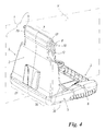
figure 4 shows a perspective view from the back of the assembled base offigure 1 ; -
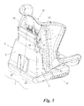
figure 5 shows a perspective view from the back of a first assembly phase of a car seat for children having a base obtained according to the invention; -
figure 6 shows a perspective view analogous to that offigure 5 , but of another additional assembly phase of the car seat for children shown in such figure. - By referring to the mentioned figures, a base of a car seat for children comprises a
body 1 having a first portion or sittingportion 2, apt to be placed on the sitting of a seat of the above-mentioned vehicle, and a second portion orbackrest portion 3, apt to rest against the backrest of such seat. Saidbody 1 further comprisesopposite side flanks 5 having lighteningrecesses 6, anupper portion 7 from the flanks thereof 7A,7B ends cross pin 10, sliding withintilted guides 12 implemented withinsuch flanks ends flanks first body 15 of astructure 16, apt to be overlapped to the base, thereupon asecond body 17 is mounted. Suchupper structure 16 is apt to contain a child (and to retain him/her by means of usual, not shown retaining members) and it is mobile along the base with the motion of thepin 10 within theguides 12. - According to the invention, the
base body 1 comprises twosections 20 and 21 (on the inside hollow and stiffened by means of inner ribs), each one equipped with a portion of the sittingportion 2 and a portion of thebackrest portion 3 of the base. Eachsection side flanks 5 of such base and one of theflanks upper portion 7 of the latter. - Moreover, the
first section 20 has asecond flank 20A apt to couple with an angledsecond flank 21A of theother section 21. Such coupling is a shape coupling, in the sense that theflank 20A of thefirst section 20 couples, by following the shape, with theflank 21A of thesecond section 21. Preferably, the latter comprises aperipheral recess 25 apt to receive aprojection 26 of theflank 20A of the first section so as to facilitate and guide the coupling between thesections - Furthermore, at least from the
flank 20A of the firstsection coupling members flank 21A of the second section so as to guide the coupling between the latter. Such coupling members are implemented as a single piece with the corresponding section and advantageously have particular shapes (for example with rectangular, polygonal or circular section) apt to simplify and guarantee the correct and single coupling with the respective seats. Thanks to such solution, the base of the car seat according to the invention is implemented by means of mechanical coupling of twosections - The
flanks backrest 3 with the assembledbody 1, can have a lying position at least parallel to a mid-plane K of the seat base (and of theportions such sections portion 3 of thebody 1. - After having obtained them, the
sections flanks projection 26 and themembers recess 25 and the respective seats. Then, one proceeds with constraining the two sections therebetween by means of (not shown) screws inserted inseats 30 provided below said sections and on the sides thereof. - During the assembly, a
member 43, apt to receive a belt of the vehicle seat, is also associated to thesections such member 43 havingwings 44 apt to penetrate inside the inner seats and a section (in the example, that 20) and aseat 45 for ascrew 46 constraining (from outside) to the other section (in the example, that 21). Themember 43 is positioned, once the seat is assembled, between the base and the upper structure (16). - Once the base is assembled, the
upper structure 16 is mounted thereon with modes known on themselves. - Thanks to the invention it is possible obtaining, with low costs and simpler modes than the ones currently used for implementing analogous products, a seat base apt to support an upper structure for containing a child. As a consequence, also a lower cost of the so-implemented seat is obtained.
- An embodiment of the invention has been described. However, still other embodiments are possible in the light of such description and they are considered to fall within the scope of the following claims.
Claims (12)
- A method for implementing a supporting base of a car seat, the latter including said base suitable to rest onto a seat of such vehicle and apt to support an upper structure (16) suitable to receive and retain a child, the base comprising a body (1) having a first (2) and a second (3) portion, the first sitting portion (2) being apt to rest onto the seat sitting and the second backrest portion (3) being apt to rest onto the backrest of such seat, characterized in that it is provided to obtain such base in at least two sections (20, 21), each section (20, 21) comprising a portion of the base portion and a portion of the sitting portion of the base, said sections being then coupled therebetween and joined so as to implement the above-mentioned base, said sections being coupled at an area inside the backrest portion (3) of the base body (1).
- The method according to claim 1, characterized in that each section (20, 21) is implemented by moulding, in plastic material.
- The method according to claim 1, characterized in that it is provided to associate to at least one (20) of the above-mentioned sections (20, 21) of the base body (1) coupling means (26, 27, 28, 29) apt to guide the coupling of the sections themselves, in the other (21) of such sections (20, 21) being obtained countermeans (26) for cooperating with said coupling means during the implementation of the above-mentioned body (1).
- The method according to claim 3, characterized in that the coupling means are members (26, 27, 28, 29) projecting from one (20) of such sections (20, 21), the countermeans being seats (26) for such means, the latter preferably having a shape so as to make univocal the coupling with the related seats.
- The method according to claim 1, characterized in that the coupling between the sections (20, 21) takes place along flanks (20A, 21A) having complementary shapes, in that after such coupling a junction by means of mechanical joints, such as screws or similar, of the coupled sections is provided.
- A base for car child seat, said base comprising a body (1) having a first sitting portion (2) suitable to rest on a sitting of a seat of such car and a second backrest portion (3) suitable to rest against a backrest of such seat, said base supporting an upper structure (16) apt to receive and retain a child, characterized in that said body (1) comprises at least two sections (20, 21) joined therebetween and each provided with a portion of the first sitting portion (2) and with a portion of the second backrest portion (3) of the above-mentioned body (1), said sections being coupled at a flank thereof (20A, 21A) which results to be inside the backrest portion (3) of such body.
- The base according to claim 6, characterized in that at least one of the sections (20, 21) of the base body (1) has projecting members (26, 27, 28, 29) apt to couple with corresponding seats (26) of the other section, said projecting members having preferably a shape apt to allow the shape coupling with the corresponding seats and to make univocal the constraint thereof.
- The base according to claim 6, characterized in that each section has a flank (5) of the base body (1) and one of the flanks (7A, 7B) of the upper portion (7) of the latter, from such flanks projecting ends (8, 9) of a pin (10) joining the upper structure (6) to the base, said pin being able to move in guides inclined within such flanks (7A, 7B).
- The base according to claim 6, characterized in that the coupled flanks (20A, 21A) of said sections (20, 21) lie on a mid-plane (K) of the base body (1).
- The base according to claim 6, characterized in that the coupled flanks (20A, 21A) of said sections (20, 21) lie on an inclined plane with respect to the mid-plane (K) of the base body (1).
- The base according to claim 6, characterized in that a member (43) is provided, apt to receive a belt of the vehicle seat and constrained to said section (20, 21), said member (43) being wholly integral to at least one of such sections (20, 21) and being suitable to be interposed between said base and the upper structure (16).
- Car seat for children comprising a base and an upper structure (16) associated to such base, the latter comprising a body (1) having a first sitting portion (2) and a second backrest portion (3) apt, respectively, to position at a sitting and a backrest of a seat of such car, characterized in that said base comprises at least two sections (20, 21) constrained therebetween and each one provided with a portion of the first sitting portion (2) and with a portion of the second backrest portion (3) of the above-mentioned body (1), said sections being coupled at a flank (20A, 21A) which results to be inside the backrest portion (3) mentioned above.
Applications Claiming Priority (1)
| Application Number | Priority Date | Filing Date | Title |
|---|---|---|---|
| ITMI2008A001654A IT1392052B1 (en) | 2008-09-17 | 2008-09-17 | METHOD TO REALIZE A BASIS OF SUPPORT FOR A CAR SEAT FOR CHILDREN, BASE AND SEAT SO OBTAINED |
Publications (2)
| Publication Number | Publication Date |
|---|---|
| EP2165877A1 true EP2165877A1 (en) | 2010-03-24 |
| EP2165877B1 EP2165877B1 (en) | 2011-01-19 |
Family
ID=40547529
Family Applications (1)
| Application Number | Title | Priority Date | Filing Date |
|---|---|---|---|
| EP09169728A Not-in-force EP2165877B1 (en) | 2008-09-17 | 2009-09-08 | Method of assembly of a supporting base for a child's car seat, base and child's car seat thus obtained |
Country Status (6)
| Country | Link |
|---|---|
| US (1) | US8047608B2 (en) |
| EP (1) | EP2165877B1 (en) |
| AT (1) | ATE495944T1 (en) |
| DE (1) | DE602009000628D1 (en) |
| ES (1) | ES2359613T3 (en) |
| IT (1) | IT1392052B1 (en) |
Families Citing this family (6)
| Publication number | Priority date | Publication date | Assignee | Title |
|---|---|---|---|---|
| US10220734B2 (en) | 2013-03-05 | 2019-03-05 | Pidyon Controls Inc. | Car seat |
| US8911015B2 (en) | 2013-03-05 | 2014-12-16 | Yochanan Cohen | Car seat |
| US9487110B2 (en) | 2014-03-05 | 2016-11-08 | Pidyon Controls Inc. | Car seat |
| US9616782B2 (en) | 2014-08-29 | 2017-04-11 | Pidyon Controls Inc. | Car seat vehicle connection system, apparatus, and method |
| EP3294590A4 (en) | 2015-05-12 | 2019-01-23 | Pidyon Controls Inc. | CAR SEAT AND CONNECTION SYSTEM |
| US10737593B1 (en) | 2018-07-02 | 2020-08-11 | Summer Infant (Usa), Inc. | Car seat |
Citations (3)
| Publication number | Priority date | Publication date | Assignee | Title |
|---|---|---|---|---|
| US20040239164A1 (en) * | 1998-10-30 | 2004-12-02 | Vits Charles G. | System of seats for a vehicle |
| EP1493614A2 (en) | 2003-06-30 | 2005-01-05 | Combi Corporation | Child seat |
| EP1728675A1 (en) * | 2005-06-03 | 2006-12-06 | Aprica Ikujikenkyukai Aprica Kassai Kabushikikaisha | Detachable child safety seat |
Family Cites Families (20)
| Publication number | Priority date | Publication date | Assignee | Title |
|---|---|---|---|---|
| US371091A (en) * | 1887-10-04 | Extensible seat | ||
| US1318569A (en) * | 1919-10-14 | Planodraph co | ||
| US843780A (en) * | 1906-01-24 | 1907-02-12 | Convertible Couch And Chair Company | Convertible couch. |
| US954594A (en) * | 1909-04-01 | 1910-04-12 | Alvoni G Shaw | Convertible chair. |
| US966891A (en) * | 1909-05-26 | 1910-08-09 | Mary R Moore | Extensible seat or the like. |
| US2699202A (en) * | 1954-01-15 | 1955-01-11 | James W Leary | Expansible chair |
| US2800947A (en) * | 1956-09-21 | 1957-07-30 | Robert G Thiem | Retractable-back vehicle safety seat |
| US3637253A (en) * | 1969-10-03 | 1972-01-25 | Warren E Maule | Laterally slidable seat |
| US3743351A (en) * | 1971-07-20 | 1973-07-03 | C Harris | Laterally expandable couch |
| US3759572A (en) * | 1972-06-20 | 1973-09-18 | Harter Corp | Segmented sling seat frame with stabilizing connection means having concealed adjustment for facilitating coverage thereof |
| CH657259A5 (en) * | 1982-11-15 | 1986-08-29 | Hansrudolf Zollinger | UPHOLSTERY FURNITURE. |
| US4493285A (en) * | 1983-02-16 | 1985-01-15 | Williams Donald F | Adjustable expandable slip-on canoe back rest |
| US4765678A (en) * | 1987-04-14 | 1988-08-23 | James Huang | Collapsible settee |
| US4824171A (en) * | 1988-03-17 | 1989-04-25 | Hollingsworth W Dale | Collapsible beach chair |
| US5516194A (en) * | 1991-06-14 | 1996-05-14 | Maule; Warren E. | Combination child's seat and armrest for a vehicle |
| US5564786A (en) * | 1994-11-10 | 1996-10-15 | Labac Systems, Inc. | Modular adjustable seat frame for wheelchairs |
| SE506462C2 (en) * | 1995-11-15 | 1997-12-15 | Handinter Ag | Wheelchair seat with adjustable width |
| US5660436A (en) * | 1995-11-17 | 1997-08-26 | Wilson; Michael | Laterally extendable furniture |
| US6913318B2 (en) * | 2002-12-03 | 2005-07-05 | Pride Mobility Products Corporation | Adjustable seat support for a wheelchair |
| US6824220B1 (en) * | 2003-12-19 | 2004-11-30 | Gregory P. Davison | Modular furniture retaining system |
-
2008
- 2008-09-17 IT ITMI2008A001654A patent/IT1392052B1/en active
-
2009
- 2009-09-08 AT AT09169728T patent/ATE495944T1/en not_active IP Right Cessation
- 2009-09-08 ES ES09169728T patent/ES2359613T3/en active Active
- 2009-09-08 DE DE602009000628T patent/DE602009000628D1/en active Active
- 2009-09-08 EP EP09169728A patent/EP2165877B1/en not_active Not-in-force
- 2009-09-15 US US12/559,686 patent/US8047608B2/en active Active
Patent Citations (3)
| Publication number | Priority date | Publication date | Assignee | Title |
|---|---|---|---|---|
| US20040239164A1 (en) * | 1998-10-30 | 2004-12-02 | Vits Charles G. | System of seats for a vehicle |
| EP1493614A2 (en) | 2003-06-30 | 2005-01-05 | Combi Corporation | Child seat |
| EP1728675A1 (en) * | 2005-06-03 | 2006-12-06 | Aprica Ikujikenkyukai Aprica Kassai Kabushikikaisha | Detachable child safety seat |
Also Published As
| Publication number | Publication date |
|---|---|
| ITMI20081654A1 (en) | 2010-03-17 |
| IT1392052B1 (en) | 2012-02-09 |
| US20100066141A1 (en) | 2010-03-18 |
| ES2359613T3 (en) | 2011-05-25 |
| EP2165877B1 (en) | 2011-01-19 |
| ATE495944T1 (en) | 2011-02-15 |
| DE602009000628D1 (en) | 2011-03-03 |
| US8047608B2 (en) | 2011-11-01 |
Similar Documents
| Publication | Publication Date | Title |
|---|---|---|
| EP2165877A1 (en) | Method of assembly of a supporting base for a child's car seat, base and child's car seat thus obtained | |
| US11259648B2 (en) | System, apparatus, and method for a convertible child high-chair and step stool | |
| US9039079B2 (en) | Children's tray with placement indicator | |
| US9603464B2 (en) | Booster seat with stowable tray and/or stowable securing strap | |
| JP2023503122A (en) | modular furniture system | |
| CN101391618A (en) | Stroller trays and methods of mounting the same on strollers | |
| CN102582480A (en) | child booster seat | |
| US20230146888A1 (en) | System, apparatus, and method for a convertible child high-chair and step stool | |
| US20170119172A1 (en) | Booster seat with stowable tray compartment and base panel | |
| JP2013516352A5 (en) | ||
| EP3165130A1 (en) | High chair for children convertible into a booster seat | |
| US20140054936A1 (en) | Juvenile seat assembly | |
| DE602004008530D1 (en) | A child seat with armrests for motor vehicles | |
| US7360830B2 (en) | Juvenile vehicle seat base with cup holder | |
| US20100038935A1 (en) | Multipurpose furniture assembly | |
| GB2492477A (en) | Baby mattress and crib | |
| EP3295832A1 (en) | Booster seat with stowable tray compartment and base panel | |
| US1478449A (en) | Rocking-horse | |
| KR101435077B1 (en) | Cup installing apparatus for folded cup carrier | |
| CN204561573U (en) | Booster chair with stowable tray and/or stowable securing strap | |
| USD914376S1 (en) | Child seat | |
| JP3025731U (en) | Car seat tray | |
| JP2007230676A (en) | Knockdown circulating transfer conveyor | |
| KR101657574B1 (en) | A baby car seat which is easy to control the angle and height | |
| CN223845327U (en) | Child dining chair convenient to store |
Legal Events
| Date | Code | Title | Description |
|---|---|---|---|
| PUAI | Public reference made under article 153(3) epc to a published international application that has entered the european phase |
Free format text: ORIGINAL CODE: 0009012 |
|
| AK | Designated contracting states |
Kind code of ref document: A1 Designated state(s): AT BE BG CH CY CZ DE DK EE ES FI FR GB GR HR HU IE IS IT LI LT LU LV MC MK MT NL NO PL PT RO SE SI SK SM TR |
|
| AX | Request for extension of the european patent |
Extension state: AL BA RS |
|
| 17P | Request for examination filed |
Effective date: 20100709 |
|
| GRAP | Despatch of communication of intention to grant a patent |
Free format text: ORIGINAL CODE: EPIDOSNIGR1 |
|
| GRAS | Grant fee paid |
Free format text: ORIGINAL CODE: EPIDOSNIGR3 |
|
| GRAA | (expected) grant |
Free format text: ORIGINAL CODE: 0009210 |
|
| AK | Designated contracting states |
Kind code of ref document: B1 Designated state(s): AT BE BG CH CY CZ DE DK EE ES FI FR GB GR HR HU IE IS IT LI LT LU LV MC MK MT NL NO PL PT RO SE SI SK SM TR |
|
| REG | Reference to a national code |
Ref country code: GB Ref legal event code: FG4D |
|
| REG | Reference to a national code |
Ref country code: CH Ref legal event code: EP |
|
| REG | Reference to a national code |
Ref country code: IE Ref legal event code: FG4D |
|
| REF | Corresponds to: |
Ref document number: 602009000628 Country of ref document: DE Date of ref document: 20110303 Kind code of ref document: P |
|
| REG | Reference to a national code |
Ref country code: DE Ref legal event code: R096 Ref document number: 602009000628 Country of ref document: DE Effective date: 20110303 |
|
| REG | Reference to a national code |
Ref country code: NL Ref legal event code: T3 |
|
| REG | Reference to a national code |
Ref country code: ES Ref legal event code: FG2A Ref document number: 2359613 Country of ref document: ES Kind code of ref document: T3 Effective date: 20110525 |
|
| LTIE | Lt: invalidation of european patent or patent extension |
Effective date: 20110119 |
|
| PG25 | Lapsed in a contracting state [announced via postgrant information from national office to epo] |
Ref country code: LT Free format text: LAPSE BECAUSE OF FAILURE TO SUBMIT A TRANSLATION OF THE DESCRIPTION OR TO PAY THE FEE WITHIN THE PRESCRIBED TIME-LIMIT Effective date: 20110119 Ref country code: NO Free format text: LAPSE BECAUSE OF FAILURE TO SUBMIT A TRANSLATION OF THE DESCRIPTION OR TO PAY THE FEE WITHIN THE PRESCRIBED TIME-LIMIT Effective date: 20110419 Ref country code: IS Free format text: LAPSE BECAUSE OF FAILURE TO SUBMIT A TRANSLATION OF THE DESCRIPTION OR TO PAY THE FEE WITHIN THE PRESCRIBED TIME-LIMIT Effective date: 20110519 Ref country code: SE Free format text: LAPSE BECAUSE OF FAILURE TO SUBMIT A TRANSLATION OF THE DESCRIPTION OR TO PAY THE FEE WITHIN THE PRESCRIBED TIME-LIMIT Effective date: 20110119 Ref country code: HR Free format text: LAPSE BECAUSE OF FAILURE TO SUBMIT A TRANSLATION OF THE DESCRIPTION OR TO PAY THE FEE WITHIN THE PRESCRIBED TIME-LIMIT Effective date: 20110119 Ref country code: PT Free format text: LAPSE BECAUSE OF FAILURE TO SUBMIT A TRANSLATION OF THE DESCRIPTION OR TO PAY THE FEE WITHIN THE PRESCRIBED TIME-LIMIT Effective date: 20110519 Ref country code: LV Free format text: LAPSE BECAUSE OF FAILURE TO SUBMIT A TRANSLATION OF THE DESCRIPTION OR TO PAY THE FEE WITHIN THE PRESCRIBED TIME-LIMIT Effective date: 20110119 Ref country code: GR Free format text: LAPSE BECAUSE OF FAILURE TO SUBMIT A TRANSLATION OF THE DESCRIPTION OR TO PAY THE FEE WITHIN THE PRESCRIBED TIME-LIMIT Effective date: 20110420 |
|
| PG25 | Lapsed in a contracting state [announced via postgrant information from national office to epo] |
Ref country code: PL Free format text: LAPSE BECAUSE OF FAILURE TO SUBMIT A TRANSLATION OF THE DESCRIPTION OR TO PAY THE FEE WITHIN THE PRESCRIBED TIME-LIMIT Effective date: 20110119 Ref country code: SI Free format text: LAPSE BECAUSE OF FAILURE TO SUBMIT A TRANSLATION OF THE DESCRIPTION OR TO PAY THE FEE WITHIN THE PRESCRIBED TIME-LIMIT Effective date: 20110119 Ref country code: CY Free format text: LAPSE BECAUSE OF FAILURE TO SUBMIT A TRANSLATION OF THE DESCRIPTION OR TO PAY THE FEE WITHIN THE PRESCRIBED TIME-LIMIT Effective date: 20110119 Ref country code: BG Free format text: LAPSE BECAUSE OF FAILURE TO SUBMIT A TRANSLATION OF THE DESCRIPTION OR TO PAY THE FEE WITHIN THE PRESCRIBED TIME-LIMIT Effective date: 20110419 Ref country code: FI Free format text: LAPSE BECAUSE OF FAILURE TO SUBMIT A TRANSLATION OF THE DESCRIPTION OR TO PAY THE FEE WITHIN THE PRESCRIBED TIME-LIMIT Effective date: 20110119 Ref country code: AT Free format text: LAPSE BECAUSE OF FAILURE TO SUBMIT A TRANSLATION OF THE DESCRIPTION OR TO PAY THE FEE WITHIN THE PRESCRIBED TIME-LIMIT Effective date: 20110119 |
|
| PG25 | Lapsed in a contracting state [announced via postgrant information from national office to epo] |
Ref country code: DK Free format text: LAPSE BECAUSE OF FAILURE TO SUBMIT A TRANSLATION OF THE DESCRIPTION OR TO PAY THE FEE WITHIN THE PRESCRIBED TIME-LIMIT Effective date: 20110119 Ref country code: EE Free format text: LAPSE BECAUSE OF FAILURE TO SUBMIT A TRANSLATION OF THE DESCRIPTION OR TO PAY THE FEE WITHIN THE PRESCRIBED TIME-LIMIT Effective date: 20110119 |
|
| PLBE | No opposition filed within time limit |
Free format text: ORIGINAL CODE: 0009261 |
|
| STAA | Information on the status of an ep patent application or granted ep patent |
Free format text: STATUS: NO OPPOSITION FILED WITHIN TIME LIMIT |
|
| PG25 | Lapsed in a contracting state [announced via postgrant information from national office to epo] |
Ref country code: CZ Free format text: LAPSE BECAUSE OF FAILURE TO SUBMIT A TRANSLATION OF THE DESCRIPTION OR TO PAY THE FEE WITHIN THE PRESCRIBED TIME-LIMIT Effective date: 20110119 Ref country code: RO Free format text: LAPSE BECAUSE OF FAILURE TO SUBMIT A TRANSLATION OF THE DESCRIPTION OR TO PAY THE FEE WITHIN THE PRESCRIBED TIME-LIMIT Effective date: 20110119 Ref country code: SK Free format text: LAPSE BECAUSE OF FAILURE TO SUBMIT A TRANSLATION OF THE DESCRIPTION OR TO PAY THE FEE WITHIN THE PRESCRIBED TIME-LIMIT Effective date: 20110119 |
|
| 26N | No opposition filed |
Effective date: 20111020 |
|
| REG | Reference to a national code |
Ref country code: DE Ref legal event code: R097 Ref document number: 602009000628 Country of ref document: DE Effective date: 20111020 |
|
| PG25 | Lapsed in a contracting state [announced via postgrant information from national office to epo] |
Ref country code: MC Free format text: LAPSE BECAUSE OF NON-PAYMENT OF DUE FEES Effective date: 20110930 |
|
| REG | Reference to a national code |
Ref country code: IE Ref legal event code: MM4A |
|
| PG25 | Lapsed in a contracting state [announced via postgrant information from national office to epo] |
Ref country code: IE Free format text: LAPSE BECAUSE OF NON-PAYMENT OF DUE FEES Effective date: 20110908 |
|
| REG | Reference to a national code |
Ref country code: AT Ref legal event code: MK05 Ref document number: 495944 Country of ref document: AT Kind code of ref document: T Effective date: 20110119 |
|
| PG25 | Lapsed in a contracting state [announced via postgrant information from national office to epo] |
Ref country code: MT Free format text: LAPSE BECAUSE OF FAILURE TO SUBMIT A TRANSLATION OF THE DESCRIPTION OR TO PAY THE FEE WITHIN THE PRESCRIBED TIME-LIMIT Effective date: 20110119 Ref country code: MK Free format text: LAPSE BECAUSE OF FAILURE TO SUBMIT A TRANSLATION OF THE DESCRIPTION OR TO PAY THE FEE WITHIN THE PRESCRIBED TIME-LIMIT Effective date: 20110119 |
|
| PG25 | Lapsed in a contracting state [announced via postgrant information from national office to epo] |
Ref country code: SM Free format text: LAPSE BECAUSE OF FAILURE TO SUBMIT A TRANSLATION OF THE DESCRIPTION OR TO PAY THE FEE WITHIN THE PRESCRIBED TIME-LIMIT Effective date: 20110119 |
|
| PG25 | Lapsed in a contracting state [announced via postgrant information from national office to epo] |
Ref country code: LU Free format text: LAPSE BECAUSE OF NON-PAYMENT OF DUE FEES Effective date: 20110908 |
|
| PG25 | Lapsed in a contracting state [announced via postgrant information from national office to epo] |
Ref country code: TR Free format text: LAPSE BECAUSE OF FAILURE TO SUBMIT A TRANSLATION OF THE DESCRIPTION OR TO PAY THE FEE WITHIN THE PRESCRIBED TIME-LIMIT Effective date: 20110119 |
|
| PG25 | Lapsed in a contracting state [announced via postgrant information from national office to epo] |
Ref country code: HU Free format text: LAPSE BECAUSE OF FAILURE TO SUBMIT A TRANSLATION OF THE DESCRIPTION OR TO PAY THE FEE WITHIN THE PRESCRIBED TIME-LIMIT Effective date: 20110119 |
|
| REG | Reference to a national code |
Ref country code: CH Ref legal event code: PL |
|
| PG25 | Lapsed in a contracting state [announced via postgrant information from national office to epo] |
Ref country code: CH Free format text: LAPSE BECAUSE OF NON-PAYMENT OF DUE FEES Effective date: 20130930 Ref country code: LI Free format text: LAPSE BECAUSE OF NON-PAYMENT OF DUE FEES Effective date: 20130930 |
|
| REG | Reference to a national code |
Ref country code: FR Ref legal event code: PLFP Year of fee payment: 7 |
|
| REG | Reference to a national code |
Ref country code: FR Ref legal event code: PLFP Year of fee payment: 8 |
|
| REG | Reference to a national code |
Ref country code: FR Ref legal event code: PLFP Year of fee payment: 9 |
|
| REG | Reference to a national code |
Ref country code: FR Ref legal event code: PLFP Year of fee payment: 10 |
|
| PGFP | Annual fee paid to national office [announced via postgrant information from national office to epo] |
Ref country code: IT Payment date: 20190917 Year of fee payment: 11 Ref country code: DE Payment date: 20190918 Year of fee payment: 11 Ref country code: NL Payment date: 20190918 Year of fee payment: 11 Ref country code: FR Payment date: 20190927 Year of fee payment: 11 |
|
| PGFP | Annual fee paid to national office [announced via postgrant information from national office to epo] |
Ref country code: BE Payment date: 20190918 Year of fee payment: 11 |
|
| PGFP | Annual fee paid to national office [announced via postgrant information from national office to epo] |
Ref country code: GB Payment date: 20190925 Year of fee payment: 11 |
|
| PGFP | Annual fee paid to national office [announced via postgrant information from national office to epo] |
Ref country code: ES Payment date: 20191022 Year of fee payment: 11 |
|
| REG | Reference to a national code |
Ref country code: DE Ref legal event code: R119 Ref document number: 602009000628 Country of ref document: DE |
|
| REG | Reference to a national code |
Ref country code: NL Ref legal event code: MM Effective date: 20201001 |
|
| GBPC | Gb: european patent ceased through non-payment of renewal fee |
Effective date: 20200908 |
|
| REG | Reference to a national code |
Ref country code: BE Ref legal event code: MM Effective date: 20200930 |
|
| PG25 | Lapsed in a contracting state [announced via postgrant information from national office to epo] |
Ref country code: NL Free format text: LAPSE BECAUSE OF NON-PAYMENT OF DUE FEES Effective date: 20201001 |
|
| PG25 | Lapsed in a contracting state [announced via postgrant information from national office to epo] |
Ref country code: DE Free format text: LAPSE BECAUSE OF NON-PAYMENT OF DUE FEES Effective date: 20210401 Ref country code: FR Free format text: LAPSE BECAUSE OF NON-PAYMENT OF DUE FEES Effective date: 20200930 |
|
| PG25 | Lapsed in a contracting state [announced via postgrant information from national office to epo] |
Ref country code: BE Free format text: LAPSE BECAUSE OF NON-PAYMENT OF DUE FEES Effective date: 20200930 Ref country code: GB Free format text: LAPSE BECAUSE OF NON-PAYMENT OF DUE FEES Effective date: 20200908 |
|
| PG25 | Lapsed in a contracting state [announced via postgrant information from national office to epo] |
Ref country code: IT Free format text: LAPSE BECAUSE OF NON-PAYMENT OF DUE FEES Effective date: 20200908 |
|
| REG | Reference to a national code |
Ref country code: ES Ref legal event code: FD2A Effective date: 20220117 |
|
| PG25 | Lapsed in a contracting state [announced via postgrant information from national office to epo] |
Ref country code: ES Free format text: LAPSE BECAUSE OF NON-PAYMENT OF DUE FEES Effective date: 20200909 |