EP2165595A1 - Twine arm assembly - Google Patents
Twine arm assembly Download PDFInfo
- Publication number
- EP2165595A1 EP2165595A1 EP08164926A EP08164926A EP2165595A1 EP 2165595 A1 EP2165595 A1 EP 2165595A1 EP 08164926 A EP08164926 A EP 08164926A EP 08164926 A EP08164926 A EP 08164926A EP 2165595 A1 EP2165595 A1 EP 2165595A1
- Authority
- EP
- European Patent Office
- Prior art keywords
- twine
- guide
- arm assembly
- guide member
- twine arm
- Prior art date
- Legal status (The legal status is an assumption and is not a legal conclusion. Google has not performed a legal analysis and makes no representation as to the accuracy of the status listed.)
- Granted
Links
Images


Classifications
-
- A—HUMAN NECESSITIES
- A01—AGRICULTURE; FORESTRY; ANIMAL HUSBANDRY; HUNTING; TRAPPING; FISHING
- A01F—PROCESSING OF HARVESTED PRODUCE; HAY OR STRAW PRESSES; DEVICES FOR STORING AGRICULTURAL OR HORTICULTURAL PRODUCE
- A01F15/00—Baling presses for straw, hay or the like
- A01F15/08—Details
- A01F15/14—Tying devices specially adapted for baling presses
- A01F15/141—Tying devices specially adapted for baling presses for round balers
Definitions
- This invention relates to a twine arm assembly useful in a round baler and having a twine arm with a guide section and a control section, being moveably connected to each other and moveable as a unit between a tying position and a rest position, and having a guide member connected to one section and to a round baler.
- the problem this invention is based on is seen in the difficulties for an operator to insert twine into the twine arm, when new twine shall be used.
- the guide member can be brought into a position or discoupled or changed or altered in any other way such, that the guide section can be brought into a position, where twine can be inserted easily. Such a position maybe given at the side area of the round baler, which is easy to reach.
- the guide section may be pivoted or slit during insertion of the twine, to make insertion as convenient for an operator.
- the guide member can be collapsable, foldable, adjustable like a telescope, or consist of a flexible means like a rope, a wire, a chain or the like. Another way would be to provide for a coupling of the guide member on the control or guide section, which can be discoupled easily and make the guide section freely moveable. Movement of the guide section may happen in or transverse to the twine arm movement plane during operation, i.e. horizontally or vertically.
- the control section may consist of several components or be of a single unit.
- a lock is provided.
- Said lock may be formed as a bolt, pin, spring pin or the like protruding a hole, a spring loaded detent, a simple motor or sort of a self-locking positive lock between the two parts.
- a simple design for connecting the two parts is a bearing, which makes both parts pivotable on each other.
- Said bearing may include the lock or not.
- the guide section When the guide section is arranged between the guide member and the control section, it follows, that the guide member is provided at the outside of the whole assembly, where it is easily accessible for bringing the assembly into a condition, where the twine can be fed.
- Tying cycle is shortened if two units or sets are provided for delivering twine and even more, if each set has two twine outlets, rather than one only.
- Synchronisation of the movement of both twine guide sections and control sections is achieved, if both control sections are connected among each other by any kind of a linkage, like a rod, a cable, fluid line, etc.
- Such an actuator may be a hydraulic, electric or pneumatic motor or even a mechanical lever.
- twine guide member In order to even more facilitate the insertion of twine into the guide section twine guide member are provided on the guide section and/or on the guide member, which have an element biased against a fixed or moveable element, between which a gap is formed to receive twine.
- These elements can be shims, discs, plates, etc. which are under the pressure of a spring and which abut other shims, etc. or one of the sections or the guide member, a frame, etc. and form a gap, preferably in V-shape, into which a twine strand can be inserted radially, rather than through an eyelet, a hole, a tube or the like.
- Deactivating the tensioner in the twine guide and tensioner helps to feed the twine into the bale chamber, since it does not create any resistance. Such deactivation may happen manually or mechanically, if the twine guide and tensioner during its movement abuts a stop, cam, or the like; or it may be deactivated electrically.
- Round balers for agricultural or industrial products of variable or fix chamber type are very suitable for one or more twine arm assemblies according to either of the precedings claims.
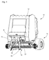
- a round baler 10 shown in figure 1 has a frame 12, a chassis 14, a tongue 16, a pick-up 18, an inlet 20 to a not shown bale chamber and a twine arm assembly 22 shown in detail in figures 2 to 4 .
- the round baler 10 is of an ordinary variable chamber type, which forms cylindrical bales from crop lying on a field; such round balers 10 are widely known.
- a frame 12 is supported on the chassis 14 and can be coupled to a tractor or the like by means of the tongue 16 to be pulled over said field.
- the tongue 16 extends forwardly from a frame cross beam 8 and gets wider from the front to the rear, whereas the wide rear part together with a jackstand 24 and other components like a transmission, steps, hydraulic couplers etc. cover a substantial part above the pick-up 18 and obstruct any access to it.
- the pick-up 18 extends at least over the full width of the round baler 10 or even beyond of it and can be lifted and lowered during operation.
- a non-shown downholder is provided above the pick-up 18 and below the tongue 16, which assists in feeding the crop taken up by the pick-up 18 into the inlet 20.
- the inlet 20 is located behind or downstream of the pick-up 18 and allows crop to enter into a bale chamber, but also twine 26, which is fed to be routed around the peripheral surface of the bale inside the bale chamber, as this is widely known.
- the twine arm assembly 22 is located underneath the cross beam 8 of the frame 12 and underneath the tongue 16 and feeds twine 26 through the inlet 20 into the bale chamber, where it is caught by a rotating bale. Further reference is made to figures 2 to 4 .
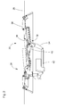
- the twine arm assembly 22 consists of two units 28 and 30, each having a twine arm 32 with a control section 34 and a guide section 36, and a guide member 38, whereas the two units 28, 30 are interconnected by means of a linkage 40 and are commonly operated by an actuator 42. While in this case two units 28 and 30 are present, it could be more or less. These units 28, 30 are substantially of the same design but are arranged in a mirror image fashion.
- the control sections 34 are formed substantially as a straight bar, rod, tube or sheet metal with reinforcements and provided with a front bearing 44 and a rear bearing 46 in the respective end region.
- a short lever 48 is provided, again having a bearing 50 being excentric to the front bearing 44.
- a cantilever 52 being substantially longer than the short lever 48 is attached to the control section 34 of the left control section 34 and extends from latter under an angle of about 90 degrees.
- “Left” and “Right” are meant as seen from the perspective of a person looking into the forward drive direction of the round baler 10.
- a bearing 54 is provided in the free end area of said cantilever 52 .
- Bearings 44 are connected to the frame 12 at the underside of the cross beam 8 and enable the control section 34 to pivot horizontally with respect to the frame 12 about appr. 135 degrees between a position transverse to the driving direction of the round baler 10 and about 45 degrees inclined to it.
- the guide section 36 is formed as a sheet metal with some reinforcement elements and has a twine tube 56, a twine guide and tensioner 58, a bearing 60 and the bearing 46.
- the twine tube 56 is located at the end opposite of the bearing 46. While the bearing 46 connects the guide section 36 to the control section 34, the twine tube 56 is located at the free end of the guide section 36 and extends even beyond that, although this is not really necessary.
- the twine 26 runs to the twine tube 56 and is brought to the surface of the bale.
- the bearing 60 is located between the twine tube 56 and the bearing 46 and the twine guide and tensioner 58 is located quite close to it.
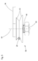
- the twine guide and tensioner 58 comprises two shims 62 of frustrum shape arranged about an axis 64 and pressed onto each other by means of a spring 66, retained and tensioned by a nut 68. Due to the frustrum shape of the shims 62 a V-shaped gap is provided, into which the twine 26 is inserted.
- One of the reinforcements is formed as a catcher 106 with a cavity, which is suitable to receive bearing 88, as this will be described later.
- the guide member 38 comprises two parts 70, 72, which are pivotably connected to each other by means of a bearing 74, and a lock 76.
- Part 70 is pivotably received with one end on a bearing 78 fastened to the frame 12, whereas the bearing 74 is provided at the opposite end.
- Another twine guide and tensioner 58 is arranged on said bearing 78.
- the other part 72 is pivotably received with one end area on bearing 74 and with the other end area on bearing 60.
- the twine arm 32, the guide member 38 and the part of the frame 12 between the bearing 44 and 78 form a triangle with substantially similar length of its edges.
- the lock 76 is provided laterally of the bearing 74 and is able to allow or omit a pivoting movement of the parts 70, 72 on each other.
- the twine guide and tensioner 58 can be activated and deactivated, depending on its position. This is achieved by using a pin 92, another spring 94, a contact area 96 and an activator 98.
- the pin 92 protrudes either the control section 34 or the guide section 36 and is slideably received in a housing 100 fixed to either of the sections 34, 36.
- the pin 92 terminates at one end with the contact area 96 and the spring 94, being formed as a coil spring, extends between the underside of the contact area 96 and the bottom of housing 100, in order to move the contact area 96 away from the housing 100.
- shim 62 is received on the pin 92 to form a gap between the shim 62 and the housing 100, into which the twine 26 can enter.
- the shim 62 is kept in place by a cotter pin 102 and discs 104.
- Activator 98 is fastened either to the frame 12, to the cross beam 8 or e.g. to an extended portion of part 72.
- the linkage 40 is formed as a rod being connected at each end to the bearing 50 on the control sections 34, whereas the bearings 50 and thus the linkage 40 are arranged opposite of a plane through bearings 44 to provide for a mirror image like movement of both units 28, 30. While the linkage 40 shown is of a fixed length, it could also be adjustable in length.
- the actuator 42 is formed as a hydraulic motor, which is attached to the frame 12 at one end and in bearing 54 to the cantilever 52 at the other end.
- the actuator 42 could be also an electric motor and is connected to a power source and a control as this is known.
- Said separating assembly 80 comprises a beam 82 with a knife 84 at one end and a lever arm 86 at the opposite end.
- the beam 82 is journalled on a bearing 88 on the frame 12 in the same plane as the twine arms 32.
- the lever arm 86 extends beyond the bearing 88 and has an eyelet to hold one end of a spring 90, which at the other end is connected to the frame 12.
- the spring 90 is a tension coil spring, which urges the beam 82 about the bearing 88, such, that it pivots outwardly.
- the arrangement of the bearing 88 and of the beam 82 and its lever arm 86 is such, that the right hand control section 36 touches the beam 82, when it moves towards the rest position as shown in figure 2 , by means of a cam 92 and a bearing 91 or similar.
- the extensions of control sections 34 and 36 perpendicular to the plane of movement are designed such, that said bearing 91 may pass the arm 34, but not the arm 36 with the cam 92.
- the tying operation starts from the situation shown in figure 2 , whereas the two parts 70, 72 of the guide member 38 are locked, i.e. they form a substantially straight element.
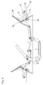
- the actuator 42 When the actuator 42 is extended, it will swing cantilever 52 about the bearing 44 and with it control section 34 of the left unit 30. Due to the connection via linkage 40 also control section 34 of the right unit 28 is pivoted. Since the guide sections 36 of both units 28, 30 are connected via guide member 38 to the frame 12, the movement of the guide section 36 is controlled, such that it assumes the position shown in figure 3 close to the side of the round baler 10. In this position the twine tube 56 gets closest to the bale and brings the twine 26 in connection with it for getting wound about it.
- the twine arms 32 When the actuator 42 is retracted again, the twine arms 32 will again move towards their rest position shown in figure 2 , whereas the right control section 34 moves the beam 82 with its knife 84 through the abutment of bearing 88 in the catcher 106 towards the strands of the twine 26, which accumulate in the center of the round baler 10.
- the knife 84 hits the twine 26 and pushes it against the frame 12, the strands will get separated.
- the spring 90 helps to bring the beam 82 out of the way of the twine arms 32, once tying operation starts.
- the lock 76 is released and the two parts 70, 72 can collapse, such that the guide section 36 assumes the position shown in figure 4 at the side of the round baler 10 and possibly even beyond its lateral edge, where the access is free.
- the twine 26 is inserted into the twine tube 56 it is pulled radially into the twine guide and tensioner 58, where it is tensioned and guided.
- the parts 70, 72 are brought back into their normal position and locked.
Landscapes
- Life Sciences & Earth Sciences (AREA)
- Environmental Sciences (AREA)
- Basic Packing Technique (AREA)
- Binders And Loading Units For Sheaves (AREA)
Abstract
Description
- This invention relates to a twine arm assembly useful in a round baler and having a twine arm with a guide section and a control section, being moveably connected to each other and moveable as a unit between a tying position and a rest position, and having a guide member connected to one section and to a round baler.
-
DE 197 42 003 A1 discloses in itsfigures 4 to 7 a twine arm assembly with two carriers each for two twine arms, whereas both carriers are pivoted by a motor and controlled by a linkage connected otherends to a frame of a round baler. The twine arms are moveable between a rest position close to the center area of the round baler and underneath a tonque and a twine delivery position close to the side area of the round baler. - The problem this invention is based on is seen in the difficulties for an operator to insert twine into the twine arm, when new twine shall be used.
- This problem is solved in an innovative way by means of the teaching of claim 1, whereas advantageous features further developing the invention are given in the claims related to claim 1.
- By means of this teaching the guide member can be brought into a position or discoupled or changed or altered in any other way such, that the guide section can be brought into a position, where twine can be inserted easily. Such a position maybe given at the side area of the round baler, which is easy to reach. Also, the guide section may be pivoted or slit during insertion of the twine, to make insertion as convenient for an operator. The guide member can be collapsable, foldable, adjustable like a telescope, or consist of a flexible means like a rope, a wire, a chain or the like. Another way would be to provide for a coupling of the guide member on the control or guide section, which can be discoupled easily and make the guide section freely moveable. Movement of the guide section may happen in or transverse to the twine arm movement plane during operation, i.e. horizontally or vertically. The control section may consist of several components or be of a single unit.
- In order to assure, that the guide member is stable during operation, but flexible, when the twine shall be inserted, a lock is provided. Said lock may be formed as a bolt, pin, spring pin or the like protruding a hole, a spring loaded detent, a simple motor or sort of a self-locking positive lock between the two parts.
- A simple design for connecting the two parts is a bearing, which makes both parts pivotable on each other. Said bearing may include the lock or not.
- When the guide section is arranged between the guide member and the control section, it follows, that the guide member is provided at the outside of the whole assembly, where it is easily accessible for bringing the assembly into a condition, where the twine can be fed.
- Tying cycle is shortened if two units or sets are provided for delivering twine and even more, if each set has two twine outlets, rather than one only.
- Synchronisation of the movement of both twine guide sections and control sections is achieved, if both control sections are connected among each other by any kind of a linkage, like a rod, a cable, fluid line, etc.
- In order to save parts and costs and to increase reliability it is helpful to have one actuator acting upon either of the control sections, which transmits its movement to the other control section by means of the linkage. Such an actuator may be a hydraulic, electric or pneumatic motor or even a mechanical lever.
- In order to even more facilitate the insertion of twine into the guide section twine guide member are provided on the guide section and/or on the guide member, which have an element biased against a fixed or moveable element, between which a gap is formed to receive twine. These elements can be shims, discs, plates, etc. which are under the pressure of a spring and which abut other shims, etc. or one of the sections or the guide member, a frame, etc. and form a gap, preferably in V-shape, into which a twine strand can be inserted radially, rather than through an eyelet, a hole, a tube or the like.
- Deactivating the tensioner in the twine guide and tensioner, helps to feed the twine into the bale chamber, since it does not create any resistance. Such deactivation may happen manually or mechanically, if the twine guide and tensioner during its movement abuts a stop, cam, or the like; or it may be deactivated electrically.
- Round balers for agricultural or industrial products of variable or fix chamber type are very suitable for one or more twine arm assemblies according to either of the precedings claims.
- Heretoafter one embodiment of the invention is described in more detail and in relation to the drawing. It is shown in:
- Fig. 1
- a front perspective view of a round baler having a twine arm assembly,
- Fig. 2
- the twine arm assembly in top view in a rest position,
- Fig. 3
- the twine arm assembly in top view in an operating position,
- Fig. 4
- the twine arm assembly in top view in the rest position, whereas a guide member of it is in a service condition,
- Fig. 5
- a twine guide means in a side view,
- Fig. 6
- a twine guide and tensioner in a deactivated position and
- Fig. 7
- the twine guide and tensioner in an activated position.
- A
round baler 10 shown infigure 1 has aframe 12, achassis 14, atongue 16, a pick-up 18, aninlet 20 to a not shown bale chamber and atwine arm assembly 22 shown in detail infigures 2 to 4 . - The
round baler 10 is of an ordinary variable chamber type, which forms cylindrical bales from crop lying on a field;such round balers 10 are widely known. - A
frame 12 is supported on thechassis 14 and can be coupled to a tractor or the like by means of thetongue 16 to be pulled over said field. Thetongue 16 extends forwardly from aframe cross beam 8 and gets wider from the front to the rear, whereas the wide rear part together with ajackstand 24 and other components like a transmission, steps, hydraulic couplers etc. cover a substantial part above the pick-up 18 and obstruct any access to it. - The pick-
up 18 extends at least over the full width of theround baler 10 or even beyond of it and can be lifted and lowered during operation. Usually a non-shown downholder is provided above the pick-up 18 and below thetongue 16, which assists in feeding the crop taken up by the pick-up 18 into theinlet 20. When the pick-up 18 is in an upper position and/or when crop is on the pick-up 18 there is very little space between the pick-up 18 and the underside of thetongue 16 and thecross beam 8 of theframe 12. - The
inlet 20 is located behind or downstream of the pick-up 18 and allows crop to enter into a bale chamber, but alsotwine 26, which is fed to be routed around the peripheral surface of the bale inside the bale chamber, as this is widely known. - The
twine arm assembly 22 is located underneath thecross beam 8 of theframe 12 and underneath thetongue 16 and feedstwine 26 through theinlet 20 into the bale chamber, where it is caught by a rotating bale. Further reference is made tofigures 2 to 4 . - According to
figure 2 thetwine arm assembly 22 consists of twounits twine arm 32 with acontrol section 34 and aguide section 36, and aguide member 38, whereas the twounits linkage 40 and are commonly operated by anactuator 42. While in this case twounits units - The
control sections 34 are formed substantially as a straight bar, rod, tube or sheet metal with reinforcements and provided with a front bearing 44 and a rear bearing 46 in the respective end region. In the front end region ashort lever 48 is provided, again having a bearing 50 being excentric to the front bearing 44. In addition acantilever 52 being substantially longer than theshort lever 48 is attached to thecontrol section 34 of theleft control section 34 and extends from latter under an angle of about 90 degrees. "Left" and "Right" are meant as seen from the perspective of a person looking into the forward drive direction of theround baler 10. In the free end area of said cantilever 52 abearing 54 is provided.Bearings 44 are connected to theframe 12 at the underside of thecross beam 8 and enable thecontrol section 34 to pivot horizontally with respect to theframe 12 about appr. 135 degrees between a position transverse to the driving direction of theround baler 10 and about 45 degrees inclined to it. - The
guide section 36 is formed as a sheet metal with some reinforcement elements and has atwine tube 56, a twine guide andtensioner 58, abearing 60 and thebearing 46. Thetwine tube 56 is located at the end opposite of thebearing 46. While thebearing 46 connects theguide section 36 to thecontrol section 34, thetwine tube 56 is located at the free end of theguide section 36 and extends even beyond that, although this is not really necessary. Thetwine 26 runs to thetwine tube 56 and is brought to the surface of the bale. Thebearing 60 is located between thetwine tube 56 and thebearing 46 and the twine guide andtensioner 58 is located quite close to it. The twine guide andtensioner 58 comprises twoshims 62 of frustrum shape arranged about anaxis 64 and pressed onto each other by means of aspring 66, retained and tensioned by anut 68. Due to the frustrum shape of the shims 62 a V-shaped gap is provided, into which thetwine 26 is inserted. One of the reinforcements is formed as acatcher 106 with a cavity, which is suitable to receivebearing 88, as this will be described later. - The
guide member 38 comprises twoparts bearing 74, and alock 76.Part 70 is pivotably received with one end on abearing 78 fastened to theframe 12, whereas thebearing 74 is provided at the opposite end. Another twine guide andtensioner 58 is arranged on saidbearing 78. Theother part 72 is pivotably received with one end area on bearing 74 and with the other end area on bearing 60. In the situation shown infigure 3 thetwine arm 32, theguide member 38 and the part of theframe 12 between the bearing 44 and 78 form a triangle with substantially similar length of its edges. Thelock 76 is provided laterally of thebearing 74 and is able to allow or omit a pivoting movement of theparts - As it is shown in
figures 6 and 7 , the twine guide andtensioner 58 can be activated and deactivated, depending on its position. This is achieved by using apin 92, anotherspring 94, acontact area 96 and anactivator 98. Thepin 92 protrudes either thecontrol section 34 or theguide section 36 and is slideably received in ahousing 100 fixed to either of thesections pin 92 terminates at one end with thecontact area 96 and thespring 94, being formed as a coil spring, extends between the underside of thecontact area 96 and the bottom ofhousing 100, in order to move thecontact area 96 away from thehousing 100. On the other side of thehousing 100shim 62 is received on thepin 92 to form a gap between theshim 62 and thehousing 100, into which thetwine 26 can enter. Theshim 62 is kept in place by acotter pin 102 anddiscs 104.Activator 98 is fastened either to theframe 12, to thecross beam 8 or e.g. to an extended portion ofpart 72. It is only important to locate theactivator 98 such, that it abuts thecontact area 96, when thetwine arm assembly 22 assumes its tying starting position, and depresses thepin 92 by contacting thecontact area 96 against the virtue of thespring 94, such that the gap betweendisc 62 and the underside of thehousing 100 gets bigger and lets thetwine 26 pass without resistance. - The
linkage 40 is formed as a rod being connected at each end to thebearing 50 on thecontrol sections 34, whereas thebearings 50 and thus thelinkage 40 are arranged opposite of a plane throughbearings 44 to provide for a mirror image like movement of bothunits linkage 40 shown is of a fixed length, it could also be adjustable in length. - The
actuator 42 is formed as a hydraulic motor, which is attached to theframe 12 at one end and in bearing 54 to thecantilever 52 at the other end. Theactuator 42 could be also an electric motor and is connected to a power source and a control as this is known. - Finally a separating
assembly 80 is provided to cut thetwine 26, when the tying cycle is over. Said separatingassembly 80 comprises abeam 82 with aknife 84 at one end and alever arm 86 at the opposite end. Thebeam 82 is journalled on abearing 88 on theframe 12 in the same plane as thetwine arms 32. Thelever arm 86 extends beyond thebearing 88 and has an eyelet to hold one end of aspring 90, which at the other end is connected to theframe 12. Thespring 90 is a tension coil spring, which urges thebeam 82 about thebearing 88, such, that it pivots outwardly. The arrangement of thebearing 88 and of thebeam 82 and itslever arm 86 is such, that the righthand control section 36 touches thebeam 82, when it moves towards the rest position as shown infigure 2 , by means of acam 92 and a bearing 91 or similar. The extensions ofcontrol sections arm 34, but not thearm 36 with thecam 92. - In the light of the aforesaid structural description the function of the
twine arm assembly 22 is described as follows. - The tying operation starts from the situation shown in
figure 2 , whereas the twoparts guide member 38 are locked, i.e. they form a substantially straight element. When theactuator 42 is extended, it will swingcantilever 52 about thebearing 44 and with it controlsection 34 of theleft unit 30. Due to the connection vialinkage 40 also controlsection 34 of theright unit 28 is pivoted. Since theguide sections 36 of bothunits guide member 38 to theframe 12, the movement of theguide section 36 is controlled, such that it assumes the position shown infigure 3 close to the side of theround baler 10. In this position thetwine tube 56 gets closest to the bale and brings thetwine 26 in connection with it for getting wound about it. When theactuator 42 is retracted again, thetwine arms 32 will again move towards their rest position shown infigure 2 , whereas theright control section 34 moves thebeam 82 with itsknife 84 through the abutment of bearing 88 in thecatcher 106 towards the strands of thetwine 26, which accumulate in the center of theround baler 10. When theknife 84 hits thetwine 26 and pushes it against theframe 12, the strands will get separated. Thespring 90 helps to bring thebeam 82 out of the way of thetwine arms 32, once tying operation starts. - In order to insert
twine 26 into thetwine tube 56 in the rest position shown infigure 2 , thelock 76 is released and the twoparts guide section 36 assumes the position shown infigure 4 at the side of theround baler 10 and possibly even beyond its lateral edge, where the access is free. When thetwine 26 is inserted into thetwine tube 56 it is pulled radially into the twine guide andtensioner 58, where it is tensioned and guided. Once thetwine 26 is inserted and pulled through theshort twine tube 56, theparts
Claims (10)
- Twine arm assembly (22) useful in a round baler (10) and having a twine arm (32) with a guide section (36) and a control section (34), being moveably connected to each other and moveable as a unit between a tying position and a rest position, and having a guide member (38) connected to one section (36), characterized in that the guide member (38) itself or either of its connections can be varied or disconnected such, that the respective section 36 can be brought into a position different from the tying or rest position.
- Twine arm assembly according to claim 1, characterized in that the guide member (38) contains two parts (70), (72) and a lock (76), whereas the lock (76) either rigidly connects the two parts (70), (72) to each other or allows a relative movement between them.
- Twine arm assembly according to claim 1 or 2, characterized in that the guide member (38) contains two parts (70), (72) connected to each other in a bearing (74).
- Twine arm assembly according to either of the preceding claims, characterized in that the guide section (36) is arranged between the guide member (38) and the control section (34).
- Twine arm assembly according to either of the preceding claims, characterized in that two units (28), (30), each consisting of a guide section (36), a control section (34) and a guide member (38) are provided in a mirror image fashion.
- Twine arm assembly according to claim 5, characterized in that the control sections (34) of both units (28), (30) are interconnected by a linkage (40).
- Twine arm assembly according to claim 5 or 6, characterized in that an actuator (42) is provided acting upon either of the control sections (34).
- Twine arm assembly according to either of the preceding claims, characterized in that a twine guide and tensioner (58) is provided on the guide section (36) and/or on the guide member (38), whereas the twine guide and tensioner (58) has an element (62) biased against a fixed or moveable element (62), between which a gap is formed to receive twine (26).
- Twine arm assembly according to either of the preceding claims, characterized in that the tensioning effect of the twine guide and tensioner (58) may be suspended at the beginning of a tying cycle.
- Round baler (10) equipped with one or more twine arm assemblies (22) according to either of the preceding claims.
Priority Applications (4)
| Application Number | Priority Date | Filing Date | Title |
|---|---|---|---|
| EP08164926.1A EP2165595B1 (en) | 2008-09-23 | 2008-09-23 | Twine arm assembly |
| PL08164926T PL2165595T3 (en) | 2008-09-23 | 2008-09-23 | Twine arm assembly |
| EA200901096A EA017244B1 (en) | 2008-09-23 | 2009-09-09 | Twine arm assembly |
| US12/560,745 US8056472B2 (en) | 2008-09-23 | 2009-09-16 | Twine arm assembly |
Applications Claiming Priority (1)
| Application Number | Priority Date | Filing Date | Title |
|---|---|---|---|
| EP08164926.1A EP2165595B1 (en) | 2008-09-23 | 2008-09-23 | Twine arm assembly |
Publications (2)
| Publication Number | Publication Date |
|---|---|
| EP2165595A1 true EP2165595A1 (en) | 2010-03-24 |
| EP2165595B1 EP2165595B1 (en) | 2014-05-14 |
Family
ID=40352338
Family Applications (1)
| Application Number | Title | Priority Date | Filing Date |
|---|---|---|---|
| EP08164926.1A Active EP2165595B1 (en) | 2008-09-23 | 2008-09-23 | Twine arm assembly |
Country Status (4)
| Country | Link |
|---|---|
| US (1) | US8056472B2 (en) |
| EP (1) | EP2165595B1 (en) |
| EA (1) | EA017244B1 (en) |
| PL (1) | PL2165595T3 (en) |
Families Citing this family (2)
| Publication number | Priority date | Publication date | Assignee | Title |
|---|---|---|---|---|
| US10048047B2 (en) * | 2014-08-06 | 2018-08-14 | Alba Manufacturing Corp. | Explosive booster |
| CN113968389A (en) * | 2021-12-02 | 2022-01-25 | 东光县恒信包装机械厂 | Binding rope structure for carton packing belt |
Citations (6)
| Publication number | Priority date | Publication date | Assignee | Title |
|---|---|---|---|---|
| US4715175A (en) * | 1984-12-11 | 1987-12-29 | Klockner-Humboldt-Deutz Ag Zweigniederlassung Fahr | Binder-twine guide and cutter mechanism for roll-baler |
| US5388504A (en) * | 1993-08-23 | 1995-02-14 | Agco Corporation | Twine wrap control for round baler |
| US5465658A (en) * | 1994-05-02 | 1995-11-14 | New Holland North America, Inc. | Twine cutting apparatus for round baler |
| DE19742003A1 (en) | 1997-09-24 | 1999-04-15 | Deere & Co | Binder and round bale press |
| US20030089560A1 (en) * | 2001-10-30 | 2003-05-15 | Jean Viaud | Round baler binding arrangement including twine tension control |
| US6769353B1 (en) * | 2003-02-28 | 2004-08-03 | New Holland North America, Inc. | Four twine tube round baler twine system |
Family Cites Families (5)
| Publication number | Priority date | Publication date | Assignee | Title |
|---|---|---|---|---|
| US2604844A (en) * | 1946-11-29 | 1952-07-29 | Deere Mfg Co | Safety device for withdrawing needles from bale cases |
| DE85817T1 (en) * | 1982-02-10 | 1984-01-05 | John Deere S.A., 45011 Orleans | TWO-ARMED TIE DEVICE FOR ROUND BALING PRESS. |
| SU1303071A1 (en) * | 1985-06-07 | 1987-04-15 | Всесоюзный Научно-Исследовательский Институт Льна | Binding apparatus |
| US5437226A (en) * | 1994-05-02 | 1995-08-01 | New Holland North America, Inc. | Twine cutter for a round baler |
| US7104189B2 (en) * | 2004-12-27 | 2006-09-12 | Vermeer Manufacturing Company | Twine restrictor |
-
2008
- 2008-09-23 PL PL08164926T patent/PL2165595T3/en unknown
- 2008-09-23 EP EP08164926.1A patent/EP2165595B1/en active Active
-
2009
- 2009-09-09 EA EA200901096A patent/EA017244B1/en not_active IP Right Cessation
- 2009-09-16 US US12/560,745 patent/US8056472B2/en active Active
Patent Citations (6)
| Publication number | Priority date | Publication date | Assignee | Title |
|---|---|---|---|---|
| US4715175A (en) * | 1984-12-11 | 1987-12-29 | Klockner-Humboldt-Deutz Ag Zweigniederlassung Fahr | Binder-twine guide and cutter mechanism for roll-baler |
| US5388504A (en) * | 1993-08-23 | 1995-02-14 | Agco Corporation | Twine wrap control for round baler |
| US5465658A (en) * | 1994-05-02 | 1995-11-14 | New Holland North America, Inc. | Twine cutting apparatus for round baler |
| DE19742003A1 (en) | 1997-09-24 | 1999-04-15 | Deere & Co | Binder and round bale press |
| US20030089560A1 (en) * | 2001-10-30 | 2003-05-15 | Jean Viaud | Round baler binding arrangement including twine tension control |
| US6769353B1 (en) * | 2003-02-28 | 2004-08-03 | New Holland North America, Inc. | Four twine tube round baler twine system |
Also Published As
| Publication number | Publication date |
|---|---|
| US8056472B2 (en) | 2011-11-15 |
| EA017244B1 (en) | 2012-11-30 |
| EA200901096A1 (en) | 2010-04-30 |
| PL2165595T3 (en) | 2014-09-30 |
| US20100251910A1 (en) | 2010-10-07 |
| EP2165595B1 (en) | 2014-05-14 |
Similar Documents
| Publication | Publication Date | Title |
|---|---|---|
| US8656832B2 (en) | Round baler having lateral guides for the compression belt | |
| US7181900B2 (en) | Netwrap feed and cut mechanism | |
| CN108781780B (en) | Baffle float system for a baler | |
| US4167844A (en) | Automatic twine wrapping apparatus | |
| EP3461322B1 (en) | System and method for recompressing round bales into square bales | |
| US4457226A (en) | Twine-wrapping mechanism for a large round baler | |
| US4516389A (en) | Round hay baling machine | |
| EP3461321B1 (en) | System and method for recompressing round bales into square bales | |
| US6810650B2 (en) | Replaceable windguard tines for a round baler | |
| EP3461318B1 (en) | System and method for recompressing round bales into square bales | |
| EP1842418A1 (en) | Round baler bale ejecting arrangement | |
| EP3461319B1 (en) | System and method for recompressing round bales into square bales | |
| EP2165595B1 (en) | Twine arm assembly | |
| EP2353364A1 (en) | Agricultural harvesting pickup apparatus | |
| EP3461320B1 (en) | System and method for recompressing round bales into square bales | |
| US4062279A (en) | Twine wrapping mechanism for a roll forming machine | |
| US6883422B2 (en) | Round baler binding arrangement including twine tension control | |
| CA1089289A (en) | Independently operated twine knives | |
| US7024989B2 (en) | Arrangement to support the ejection of a cylindrical bale | |
| US20260076309A1 (en) | Twin roller windguard | |
| EP0085817B1 (en) | Binding device with two arms for a baler for cylindrical bales | |
| US4502646A (en) | Twine tensioner for large round bale twine-wrapping mechanism | |
| US5950530A (en) | Arrangement and process for the securing of twine ends | |
| JP4824988B2 (en) | Combine weeding equipment | |
| GB2150073A (en) | Baler |
Legal Events
| Date | Code | Title | Description |
|---|---|---|---|
| PUAI | Public reference made under article 153(3) epc to a published international application that has entered the european phase |
Free format text: ORIGINAL CODE: 0009012 |
|
| AK | Designated contracting states |
Kind code of ref document: A1 Designated state(s): AT BE BG CH CY CZ DE DK EE ES FI FR GB GR HR HU IE IS IT LI LT LU LV MC MT NL NO PL PT RO SE SI SK TR |
|
| AX | Request for extension of the european patent |
Extension state: AL BA MK RS |
|
| 17P | Request for examination filed |
Effective date: 20100924 |
|
| 17Q | First examination report despatched |
Effective date: 20101027 |
|
| AKX | Designation fees paid |
Designated state(s): AT BE BG CH CY CZ DE DK EE ES FI FR GB GR HR HU IE IS IT LI LT LU LV MC MT NL NO PL PT RO SE SI SK TR |
|
| GRAP | Despatch of communication of intention to grant a patent |
Free format text: ORIGINAL CODE: EPIDOSNIGR1 |
|
| INTG | Intention to grant announced |
Effective date: 20131205 |
|
| GRAS | Grant fee paid |
Free format text: ORIGINAL CODE: EPIDOSNIGR3 |
|
| GRAA | (expected) grant |
Free format text: ORIGINAL CODE: 0009210 |
|
| AK | Designated contracting states |
Kind code of ref document: B1 Designated state(s): AT BE BG CH CY CZ DE DK EE ES FI FR GB GR HR HU IE IS IT LI LT LU LV MC MT NL NO PL PT RO SE SI SK TR |
|
| REG | Reference to a national code |
Ref country code: GB Ref legal event code: FG4D |
|
| REG | Reference to a national code |
Ref country code: AT Ref legal event code: REF Ref document number: 667523 Country of ref document: AT Kind code of ref document: T Effective date: 20140615 |
|
| REG | Reference to a national code |
Ref country code: DE Ref legal event code: R096 Ref document number: 602008032230 Country of ref document: DE Effective date: 20140618 Ref country code: IE Ref legal event code: FG4D |
|
| REG | Reference to a national code |
Ref country code: NL Ref legal event code: T3 |
|
| REG | Reference to a national code |
Ref country code: PL Ref legal event code: T3 |
|
| REG | Reference to a national code |
Ref country code: AT Ref legal event code: MK05 Ref document number: 667523 Country of ref document: AT Kind code of ref document: T Effective date: 20140514 |
|
| REG | Reference to a national code |
Ref country code: LT Ref legal event code: MG4D |
|
| PG25 | Lapsed in a contracting state [announced via postgrant information from national office to epo] |
Ref country code: IS Free format text: LAPSE BECAUSE OF FAILURE TO SUBMIT A TRANSLATION OF THE DESCRIPTION OR TO PAY THE FEE WITHIN THE PRESCRIBED TIME-LIMIT Effective date: 20140914 Ref country code: FI Free format text: LAPSE BECAUSE OF FAILURE TO SUBMIT A TRANSLATION OF THE DESCRIPTION OR TO PAY THE FEE WITHIN THE PRESCRIBED TIME-LIMIT Effective date: 20140514 Ref country code: LT Free format text: LAPSE BECAUSE OF FAILURE TO SUBMIT A TRANSLATION OF THE DESCRIPTION OR TO PAY THE FEE WITHIN THE PRESCRIBED TIME-LIMIT Effective date: 20140514 Ref country code: CY Free format text: LAPSE BECAUSE OF FAILURE TO SUBMIT A TRANSLATION OF THE DESCRIPTION OR TO PAY THE FEE WITHIN THE PRESCRIBED TIME-LIMIT Effective date: 20140514 Ref country code: GR Free format text: LAPSE BECAUSE OF FAILURE TO SUBMIT A TRANSLATION OF THE DESCRIPTION OR TO PAY THE FEE WITHIN THE PRESCRIBED TIME-LIMIT Effective date: 20140815 Ref country code: NO Free format text: LAPSE BECAUSE OF FAILURE TO SUBMIT A TRANSLATION OF THE DESCRIPTION OR TO PAY THE FEE WITHIN THE PRESCRIBED TIME-LIMIT Effective date: 20140814 |
|
| PG25 | Lapsed in a contracting state [announced via postgrant information from national office to epo] |
Ref country code: HR Free format text: LAPSE BECAUSE OF FAILURE TO SUBMIT A TRANSLATION OF THE DESCRIPTION OR TO PAY THE FEE WITHIN THE PRESCRIBED TIME-LIMIT Effective date: 20140514 Ref country code: AT Free format text: LAPSE BECAUSE OF FAILURE TO SUBMIT A TRANSLATION OF THE DESCRIPTION OR TO PAY THE FEE WITHIN THE PRESCRIBED TIME-LIMIT Effective date: 20140514 Ref country code: LV Free format text: LAPSE BECAUSE OF FAILURE TO SUBMIT A TRANSLATION OF THE DESCRIPTION OR TO PAY THE FEE WITHIN THE PRESCRIBED TIME-LIMIT Effective date: 20140514 Ref country code: ES Free format text: LAPSE BECAUSE OF FAILURE TO SUBMIT A TRANSLATION OF THE DESCRIPTION OR TO PAY THE FEE WITHIN THE PRESCRIBED TIME-LIMIT Effective date: 20140514 Ref country code: SE Free format text: LAPSE BECAUSE OF FAILURE TO SUBMIT A TRANSLATION OF THE DESCRIPTION OR TO PAY THE FEE WITHIN THE PRESCRIBED TIME-LIMIT Effective date: 20140514 |
|
| PG25 | Lapsed in a contracting state [announced via postgrant information from national office to epo] |
Ref country code: PT Free format text: LAPSE BECAUSE OF FAILURE TO SUBMIT A TRANSLATION OF THE DESCRIPTION OR TO PAY THE FEE WITHIN THE PRESCRIBED TIME-LIMIT Effective date: 20140915 |
|
| PGFP | Annual fee paid to national office [announced via postgrant information from national office to epo] |
Ref country code: IT Payment date: 20140922 Year of fee payment: 7 |
|
| PG25 | Lapsed in a contracting state [announced via postgrant information from national office to epo] |
Ref country code: BE Free format text: LAPSE BECAUSE OF FAILURE TO SUBMIT A TRANSLATION OF THE DESCRIPTION OR TO PAY THE FEE WITHIN THE PRESCRIBED TIME-LIMIT Effective date: 20140514 Ref country code: CZ Free format text: LAPSE BECAUSE OF FAILURE TO SUBMIT A TRANSLATION OF THE DESCRIPTION OR TO PAY THE FEE WITHIN THE PRESCRIBED TIME-LIMIT Effective date: 20140514 Ref country code: DK Free format text: LAPSE BECAUSE OF FAILURE TO SUBMIT A TRANSLATION OF THE DESCRIPTION OR TO PAY THE FEE WITHIN THE PRESCRIBED TIME-LIMIT Effective date: 20140514 Ref country code: EE Free format text: LAPSE BECAUSE OF FAILURE TO SUBMIT A TRANSLATION OF THE DESCRIPTION OR TO PAY THE FEE WITHIN THE PRESCRIBED TIME-LIMIT Effective date: 20140514 Ref country code: SK Free format text: LAPSE BECAUSE OF FAILURE TO SUBMIT A TRANSLATION OF THE DESCRIPTION OR TO PAY THE FEE WITHIN THE PRESCRIBED TIME-LIMIT Effective date: 20140514 Ref country code: RO Free format text: LAPSE BECAUSE OF FAILURE TO SUBMIT A TRANSLATION OF THE DESCRIPTION OR TO PAY THE FEE WITHIN THE PRESCRIBED TIME-LIMIT Effective date: 20140514 |
|
| REG | Reference to a national code |
Ref country code: DE Ref legal event code: R097 Ref document number: 602008032230 Country of ref document: DE |
|
| PGFP | Annual fee paid to national office [announced via postgrant information from national office to epo] |
Ref country code: NL Payment date: 20140926 Year of fee payment: 7 |
|
| PLBE | No opposition filed within time limit |
Free format text: ORIGINAL CODE: 0009261 |
|
| STAA | Information on the status of an ep patent application or granted ep patent |
Free format text: STATUS: NO OPPOSITION FILED WITHIN TIME LIMIT |
|
| 26N | No opposition filed |
Effective date: 20150217 |
|
| PG25 | Lapsed in a contracting state [announced via postgrant information from national office to epo] |
Ref country code: MC Free format text: LAPSE BECAUSE OF FAILURE TO SUBMIT A TRANSLATION OF THE DESCRIPTION OR TO PAY THE FEE WITHIN THE PRESCRIBED TIME-LIMIT Effective date: 20140514 Ref country code: LU Free format text: LAPSE BECAUSE OF FAILURE TO SUBMIT A TRANSLATION OF THE DESCRIPTION OR TO PAY THE FEE WITHIN THE PRESCRIBED TIME-LIMIT Effective date: 20140923 |
|
| REG | Reference to a national code |
Ref country code: CH Ref legal event code: PL |
|
| GBPC | Gb: european patent ceased through non-payment of renewal fee |
Effective date: 20140923 |
|
| REG | Reference to a national code |
Ref country code: DE Ref legal event code: R097 Ref document number: 602008032230 Country of ref document: DE Effective date: 20150217 |
|
| REG | Reference to a national code |
Ref country code: IE Ref legal event code: MM4A |
|
| PG25 | Lapsed in a contracting state [announced via postgrant information from national office to epo] |
Ref country code: GB Free format text: LAPSE BECAUSE OF NON-PAYMENT OF DUE FEES Effective date: 20140923 Ref country code: LI Free format text: LAPSE BECAUSE OF NON-PAYMENT OF DUE FEES Effective date: 20140930 Ref country code: SI Free format text: LAPSE BECAUSE OF FAILURE TO SUBMIT A TRANSLATION OF THE DESCRIPTION OR TO PAY THE FEE WITHIN THE PRESCRIBED TIME-LIMIT Effective date: 20140514 Ref country code: CH Free format text: LAPSE BECAUSE OF NON-PAYMENT OF DUE FEES Effective date: 20140930 |
|
| PG25 | Lapsed in a contracting state [announced via postgrant information from national office to epo] |
Ref country code: IE Free format text: LAPSE BECAUSE OF NON-PAYMENT OF DUE FEES Effective date: 20140923 |
|
| PG25 | Lapsed in a contracting state [announced via postgrant information from national office to epo] |
Ref country code: IT Free format text: LAPSE BECAUSE OF NON-PAYMENT OF DUE FEES Effective date: 20150923 |
|
| PG25 | Lapsed in a contracting state [announced via postgrant information from national office to epo] |
Ref country code: BG Free format text: LAPSE BECAUSE OF FAILURE TO SUBMIT A TRANSLATION OF THE DESCRIPTION OR TO PAY THE FEE WITHIN THE PRESCRIBED TIME-LIMIT Effective date: 20140514 |
|
| REG | Reference to a national code |
Ref country code: NL Ref legal event code: MM Effective date: 20151001 |
|
| PG25 | Lapsed in a contracting state [announced via postgrant information from national office to epo] |
Ref country code: MT Free format text: LAPSE BECAUSE OF FAILURE TO SUBMIT A TRANSLATION OF THE DESCRIPTION OR TO PAY THE FEE WITHIN THE PRESCRIBED TIME-LIMIT Effective date: 20140514 |
|
| PG25 | Lapsed in a contracting state [announced via postgrant information from national office to epo] |
Ref country code: HU Free format text: LAPSE BECAUSE OF FAILURE TO SUBMIT A TRANSLATION OF THE DESCRIPTION OR TO PAY THE FEE WITHIN THE PRESCRIBED TIME-LIMIT; INVALID AB INITIO Effective date: 20080923 Ref country code: TR Free format text: LAPSE BECAUSE OF FAILURE TO SUBMIT A TRANSLATION OF THE DESCRIPTION OR TO PAY THE FEE WITHIN THE PRESCRIBED TIME-LIMIT Effective date: 20140514 |
|
| PG25 | Lapsed in a contracting state [announced via postgrant information from national office to epo] |
Ref country code: NL Free format text: LAPSE BECAUSE OF NON-PAYMENT OF DUE FEES Effective date: 20151001 |
|
| REG | Reference to a national code |
Ref country code: FR Ref legal event code: PLFP Year of fee payment: 9 |
|
| REG | Reference to a national code |
Ref country code: FR Ref legal event code: PLFP Year of fee payment: 10 |
|
| REG | Reference to a national code |
Ref country code: FR Ref legal event code: PLFP Year of fee payment: 11 |
|
| PGFP | Annual fee paid to national office [announced via postgrant information from national office to epo] |
Ref country code: FR Payment date: 20240925 Year of fee payment: 17 |
|
| PGFP | Annual fee paid to national office [announced via postgrant information from national office to epo] |
Ref country code: PL Payment date: 20240902 Year of fee payment: 17 |
|
| PGFP | Annual fee paid to national office [announced via postgrant information from national office to epo] |
Ref country code: DE Payment date: 20250820 Year of fee payment: 18 |