EP2164562B1 - Stimulation endocardiaque en relation avec des anomalies de conduction - Google Patents
Stimulation endocardiaque en relation avec des anomalies de conduction Download PDFInfo
- Publication number
- EP2164562B1 EP2164562B1 EP08796045.6A EP08796045A EP2164562B1 EP 2164562 B1 EP2164562 B1 EP 2164562B1 EP 08796045 A EP08796045 A EP 08796045A EP 2164562 B1 EP2164562 B1 EP 2164562B1
- Authority
- EP
- European Patent Office
- Prior art keywords
- pacing
- electrodes
- electrode
- lead
- heart
- Prior art date
- Legal status (The legal status is an assumption and is not a legal conclusion. Google has not performed a legal analysis and makes no representation as to the accuracy of the status listed.)
- Not-in-force
Links
Images


Classifications
-
- A—HUMAN NECESSITIES
- A61—MEDICAL OR VETERINARY SCIENCE; HYGIENE
- A61N—ELECTROTHERAPY; MAGNETOTHERAPY; RADIATION THERAPY; ULTRASOUND THERAPY
- A61N1/00—Electrotherapy; Circuits therefor
- A61N1/18—Applying electric currents by contact electrodes
- A61N1/32—Applying electric currents by contact electrodes alternating or intermittent currents
- A61N1/36—Applying electric currents by contact electrodes alternating or intermittent currents for stimulation
- A61N1/362—Heart stimulators
- A61N1/3627—Heart stimulators for treating a mechanical deficiency of the heart, e.g. congestive heart failure or cardiomyopathy
-
- A—HUMAN NECESSITIES
- A61—MEDICAL OR VETERINARY SCIENCE; HYGIENE
- A61N—ELECTROTHERAPY; MAGNETOTHERAPY; RADIATION THERAPY; ULTRASOUND THERAPY
- A61N1/00—Electrotherapy; Circuits therefor
- A61N1/18—Applying electric currents by contact electrodes
- A61N1/32—Applying electric currents by contact electrodes alternating or intermittent currents
- A61N1/36—Applying electric currents by contact electrodes alternating or intermittent currents for stimulation
- A61N1/362—Heart stimulators
- A61N1/365—Heart stimulators controlled by a physiological parameter, e.g. heart potential
- A61N1/36514—Heart stimulators controlled by a physiological parameter, e.g. heart potential controlled by a physiological quantity other than heart potential, e.g. blood pressure
- A61N1/36564—Heart stimulators controlled by a physiological parameter, e.g. heart potential controlled by a physiological quantity other than heart potential, e.g. blood pressure controlled by blood pressure
-
- A—HUMAN NECESSITIES
- A61—MEDICAL OR VETERINARY SCIENCE; HYGIENE
- A61N—ELECTROTHERAPY; MAGNETOTHERAPY; RADIATION THERAPY; ULTRASOUND THERAPY
- A61N1/00—Electrotherapy; Circuits therefor
- A61N1/18—Applying electric currents by contact electrodes
- A61N1/32—Applying electric currents by contact electrodes alternating or intermittent currents
- A61N1/36—Applying electric currents by contact electrodes alternating or intermittent currents for stimulation
- A61N1/362—Heart stimulators
- A61N1/365—Heart stimulators controlled by a physiological parameter, e.g. heart potential
- A61N1/368—Heart stimulators controlled by a physiological parameter, e.g. heart potential comprising more than one electrode co-operating with different heart regions
- A61N1/3684—Heart stimulators controlled by a physiological parameter, e.g. heart potential comprising more than one electrode co-operating with different heart regions for stimulating the heart at multiple sites of the ventricle or the atrium
- A61N1/36842—Multi-site stimulation in the same chamber
-
- A—HUMAN NECESSITIES
- A61—MEDICAL OR VETERINARY SCIENCE; HYGIENE
- A61N—ELECTROTHERAPY; MAGNETOTHERAPY; RADIATION THERAPY; ULTRASOUND THERAPY
- A61N1/00—Electrotherapy; Circuits therefor
- A61N1/18—Applying electric currents by contact electrodes
- A61N1/32—Applying electric currents by contact electrodes alternating or intermittent currents
- A61N1/36—Applying electric currents by contact electrodes alternating or intermittent currents for stimulation
- A61N1/362—Heart stimulators
- A61N1/365—Heart stimulators controlled by a physiological parameter, e.g. heart potential
- A61N1/368—Heart stimulators controlled by a physiological parameter, e.g. heart potential comprising more than one electrode co-operating with different heart regions
- A61N1/3684—Heart stimulators controlled by a physiological parameter, e.g. heart potential comprising more than one electrode co-operating with different heart regions for stimulating the heart at multiple sites of the ventricle or the atrium
- A61N1/36843—Bi-ventricular stimulation
Definitions
- This invention generally relates to devices relating to cardiac monitoring and treatments such as ventricular pacing. More particular aspects of this invention specifically concern use of a systems for achieving mechanically and/or electrically synchronous contractions while pacing or inhibiting pacing of a patient's left and right ventricles by one or more electrodes residing in the patient's right ventricle.
- Pacemakers are perhaps the most well known devices that provide chronic electrical stimulus, such as cardiac rhythm management. Pacemakers have been implanted for medical therapy. Other examples of cardiac stimulators include implantable cardiac defibrillators (ICDs) and implantable devices capable of performing pacing and defibrillating functions. Such implantable devices provide electrical stimulation to selected portions of the heart in order to treat disorders of cardiac rhythm.
- An implantable pacemaker paces the heart with timed pacing pulses. The pacing pulses can be timed from other pacing pulses or sensed electrical activity. If functioning properly, the pacemaker makes up for the heart's inability to pace itself at an appropriate rhythm in order to meet metabolic demand by enforcing a minimum heart rate.
- Some pacing devices synchronize pacing pulses delivered to different areas of the heart in order to coordinate the contractions. Coordinated contractions allow the heart to pump efficiently while providing sufficient cardiac output.
- Clinical data has shown that cardiac resynchronization, achieved through synchronized biventricular pacing, results in a significant improvement in cardiac function. Cardiac resynchronization therapy improves cardiac function in heart failure patients. Heart failure patients have reduced autonomic balance, which is associated with LV (left-ventrical) dysfunction and increased mortality.
- bradycardia pacing can be used to increase the intrinsic heart rate.
- tachycardia pacing can be used to reduce the intrinsic heart rate by, for example, inhibiting electrical signals used to generate a contraction of the heart.
- pacing for bradycardia percutaneously placed pacing electrodes are commonly positioned in the right-side chambers (right atrium or right ventricle) of the heart. Access to such chambers is readily available through the superior vena cavity, the right atrium and then into the right ventricle. Electrode placement in the left ventricle is normally avoided, where access is not as direct as in right ventricle placement. Moreover, emboli risk in the left ventricle is greater than in the right ventricle. Emboli which might develop in the left ventricle by reason of the electrode placement have direct access to the brain via the aorta from the left ventricle. This presents a significant risk of stroke. Pacing of both the right atrium and right ventricle was developed. Such dual chamber pacing resulted in better hemodynamic output than right ventricle-only pacing. In addition to treating bradycardia, dual chamber pacing maintained synchrony between the chambers.
- US 2006/0136001 A1 discloses a method and apparatus for treating a condition of a patient's heart including a first electrode and a second electrode placed in the right ventricle of the heart.
- the electrodes may be used for sensing physiological signals.
- the pacing signal generated includes a first signal component and a second signal component and a reference component with the first and second signal components having opposite polarity and with both of the first and second components having a potential relative to the reference component.
- the pacing profile may be switched according to indicators such as the QRS width, but ventricular pacing occurs throughout the different cycles of the system.
- US 2002/0049478 A1 discloses a pacing system for providing hemodynamic cardiac function for parameters such as contractility or stroke volume using a system for calculating atrio-ventricular delays for optimal timing of a ventricular pacing pulse.
- the system derives the proper timing using electrical or mechanical events having a predictable relationship with an optimal ventricular pacing timing signal.
- US 2002/0193836 A1 discloses a multi-electrode lead provided for a cardiac device, the lead having anywhere from 3 to 258 electrodes.
- the present invention is directed to use of a device for overcoming the above-mentioned challenges and others.
- the present invention is defined in claim 1. Implementations and applications, are helpful, or particularly suited, for certain cardiac conditions advantaged by ventricular pacing, as exemplified by ventricular pacing of the right and left ventricles from a lead in the right ventricle and as may be used, among other applications, to facilitate mechanically and/or electrically synchronous contractions for resynchronization.
- an electrode arrangement is adapted for positioning one or more electrodes along the septum of a right ventricle of the heart.
- Certain aspects involve pacing and/or mapping by delivering pulses to a cardiac site useful for improving heart function as measured, e.g ., by QRS width, fractionation, late LV activation timing, mechanical synchronicity of free wall and septal wall, effective throughput/pressure, or a combination thereof.
- the invention is directed to ventricular pacing and inhibiting of ventricular pacing in response to determinations relating to conduction abnormalities.
- Ventricular pacing of a left ventricle of a heart is carried out from a pacing lead located in the right ventricle.
- Ventricular function of the heart is sensed.
- the sensed ventricular function is used to determine whether a conduction abnormality exists.
- the ventricular pacing is provided in response to determining a conduction abnormality exists and the ventricular pacing is inhibited in response to determining a conduction abnormality does not exist.
- a sensor senses ventricular function of the heart.
- a processing arrangement assesses the sensed ventricular function to determine whether a conduction abnormality exists.
- a pacing circuit provides ventricular pacing in response to determining a conduction abnormality exists and/or inhibits the ventricular pacing in response to determining a conduction abnormality does not exist.
- the pacing location may be in the right ventricle of a heart near the His bundle.
- a pacing signal is delivered to the location in the right ventricle.
- the pacing signal produces a capture of a left ventricle. Properties of the capture are monitored. Results of the monitored capture are used to assess the effectiveness of the delivered pacing signal as a function of heart function.
- the heart function can be, for example, at least one of a QRS width, fractionation and a timing of electrical stimulation of a late activation site of a left ventricle relative to the QRS.
- a lead delivers a pacing signal to a pacing location in the right ventricle to produce a capture.
- a monitoring arrangement monitors the capture of a left ventricle of the heart.
- a processor arrangement assesses, using results from the monitoring of the capture, the effectiveness of the delivered pacing signal. In specific instances the effectiveness is assesed as a function of at least one of a QRS width, fractionation, pressure generated by the heart, and timing, relative to the QRS, of electrical stimulation of a late activation site of a left ventricle.
- the electrodes are used to capture the myocardium for re-synchronization of the left and right ventricles by providing first and second signal components having opposite polarity on respective electrodes. Placement of the electrodes is accomplished by adjusting the electrode placement, testing and monitoring the effectiveness of the placement and selecting the electrode placement in response to the results of the monitoring.
- a directable sheath may be used in combination with feedback regarding the effectiveness of the capture of the myocardium corresponding to the current position of the one or more electrodes.
- a hollow sheath with at least one electrode at the distal end may be used to allow mapping and pacing inside the heart.
- the inner diameter of the sheath is larger than the diameters of the pacing lead and may have an active fixation mechanism.
- a homeostasis valve is built into the sheath to stop the blood outflow while allowing easy passing through of a pacing lead.
- a certain curvature is built into the distal end that would allow easy and stable contact with the endocardium, especially for the right ventricular septum region.
- the hollow sheath may contain a directable guide wire, which can be manipulated through a mechanical thumb wheel apparatus to change the sheath curvature.
- An inner sheath may be movably disposed within an outer sheath. At least a distal end portion of the inner sheath has stiffness greater than that of at least a distal end portion of the outer sheath.
- the distal end portion of the outer sheath includes a deflectable distal end and at least one electrode at the distal end.
- the method further involves advancing the inner sheath through the outer sheath toward the deflectable distal end of the outer sheath, and longitudinally displacing the distal end portion of the inner sheath relative to the deflectable distal end of the outer sheath to alter a shape of the deflectable distal end.
- the distal electrode(s) sheath can be connected to an external stimulator described for locating a suitable stimulation site for resynchronizing the left ventricle. Once located, an active fixation pacing lead can be inserted inside the sheath and attached to the septal myocardium.
- this heart function is measured by QRS width, fractionation, late LV activation timing, mechanical synchronicity of free wall and septal wall, effective throughput/pressure, and by any combination thereof.
- the present invention is believed to be applicable to a variety of different types of devices and approaches, and the invention has been found to be particularly suited for approaches to pacing of the right and left ventricles from a lead in the right ventricle.
- the invention is used to facilitate mechanically and/or electrically synchronous contractions for resynchronization (possibly due to conduction abnormalities such as LBBB) where the left ventricle has regained its ability to rapidly contract and/or to synchronize contractions of cardiac muscle of the septum and respective free wall(s).
- heart function can be improved by pacing and/or mapping by delivering pulses to a cardiac site, where the heart function is indicated or measured, e.g ., by QRS width, fractionation, late LV activation timing, mechanical synchronicity of free wall and septal wall, effective throughput/pressure, and/or by any combination thereof.
- Certain methods and specific aspects concern directing a catheter-type device for delivering pulses to a cardiac site where the improved heart function involves: determining a pacing (voltage) threshold, beyond the capture threshold, to improve heart function; delivering pulses of opposite polarity to achieve such heart-function improvement; bi-ventricular pacing from a lead in the right ventricle for such improved heart function; delivering pulses of opposite polarity at a site near the His bundle; electrode-based His-pacing, without penetrating the myocardium; generating and/or delivering multiple pacing profiles, e.g., by iterating through different pacing profiles, including a pacing profile that delivers pulses of opposite polarity and another pacing profile; delivering a pacing profile to generate a synchronous contraction of the septal wall and free wall of the LV from a RV (right-ventricle) pacing location; and treating one or more of distal LBBB (left bundle branch block) and/or diffuse LBBB by pacing
- His bundle pacing and/or para-Hisian pacing can be used to treat patients exhibiting a variety of cardiac abnormalities previously thought to be unsuitable for His bundle pacing (e.g. , large QRS complexes due to distal left bundle blocks or diffuse left bundle blocks). It has also been discovered that implantation complexities (e.g. , duration and/or invasiveness) can be beneficially affected by the use of specific devices, systems and placement methods.
- Systems, devices and methods for monitoring, assessing and otherwise facilitating pacing are consistent with various embodiments. Effectiveness of pacing locations or pacing profiles are monitored to establish chronic pacing. Various processing systems and algorithms can be used to provide feedback relating to heart function and current pacing attempts. Specific aspects facilitate procedures related to implanting and configuring a pacing device for chronic pacing. Other aspects allow for assessment ( e.g ., periodic checkups) of already implanted pacing devices.
- a specialized stimulation profile is used to capture a synchronous contraction of the left and right ventricles.
- the stimulation profile is provided to a lead in the right ventricle.
- the lead placement and stimulation profile are selected in response to sensed heart function during the pacing.
- the lead placement and stimulation profile are determined based upon more than whether the placement/profile results in capture (e.g ., QRS width or late activation site timing). In certain instances, this can result in pacing voltages/profiles not otherwise believed to be desirable (e.g ., voltages derived from criteria other than the capture threshold and/or His bundle pacing without penetrating the surrounding (fibrous) tissue with a pacing lead).
- Combined pacing of the right ventricle and right atrium has been performed by advancing two electrode leads through the superior vena cava into the right atrium. The first of these terminated at one or more electrodes which were attached to the endocardium of the atrium. The second lead (also having one or more electrodes) was advanced into the right ventricle with the electrode attached to the endocardium of the right ventricle.
- electrical pulses are used to disrupt a contraction of the heart. This may be effective at reducing the heart rate by disrupting the abnormally fast pulses generated by cardiac dysfunction tissue.
- CHF Congestive heart failure
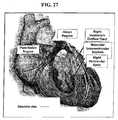
- This conduction system includes the A-V node (heart tissue between the atria and the ventricles that conducts contractile impulses from the atria to the ventricles), the bundle of His and the Purkinje fibers.
- the sinus node creates the synchronized neuraly-mediated signal for cardiac pacing.
- These signals are conducted by the specialized fibers comprising the A-V node and the bundle of His (extending along the length of the septum) and further conducted to the muscle of the heart through the Purkinje fibers.
- the Purkinje fibers originate in the septum and extend through the apex of the heart and to the exterior walls of the heart including into and up the free wall of the left and right ventricles.
- the signal flow from the A-V node to the free wall of the left and right ventricles is rapid to ensure the free wall and septum contract in synchrony.
- a stimulating signal may flow to the free wall in about 70 - 90 milliseconds. In patients with conduction abnormalities, this timing may be significantly delayed (to 150 milliseconds or more) resulting in asynchronous contraction.
- the conduction path through the Purkinje fibers may be blocked.
- the location of the block may be highly localized (as in the case of so-called "left bundle branch block” or LBBB) or may include an enlarged area of dysfunctional tissue (which can result from infarction).
- LBBB left bundle branch block
- all or a portion of the free wall of the left and/or right ventricles is flaccid while the septum is contracting.
- the contraction force of the free wall is weakened.
- CHF patients can be treated with cardiac pacing of the left ventricle.
- cardiac pacing includes applying a stimulus to the septal muscles in synchrony with stimulation applied to the muscles of the free wall of the left ventricle. While infracted tissue will not respond to such stimulus, non-infracted tissue will contract thereby heightening the output of the left ventricle by re-synchronizing the contraction. Accordingly, treatment of CHF is often directed re-synchronization of the myocardium, whereas other ventricular pacing solutions, such as tachycardia and bradycardia, treat heart rate issues.
- the prior art has developed various techniques for accomplishing left ventricle stimulation. For various reasons the techniques may not be ideal. For example, such pacing may result in wide QRS complexes or emboli formation. Thus, endocardial-positioned electrodes in the left ventricle are avoided. However, electrodes can be placed on the epicardial surface of the heart through surgical placement. The epicardial electrodes are positioned on the free wall of the left ventricle and are paced in synchrony with electrodes placed near the septum in the right ventricle.
- epicardial electrodes require a surgical placement, the patient is subjected to two procedures: percutaneous placement of right ventricle electrodes (normally performed in a catheter lab by an electrophysiologist); and surgical placement of epicardial electrodes on the left ventricle (normally placed by a cardiac surgeon in a surgical suite). Such dual procedures are a burden on medical resources.
- Percutaneous procedures have been developed for placement of an electrode to stimulate the free wall of the left ventricle.
- an electrode lead is advanced through the coronary sinus.
- the coronary sinus extends from the right atrium and wraps around the heart on or near the epicardial surface and partially overlies the left ventricle free wall.
- the electrode remains positioned in the coronary sinus overlying the left ventricle free wall with the lead passing through the coronary sinus and through the right atrium to the implantable pulse generator.
- a coronary sinus electrode is frequently less than optimal.
- the portion of the free wall most directly influenced by the electrode is the tissue directly underlying the coronary vein at the location of the electrode. For many patients, this may not be the location of the free wall that benefits the most from a stimulating therapy. Accordingly, the resulting therapy is sub-optimal.
- some patients may have an extremely small-diameter coronary sinus or the coronary sinus may have such a tortuous shape that percutaneous positioning of an electrode within the coronary sinus is impossible or very difficult.
- advancing a lead from the right atrium into the coronary sinus is extremely time-consuming. Even if successful, such a procedure consumes significant health care resources (including precious catheter lab time).
- the present invention is directed to a left ventricle pacing system which does not require epicardial pacing electrodes or pacing electrodes in a coronary sinus or a coronary vein.
- the present invention includes electrodes in the right ventricle near the septal wall. These electrodes create a pulsed electrical field which stimulates both the septum and at least a portion of the free wall of the left and right ventricles. The present invention achieves these objectives without requiring excessive energy demands or power consumption.
- the aspects of the present invention are directed to an apparatus for providing right-ventricle stimulation to re-synchronize a contraction of the musculature of the septum and free wall of the left and right ventricles to create coordinated contraction of the septum and free wall.
- Careful placement of the stimulating electrodes in the right ventricle is used to produce synchronous contractions of the left and right ventricles.
- the right ventricle may be captured along with re-synchronization of the left and right ventricles from a single stimulus point or while maintaining the synchrony of the activation and contraction of the left and right ventricles (in the case that the patient required pacing and did not have an asynchronous contraction without pacing).
- patients that have an asynchronous contraction of the heart can be resynchronized.
- pacing for patients having bradycardia, tachycardia or other rhythm management may be improved by improving upon the asynchronous contraction that often occurs due to the electrical impulse artificially introduced that is not propagating through the normal conduction system of the heart (His-Purkinje system).
- an electrode is carefully placed at the His bundle site ("His Pacing") by screwing in the electrode to get into or beside the bundle itself or by positioning the electrode at a site where the bundle gets to the endocardial surface (denoted supra as EN).
- His Pacing Previous His-pacing efforts (to maintain synchronous contractions that would be otherwise lost due to conventional RV pacing for rate support) have been very burdensome largely because finding this very small region in the right ventricle has been very difficult, and the effort is generally time-consuming, expensive and extremely complex even with modem tools and imaging techniques. Further complicating such procedures is the lack of knowledge regarding the long-term stability of placing a lead in this location.
- Pacing the distal segment of the His bundle has also been shown to remove left bundle block (LBBB) in patients with a proximal lesion of the bundle.
- His pacing is currently contraindicated in patients with a distal lesion of the His bundle or with an intraventricular conduction defect (IVCD), in patients with diffuse peripheral block (at the distal His or diffuse in the Pukinje fibers), and in patients with advanced HF (NYHA class II to IV) and conduction defects.
- IVCD intraventricular conduction defect
- His pacing is used only in a very small subset ( ⁇ 0.01%) of the patients that require ventricular pacing for either Sick Sinus Syndrome, AV block or other Bradyarrhythmia indications by an extremely small group of physicians.
- Xstim waveform a waveform herein referred to as an Xstim waveform, where two pulses of opposite polarity are applied.
- the Xstim waveform generally speaking, is the application of the two pulses of opposite polarity at the same time, or nearly the same time, such that both pulses are associated with the same capture (beat) of the heart.
- the pacing region is located near the location where the His bundle passes close to the endocardial surface of the right ventricle. But in patients with more diffuse block and heart failure, it may move down in the septum towards the apex of the right ventricle. It has also been discovered that careful selection of the waveform may allow for effective pacing using lower voltages, thereby simplifying the design of the output circuits in the pacemaker and the delivery electrodes. It has further been discovered that the desired pacing effect can also be achieved by a single pulse of sufficient amplitude, usually much higher than the amplitude required by the Xstim waveform, and therefore presenting a much higher risk of diaphragmatic and/or phrenic nerve stimulation. It has further been discovered that the amplitude required to achieve the effect is more often lower when that pulse is of anodal nature versus a negative pulse (referenced to the body).
- each electrode may be selectively and independently used to stimulate a synchronous contraction.
- the voltages for each electrode are varied to determine the voltage threshold necessary to produce ventricular capture.
- the voltage threshold can be determined using criteria other than (or in addition to) whether ventricular capture is produced (e.g ., improved heart function).
- Low average stimulation voltage and current may be obtained by selecting the electrode that has the lowest effect threshold (effect refers to resynchronization effect or to maintaining synchrony of the contraction during pacing effect).
- U.S. Patent Nos. 6,230,061 B1 to Hartung issued May 8, 2001 is mentioned here for details of a cardiac pacemaker with localization of the stimulating pulses and U.S. Patent No. 6,907,285 to Denker, et al., dated June 14, 2004 , for details of a wireless defibrillation system; U.S. patent application Publ. No. 2004/0153127 published August 5, 2004 for details related to the use of a microstimulator in the proximity of at least one anatomical structure to produce muscular contractions; U.S. Pat. No. 6,643,546 B2 to Mathis et al. dated November 4, 2003 , for details related to the treatment of congestive heart failure.
- aspects of the present invention are directed to improving heart function as indicated by one or more of several measurable characteristics.
- the discussion and illustrations presented in connection with FIGs. 21-50 provide examples and related results for one or more of these and other aspects of the present invention. These aspects can be implemented in various combinations. To fully appreciate some of these aspects and the related discoveries, the following discussion of FIGs. 1-20 presents related discussion as well as various features that are optional to other embodiments, such as those illustrated and discussed in connection with FIGs. 21-50 .
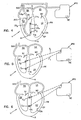
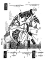
- FIG. 1 illustrates the invention in practice with one such lead.
- the terms “left” and “right” are used herein with reference to the patient's perspective.
- the terms “upper” and “lower” and similar terms such as “up” or “down” are used with reference to the base B of the heart being high and the apex A of the heart H being a lower end.
- FIG. 1 illustrates approaches for pacing of the right and left ventricles from a lead in the right ventricle in a manner consistent with the above discussed aspects.
- heart function can be improved by pacing and/or mapping to delivering such pulses to a cardiac site.
- Such pacing/mapping can also be used to determine a pacing (voltage) threshold, beyond the capture threshold, to improve the heart's function.
- Such an approach can also be used to provide bi-ventricular pacing from a lead in the right ventricle for such improved heart function.
- a patient's heart H is schematically shown in cross-section.
- the heart H includes the upper chambers of the right atrium RA and left atrium LA.
- the lower chambers are the right ventricle RV and left ventricle LV.
- the superior vena cava SVC is shown.
- the mitral valve MV separating the left atrium LA from the left ventricle LV
- the tricuspid valve TV separating the right atrium RA from the right ventricle RV
- the septum S separates the right and left ventricles RV, LV and the free wall FW of the left ventricle LV is separately labeled.
- the surface of the heart wall tissue opposing the chambers is the endocardium and is labeled as EN.
- EN The exterior surface of the heart
- EP The exterior surface of the heart
- coronary vessels of the heart or the pericardium surrounding the heart H are not shown.
- FIG. 1 includes an electrode lead in an embodiment where signals are delivered via a dual (inner and outer) sheath catheter and shown as having a lead body LB 1 and exposed electrodes E 1 and E 2 .
- the first electrode E 1 is positioned near the distal tip of the lead body LB 1 .
- the second electrode E 2 is positioned more proximally on the lead body LB 1 .
- an attachment mechanism AM (such as a passive fixation design with tines or an active fixation design with a metallic helix) is shown for securing the first electrode E 1 to the musculature of the heart H.
- the spacing of electrodes E 1 , E 2 could be greater or smaller than that of convention pacing electrodes permitting positioning of the first electrode E 1 at the apex of the right ventricle RV and the second electrode E 2 in the right ventricle RV near the tricuspid valve TV. It is noted that conventional leads with convention spacing have been used with the first or distal electrode attached to the septum ( e.g ., by a helix attachment HA as shown in FIG. 7A ).
- the position of electrodes E 1 and E 2 is determined by monitoring and analyzing the effectiveness of the pacing.
- an electrocardiogram ECG
- the electrode position may be incrementally adjusted and the feedback from the ECG can be compared for each position.
- the QRS width is used in such a comparison.
- Another parameter that may be considered includes the angle of the vectocardiogram.
- the analysis of the vectocardiogram may be viewed in terms of normalization of the vectocardiogram.
- the efficiency of the contraction can be ascertained by monitoring the synchrony of the contraction using two-dimensional echocardiography.
- the efficiency of the contraction can be ascertained by monitoring the coronary sinus electrogram to determine the time delay that the activation wave front has between the pacing stimuli (or the resulting QRS complex) until a left ventricular activation is detected at the coronary sinus or any other (late activation) structure of the left ventricle. This may be accomplished using an electrophysiology-style catheter or any other catheter with one or more electrodes close to its tip. In one instance, the goal is to minimize the time delay.
- the lead body LB 1 is flexible and includes a bio-compatible, electrically insulating coating surrounding first and second conductors C 1 , C 2 separately connected to the first and second electrodes E 1 , E 2 .
- the lead bodies are broken at a line at the SVC to reveal the internal conductors C 1 , C 2 extending to an implantable pulse generator IPG.
- the conductors C 1 , C 2 are contained within the material of the lead body LB 1 along their length.
- implantable pulse generator IPG is intended to include pacemakers, implantable converter defibrillators (ICD) and cardiac resynchronization therapies (CRT), all known in the art.
- the proximal end of the lead body terminates at a pin connector (not shown) as is customary.
- the pin connector has exposed electrical contacts uniquely connected to each of the conductors C 1 , C 2 .
- the pin connector may be connected to the pulse generator IPG so as to be releasable and with the exposed contacts making electrical connection with unique contacts of the circuitry of the pulse generator IPG.
- the prior art contains numerous examples of cardiac leads for placement in a chamber of the heart where the leads have, as described above, two or more electrodes spaced along a length of the lead, attachment mechanisms such as passive or active fixation and conductors and connector pins as described.
- the current invention is not limited to pacing leads only, but rather is equally deployable with prior art ICD leads where it is customary to contain at least two electrodes in the RV.
- Such leads are selected of biocompatible material and treated (such as sterilized) for chronic placement in the patient.
- the implantable pulse generator IPG is a small metallic container sealed for implantation in the patient and protecting internal circuitry.
- pulse generators are placed subcutaneously (e.g ., in a dissected space between the skin and muscle layers of the patient).
- For cardiac pacing such pulse generators are positioned in the upper chest on either the left or right front side of the patient near a shoulder.
- placement need not be so restricted and such pulse generators could be placed in any convenient location selected by the physician.
- Pulse generators contain internal circuitry for creating electrical impulses which are applied to the electrodes after the lead is connected to the pulse generator. Also, such circuitry may include sensing and amplification circuitry so that electrodes E 1 , E 2 may be used as sensing electrodes to sense and have the IPG report on the patient's electrophysiology.
- the lead may be introduced to the vasculature through a small incision and advanced through the vasculature and into the right atrium RA and right ventricle to the position shown in FIG. 1 .
- Such advancement typically occurs in an electrophysiology lab where the advancement of the lead can be visualized through fluoroscopy.
- the pulse generator contains a battery as a power supply. With subcutaneous placement, replacement of a battery is possible. However, improvements in battery designs have resulted in longer-lasting batteries with the benefit of reducing the frequency of battery replacement. Alternatively, such batteries may be rechargeable in situ.
- the pulse generator circuitry controls the parameters of the signals coupled to the electrodes E 1 , E 2 . These parameters can include pulse amplitude, timing, and pulse duration by way of example.
- the internal circuitry further includes circuit logic permitting reprogramming of the pulse generator to permit a physician to alter pacing parameters to suit the need of a particular patient. Such programming can be affected by inputting programming instructions to the pulse generator via wireless transmission from an external programmer.
- Pulse generators commonly include an exposed contact on the exterior of the generator housing. Such pulse generators may also be partially covered with an insulator, such as silicone, with a window formed in the insulator to expose a portion of the metallic housing which functions as a return electrode in so-called unipolar pacing. In bipolar pacing, the window is not necessary. Most commonly, the electrode is connected by the circuitry of the housing to an electrical ground.
- the pulse generator may be external and coupled to the electrodes by percutaneous leads or wireless transmission.
- a control of an implanted electrode is known for phrenic nerve stimulation and is described more fully in a product brochure, " ATROSTIM PHRENIC NERVE STIMULATOR", AtroTech Oy, P.O. Box 28, FIN-33721, Tampere, Finland (June 2004 ).
- the Atrostim device sends signals from an external controller to an implanted antenna.
- External pacing devices are typically used for providing temporary pacing therapy. Aspects of the current invention are also believed to have advantages for this application as critically-ill patients requiring emergency, temporary pacing may also suffer further from asynchronous cardiac contraction associated with conventional RV pacing. If desired, an external unit can be used to test a patient's suitability for the treatment. Patients who benefit from the therapy can then receive an implantable pulse generator for longer-term use.
- FIG. 2 illustrates a lead body LB 2 in the right ventricle RV with the electrodes E 1 , E 2 directly placed on the septal wall S and held in place against the septal wall through any suitable means.
- FIG. 2A illustrates one embodiment for attachment of an electrode against the septal wall.
- the lead body LB 2 is shown as having an internal lumen LU with a port PO near an electrode ( e.g ., electrode E 2 ).
- Any suitable attachment mechanism (such as a pigtail guide wire or an injected bio-adhesive) can be passed through the lumen LU and port PO to fix the electrode E 2 in abutment against the septal wall S.
- a guide catheter could also be used in moving the implantable lead to assist in the mapping of the optimal location of the septum.
- FIG. 3 illustrates the electrodes E 1 , E 2 against the septal wall S but without requiring an attachment mechanism. Instead, an intermediate region (IR) of the lead body LB 3 is formed of shaped memory material (such as nitinol) to assume an S-shaped configuration and urge the electrodes E 1 , E 2 against the septal wall S.
- shaped memory material such as nitinol
- the lead body LB 4 has two components LB a , LB b joined by an intermediate section IS which may be formed of any elastomeric material (such as a shaped memory material).
- the intermediate section (IS) is biased to urge the two components LB a , LB b into collinear alignment. With the intermediate section IS placed against the apex of the right ventricle (RV), the bias of the intermediate section IS urges the electrodes E 1 , E 2 against the septal wall S.
- FIG. 5 illustrates the electrodes E 1 , E 2 individually placed on the septal wall S and not retained on a lead body.
- the electrodes E 1 , E 2 may be energized in a pacing waveform by wireless transmission signals T 1 , T 2 from the implantable pulse generator (IPG).
- IPG implantable pulse generator
- Wireless transmission from a controller to an electrode is shown in U.S. Patent No. 6,907,285 to Denker, et al., dated June 14, 2004 .
- the electrodes E 1 , E 2 may be directly imbedded as microstimulators into the tissue of the septal wall S as illustrated in FIG. 6 .
- Microstimulators for implantation into human tissue are shown in U.S. patent application Publ. No. 2004/0153127 published August 5, 2004 .
- FIGS. 1-20 illustrate aspects of the present invention similar to that discussed above in connection with FIG. 1 where certain of these figures show common characteristics.
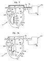
- FIGS. 1 , 7B and 8 illustrate example leads and the associated electrical fields with both electrodes residing within the right ventricle with the distal electrode secured to the apex of the right ventricle, with FIG. 8 showing the ventricles RV, LV and a portion of the lead body LB 1 . While such bipolar leads are acceptable for use with the present invention, a wider spacing between electrodes E 1 , E 2 can increase the field but can sacrifice some sensing capability. This trade-off can be mitigated by use of a three-electrode lead in the right ventricle RV.
- Such a lead would have a tip electrode and two ring electrodes, one located near the tip in the RV apex and one in the high part of the atrium, near the tricuspid valve.
- the sensing is performed between the tip and closer electrode. This will provide good so-called “near field” sensing and avoid so-called “far field” sensing of the atrium or skeletal muscles activity.
- the pacing could be between the ring electrodes to the return electrode located distally to the heart (as will be described).
- One could also combine the tip and nearest ring as one electrode to the return electrode and the other ring electrode to the return electrode at the opposite polarity.
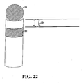
- a ring with a width of 4mm is separated by a distance of 4mm from a tip with a width of 4mm.
- the pulse generator IPG which is common to FIGs. 1-7b .
- the pulse generator IPG generates a first and a second pulsed waveform W 1 , W 2 applied, respectively, to the first and second electrodes E 1 , E 2 .
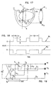
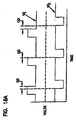
- FIG. 18 shows such waveforms W 1 , W 2 of depicting signals generated by this illustrated IPG.
- the pulse duration (PD) is between about 0.1 to 2.0 milliseconds
- the amplitude A may be 0.1 Volts to 10 or 20 Volts
- the time delay TD between pulses is a targeting heart rate (e.g., 50 to 200 beats per minute).
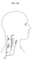
- FIGs. 1-18B show examples of electrode placements (e.g ., electrode E 1 ) at various positions along or near the septal wall.
- electrode E 1 is attached to the mid- or upper-septum.
- the reference electrode RE used in some but not all such embodiments of the present invention, is on the housing of the IPG and positioned subcutaneously near the right or left shoulder.
- the re-direction of the field may also be useful in decreasing defibrillation thresholds for arrangement similar to that shown in FIG. 7B .
- large segmented (for flexibility) electrodes E 2 , E 3 are shown in the superior vena cava SVC near the atrium RA and in the right ventricle to serve as shocking electrodes to defibrillate a patient.
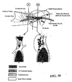
- FIG. 9 shows field lines useful for such stimulation and resulting from movement of the electrodes E 1 , E 2 from the interior of the right ventricle RV ( FIGS. 1 and 8 ) to the septal wall S. Such movement shifts the field lines toward both the septal wall S and the free wall FW of the left ventricle LV.
- reference electrode RE in combination with the electrodes E 1 , E 2 in the right ventricle, provide effective pacing of the left and right ventricles LV.
- the reference electrode RE distorts the electromagnetic field otherwise created between the right ventricle electrodes E 1 , E 2 to urge an intensity of the electromagnetic field deeper into the septal wall S of the left ventricle LV. This may be due to creation of a third high current density spot (or spots) away from the two electrodes in the wall and towards the reference electrode at the point where the current flows between the electrode E 1 and the reference electrode RE and between the electrode E 2 and the reference electrode RE while coinciding in space and time.
- the reference electrode may be physically attached to the housing of the implantable pulse generator IPG (and thereby having a neutral charge). Such an electrode RE is shown in FIGS. 1 - 7B . It will be appreciated that the reference electrode RE can be connected to the implantable pulse generator IPG by a conductor.
- the reference electrode could be another common electrode that exists in the conventional pacing or ICD system, such as an electrode in the atrium or a defibrillation coil electrode situated in the SVC, RA orRV.
- the consequence of the reference electrode RE may have a deforming effect on the electromagnetic field generated between the first and second electrodes E 1 , E 2 .
- This is illustrated in FIG. 10 by distorting the left field lines LFL toward the septal wall S and free wall FW of the left ventricle LV.
- the right field lined (RFL) are compressed toward the axis FA to alter the field from the symmetric presentation of FIGS. 8 and 9 to the asymmetric presentation of FIG. 10 with the field biased toward the septal wall S and the free wall FW of the left ventricle LV.
- Chronic pacing with an anodal electrode is believed to create an exit (anodal) block, meaning that the capture thresholds of the cardiac tissue may go beyond the voltage range of the pulse generator. When this happens the beneficial effect of the stimulation is lost. Since capture is often lost, the patient's life may be placed at risk by such an event.
- the polarity of the charged pulses seen at electrodes E 1 and E 2 may be alternated. This can be particularly useful for avoidance of anodal blocking (gradual rising of the threshold voltage necessary to capture and re-synchronize the myocardium).
- Such polarity swapping may be implemented using a suitable periodicity.
- the polarity of the electrodes is switched after several hours of operation. According to the present invention, this polarity is alternated beat by beat, so that the net charge delivered to the tissue over two beats would be zero.
- the frequency of alternation could be varied in a very wide range and still accomplish the goal of balancing the charge delivered, to allow for the net charge delivered on average to be near zero. This can be useful for avoiding the issue of anodal block and minimizing the risk of electrode dissolution and/or corrosion.
- the optimal lead location can be determined with the assistance of the surface ECG parameters (e.g ., QRS width and/or activation vectors).
- the positioning of the reference electrode RE may be directly on the housing of the implantable pulse generator IPG or may be separate from the internal pulse generator as previously mentioned.
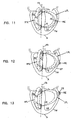
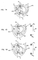
- the reference electrode RE can be placed in the left ventricle ( FIG. 11 ) (or in the tissue of the free wall FW as shown in phantom lines in FIG. 11 ), on the epicardial surface EP ( FIG. 12 ) or in the coronary sinus CS ( FIG. 13 ).
- Positioning the reference electrode RE relative to the heart can affect the distortion of the field in the area of the left ventricle free wall FW subject to pacing. Particularly for a subcutaneously placed reference electrode (which is preferred to minimize the invasive nature of the procedure), the electrical conduction path from the right ventricle RV to the reference electrode will vary considerably between patients.
- the direction of field distortion may alter the region of the left ventricle LV subject to pacing.
- FIG. 15 illustrates the reference electrode RE 1 placed high relative to the heart, resulting in a distortion of the field toward the upper end of the left ventricle septum and free wall FW.
- FIG. 16 illustrates placement of a reference electrode RE 2 lower relative to the heart and to deflect the intensity of the field toward the lower end of the left ventricle septum and free wall FW.
- the reference electrode could be a single electrode, multiple electrodes could be provided for subcutaneous placement and each connected by a switch circuitry SW of the implantable pulse generator as illustrated in FIGS. 15 and 16 .
- the patient's response can be noted with each of the several reference electrodes RE 1 , RE 2 separately connected to the ground or housing of the implantable pulse generator. The patient can then be treated with the electrode showing the most effectiveness for the particular patient. Further, over time, a patient's response may change and the implantable pulse generator can be reprogrammed to select any one of the other reference electrodes as the switched electrode.
- the catheter LB 5 within the right ventricle can have multiple electrodes along its length (as shown in FIG. 7 ). Individual pairs of these electrodes E 1 - E 4 can be switched on or off over time so that the appropriate pair of electrodes within the right ventricle is selected for optimized left ventricular pacing.
- FIG. 14 illustrates how the field can also be distorted by dielectric material DM placed on a side of the electrodes E 1 , E 2 opposite the septal wall S.
- the dielectric material DM result in a distortion of the electrical field biasing the left field lines LFL toward the septal wall S and the free wall FW.
- this configuration will work even better with a reference electrode which will enhance the benefit.
- Various techniques for movement of the electrodes E 1 , E 2 against the septal wall S are disclosed.
- the reference electrode is grounded to the housing of the implantable pulse generator.
- FIG. 17 illustrates an alternative embodiment where the reference electrode includes two active electrodes AE 1 , AE 2 external to the heart.
- the active electrodes AE 1 , AE 2 are paced with pulsed waveforms which are polar opposites of the waveforms on electrodes E 1 , E 2 . This creates dual uni-polar field in addition to the left field lines LFL previously described.
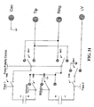
- the amplitude of the waveforms from FIG. 18 is shown in phantom lines as the battery voltage applied to the four poles on the left of FIG. 19 to charge the two pacing capacitors C 1 and C 2 .
- Details of the charging circuitry as well as other controlling circuitry for pacing and sensing are omitted for ease of illustration. In one instance only capacitor C 1 is charged for the pacing output, whereas C 2 is not charged.
- Capacitor C 3 and C 4 are optionally implemented for coupling the pacing output to the patient.
- the output waveform from FIG. 18 with the same amplitude and simultaneous timing is assumed for the design schematic in FIG. 19 .
- a switch S 1 permits selection between unipolar pacing and pacing Xstim or similar pacing (by contact with switch pole A 1 ) or bi-polar pacing (by contact with switch pole A 2 ). Selection between bi-polar pacing or Xstim pacing is made by applying a digital signal with the timing information as shown in FIG. 18 to either T 1 or T 1 and T 2 , namely to either toggle the switch S 5 or S 2 and S 5 simultaneously. An AND gate is used to allow the close of the switch S 2 only for pacing according to Xstim. Switches S 3 and S 4 permit re-neutralization of the pacing charges at the patient-electrode interface.
- the device may be programmable to achieve either conventional bipolar or unipolar stimulation or to achieve the Xstim stimulation through an external programmer or controlled automatically by the device.
- the selection can be based on user preference or be driven by physiological factors such as widths of the patient's QRS complex or the conduction interval between the stimulus to a far away region in the heart.
- switching between the Xstim pacing and other pacing can also be determined by the percentage of pacing with a preference for a higher percentage with the pacing of the present invention.
- the switching from a first type of pacing to the Xstim pacing can be used when there exists an exit block or the pacing electrode is located in infarcted myocardium when first type pacing does not capture (effect the depolarization of) the myocardium at the high output level.
- the automatic determination can be effected through the deployment of any automatic capture detection technology including, but not limited to, electrical sensing of the heart.
- wireless network-enabled switching function for therapy optimization can also be implemented with the present invention. In such cases, certain patient physiologic data are gathered by the implantable device and sent to a remote server/monitor through a wireless communication network.
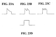
- the stimulus voltage is consistent with discharge of an RC circuit as shown by FIG. 23A . This may be accomplished by connecting the electrode(s) to the anode (and/or cathode) of a charged capacitor.
- the stimulus voltage may be consistent with the discharge of two sets of two capacitors in succession, as shown by FIG. 23B .
- This may be accomplished by connecting the electrode(s) to the anode (and/or cathode) of a first charged capacitor and then to a second charged capacitor.
- This embodiment may be useful for reducing the voltage swing of the pulse, thereby altering the delivery of energy during the active stimulation period and potentially minimizing the voltage required to achieve the desired effect.
- a first set of capacitors could be connected to electrode E 1 and a second set could be connected to electrode E 2 .
- the voltages provided to the electrodes could be of opposite polarity as in the standard Xstim waveform or could be alternated as described above to make the net charge delivered to the electrodes equal to zero.
- FIG. 23C Other embodiments may allow for the use of two sets of three or more capacitors as shown by FIG. 23C .
- various voltage-regulation techniques may be used to provide a constant voltage, or square waveform, as shown by FIG. 23D . This may be useful to provide a more constant delivery of voltage during the active stimulation period. In some instances, such waveforms may allow the reduction of voltage thresholds required to achieve the desired effect.
- one of these groups of three or more capacitors could be connected to electrode E 1 and the other group of three capacitors could be connected to electrode E 2 .
- the two groups may be charged to opposite polarities, as in the standard Xstim waveform.
- the groups may alternate between electrodes E 1 and E 2 , as described above, resulting in the net charge delivered to the stimulus point by the electrodes equal to zero.
- the same effect could be achieved by using an anodal pulse delivered through the capacitive discharge of one, two or three or more capacitors to one of the electrodes with a larger amplitude voltage.
- This anodal pulse will be alternatively connected to one of the stimulating electrodes in one beat and to the next electrode on the next beat.
- the alternating frequency could be lower.
- the anodal capacitive discharge could be alternatively connected to electrode E 1 and then to E 2 every 2 to 10,000 beats. If the alternating charges are equally distributed, the net charge delivered may be kept very close to zero.
- the physician may place an intraventricular pacing lead in a preferred location (locus) that maintains the effect (using one of the previously-described methods, making each electrode alternatively the anode) when either of the electrodes is the anodal electrode.
- the pulse width of the various embodiments may be varied according to the desired treatment and/or in accordance with the response of the particular patient.
- Example pulse widths may range from 0.05 ms to 5.0 ms.
- resynchronization is achieved by presenting a pulsing signal (waveform) to a sweet spot (e.g ., locus in the septal part of the RV endocardium) and, every so often, modulating the signal such as by changing its polarity.
- a pulsing signal waveform
- a sweet spot e.g ., locus in the septal part of the RV endocardium
- modulating the signal such as by changing its polarity.
- the pulsing signal is presented by an electrode and a reference voltage (e.g., a node at the can and/or at the body under treatment)
- the signal can be modulated in a similar manner by adding and/or skipping pulses.
- the power consumption of the pacing device can be an important consideration. While not bounded by theory, it is believed that different pacing profiles can be particularly advantageous to controlling pacing power. For example, during times that the pulses applied to each electrode overlap, the effective voltage seen between the electrodes is believed to be equal to that sum of their amplitudes.
- the pulses shown by the figures are applied to the ring and tip electrodes, such as those illustrated in FIG. 22 .
- the polarity of the voltages, as relative to each other and/or a reference voltage, may be alternated periodically (e.g ., beat by beat or every N pulses). As discussed above, such alternating may be particularly useful for mitigating anodal blocking. Moreover, alternating of pulses may also mitigate corrosion of the electrodes.
- the first electrode E 1 has positively charged pulses only.
- the second electrode E 2 has negatively charged pulses timed to coincide with the positively charged pulses of the positive electrode E 1 .
- direct current (DC) pulses are preferred, the electrodes E 1 , E 2 could be energized with alternating current pulses with the signals to the electrodes E 1 , E 2 out of phase such that the positive pulses on the first electrode E 1 coincide with negative pulses on the second electrode E 2 and negative pulses on the first electrode E 1 coincide with positive pulses on the second electrode E 2 .
- an electrical field is created between the electrodes E 1 , E 2 with a field axis FA ( FIG. 8 ) extending in a line between the electrodes E 1 , E 2 .
- the field is symmetrical about the field axis FA and is represented by field lines illustrated in the drawings as left field lines LFL to the left of the axis FA (with left being from the patient's perspective) and right field lines RFL.
- the field lines represent the intensity of the electrical field. The intensity diminishes rapidly as a function of the distance from the field axis FA.
- a voltage potential across the electrodes is set at a substantially high level.
- high voltages are not practical in a pacing electrode and are more normally associated with defibrillating treatments.
- such voltages may cause phrenic nerve and/or diaphragmatic stimulation and may also cause a significant drain on a battery that would require impractical frequency of battery replacement.
- FIG. 18 illustrates an example waveform with electrodes E 1 , E 2 being simultaneously pulsed with opposite polarity.
- FIG. 18A illustrates waveforms W 1 ', W 2 ' of similar structure to the waveforms of FIG. 18 but out of phase.
- the first set of pulse illustrated in waveforms W 1 ', W 2 ' present a partial overlap duration OD (OD is a positive value).
- the third set of pulses includes pulses that are out of phase such that the leading edge of one pulse occurs after the end of the first pulse of the set (OD has a negative value).
- 18A at least a portion of time includes a monopolar pacing from individual ones of the electrodes E 1 , E 2 to the reference electrode RE. This pacing creates out of phase monopolar fields F 1 , F 2 as illustrated in FIG. 18B .
- Values of OD can range from the entire pulse length ( e.g ., around two milliseconds) to a negative value of several milliseconds ( e.g ., around negative two milliseconds).
- either of the negative or positive pulses can lead the other pulse, respectively.
- the amplitudes of the two waveforms are shown to be equal, they need not be equal in practice nor do they necessary need be implemented as strict square waves.
- the OD can be calculated accordingly.
- the OD may be calculated from beginning or end of the rise/fall of each pulse, respectively.
- the OD may be calculated from when each pulse reaches a certain voltage level, respectively, or once the pulse has maintained a certain voltage level for a period of time.
- FIG. 19 illustrates a representative circuit in schematic format for a portion of a cardiac stimulation pulse generator that is capable of providing pacing output for either the conventional waverforms or Xstim waveforms as herein.
- the circuit of FIG. 19 could be for an implantable pacemaker or any external stimulation system for diagnostic or therapeutic use.
- the stimulation device has three output terminals that are connected to three electrodes E 1 , E 2 , RE in the body. Electrodes E 1 , E 2 are positioned in the right ventricle RV with it being preferred that at least one of these electrodes be in direct contact with the septum S.
- the reference electrode RE is an indifferent electrode which can be connected electronically to the housing of the implantable pulse generator IPG.
- the reference electrode RE may be an electrode directly on the implantable pulse generator or any other electrode for placement inside or outside of the heart as described above.
- the present invention can also be extended to the defibrillation therapy where high-energy pulses with various waveforms are delivered through electrode systems to treat tachycardia and fibrillation (both atrium and ventricle).
- the present invention is believed to be able to achieve a lower defibrillation threshold due to better distribution of the electrical field, causing higher voltage gradient at least in certain parts of the heart compared to that by the conventional defibrillation configuration as seen in FIG. 7B .
- the present invention can be used to perform anti-tachy pacing where faster than conventional pacing pulse sequences are used to stop certain tachyarrhythmia. Aspects consistent with present invention are believed to provide wider coverage of the electrical field and the capability of capturing special conduction systems in the heart (both atrium and ventricle).
- the electrodes E 1 and E 2 are positioned proximate to one another as shown in FIG. 22 .
- This can be particularly useful for localizing the region in which the electrical stimulus (using one of the configurations described before) can achieve the desired synchronization or resynchronization effect.
- the electrodes may have a width of around 4 mm and may be positioned within a distance D of about 5 mm from one another. In another example, the electrodes may be positioned within a distance D of about 2 mm or less.
- the selective placement may be modified for a particular dysfunction and/or for a particular patient.
- the electrodes may be positioned near the His bundle. Locating the electrodes near the His bundle may advantageously allow for capture of both the right and left ventricle. Moreover, resynchronization of the left (or right) ventricle may be possible even for cases of LBBB (or RBBB).
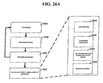
- FIG. 21 shows a system for selectively placing the electrodes.
- the lead discussed in connection with FIG. 22 may be used.
- the lead position is adjusted through various methods via conceptual block 104. If desired, the lead position may be monitored and location information may be provided to myocardium capture analysis block 102.
- Myocardium capture monitor block 106 monitors the effectiveness of the current lead position in capturing and re-synchronizing a contraction of the myocardium of the left and right ventricles. The monitor information is provided to myocardium capture analysis block 102, which processes the received information for the purposes of positioning the electrodes.
- monitor block 106 uses ECG measurements to monitor myocardium capture and re-synchronization.
- Analysis block 102 may analyze various factors of the far field measurements including, but not limited to, the QRS width (e.g ., determined from a vectocardiogram).
- the ECG measurements may be supplied from a number of different inputs including, but not limited to, defibrillation coils, the can of the implantable device, an electrode of a pacing or sensing lead or an external ECG (or similar) device.
- monitor block 106 may measure the amount of blood flow resulting from a contraction of the myocardium.
- the system of FIG. 21 may also be used to adjust other re-synchronization parameters. For instance, the voltage levels and waveforms may be adjusted according to feedback from monitor block 106 and analysis from analysis block 102. In particular it has been discovered that careful placement may allow for low voltages to be applied to the electrodes. In one embodiment, the pacing impedance of the lead and electrodes is low to allow for effective delivery of the pacing voltage. This may be useful for reducing the power consumption of the device and for reducing the voltages necessary to deliver the stimulus. By proceeding in this manner, ( e.g ., using low impedance and maintaining low voltage), phrenic nerve stimulation or diaphragmatic stimulation, both highly undesirable side effects of high pacing, may be avoided.
- the lead has a screw with a short screw relative to screws used to reach the left ventricle or the His bundle. This allows for fixation of the lead until encapsulation and helps reduce mechanical problems associated with such attachments.
- the screw may be made from a non-conductive material, thereby electrically isolating the attachment point.
- the screw may be otherwise electrically isolated from the electrodes for delivering the pacing voltage even where the screw is made from a conductive material.
- a hook is used as the attachment mechanism.
- a T-bar is used as the attachment mechanism.
- the reference electrode may be optionally implemented to provide effective re-synchronization.
- the reference electrode is used to provide a reference voltage derived from the in vivo voltage at a particular location. This reference may be used to reference the voltage provided at the stimulus location to the particular location. For example, the reference location may be taken at the can location or from a reference electrode located near the stimulus location. In another instance, no reference electrode is used.
- selective placement of the electrodes may provide a number of unexpected advantages. More specifically, selective placement of the electrodes along the septum appears to provide re-synchronization of the left and right ventricles even for cases of LBBB where the lesion of the bundle would not be considered proximal. Furthermore, in many instances a large improvement has been seen in the level of synchrony in patients with LBBB and also in patients with moderate or advance HF and conductions defects including LBBB, RBBB and IVCD. For instance, locating the electrodes near an optimal location on the septum has been shown to produce smaller than expected QRS widths. Moreover, the threshold voltages necessary to capture the myocardium of the left and right ventricles or to produce the smaller than expected QRS widths (or indications of improved heart function) may be relatively small.
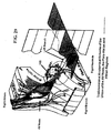
- FIG. 24 shows an example of a sheath for use within the right ventricle 166 of the heart.
- the outer sheath 156 is designed to be inserted through the mitral valve 158 and into ventricle 166.
- Outer sheath 156 may include a J-type bend as shown in the figure. In various applications, this advantageously facilitates the placement of electrodes 160, 164 near the septum and/or the tricuspid valve 162.
- one or more of the outer and an inner sheath 154 may arranged to allow directional control of the sheath position (e.g., by allowing for the adjustment of their curvature).
- inner sheath 154 is located within outer sheath 156. Inner sheath 154 may be adjusted, relative to outer sheath 156, using adjustment mechanism 152. In one instance, the adjustment mechanism 152 includes an adjustable track wheel or another similar mechanism. Additionally, inner sheath 154 may contain a pacing lead and/or a guide wire for additional stability. The adjustment of inner sheath 154 may be accomplished through a number of different techniques. According to one such technique, the inner sheath is allowed freedom to advance through the outer sheath and to move along the septum. In another example technique, the inner sheath may be arranged to direct the lead placement (e.g., by allowing for the adjustment of its curvature).
- the inner sheath and / or the outer sheath may have an electrode at their tip to use for pace mapping the locus for Xstim (following procedures discussed herein), facilitating the insertion of the pacing lead for chronic pacing.
- the inner and out sheaths may be peelable so that the pacemaker lead is kept in place while the sheaths are removed.
- External pacing device 150 provides electrical pulses to the electrodes 160, 164.
- the positioning of the electrodes 160, 164 may be adjusted and the effectiveness of each position may be monitored.
- Various examples of suitable monitoring techniques are discussed in more detail herein.
- the adjustment mechanism includes a number of fixed settings that can be reproduced. This allows for easily retrievable positioning of the electrodes 160, 164 as correlated to the effectiveness of each position.
- the inner sheath may be advanced along positional settings 1 through 10 and corresponding monitoring input may be used to determine which setting is preferred. The inner sheath may then be set to the preferred setting after a comparison between the results corresponding to each of the tested settings.
- each electrode may be selectively and independently used to stimulate a synchronous contraction.
- the voltages for each electrode are varied to determine voltage threshold necessary to produce ventricular capture or to produce improved heart function.
- Low average stimulation voltage and current may be obtained by selecting the electrode that has the lowest effect threshold (effect refers to resynchronization effect or to maintaining synchrony of the contraction during pacing effect).
- the outer and inner sheaths may then be removed.
- a number of techniques may be used for such a removal. Using one such technique a guide wire is advanced through the sheaths and is used to hold the pacing lead in place while the sheaths are removed.
- the sheaths are constructed with a slit that allows for their removal from the pacing lead without significant force being applied to the pacing lead.
- the inner sheath may function as a temporary pacing device connected to an external pacing source.
- the external pacing source may advantageously be equipped with additional processing and display capabilities (relative to an implantable device, which is often limited due to battery life and physical size constraints) to assist in locating the proper placement location.
- the inner and outer sheaths may be removed once the pacing lead is attached.
- the pacing lead may also be connected to an implantable device.
- the external device operates to provide a variety of different voltage waveforms and/or stimulus timings to the stimulus location. Feedback from an ECG or other device may be used to identify the preferred waveforms. The implantable device may then be uploaded with corresponding information for use in providing stimulus.
- the pacemaker may include a wireless port that allows an external interface to monitor and/or adjust the pacing functions. In this manner, the external device need not provide the stimulus through the external sheath. Instead, the implantable device may deliver the same set of stimulus using the wireless interface.
- the outer sheath may be designed with a removable interface that is compatible with both the external pacing device and the implantable pacing device. This allows for the use of the external pacing device during placement of the electrode(s) and use of the same outer sheath with the implantable pacing. This may be particularly useful for reducing the size of the sheath, the cost of the device or for simplifying the procedure by avoiding the step of removing the outer sheath.
- FIGS. 24A-D depict additional waveform patterns that may be provided by an electronic circuit.
- FIG. 24A shows pulses A1, A2 and A5, which represent voltages applied to a first electrode (e.g ., the voltage differential between the tip and the can), while pulses A3 and A4 represent voltages applied to a second electrode (e.g ., the voltage differential between the ring and the can).
- Control logic in the pacemaker device allows for the individual adjustment of the voltage amplitude of the various pulses and for the adjustment of the pulse width or duration.
- the specific parameters may be implemented by iteratively changing the waveforms and monitoring the effectiveness of the pulse.
- the selection of the ideal waveform may be made by selecting the waveform that produces the smallest QRS width as measured by an ECG. While FIG. 24A depicts the pulse polarity as alternating each beat, it should be apparent from the discussion herein and from FIGS. 24B-C that this is merely one example of a possible pulse modulation scheme.
- one or more pulses may be withheld as shown by the lack of a pulse on the ring electrode that corresponds to pulse A5 on the tip. In this sense the ring electrode pulse has effectively been withheld or skipped. In certain embodiments, either or both of the pulses may be withheld. Such withholding of pulses may be periodically implemented ( e.g ., once per every N pulses, or once every 20 minutes per 24 hours to allow heart to be conditioned by its own intrinsic contraction if the intrinsic heart rate is above a certain acceptable rate, such as 50 beats/minute). In another instance, the withholding may be responsive to feedback from a sensing electrode or ECG input.
- an example procedure for determining placement of a lead for pacing involves at least one repetition of pacing, sensing and repositioning using at least one lead adapted to deliver a pacing profile. While, not all of the data shown in the various figures was implemented as part of the experimental tests discussed herein, it is believed that the data shown is accurate.
- pacing of the heart is accomplished using a lead placed in the right ventricle and near the His bundle. The lead includes two electrodes to deliver oppositely charged pulses. Heart functionality associated with the pacing then is monitored.
- the monitoring can include one or more of the following examples, ECG readings (e.g ., QRS width or fractionation), electrical activity of a late activation site in the left ventricle, mechanical contraction of the heart or measurement of the blood flow (e.g., the rate of change in pressure).
- ECG readings e.g ., QRS width or fractionation
- electrical activity of a late activation site in the left ventricle e.g., the rate of change in pressure
- the lead is repositioned and pacing and monitoring can be repeated.
- pacing can be implemented in various ways. For instance, DDD (dual chamber) pacing can be implemented with or without a low atrial rate (e.g ., around 50 beats per minute) and an AV delay of around one-half of the baseline or intrinsic AV interval.
- the DDD pacing can also be modified to use a variety of different Xstim pacing profiles, non-Xstim pacing profiles and combinations thereof.
- a way to assess improved heart function involves determining placement of a lead for sensing a late activation site in the left ventricle.
- the lead which is capable of sensing electrical activity in nearby heart tissue, is advanced through the CS (coronary sinus) until monitoring results from the lead represent activation of a late activating region.
- the lead can be continuously advanced until activation of a distal electrode on the lead no longer occurs before any other electrode(s) on the lead. At this point, the current lead position can either be maintained or the lead can be slightly retracted.
- experimental data provides strong support that the beneficial effects on cardiac function provided by aspects of the present invention are due, at least in part, to His bundle stimulation.
- the data further supports that, unexpectedly, the His bundle may react more like a nerve than a myocyte with respect to responsiveness to electrical stimulation. This may be due in part to fibrotic encapsulation of the His bundle.
- Xstim pacing can be attributed in part to the phenomena of anodal break stimulation in tissues with high directional anisotropy. It is also possible the success of Xstim pacing can be attributed in part to a phenomenon sometimes referred to as accommodation. Accommodation is an increase in voltage threshold necessary to produce depolarization of a nerve cell that occurs when the nerve is exposed to a non-zero voltage that is below the threshold voltage.
- FIG. 25A shows a pacing approach for a pacing device implemented in connection with an example embodiment.
- An input is received at block 201 and used at block 203 to determine a condition of conduction abnormality using.
- QRS morphology recognition features e.g ., QRS width, fractionation or late activation timing
- QRS width, fractionation or late activation timing are used to automatically determine whether a patient's ventricular conduction system is normal or abnormal.
- an inhibit mode is carried out at block 205 to inhibit ventricular pacing.
- This inhibition is similar, for example, to inhibition as implemented with right-sided CRM (cardiac rhythm management) devices.
- intrinsic activation e.g ., electrical pulse that is not generated by a ventricular pacing electrode
- CRM pacing may be inhibited in response to the detection of an intrinsic activation.
- the device operates in a ventricular pacing preference (VPP) mode per block 207.
- VPP ventricular pacing preference
- the VPP mode an AV delay is shortened in a dual chamber device in patients with normal atrial activity.
- the pacing rate is increased in the VPP mode to promote ventricular pacing. This is particularly beneficial for patients who have less than ideal intrinsic activation of one or more ventricles (e.g ., due to LBB, RBB, wide QRS and other conduction abnormalities).
- careful placement of the stimulating electrode and/or use of Xstim or similar pacing signals may be used to provide the VPP mode.
- the determination of step 203 may include a comparison of ventricular contractions due to the VPP mode to contractions due to intrinsic activation (e.g., by comparing QRS width).
- received input (201) can be provided to a chronic pacing device, such as an implantable pacemaker.
- a chronic pacing device such as an implantable pacemaker.
- an implantable device could include sensing capabilities for assessing ventricular function and conduction abnormalities. The implantable device would inhibit (not provide) ventricular pacing signals so long as the assessment was favorable; however, ventricular pacing could be started should the assessment indicate conduction abnormalities.
- Such a device could be implemented, for example, where the implantable device is providing functionality other than compensating for conduction abnormalities (e.g., providing defibrillation therapy or treating tachycardia or bradycardia).
- Another possibility involves periodic assessments of the patient and treatment.
- the assessment and selection of whether to inhibit or pace could be made at set intervals of time or even responsive to external stimulus, such as could be provided by a heath professional.
- an external pacing system can be useful in assessing whether or not to inhibit pacing.
- aspects of the present invention relate to an external pacing system that can be useful for implementing a chronic pacing device according to embodiments of the present invention.
- Such an external pacing system can contain pacing output circuitry which is selectively controlled to generate Xstim or other pacing waveforms.
- the pacing locations are located near the His bundle and the pacing profile is an Xstim profile.
- this circuitry is used to generate a modulated pacing waveform for multiple pacing objectives.
- One implementation of the system can includes a surface ECG module and/or connectors to receive ECG signal inputs from other ECG machines.
- Aspects of the invention are also directed to a user interface display that shows data showing changes in heart function parameters associated with pacing waveforms and/or lead placement.
- the display may also show the ECG signals from at least one lead or data from other sensors configured to monitor heart function.
- the heart function can be assessed using a number of different parameters. These parameters can be useful for providing an indication that the pacing is being delivered to the proper location and/or with the proper pacing profile. Thus, aspects of the present invention can be particularly useful for assessing a pacing location/profile using data in addition to whether a capture has been successful. This can allow for assessing heart function between multiple pacing locations, each of which resulted in capture of the left and right ventricles.
- one implementation involves an automatic heart function (e.g ., QRS width, late activation timing, fractionation and/or pressure) detection/assessment algorithm that is built into the system.
- QRS width e.g ., in milliseconds
- the detection algorithm can determine the QRS width (e.g ., in milliseconds).
- the QRS width can either be displayed numerically, or be transformed into various color diodes, beeping tones, or beeping intervals, to allow direct visual or audio feedback to a user of the system.
- a similar feedback mechanism can be implemented for various other heart function indicia (e.g ., maximum/minimum rate of pressure change or late activation timing).
- FIG. 25B shows a system 200 that can be used to determine placement and pacing parameters.
- System 200 can be used in connection with the flow diagram of FIG. 25A .
- This figure shows ECG input (206) and vectocardiogram input (204), however, the invention is not so limited and can use a variety inputs for different heart function measurements.
- Pacing signals are provided (202) to implanted electrodes 216 (which can also include an implantable pulse generator IPG) to pace at a location in the right ventricle. During efforts to determine the pacing location, pacing signals can be provided from an external source. Alternatively, the pacing signals can be provided by an implanted IPG 216.
- the pacing signals can optionally be controlled and/or modified from users settings 214 or other user input.
- user setting 214 may include one or more pacing profiles that can be implemented as the pacing leads 216 are moved between different locations.
- IPG 216 can store one or more pacing profiles to deliver to the heart. IPG 216 can autonomously generate pacing signals or IPG 216 can be prompted by external control signals to implement one of the pacing profiles.
- Monitoring device(s) 212 such as an electrocardiogram (ECG) and/or a vetocardiogram, are used to monitor various pacing parameters. Data from monitoring device(s) 212 is provided to various inputs 204, 206 of the system 200. Processor 210 evaluates the input from the monitoring device 212, and feedback can be provided via display 208.
- An example of a suitable display includes simplistic feedback that is easily understood by a doctor that would otherwise be involved in placing the electrodes, such as color coded LEDs (e.g., red, yellow and green), effectiveness ratings (e.g., 1-10 rating based on QRS morphology), or audio signals. Additional information may be provided in the form of graphical display of the electrical waveform or other data from various monitoring devices (e.g., a surface ECG, an endocardiogram or a vectocardiogram).
- a user of the system may adjust settings of the pacing through user setting interface 214. For example, the user may incrementally lower the pacing voltage to determine the optimal or minimum threshold voltage.
- aspects of the present invention are directed to use of a pacing threshold set based upon heart function separate from or in addition to the capture threshold voltage. This can result in a threshold being set significantly higher than the capture threshold.
- the system may also contain amplifiers and related signal processors programmed to automatically determine expected intervals and correlate them to detected time intervals from the various endocardiograms or combinations of surface QRS to endocardiograms.
- This information can be analyzed using one or more processors 210.
- detected time intervals can be used provide indicators, as mentioned above, useful in determining the desired pacing site. The results of such an analysis can then be used to determine the best parameters for treatment of the patient.
- a variety of pacing waveforms can be monitored and assessed including conventional pacing and Xstim pacing.
- One or more pacing waveforms can then be selected. The selection can be used to configure IPG 216 for chronic pacing.
- the system 200 can be particularly useful for implementing methods of lead placement and/or profile selection. A few examples of such methods are discussed below in connection with FIGs. 26A , 26B , 26C and 26D .
- FIG. 26A shows an example procedure for determining placement of a lead for pacing according to an embodiment of the present invention. This procedure was implemented to place the pacing lead in connection with the experimental results provided hereafter.
- pacing of the heart is accomplished using a lead placed in the right ventricle and near the His bundle.
- the lead includes two electrodes used to deliver oppositely charged pulses, such as with Xstim pacing.
- heart functionality associated with the pacing is monitored.
- the monitoring can include one or more of the following non-limiting examples, ECG readings (e.g. , QRS width or fractionation), electrical activity of a late activation site in the left ventricle, mechanical contraction of the heart or measurement of the blood flow (e.g., the maximum rate of change in left ventricular pressure).
- the improved heart function can be based upon a comparison of heart function without any pacing.
- pacing uses relatively high voltages (e.g ., +/- 5V) when pacing to determine lead location. This can be useful to ensure that the improved heart function is seen.
- pacing capture can sometimes still be obtained without exhibiting significant improvement in heart function.
- the improved heart function can sometimes be an improvement over heart function resulting from use of the pacing lead and pacing profile rather than (or in addition to) the baseline and/or unpaced heart function.
- the lead is repositioned and pacing and monitoring steps 4526 and 4528 can be repeated as desired.
- the results of the monitoring step can be saved and correlated to the corresponding lead positions.
- the results of the monitoring step 4528 are used to determine the proper placement for the lead.
- a few examples of the results of the monitoring step are shown by 4534 (QRS narrowing), 4536 (fractionation improvement), 4538 (late activation site earlier) and 4540 (mechanical function improved).
- the lead can then be moved (back) to the lead position that is selected as a function of the monitoring results.
- the steps 4530 and 4532 can be switched so that repositioning of the lead is done after evaluating the results of the monitoring step 4528. In this manner, the lead can be repositioned until satisfactory results are detected. This can be particularly useful for not having to record and recreate lead positions previously paced. Instead, once satisfactory monitor results are found, the current lead placement can be used.
- FIG. 26B shows an example procedure for determining placement of a lead for pacing according to an embodiment of the present invention.
- baseline heart function is recorded (e.g ., without Xstim pacing).
- a lead capable of delivering Xstim pacing is placed near the His bundle ( i.e., near the root of the septal leaflet of the tricuspid valve in the right ventricle).
- Xstim pacing is delivered to the placed lead.
- the Xstim pacing is consistent with the waveforms depicted by and discussed in connection with FIG. 18 .
- the heart function associated with the Xstim pacing is recorded.
- step 4510 If it is determined, at step 4510, that Xstim pacing improves heart function (e.g ., narrowing of the QRS, less fractionated QRS, improving timing of a late activation site, improved mechanical function or improved pressure function), the placement of the lead can be selected (and fixed) at step 4512. Otherwise, the position of the placed lead can be adjusted at step 4514 and steps 4506-4510 can be repeated as necessary.
- Xstim pacing improves heart function
- the determination step 4510 can implemented using multi-lead ECG readings and a probe placed at a late activation site of the left ventricle (e.g ., placing a lead near the posterior lateral wall of the left ventricle via a catheter inserted through the Coronary Sinus).
- DDD pacing can be implemented as shown in step 4516.
- the DDD pacing is implemented with a low atrial rate (e.g ., around 50 beats per minute) and an AV delay of around one-half of the baseline or intrinsic AV interval (to allow for full capture and atrial tracking and ventricular pacing).
- the DDD pacing is modified to use a variety of different Xstim pacing profiles as shown in step 4518.
- one or more of these profiles can be selected from the following non-limiting examples (discussed in terms of a lead with tip and ring electrodes for simplicity), in-phase pulses with positive voltage applied to the tip and negative voltage applied to the ring, in-phase pulses with negative voltage applied to the tip and positive voltage applied to the ring, out-of-phase pulses with opposite polarities applied to respective tip and ring electrodes.
- the pacing profile can be adjusted in step 4524.
- pocket stimulation effects, dry pocket or other effects due to chronic stimulation can result in the threshold voltage increasing.
- shifting the overlap duration of the pulses (OD) can help compensate for such problems.
- the OD can be shifted to allow for lower pacing voltages, even where no dry pocket or other causes are present.
- FIG. 26C shows an example procedure for determining placement of a lead for sensing a late activation site in the left ventricle, according to an embodiment of the present invention.
- the monitoring of a late activation site of the left ventricle can be useful for placement of pacing lead(s) and/or assessment of pacing effectiveness.
- the method involves the use of a lead that is capable of sensing electrical activity in nearby heart tissue.
- the lead is advanced through the coronary sinus until monitoring results from the lead represent activation of a late activating region.
- the lead can be advanced to a desired spatial position within the coronary sinus.
- the lead placement can be determined using a number of different mechanisms, such as fluoroscopy or physical measurements of distance of lead advancements.
- Each patient may exhibit different morphology and/or electrical conduction/activation. Patients who have conduction abnormalities may exhibit late activation at sites different from patients with normal conduction.
- the method depicted by FIG. 26C uses electrical measurements taken from the advancing lead to determine the desired sensing position.
- Step 4542 shows that the lead includes multiple sensing electrodes. These sensing electrodes are spatially disparate along the length of the lead. In this manner the most distal electrode represents the electrode that has been advanced the furthest. The remaining electrodes follow.
- FIG. 26D a simplified version of an example lead is shown by lead 4500. The distal sensing electrode 4550 is followed by sensing electrodes 4552, 4554 and 4556.
- step 4544 a determination is made at step 4544 as to the relationship between the activation times sensed at the sensing electrodes.
- the lead can be advanced further as shown by step 4546.
- the lead can be continuously advanced until activation of distal electrode 4550 no longer occurs before all of the other electrodes.
- the current lead position can either be maintained or the lead can be slightly retracted, as shown by step 4548.
- the lead can be advanced a significant distance into the coronary sinus and a particular sensor can be selected (e.g., by selecting a sensor that shows a late activation relative to the other sensors).
- the absolute amplitude of the voltage presented to one of the electrodes can be less than the absolute amplitude of the voltage presented to the other electrode.
- This 'unbalanced' pacing profile may provide adequate pacing, while helping to control pacing power.
- the power consumption of the pacing device can be an important consideration. While not bounded by theory, it is believed that different pacing profiles can be particularly advantageous to controlling pacing power. For example, during times that the pulses applied to each electrode overlap, the effective voltage seen between the electrodes is believed to be equal to that sum of their amplitudes. During times that the pulses do not overlap, the effective voltage is believed to be about equal to the amplitude of the active electrode. Assuming the voltages of the opposite polarity pulses have equal absolute magnitudes (A), the instantaneous power draw for overlapping pulses is proportional to 4A 2 . The instantaneous power draw for non-overlapping pulses is proportional to A 2 .
- the power drawn is then proportional to 4TA 2 .
- the power drawn is proportional to 2TA 2 . While it has been observed that non-overlapping pacing profiles may exhibit pacing thresholds that are around 0.5 volts higher than those of overlapping pacing profiles, power savings are still believed to be possible using non-overlapping pulses in place of overlapping pulses.
- FIG. 27 shows a cross-sectional view of a heart and the Hisian and para-Hisian regions.
- FIG. 27 is a view of the right side of the heart, with the Hisian and para-Hisian pacing areas shown by the dotted lines. These regions represent the general area in which the pacing sites for the experimental data were collected.
- FIG. 28 shows a cross-sectional view of the heart marked with pacing sites, according to an example embodiment of the present invention. Representative waveforms for different pacing areas are shown along the sides of the figure.
- the top left waveform represents a pacing site for a single patient and shows significant atrial (A), Hisian and ventricular (V) signals.
- the middle left waveform represents a pacing site for 13 patients and shows minor atrial signals with relatively strong Hisian and ventricular signals.
- the bottom left waveform represents a single patient and shows relatively strong atrial and ventricular signals with little Hisian signal.
- the right two waveforms represent a single patient and two patients, respectively, each with primarily only a ventricular signal.
- FIG. 29 shows the location of pacing sites on a three-dimensional depiction of the union of the AV node, the para-Hisian and Hisian regions.
- FIG. 30 shows the location of pacing sites on several cross-sectional views of the heart.
- the upper view is a sectional view that includes part of the conduction system that includes the AV node, the His bundle and the right bundle branch.
- the lower two views show respective perpendicular views taken at respective portions of the conduction system of the upper view.
- FIG. 31 shows an example circuit for providing various stimulation profiles, according to an example embodiment of the present invention.
- Switches 5002 and 5008 are enabled to produce a pacing event.
- Switches 5004, 5006, 5010, 5012 and 5014 are set to provide a variety of pacing profiles.
- Switches 5004, 5006 and 5014 provide the ability to switch between bi-ventricular pacing and single-ventricle pacing ( e.g ., Xstim).
- Switches 5010 and 5012 provide the ability to modify the polarity of the pulses applied to the various electrodes.
- switches 5004, 5006 and 5014 are set for Xstim pacing.
- Switches 5004 and 5014 are connected to the ground (e.g ., to the can or reference electrode).
- Switch 5006 is connected to switch 5012.
- both positive and negative voltages are delivered to the ring and tip electrodes as determined by switches 5010 and 5012.
- the electrodes need not be so limited. For instance, while the tip electrode is closer to the distal end of the lead, the tip electrode need not be located on the distal tip.
- the ring electrode could be something other than ring as various other electrode configurations are possible.
- switches 5104, 5106 and 5114 are set for bi-ventricular pacing.
- Switch 5104 is connected to switch 5112.
- Switch 5106 is connected to ground.
- Switch 5114 is connected the left ventricle lead. In this manner, pacing can be delivered to leads located at both ventricles.
- a three output channel arrangement to facilitate a BiV pacing profile where the LV is paced with a conventional negative pulse and RV paced with Xstim.
- Switches 5110 and 5112 provide the ability to modify the polarity of the voltages seen between the ring and tip electrodes of the right ventricle pacing lead.
- the pacing profile can include, for example, variations in voltage levels, pulse durations and phase differences between pulses.
- pacing profiles allow for a number of different applications to be implemented.
- the results of pacing e.g ., QRS width, pressure measurements, synchronicity of contracts and the like
- results can then be used to select the pacing profile (e.g ., Xstim or bi-ventricular) that is to be used for the patient.
- the device in another application, includes a sensing function to detect the function of the left ventricle.
- the sensed function can be used to determine whether the current pacing profile is adequate and/or capturing a contraction of the left ventricle.
- Xstim pacing is used while sensing heart function in the left ventricle.
- the pacing profile can be adjusted accordingly. Adjustment of the pacing profile can involve adjustment of the voltage. For instance, when partial or complete lack of capture is detected, the pacing voltage could be increased.
- Other example variations include a change in the polarity of the ring and tip electrodes or an adjustment of the phase of the applied voltages.
- the device when inadequate left ventricular function is detected, the device can be changed to a bi-ventricular pacing profile. In some instances, the device can periodically attempt to implement an Xstim pacing profile. If, during the attempt, adequate left ventricular function is detected, Xstim pacing can be resumed. Otherwise, biventricular pacing can continue to be implemented.
- the device senses atrium function.
- This sensed function can be used, for example, to determine the timing for the ventricular pacing profile.
- the atrium function can be sensed using an electrode in the atrium, or using sensing near the His bundle (e.g ., the Xstim pacing lead).
- the sensed function can be detected using the ring lead, the tip lead and/or a dedicated sensing electrode.
- the lead includes a sensing electrode that is closer to the distal end of the lead than the ring and tip electrodes. Generally speaking, such placement would allow the sensing electrode to be located such that the sensed atrium signal would be expected to be stronger ( e.g ., due to placement closer to the atrium).
- Cardiac applications represent a specific embodiment of the invention; however, the present invention is also applicable to other therapies, such as those where high current density spot(s) away from the electrodes are beneficial for stimulating the target including, but not limited to, nerves, muscle, gastric and intestine system, and cortex.
- therapies such as those where high current density spot(s) away from the electrodes are beneficial for stimulating the target including, but not limited to, nerves, muscle, gastric and intestine system, and cortex.
- U.S. Pat. No. 5,299,569 to Wernicke et al. issued April 5, 1994 is one of a number of patents assigned to Cyberonics, Inc. describing pacing the vagus nerve to treat a wide variety of disorders.
- Pacing electrodes are applied directly to the vagus nerve in, for example, the neck.
- Application of an electrode directly to the vagus nerve creates risk of mechanical injury (e.g ., pressure necrosis) to the nerve.
- FIG. 20 illustrates use of the present invention in such application.
- Electrodes E 1 , E 2 are placed subcutaneously near (transcutaneously or transvenously coupled) but not on the vagus nerve (VN) in the neck.
- a reference electrode RE is placed subcutaneously (transcutaneously or transvenously coupled) on an opposite side of the nerve VN.
- the electrodes E 1 , E 2 and RE are connected to a pulse generator IPG. With signals as described above, the resulting field F captures the vagus nerve.
- the signals may be selected to have amplitude, frequency and other parameters as more fully described in the '569 patent. It will be appreciated that other alternative examples of using the present invention to pace an organ or the nerve will occur to one of ordinary skill in the art with the benefit of the teachings of the present invention.
Claims (6)
- Système configuré pour une utilisation en connexion avec une stimulation ventriculaire d'un ventricule gauche d'un coeur en provenance d'une connexion de stimulation située dans le ventricule droit, le système comprenant :un capteur configuré pour détecter une fonction ventriculaire du coeur ;un agencement de traitement configuré pour évaluer la fonction ventriculaire détectée afin de déterminer si oui ou non une anomalie de conduction existe ;un circuit de stimulation configuré pour appliquer deux impulsions de stimulation de polarités opposées au moins partiellement concurrentes (A1-A5) sur au moins deux électrodes (E1-E4) situées au niveau d'un septum de ventricule droit au niveau ou à proximité d'un faisceau de His, en réponse à la détermination du fait qu'une anomalie de conduction existe et afin d'inhiber les impulsions de stimulation de polarités opposées en réponse à la détermination du fait que l'anomalie de conduction n'existe pas, caractérisé en ce que les polarités des impulsions de stimulation délivrées sur les au moins deux électrodes sont alternées battement à battement.
- Système selon la revendication 1, dans lequel le système est agencé de manière à pouvoir être implanté.
- Système selon la revendication 1, dans lequel l'évaluation inclut le fait de déclarer que l'anomalie de conduction existe lorsqu'une largeur de QRS mesurée excède une valeur de seuil d'au moins 120 millisecondes.
- Système selon la revendication 1, dans lequel le capteur est configuré pour fournir des données utilisées pour déterminer la largeur de QRS.
- Système selon la revendication 1, dans lequel le capteur est configuré pour fournir des données utilisées pour déterminer un cadencement entre une activation d'un site d'activation tardif du ventricule gauche et une partie d'un complexe QRS.
- Système selon la revendication 1, dans lequel le capteur est configuré pour fournir des données utilisées pour déterminer un taux maximum de variation de pression tel que vu dans le ventricule gauche.
Applications Claiming Priority (5)
| Application Number | Priority Date | Filing Date | Title |
|---|---|---|---|
| US94730807P | 2007-06-29 | 2007-06-29 | |
| US94734207P | 2007-06-29 | 2007-06-29 | |
| US12/147,369 US8010192B2 (en) | 2004-12-20 | 2008-06-26 | Endocardial pacing relating to conduction abnormalities |
| US12/147,293 US8014861B2 (en) | 2004-12-20 | 2008-06-26 | Systems, devices and methods relating to endocardial pacing for resynchronization |
| PCT/US2008/068654 WO2009006339A1 (fr) | 2007-06-29 | 2008-06-27 | Stimulation endocardiaque en relation avec des anomalies de conduction |
Publications (3)
| Publication Number | Publication Date |
|---|---|
| EP2164562A1 EP2164562A1 (fr) | 2010-03-24 |
| EP2164562A4 EP2164562A4 (fr) | 2010-10-20 |
| EP2164562B1 true EP2164562B1 (fr) | 2014-10-01 |
Family
ID=40226501
Family Applications (1)
| Application Number | Title | Priority Date | Filing Date |
|---|---|---|---|
| EP08796045.6A Not-in-force EP2164562B1 (fr) | 2007-06-29 | 2008-06-27 | Stimulation endocardiaque en relation avec des anomalies de conduction |
Country Status (4)
| Country | Link |
|---|---|
| EP (1) | EP2164562B1 (fr) |
| JP (2) | JP2010532231A (fr) |
| AU (1) | AU2008269934A1 (fr) |
| WO (1) | WO2009006339A1 (fr) |
Cited By (1)
| Publication number | Priority date | Publication date | Assignee | Title |
|---|---|---|---|---|
| WO2023144635A1 (fr) * | 2022-01-26 | 2023-08-03 | Medtronic, Inc. | Dispositif médical et procédé de stimulation cardiaque du système de conduction de his-purkinje |
Families Citing this family (15)
| Publication number | Priority date | Publication date | Assignee | Title |
|---|---|---|---|---|
| US8005544B2 (en) | 2004-12-20 | 2011-08-23 | Cardiac Pacemakers, Inc. | Endocardial pacing devices and methods useful for resynchronization and defibrillation |
| AR047851A1 (es) | 2004-12-20 | 2006-03-01 | Giniger Alberto German | Un nuevo marcapasos que restablece o preserva la conduccion electrica fisiologica del corazon y un metodo de aplicacion |
| US8010192B2 (en) | 2004-12-20 | 2011-08-30 | Cardiac Pacemakers, Inc. | Endocardial pacing relating to conduction abnormalities |
| US8014861B2 (en) | 2004-12-20 | 2011-09-06 | Cardiac Pacemakers, Inc. | Systems, devices and methods relating to endocardial pacing for resynchronization |
| US8290586B2 (en) | 2004-12-20 | 2012-10-16 | Cardiac Pacemakers, Inc. | Methods, devices and systems for single-chamber pacing using a dual-chamber pacing device |
| US8326423B2 (en) | 2004-12-20 | 2012-12-04 | Cardiac Pacemakers, Inc. | Devices and methods for steering electrical stimulation in cardiac rhythm management |
| US8010191B2 (en) | 2004-12-20 | 2011-08-30 | Cardiac Pacemakers, Inc. | Systems, devices and methods for monitoring efficiency of pacing |
| US8423139B2 (en) | 2004-12-20 | 2013-04-16 | Cardiac Pacemakers, Inc. | Methods, devices and systems for cardiac rhythm management using an electrode arrangement |
| US8050756B2 (en) | 2004-12-20 | 2011-11-01 | Cardiac Pacemakers, Inc. | Circuit-based devices and methods for pulse control of endocardial pacing in cardiac rhythm management |
| US8688217B2 (en) | 2008-10-24 | 2014-04-01 | Boston Scientific Neuromodulation Corporation | Method to detect proper lead connection in an implantable stimulation system |
| US8260424B2 (en) | 2008-10-24 | 2012-09-04 | Boston Scientific Neuromodulation Corporation | Systems and methods for detecting a loss of electrical connectivity between components of implantable medical lead systems |
| US8688234B2 (en) | 2008-12-19 | 2014-04-01 | Cardiac Pacemakers, Inc. | Devices, methods, and systems including cardiac pacing |
| US8401639B2 (en) * | 2009-04-13 | 2013-03-19 | Cardiac Pacemakers, Inc. | Anodal stimulation detection and avoidance |
| US8565880B2 (en) | 2010-04-27 | 2013-10-22 | Cardiac Pacemakers, Inc. | His-bundle capture verification and monitoring |
| WO2012125273A2 (fr) | 2011-03-14 | 2012-09-20 | Cardiac Pacemakers, Inc. | Vérification de capture de his à l'aide de retard électro-mécanique |
Family Cites Families (15)
| Publication number | Priority date | Publication date | Assignee | Title |
|---|---|---|---|---|
| US5174289A (en) * | 1990-09-07 | 1992-12-29 | Cohen Fred M | Pacing systems and methods for control of the ventricular activation sequence |
| SE9304029D0 (sv) * | 1993-12-03 | 1993-12-03 | Siemens Elema Ab | Analysanordning för att analysera elektriska signaler från ett hjärta |
| US6096064A (en) * | 1997-09-19 | 2000-08-01 | Intermedics Inc. | Four chamber pacer for dilated cardiomyopthy |
| US6144880A (en) | 1998-05-08 | 2000-11-07 | Cardiac Pacemakers, Inc. | Cardiac pacing using adjustable atrio-ventricular delays |
| CA2331316A1 (fr) * | 1998-05-08 | 1999-11-18 | Andrew P. Kramer | Stimulation cardiaque utilisant des retards auriculo-ventriculaires reglables |
| US20050203580A1 (en) * | 2001-02-13 | 2005-09-15 | Prentice John K. | Method for multiple site, right ventricular pacing with improved left ventricular function |
| WO2002087501A2 (fr) | 2001-04-27 | 2002-11-07 | Quetzal Biomedical, Inc. | Fils ameliores pour le traitement de patients atteints d'insuffisance cardiaque congestive |
| US6871096B2 (en) * | 2001-10-26 | 2005-03-22 | Medtronic, Inc. | System and method for bi-ventricular fusion pacing |
| US7065405B2 (en) * | 2002-11-15 | 2006-06-20 | Cardiac Pacemakers, Inc. | Stress reduction pacing mode for arrhythmia prevention |
| US7558626B2 (en) * | 2003-04-23 | 2009-07-07 | Medtronic, Inc. | Cardiac resynchronization via left ventricular pacing |
| US9002452B2 (en) * | 2003-11-07 | 2015-04-07 | Cardiac Pacemakers, Inc. | Electrical therapy for diastolic dysfunction |
| EP1703944B1 (fr) * | 2003-12-19 | 2015-07-08 | Cardiac Pacemakers, Inc. | Ajustement de parametres de stimulation biventriculaire sequentielle |
| AR047851A1 (es) * | 2004-12-20 | 2006-03-01 | Giniger Alberto German | Un nuevo marcapasos que restablece o preserva la conduccion electrica fisiologica del corazon y un metodo de aplicacion |
| US7702392B2 (en) * | 2005-09-12 | 2010-04-20 | Ebr Systems, Inc. | Methods and apparatus for determining cardiac stimulation sites using hemodynamic data |
| EP2276400A2 (fr) * | 2008-05-13 | 2011-01-26 | Proteus Biomedical, Inc. | Systèmes de tomographie à champ continu et leurs procédés d'utilisation |
-
2008
- 2008-06-27 JP JP2010515198A patent/JP2010532231A/ja active Pending
- 2008-06-27 EP EP08796045.6A patent/EP2164562B1/fr not_active Not-in-force
- 2008-06-27 AU AU2008269934A patent/AU2008269934A1/en not_active Abandoned
- 2008-06-27 WO PCT/US2008/068654 patent/WO2009006339A1/fr active Application Filing
-
2014
- 2014-03-19 JP JP2014056437A patent/JP5819460B2/ja not_active Expired - Fee Related
Cited By (1)
| Publication number | Priority date | Publication date | Assignee | Title |
|---|---|---|---|---|
| WO2023144635A1 (fr) * | 2022-01-26 | 2023-08-03 | Medtronic, Inc. | Dispositif médical et procédé de stimulation cardiaque du système de conduction de his-purkinje |
Also Published As
| Publication number | Publication date |
|---|---|
| WO2009006339A1 (fr) | 2009-01-08 |
| EP2164562A1 (fr) | 2010-03-24 |
| JP2014138884A (ja) | 2014-07-31 |
| AU2008269934A1 (en) | 2009-01-08 |
| EP2164562A4 (fr) | 2010-10-20 |
| JP2010532231A (ja) | 2010-10-07 |
| JP5819460B2 (ja) | 2015-11-24 |
Similar Documents
| Publication | Publication Date | Title |
|---|---|---|
| US8934969B2 (en) | Systems, devices and methods for monitoring efficiency of pacing | |
| US8880169B2 (en) | Endocardial pacing relating to conduction abnormalities | |
| US9031648B2 (en) | Endocardial pacing devices and methods useful for resynchronization and defibrillation | |
| US8812105B2 (en) | Circuit-based devices and methods for pulse control of endocardial pacing in cardiac rhythm management | |
| US9008768B2 (en) | Methods, devices and systems for cardiac rhythm management using an electrode arrangement | |
| US8014861B2 (en) | Systems, devices and methods relating to endocardial pacing for resynchronization | |
| US8825159B2 (en) | Devices and methods for steering electrical stimulation in cardiac rhythm management | |
| EP2164560B1 (fr) | Systèmes pour la gestion du rythme cardiaque au moyen d'un ensemble électrode | |
| EP2164562B1 (fr) | Stimulation endocardiaque en relation avec des anomalies de conduction | |
| WO2009006331A1 (fr) | Dispositifs de stimulation électrique endocardiaque et méthodes utilisées pour la resynchronisation et la défibrillation | |
| WO2009006327A1 (fr) | Systèmes, dispositifs et procédés pour suivre l'efficacité de la stimulation cardiaque | |
| WO2009006325A1 (fr) | Dispositifs et méthodes pour guider la stimulation électrique dans la gestion du rythme cardiaque | |
| WO2009006329A1 (fr) | Dispositifs et procédés à base de circuits pour la régulation des impulsions de stimulation endocardiaque appliquée à la gestion du rythme cardiaque |
Legal Events
| Date | Code | Title | Description |
|---|---|---|---|
| PUAI | Public reference made under article 153(3) epc to a published international application that has entered the european phase |
Free format text: ORIGINAL CODE: 0009012 |
|
| 17P | Request for examination filed |
Effective date: 20100127 |
|
| AK | Designated contracting states |
Kind code of ref document: A1 Designated state(s): AT BE BG CH CY CZ DE DK EE ES FI FR GB GR HR HU IE IS IT LI LT LU LV MC MT NL NO PL PT RO SE SI SK TR |
|
| AX | Request for extension of the european patent |
Extension state: AL BA MK RS |
|
| DAX | Request for extension of the european patent (deleted) | ||
| A4 | Supplementary search report drawn up and despatched |
Effective date: 20100921 |
|
| RAP1 | Party data changed (applicant data changed or rights of an application transferred) |
Owner name: CARDIAC PACEMAKERS, INC. |
|
| 17Q | First examination report despatched |
Effective date: 20120104 |
|
| REG | Reference to a national code |
Ref country code: DE Ref legal event code: R079 Ref document number: 602008034689 Country of ref document: DE Free format text: PREVIOUS MAIN CLASS: A61N0001000000 Ipc: A61N0001362000 |
|
| RIC1 | Information provided on ipc code assigned before grant |
Ipc: A61N 1/362 20060101AFI20140306BHEP Ipc: A61N 1/368 20060101ALI20140306BHEP Ipc: A61N 1/365 20060101ALI20140306BHEP |
|
| GRAP | Despatch of communication of intention to grant a patent |
Free format text: ORIGINAL CODE: EPIDOSNIGR1 |
|
| INTG | Intention to grant announced |
Effective date: 20140411 |
|
| GRAS | Grant fee paid |
Free format text: ORIGINAL CODE: EPIDOSNIGR3 |
|
| GRAA | (expected) grant |
Free format text: ORIGINAL CODE: 0009210 |
|
| AK | Designated contracting states |
Kind code of ref document: B1 Designated state(s): AT BE BG CH CY CZ DE DK EE ES FI FR GB GR HR HU IE IS IT LI LT LU LV MC MT NL NO PL PT RO SE SI SK TR |
|
| REG | Reference to a national code |
Ref country code: GB Ref legal event code: FG4D |
|
| REG | Reference to a national code |
Ref country code: CH Ref legal event code: EP Ref country code: AT Ref legal event code: REF Ref document number: 689205 Country of ref document: AT Kind code of ref document: T Effective date: 20141015 |
|
| REG | Reference to a national code |
Ref country code: IE Ref legal event code: FG4D |
|
| REG | Reference to a national code |
Ref country code: DE Ref legal event code: R096 Ref document number: 602008034689 Country of ref document: DE Effective date: 20141113 |
|
| REG | Reference to a national code |
Ref country code: NL Ref legal event code: VDEP Effective date: 20141001 |
|
| REG | Reference to a national code |
Ref country code: AT Ref legal event code: MK05 Ref document number: 689205 Country of ref document: AT Kind code of ref document: T Effective date: 20141001 |
|
| REG | Reference to a national code |
Ref country code: LT Ref legal event code: MG4D |
|
| PG25 | Lapsed in a contracting state [announced via postgrant information from national office to epo] |
Ref country code: NL Free format text: LAPSE BECAUSE OF FAILURE TO SUBMIT A TRANSLATION OF THE DESCRIPTION OR TO PAY THE FEE WITHIN THE PRESCRIBED TIME-LIMIT Effective date: 20141001 |
|
| PG25 | Lapsed in a contracting state [announced via postgrant information from national office to epo] |
Ref country code: PT Free format text: LAPSE BECAUSE OF FAILURE TO SUBMIT A TRANSLATION OF THE DESCRIPTION OR TO PAY THE FEE WITHIN THE PRESCRIBED TIME-LIMIT Effective date: 20150202 Ref country code: LT Free format text: LAPSE BECAUSE OF FAILURE TO SUBMIT A TRANSLATION OF THE DESCRIPTION OR TO PAY THE FEE WITHIN THE PRESCRIBED TIME-LIMIT Effective date: 20141001 Ref country code: CZ Free format text: LAPSE BECAUSE OF FAILURE TO SUBMIT A TRANSLATION OF THE DESCRIPTION OR TO PAY THE FEE WITHIN THE PRESCRIBED TIME-LIMIT Effective date: 20141001 Ref country code: NO Free format text: LAPSE BECAUSE OF FAILURE TO SUBMIT A TRANSLATION OF THE DESCRIPTION OR TO PAY THE FEE WITHIN THE PRESCRIBED TIME-LIMIT Effective date: 20150101 Ref country code: FI Free format text: LAPSE BECAUSE OF FAILURE TO SUBMIT A TRANSLATION OF THE DESCRIPTION OR TO PAY THE FEE WITHIN THE PRESCRIBED TIME-LIMIT Effective date: 20141001 Ref country code: ES Free format text: LAPSE BECAUSE OF FAILURE TO SUBMIT A TRANSLATION OF THE DESCRIPTION OR TO PAY THE FEE WITHIN THE PRESCRIBED TIME-LIMIT Effective date: 20141001 Ref country code: IS Free format text: LAPSE BECAUSE OF FAILURE TO SUBMIT A TRANSLATION OF THE DESCRIPTION OR TO PAY THE FEE WITHIN THE PRESCRIBED TIME-LIMIT Effective date: 20150201 |
|
| PG25 | Lapsed in a contracting state [announced via postgrant information from national office to epo] |
Ref country code: AT Free format text: LAPSE BECAUSE OF FAILURE TO SUBMIT A TRANSLATION OF THE DESCRIPTION OR TO PAY THE FEE WITHIN THE PRESCRIBED TIME-LIMIT Effective date: 20141001 Ref country code: HR Free format text: LAPSE BECAUSE OF FAILURE TO SUBMIT A TRANSLATION OF THE DESCRIPTION OR TO PAY THE FEE WITHIN THE PRESCRIBED TIME-LIMIT Effective date: 20141001 Ref country code: LV Free format text: LAPSE BECAUSE OF FAILURE TO SUBMIT A TRANSLATION OF THE DESCRIPTION OR TO PAY THE FEE WITHIN THE PRESCRIBED TIME-LIMIT Effective date: 20141001 Ref country code: GR Free format text: LAPSE BECAUSE OF FAILURE TO SUBMIT A TRANSLATION OF THE DESCRIPTION OR TO PAY THE FEE WITHIN THE PRESCRIBED TIME-LIMIT Effective date: 20150102 Ref country code: SE Free format text: LAPSE BECAUSE OF FAILURE TO SUBMIT A TRANSLATION OF THE DESCRIPTION OR TO PAY THE FEE WITHIN THE PRESCRIBED TIME-LIMIT Effective date: 20141001 Ref country code: PL Free format text: LAPSE BECAUSE OF FAILURE TO SUBMIT A TRANSLATION OF THE DESCRIPTION OR TO PAY THE FEE WITHIN THE PRESCRIBED TIME-LIMIT Effective date: 20141001 Ref country code: CY Free format text: LAPSE BECAUSE OF FAILURE TO SUBMIT A TRANSLATION OF THE DESCRIPTION OR TO PAY THE FEE WITHIN THE PRESCRIBED TIME-LIMIT Effective date: 20141001 |
|
| REG | Reference to a national code |
Ref country code: DE Ref legal event code: R097 Ref document number: 602008034689 Country of ref document: DE |
|
| PG25 | Lapsed in a contracting state [announced via postgrant information from national office to epo] |
Ref country code: DK Free format text: LAPSE BECAUSE OF FAILURE TO SUBMIT A TRANSLATION OF THE DESCRIPTION OR TO PAY THE FEE WITHIN THE PRESCRIBED TIME-LIMIT Effective date: 20141001 Ref country code: SK Free format text: LAPSE BECAUSE OF FAILURE TO SUBMIT A TRANSLATION OF THE DESCRIPTION OR TO PAY THE FEE WITHIN THE PRESCRIBED TIME-LIMIT Effective date: 20141001 Ref country code: EE Free format text: LAPSE BECAUSE OF FAILURE TO SUBMIT A TRANSLATION OF THE DESCRIPTION OR TO PAY THE FEE WITHIN THE PRESCRIBED TIME-LIMIT Effective date: 20141001 Ref country code: RO Free format text: LAPSE BECAUSE OF FAILURE TO SUBMIT A TRANSLATION OF THE DESCRIPTION OR TO PAY THE FEE WITHIN THE PRESCRIBED TIME-LIMIT Effective date: 20141001 |
|
| PLBE | No opposition filed within time limit |
Free format text: ORIGINAL CODE: 0009261 |
|
| STAA | Information on the status of an ep patent application or granted ep patent |
Free format text: STATUS: NO OPPOSITION FILED WITHIN TIME LIMIT |
|
| 26N | No opposition filed |
Effective date: 20150702 |
|
| REG | Reference to a national code |
Ref country code: DE Ref legal event code: R082 Ref document number: 602008034689 Country of ref document: DE Representative=s name: PFENNING, MEINIG & PARTNER MBB PATENTANWAELTE, DE |
|
| PG25 | Lapsed in a contracting state [announced via postgrant information from national office to epo] |
Ref country code: MC Free format text: LAPSE BECAUSE OF FAILURE TO SUBMIT A TRANSLATION OF THE DESCRIPTION OR TO PAY THE FEE WITHIN THE PRESCRIBED TIME-LIMIT Effective date: 20141001 |
|
| REG | Reference to a national code |
Ref country code: CH Ref legal event code: PL |
|
| GBPC | Gb: european patent ceased through non-payment of renewal fee |
Effective date: 20150627 |
|
| PG25 | Lapsed in a contracting state [announced via postgrant information from national office to epo] |
Ref country code: LU Free format text: LAPSE BECAUSE OF FAILURE TO SUBMIT A TRANSLATION OF THE DESCRIPTION OR TO PAY THE FEE WITHIN THE PRESCRIBED TIME-LIMIT Effective date: 20150627 Ref country code: SI Free format text: LAPSE BECAUSE OF FAILURE TO SUBMIT A TRANSLATION OF THE DESCRIPTION OR TO PAY THE FEE WITHIN THE PRESCRIBED TIME-LIMIT Effective date: 20141001 |
|
| REG | Reference to a national code |
Ref country code: IE Ref legal event code: MM4A |
|
| REG | Reference to a national code |
Ref country code: FR Ref legal event code: ST Effective date: 20160229 |
|
| PG25 | Lapsed in a contracting state [announced via postgrant information from national office to epo] |
Ref country code: LI Free format text: LAPSE BECAUSE OF NON-PAYMENT OF DUE FEES Effective date: 20150630 Ref country code: CH Free format text: LAPSE BECAUSE OF NON-PAYMENT OF DUE FEES Effective date: 20150630 Ref country code: IE Free format text: LAPSE BECAUSE OF NON-PAYMENT OF DUE FEES Effective date: 20150627 Ref country code: GB Free format text: LAPSE BECAUSE OF NON-PAYMENT OF DUE FEES Effective date: 20150627 |
|
| PG25 | Lapsed in a contracting state [announced via postgrant information from national office to epo] |
Ref country code: FR Free format text: LAPSE BECAUSE OF NON-PAYMENT OF DUE FEES Effective date: 20150630 |
|
| PGFP | Annual fee paid to national office [announced via postgrant information from national office to epo] |
Ref country code: IT Payment date: 20160621 Year of fee payment: 9 |
|
| PG25 | Lapsed in a contracting state [announced via postgrant information from national office to epo] |
Ref country code: MT Free format text: LAPSE BECAUSE OF FAILURE TO SUBMIT A TRANSLATION OF THE DESCRIPTION OR TO PAY THE FEE WITHIN THE PRESCRIBED TIME-LIMIT Effective date: 20141001 |
|
| PG25 | Lapsed in a contracting state [announced via postgrant information from national office to epo] |
Ref country code: BG Free format text: LAPSE BECAUSE OF FAILURE TO SUBMIT A TRANSLATION OF THE DESCRIPTION OR TO PAY THE FEE WITHIN THE PRESCRIBED TIME-LIMIT Effective date: 20141001 Ref country code: HU Free format text: LAPSE BECAUSE OF FAILURE TO SUBMIT A TRANSLATION OF THE DESCRIPTION OR TO PAY THE FEE WITHIN THE PRESCRIBED TIME-LIMIT; INVALID AB INITIO Effective date: 20080627 |
|
| PG25 | Lapsed in a contracting state [announced via postgrant information from national office to epo] |
Ref country code: TR Free format text: LAPSE BECAUSE OF FAILURE TO SUBMIT A TRANSLATION OF THE DESCRIPTION OR TO PAY THE FEE WITHIN THE PRESCRIBED TIME-LIMIT Effective date: 20141001 |
|
| PG25 | Lapsed in a contracting state [announced via postgrant information from national office to epo] |
Ref country code: BE Free format text: LAPSE BECAUSE OF FAILURE TO SUBMIT A TRANSLATION OF THE DESCRIPTION OR TO PAY THE FEE WITHIN THE PRESCRIBED TIME-LIMIT Effective date: 20141001 |
|
| PG25 | Lapsed in a contracting state [announced via postgrant information from national office to epo] |
Ref country code: IT Free format text: LAPSE BECAUSE OF NON-PAYMENT OF DUE FEES Effective date: 20170627 |
|
| PGFP | Annual fee paid to national office [announced via postgrant information from national office to epo] |
Ref country code: DE Payment date: 20180629 Year of fee payment: 11 |
|
| REG | Reference to a national code |
Ref country code: DE Ref legal event code: R119 Ref document number: 602008034689 Country of ref document: DE |
|
| PG25 | Lapsed in a contracting state [announced via postgrant information from national office to epo] |
Ref country code: DE Free format text: LAPSE BECAUSE OF NON-PAYMENT OF DUE FEES Effective date: 20200101 |