EP2164062A1 - Display device - Google Patents
Display device Download PDFInfo
- Publication number
- EP2164062A1 EP2164062A1 EP08752861A EP08752861A EP2164062A1 EP 2164062 A1 EP2164062 A1 EP 2164062A1 EP 08752861 A EP08752861 A EP 08752861A EP 08752861 A EP08752861 A EP 08752861A EP 2164062 A1 EP2164062 A1 EP 2164062A1
- Authority
- EP
- European Patent Office
- Prior art keywords
- display
- dimming
- clock time
- brightness
- data
- Prior art date
- Legal status (The legal status is an assumption and is not a legal conclusion. Google has not performed a legal analysis and makes no representation as to the accuracy of the status listed.)
- Withdrawn
Links
Images

Classifications
-
- G—PHYSICS
- G09—EDUCATION; CRYPTOGRAPHY; DISPLAY; ADVERTISING; SEALS
- G09G—ARRANGEMENTS OR CIRCUITS FOR CONTROL OF INDICATING DEVICES USING STATIC MEANS TO PRESENT VARIABLE INFORMATION
- G09G3/00—Control arrangements or circuits, of interest only in connection with visual indicators other than cathode-ray tubes
- G09G3/20—Control arrangements or circuits, of interest only in connection with visual indicators other than cathode-ray tubes for presentation of an assembly of a number of characters, e.g. a page, by composing the assembly by combination of individual elements arranged in a matrix no fixed position being assigned to or needed to be assigned to the individual characters or partial characters
- G09G3/34—Control arrangements or circuits, of interest only in connection with visual indicators other than cathode-ray tubes for presentation of an assembly of a number of characters, e.g. a page, by composing the assembly by combination of individual elements arranged in a matrix no fixed position being assigned to or needed to be assigned to the individual characters or partial characters by control of light from an independent source
- G09G3/3406—Control of illumination source
-
- G—PHYSICS
- G09—EDUCATION; CRYPTOGRAPHY; DISPLAY; ADVERTISING; SEALS
- G09G—ARRANGEMENTS OR CIRCUITS FOR CONTROL OF INDICATING DEVICES USING STATIC MEANS TO PRESENT VARIABLE INFORMATION
- G09G3/00—Control arrangements or circuits, of interest only in connection with visual indicators other than cathode-ray tubes
- G09G3/20—Control arrangements or circuits, of interest only in connection with visual indicators other than cathode-ray tubes for presentation of an assembly of a number of characters, e.g. a page, by composing the assembly by combination of individual elements arranged in a matrix no fixed position being assigned to or needed to be assigned to the individual characters or partial characters
- G09G3/34—Control arrangements or circuits, of interest only in connection with visual indicators other than cathode-ray tubes for presentation of an assembly of a number of characters, e.g. a page, by composing the assembly by combination of individual elements arranged in a matrix no fixed position being assigned to or needed to be assigned to the individual characters or partial characters by control of light from an independent source
- G09G3/36—Control arrangements or circuits, of interest only in connection with visual indicators other than cathode-ray tubes for presentation of an assembly of a number of characters, e.g. a page, by composing the assembly by combination of individual elements arranged in a matrix no fixed position being assigned to or needed to be assigned to the individual characters or partial characters by control of light from an independent source using liquid crystals
-
- G—PHYSICS
- G02—OPTICS
- G02F—OPTICAL DEVICES OR ARRANGEMENTS FOR THE CONTROL OF LIGHT BY MODIFICATION OF THE OPTICAL PROPERTIES OF THE MEDIA OF THE ELEMENTS INVOLVED THEREIN; NON-LINEAR OPTICS; FREQUENCY-CHANGING OF LIGHT; OPTICAL LOGIC ELEMENTS; OPTICAL ANALOGUE/DIGITAL CONVERTERS
- G02F1/00—Devices or arrangements for the control of the intensity, colour, phase, polarisation or direction of light arriving from an independent light source, e.g. switching, gating or modulating; Non-linear optics
- G02F1/01—Devices or arrangements for the control of the intensity, colour, phase, polarisation or direction of light arriving from an independent light source, e.g. switching, gating or modulating; Non-linear optics for the control of the intensity, phase, polarisation or colour
- G02F1/13—Devices or arrangements for the control of the intensity, colour, phase, polarisation or direction of light arriving from an independent light source, e.g. switching, gating or modulating; Non-linear optics for the control of the intensity, phase, polarisation or colour based on liquid crystals, e.g. single liquid crystal display cells
- G02F1/133—Constructional arrangements; Operation of liquid crystal cells; Circuit arrangements
-
- G—PHYSICS
- G09—EDUCATION; CRYPTOGRAPHY; DISPLAY; ADVERTISING; SEALS
- G09G—ARRANGEMENTS OR CIRCUITS FOR CONTROL OF INDICATING DEVICES USING STATIC MEANS TO PRESENT VARIABLE INFORMATION
- G09G3/00—Control arrangements or circuits, of interest only in connection with visual indicators other than cathode-ray tubes
- G09G3/20—Control arrangements or circuits, of interest only in connection with visual indicators other than cathode-ray tubes for presentation of an assembly of a number of characters, e.g. a page, by composing the assembly by combination of individual elements arranged in a matrix no fixed position being assigned to or needed to be assigned to the individual characters or partial characters
-
- G—PHYSICS
- G09—EDUCATION; CRYPTOGRAPHY; DISPLAY; ADVERTISING; SEALS
- G09G—ARRANGEMENTS OR CIRCUITS FOR CONTROL OF INDICATING DEVICES USING STATIC MEANS TO PRESENT VARIABLE INFORMATION
- G09G3/00—Control arrangements or circuits, of interest only in connection with visual indicators other than cathode-ray tubes
- G09G3/20—Control arrangements or circuits, of interest only in connection with visual indicators other than cathode-ray tubes for presentation of an assembly of a number of characters, e.g. a page, by composing the assembly by combination of individual elements arranged in a matrix no fixed position being assigned to or needed to be assigned to the individual characters or partial characters
- G09G3/22—Control arrangements or circuits, of interest only in connection with visual indicators other than cathode-ray tubes for presentation of an assembly of a number of characters, e.g. a page, by composing the assembly by combination of individual elements arranged in a matrix no fixed position being assigned to or needed to be assigned to the individual characters or partial characters using controlled light sources
- G09G3/30—Control arrangements or circuits, of interest only in connection with visual indicators other than cathode-ray tubes for presentation of an assembly of a number of characters, e.g. a page, by composing the assembly by combination of individual elements arranged in a matrix no fixed position being assigned to or needed to be assigned to the individual characters or partial characters using controlled light sources using electroluminescent panels
- G09G3/32—Control arrangements or circuits, of interest only in connection with visual indicators other than cathode-ray tubes for presentation of an assembly of a number of characters, e.g. a page, by composing the assembly by combination of individual elements arranged in a matrix no fixed position being assigned to or needed to be assigned to the individual characters or partial characters using controlled light sources using electroluminescent panels semiconductive, e.g. using light-emitting diodes [LED]
-
- G—PHYSICS
- G02—OPTICS
- G02F—OPTICAL DEVICES OR ARRANGEMENTS FOR THE CONTROL OF LIGHT BY MODIFICATION OF THE OPTICAL PROPERTIES OF THE MEDIA OF THE ELEMENTS INVOLVED THEREIN; NON-LINEAR OPTICS; FREQUENCY-CHANGING OF LIGHT; OPTICAL LOGIC ELEMENTS; OPTICAL ANALOGUE/DIGITAL CONVERTERS
- G02F1/00—Devices or arrangements for the control of the intensity, colour, phase, polarisation or direction of light arriving from an independent light source, e.g. switching, gating or modulating; Non-linear optics
- G02F1/01—Devices or arrangements for the control of the intensity, colour, phase, polarisation or direction of light arriving from an independent light source, e.g. switching, gating or modulating; Non-linear optics for the control of the intensity, phase, polarisation or colour
- G02F1/13—Devices or arrangements for the control of the intensity, colour, phase, polarisation or direction of light arriving from an independent light source, e.g. switching, gating or modulating; Non-linear optics for the control of the intensity, phase, polarisation or colour based on liquid crystals, e.g. single liquid crystal display cells
- G02F1/133—Constructional arrangements; Operation of liquid crystal cells; Circuit arrangements
- G02F1/1333—Constructional arrangements; Manufacturing methods
- G02F1/1335—Structural association of cells with optical devices, e.g. polarisers or reflectors
- G02F1/1336—Illuminating devices
- G02F1/133601—Illuminating devices for spatial active dimming
-
- G—PHYSICS
- G02—OPTICS
- G02F—OPTICAL DEVICES OR ARRANGEMENTS FOR THE CONTROL OF LIGHT BY MODIFICATION OF THE OPTICAL PROPERTIES OF THE MEDIA OF THE ELEMENTS INVOLVED THEREIN; NON-LINEAR OPTICS; FREQUENCY-CHANGING OF LIGHT; OPTICAL LOGIC ELEMENTS; OPTICAL ANALOGUE/DIGITAL CONVERTERS
- G02F1/00—Devices or arrangements for the control of the intensity, colour, phase, polarisation or direction of light arriving from an independent light source, e.g. switching, gating or modulating; Non-linear optics
- G02F1/01—Devices or arrangements for the control of the intensity, colour, phase, polarisation or direction of light arriving from an independent light source, e.g. switching, gating or modulating; Non-linear optics for the control of the intensity, phase, polarisation or colour
- G02F1/13—Devices or arrangements for the control of the intensity, colour, phase, polarisation or direction of light arriving from an independent light source, e.g. switching, gating or modulating; Non-linear optics for the control of the intensity, phase, polarisation or colour based on liquid crystals, e.g. single liquid crystal display cells
- G02F1/133—Constructional arrangements; Operation of liquid crystal cells; Circuit arrangements
- G02F1/1333—Constructional arrangements; Manufacturing methods
- G02F1/1335—Structural association of cells with optical devices, e.g. polarisers or reflectors
- G02F1/1336—Illuminating devices
- G02F1/133602—Direct backlight
- G02F1/133612—Electrical details
-
- G—PHYSICS
- G09—EDUCATION; CRYPTOGRAPHY; DISPLAY; ADVERTISING; SEALS
- G09G—ARRANGEMENTS OR CIRCUITS FOR CONTROL OF INDICATING DEVICES USING STATIC MEANS TO PRESENT VARIABLE INFORMATION
- G09G2310/00—Command of the display device
- G09G2310/08—Details of timing specific for flat panels, other than clock recovery
-
- G—PHYSICS
- G09—EDUCATION; CRYPTOGRAPHY; DISPLAY; ADVERTISING; SEALS
- G09G—ARRANGEMENTS OR CIRCUITS FOR CONTROL OF INDICATING DEVICES USING STATIC MEANS TO PRESENT VARIABLE INFORMATION
- G09G2320/00—Control of display operating conditions
- G09G2320/06—Adjustment of display parameters
- G09G2320/0606—Manual adjustment
-
- G—PHYSICS
- G09—EDUCATION; CRYPTOGRAPHY; DISPLAY; ADVERTISING; SEALS
- G09G—ARRANGEMENTS OR CIRCUITS FOR CONTROL OF INDICATING DEVICES USING STATIC MEANS TO PRESENT VARIABLE INFORMATION
- G09G2320/00—Control of display operating conditions
- G09G2320/06—Adjustment of display parameters
- G09G2320/0626—Adjustment of display parameters for control of overall brightness
- G09G2320/0633—Adjustment of display parameters for control of overall brightness by amplitude modulation of the brightness of the illumination source
-
- G—PHYSICS
- G09—EDUCATION; CRYPTOGRAPHY; DISPLAY; ADVERTISING; SEALS
- G09G—ARRANGEMENTS OR CIRCUITS FOR CONTROL OF INDICATING DEVICES USING STATIC MEANS TO PRESENT VARIABLE INFORMATION
- G09G2320/00—Control of display operating conditions
- G09G2320/06—Adjustment of display parameters
- G09G2320/0626—Adjustment of display parameters for control of overall brightness
- G09G2320/0653—Controlling or limiting the speed of brightness adjustment of the illumination source
Definitions
- the present invention relates to a display device to be used in, for example, various kinds of vehicles and particularly to a display device in which brightness of display means can be changed.
- the display device includes display means made of a liquid crystal panel, control means formed of a microcomputer that causes the display means to display predetermined display information and updates the display information at a predetermined timing, illumination means formed of a backlight for illuminating the display means, and dimming means that changes brightness of the illumination means.
- the control means changes the brightness of the illumination means on the basis of input information from the dimming means.
- an image drawing process for displaying predetermined display information on display means needs a certain time period for processing.
- an update cycle for example, 100 ms may be necessary for the display information.
- a problem arises when the dimming means is operated in response to ambient brightness, change of brightness made by the illumination means is ahead of the display information, so that a user may feel discomfort.
- using of a microcomputer having a high performance is considerable.
- the cost may increase due to the use of the microcomputer.
- the present invention provides a display device capable of eliminating feeling of discomfort of a user while preventing the cost from increasing.
- a display device includes display means, control means that causes the display means to display predetermined display information and updates the display information at a predetermined timing, illumination means that illuminates the display means or another display means disposed at a periphery of the display means, and dimming means that changes brightness of the illumination means.
- the control means chooses the brightness of the illumination means on the basis of input information from the dimming means and changes the brightness of the illumination means at a timing in response to the timing for updating the display information.
- the control means performs first processing for determining a dimming level by the dimming means and second processing for making output of controlling the brightness of the illumination means to be coincident with the timing at a time after a predetermined time period has elapsed from the first processing on the basis of the dimming level determined by the first processing.
- the initial purpose can be achieved, and it is possible to provide the display device capable of eliminating feeling of discomfort of a user while preventing the cost from being increased.
- Figs. 1 and 2 are schematic views showing an embodiment of the invention.
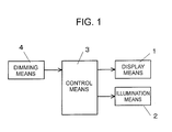
- Fig. 1 is a block diagram showing a system structure of a display device according to the invention
- Fig. 2 is a timing diagram showing operations of the embodiment.
- the display device is built in a meter apparatus installed in, for example, a vehicle, and displays traveling information such as a travel distance, a vehicle speed, navigation, traffic information or the like, or vehicle information indicative of warning or notice of a state of each section of the vehicle.
- the display device includes display means 1, illumination means 2, control means 3 and dimming means 4.
- the display means 1 can be formed of a flat display panel constituted by, for example, a dot matrix type liquid crystal panel.
- the illumination means 2 can be formed of a surface light source device constituted by a light source having, for example, a plurality of light emitting diodes and a light guide for guiding the light from the light source to the display means 1.
- the control means 3 can be formed of a microcomputer and is connected to various devices of the vehicle via CAN (Controller Area Network) communication cables or wires (not shown).
- the control means 3 receives an input signal relating to the travel information or the vehicle information (hereinafter, entirely referred to as display information), causes the display means 1 to display the display information in accordance with the input signal, and updates the display information at a predetermined timing (an update cycle). Further, the control means 3 receives a dimming signal relating to dimming information from the dimming means and controls the brightness of the illumination means 2.
- control means 3 includes a CPU for performing arithmetic processing on the basis of various information, a storage section having a readable, rewritable RAM for temporarily storing results of the arithmetic processing or the like by the CPU and a ROM storing a control program or control data, and an input/output interface that is connected to a bus so as to communicate the various information, a control signal, a clock signal or a latch signal.
- the dimming means 4 can be formed of, for example, a rotary encoder or a potentiometer. When a user carries out a rotational operation of a knob (not shown), the dimming means 4 outputs a dimming signal (a pulse signal) according to the rotational operation of the knob to the control means 3 as the dimming information.
- the control means 3 changes the brightness of the illumination means 2 in accordance with the input dimming signal.
- a horizontal axis designates lapse of time and clock times t1, t2, t3 etc. indicate a display update cycle of the display information controlled by the control means 3.
- the control means 3 receives the input signal and performs the arithmetic processing for the input signal.
- the control means 3 updates the display information (a display content) to be displayed on the display means 1 at the display update cycle of the clock times t1, t2, t3 etc., receives the dimming signal and performs the arithmetic processing for the dimming signal so as to determine a dimming level at that time, thereby controlling the brightness of the illumination means 2 in response to the display update cycle of the clock times t1, t2, t3, etc.
- one cycle of the display update cycle is set to be, for example, 100 ms.
- setting of a luminance (the brightness) of the dimming means 4 at the clock time t1 is performed so as to set the luminance to be a dimming level of "7" in the dimming levels of "1" to "10" (each of the numerals designates the brightness).
- the control means 3 acquires data for judging/displaying a luminance (first intermediate data) to be display data having the dimming level of "7" as the display information at the clock time t1 on the basis of the dimming signal and the input signal at the clock time t1, and stores the data (first processing).
- the data for judging/displaying the luminance acquired and stored as in the above is used in display/output processing at the next clock time t2 as data for display output (second intermediate data). Consequently, the data for display output at the clock time t1 is made to be the data for judging/displaying the luminance at the clock time t0 that is one cycle before the clock time t1.
- control means 3 executes processing for drawing an image (screen editing processing) of the display information at the clock time t1 on the basis of the data for judging/displaying the luminance acquired at the clock time t1.
- the display means 1 is in a screen editing state and the display information based on the data for display output at the clock time t1 (the data for judging/displaying the luminance at a clock time one cycle before the clock time t1) is displayed on a display screen of the display means 1.
- control means 3 outputs a PWM signal corresponding to the dimming level of "7" on the basis of the data for display output at the clock time t1 so that the brightness of the illumination means 2 is adjusted to be in a level corresponding to the dimming level of "7".
- the setting of the luminance (the brightness) of the dimming means 4 is performed so as to set the luminance to be the dimming level of "10" that is greater than the dimming level of "7" at the clock time t1 by 3 steps.
- the control means 3 acquires data for judging/displaying the luminance (first intermediate data) to be display data having the dimming level of "10" as the display information at the clock time t2 on the basis of the dimming signal and the input signal at the clock time t2, and stores the data (first processing).
- the data for judging/displaying the luminance acquired and stored as in the above is used for display/output processing (processing for outputting a result of the screen editing on the display means 1) at the next clock time t3 as data for display output (second intermediate data). Consequently, the data for display output at the clock time t2 is made to be the data for judging/displaying the luminance at the clock time t1.
- control means 3 executes processing for drawing an image (screen editing processing) of the display information at the clock time t2 on the basis of the data for judging/displaying the luminance acquired at the clock time t2.
- the display information based on the data for display output (the data for judging/displaying the luminance at the clock time t1) at the clock time t2 is displayed on the display screen of the display means 1.
- control means 3 outputs a PWM signal corresponding to the dimming level of "7" the same as that at the clock time t1 on the basis of the data for display output at the clock time t2 so that the brightness of the illumination means 2 is maintained to be in the dimming level of "7".
- the setting of the luminance (the brightness) of the dimming means 4 is performed so as to set the luminance to be the dimming level of "10" that is the same as that at the clock time t2.
- the control means 3 acquires data for judging/displaying the luminance (first intermediate data) to be display data having the dimming level of "10" as the display information at the clock time t3 on the basis of the dimming signal and the input signal at the clock time t3, and stores the data (first processing).
- the data for judging/displaying the luminance acquired and stored as in the above is used for display/output processing at the next clock time t4 as data for display output (second intermediate data). Consequently, the data for display output at the clock time t3 is made to be the data for judging/displaying the luminance at the clock time t2.
- control means 3 executes processing for drawing an image (screen editing processing) of the display information at the clock time t3 on the basis of the data for judging/displaying the luminance acquired at the clock time t3.
- the display information based on the data for display output at the clock time t3 (the data for judging/displaying the luminance at the clock time t2) is displayed on the display screen of the display means 1.
- control means 3 outputs a PWM signal corresponding to the dimming level of "10" on the basis of the data for display output at the clock time t3 so that the brightness of the illumination means 2 is adjusted to be in a level corresponding to the dimming level of "10".
- the setting of the luminance of the dimming means 4 is performed so as to change the dimming level of "7" of the dimming means 4 at the clock time t1 to the dimming level of "10" at the clock time t2.
- a timing that the brightness of the illumination means 2 is actually changed in accordance with the change of setting is an update timing of the clock time t3 that is one cycle (a predetermined time period) after from the clock time t2.
- the setting of the luminance (the brightness) of the dimming means 4 is performed so as to set the luminance to be the dimming level of "8" that is smaller than that at the clock time t3 by 2 steps.
- the control means 3 acquires data for judging/displaying the luminance (first intermediate data) to be display data having the dimming level of "8" as the display information at the clock time t4 on the basis of the dimming signal and the input signal at the clock time t4, and stores the data (first processing).
- the data for judging/displaying the luminance acquired and stored as in the above is used for display/output processing at the next clock time t5 as data for display output (second intermediate data). Consequently, the data for display output at the clock time t4 is made to be the data for judging/displaying the luminance at the clock time t3.
- control means 3 executes processing for drawing an image of the display information at the clock time t4 on the basis of the data for judging/displaying the luminance acquired at the clock time t4.
- the display means 1 is in a screen editing state and the display information based on the data for display output at the clock time t4 (the data for judging/displaying the luminance at the clock time t3) is displayed on the display screen of the display means 1.
- control means 3 outputs a PWM signal corresponding to the dimming level of "10" on the basis of the data for display output at the clock time t4 so that the brightness of the illumination means 2 is maintained to be in a level corresponding to the dimming level of "10".
- the setting of the luminance (the brightness) of the dimming means 4 is performed so as to set the luminance to be the dimming level of "8" that is the same as that at the clock time t4.
- the control means 3 acquires data for judging/displaying the luminance (first intermediate data) to be display data having the dimming level of "8" as the display information at the clock time t5 on the basis of the dimming signal and the input signal at the clock time t5, and stores the data (first processing).
- the data for judging/displaying the luminance acquired and stored as in the above is used for display/output processing at the next clock time as data for display output (second intermediate data). Consequently, the data for display output at the clock time t5 is made to be the data for judging/displaying the luminance at the clock time t4.
- control means 3 executes processing for drawing an image (screen editing processing) of the display information at the clock time t5 on the basis of the data for judging/displaying the luminance acquired at the clock time t5.
- the display means 1 is in a screen editing state and the display information based on the data for display output at the clock time t5 (the data for judging/displaying the luminance at the clock time t4) is displayed on the display screen of the display means 1.
- control means 3 outputs a PWM signal corresponding to the dimming level of "8" on the basis of the data for display output at the clock time t5 so that the brightness of the illumination means 2 is adjusted to be a level corresponding to the dimming level of "8".
- the setting of the luminance of the dimming means 4 is performed so as to change the dimming level of "10" of the dimming means 4 at the clock time t3 to the dimming level of "8" at the clock time t4.
- a timing that the brightness of the illumination means 2 is actually changed in accordance with the change of setting is an update timing of the clock time t5 that is one cycle (a predetermined time period) after the clock time t4.
- the display device of the embodiment includes the display means 1, the control means 3 that causes the display means 1 to display predetermined display information and updates the display information at a predetermined display update cycle (timing), the illumination means 2 that illuminates the display means 1, and the dimming means 4 that changes the brightness of the illumination means 2.
- the control means 3 chooses the brightness of the illumination means 2 on the basis of input information from the dimming means 4 and changes the brightness of the illumination means 2 at the timing corresponding to the display update cycle for updating the display information.
- the brightness of the illumination means 2 is changed at the timing corresponding the display update cycle for updating the display information, it is possible to make the timing for the display updating to be coincident with the timing for changing the brightness of the illumination means 2.
- the timing for the display updating is coincident with the timing for changing the brightness of the illumination means 2.
- control means 3 executes the first processing in which the dimming level for the dimming means 4 is determined at the timing corresponding to the display update cycle (display update timing) and the second processing in which the output of the PWM signal for controlling the brightness of the illumination means 2 is made to be coincident with the timing after one cycle has elapsed (a predetermined time period has elapsed) from the first processing on the basis of the dimming level determined by the first processing.
- the dimming means 4 While the rotary encoder or the potentiometer is used for the dimming means 4 in the embodiment, there are no restrictions on the dimming means 4 as long as it can be a trigger for changing the brightness of the illumination means 2 so that an up/down switch or a light switch capable of changing the brightness of the illumination means 2 in association with an on/off operation of a headlight can be used.
- the illumination means 2 is adapted to illuminate the display means 1, means that illuminates any other display means (for example, a meter apparatus) disposed at a periphery of the display means 1 may also be applicable.
- any other display means for example, a meter apparatus
- the display update cycle (timing) of the display means 1 is coincident with a luminance change timing of another display means, it is possible to obtain an advantage similar to that of the embodiment.
- the invention can be applied to display devices used in, for example, various kinds of vehicles.
Landscapes
- Engineering & Computer Science (AREA)
- Physics & Mathematics (AREA)
- General Physics & Mathematics (AREA)
- Computer Hardware Design (AREA)
- Theoretical Computer Science (AREA)
- Nonlinear Science (AREA)
- Crystallography & Structural Chemistry (AREA)
- Chemical & Material Sciences (AREA)
- Mathematical Physics (AREA)
- Optics & Photonics (AREA)
- Control Of Indicators Other Than Cathode Ray Tubes (AREA)
- Liquid Crystal Display Device Control (AREA)
- Arrangements Of Lighting Devices For Vehicle Interiors, Mounting And Supporting Thereof, Circuits Therefore (AREA)
- Instrument Panels (AREA)
- Controls And Circuits For Display Device (AREA)
- Liquid Crystal (AREA)
Abstract
A display device is provided that can eliminate feeling of discomfort of a user while preventing cost from being increased. The display device includes display means 1, control means 3 that causes the display means 1 to display predetermined display information and updates the display information at a predetermined display update cycle (timing), illumination means 2 that illuminates the display means 1, and dimming means 4 that changes brightness of the illumination means 2. The control means 3 chooses the brightness of the illumination means 2 on the basis of input information from the dimming means 4 and changes the brightness of the illumination means 2 at a timing corresponding to the display update cycle for updating the display information.
Description
- The present invention relates to a display device to be used in, for example, various kinds of vehicles and particularly to a display device in which brightness of display means can be changed.
- As such display devices, for example, a display device described in a
patent document 1 has been known. The display device includes display means made of a liquid crystal panel, control means formed of a microcomputer that causes the display means to display predetermined display information and updates the display information at a predetermined timing, illumination means formed of a backlight for illuminating the display means, and dimming means that changes brightness of the illumination means. The control means changes the brightness of the illumination means on the basis of input information from the dimming means. - [Patent Document 1]
JP-A-2001-277905 - Meanwhile, an image drawing process for displaying predetermined display information on display means needs a certain time period for processing. As a result, an update cycle (timing), for example, 100 ms may be necessary for the display information. In such a display device whose update cycle is long, a problem arises when the dimming means is operated in response to ambient brightness, change of brightness made by the illumination means is ahead of the display information, so that a user may feel discomfort. In addition, as a method for solving the above mentioned problem, using of a microcomputer having a high performance is considerable. However, the cost may increase due to the use of the microcomputer.
- In view of the above problem, the present invention provides a display device capable of eliminating feeling of discomfort of a user while preventing the cost from increasing.
- In order to achieve the above purpose, a display device according to the invention includes display means, control means that causes the display means to display predetermined display information and updates the display information at a predetermined timing, illumination means that illuminates the display means or another display means disposed at a periphery of the display means, and dimming means that changes brightness of the illumination means. The control means chooses the brightness of the illumination means on the basis of input information from the dimming means and changes the brightness of the illumination means at a timing in response to the timing for updating the display information.
- The control means according to the invention performs first processing for determining a dimming level by the dimming means and second processing for making output of controlling the brightness of the illumination means to be coincident with the timing at a time after a predetermined time period has elapsed from the first processing on the basis of the dimming level determined by the first processing.
- In accordance with the invention, the initial purpose can be achieved, and it is possible to provide the display device capable of eliminating feeling of discomfort of a user while preventing the cost from being increased.
-
- [
Fig. 1] Fig. 1 is a block diagram showing a system structure of a display device according to an embodiment of the invention. - [
Fig. 2] Fig. 2 is a timing diagram showing an operation of the embodiment. -
- 1
- display means,
- 11
- illumination means,
- 3
- control means,
- 4
- dimming means,
- t1, t2, t3, t4, t5
- clock time
-
Figs. 1 and2 are schematic views showing an embodiment of the invention.Fig. 1 is a block diagram showing a system structure of a display device according to the invention, andFig. 2 is a timing diagram showing operations of the embodiment. - In
Fig. 1 , the display device according to the embodiment is built in a meter apparatus installed in, for example, a vehicle, and displays traveling information such as a travel distance, a vehicle speed, navigation, traffic information or the like, or vehicle information indicative of warning or notice of a state of each section of the vehicle. The display device includes display means 1, illumination means 2, control means 3 and dimming means 4. - The display means 1 can be formed of a flat display panel constituted by, for example, a dot matrix type liquid crystal panel.
- The illumination means 2 can be formed of a surface light source device constituted by a light source having, for example, a plurality of light emitting diodes and a light guide for guiding the light from the light source to the display means 1.
- The control means 3 can be formed of a microcomputer and is connected to various devices of the vehicle via CAN (Controller Area Network) communication cables or wires (not shown). The control means 3 receives an input signal relating to the travel information or the vehicle information (hereinafter, entirely referred to as display information), causes the display means 1 to display the display information in accordance with the input signal, and updates the display information at a predetermined timing (an update cycle). Further, the control means 3 receives a dimming signal relating to dimming information from the dimming means and controls the brightness of the illumination means 2.
- In addition, the control means 3 includes a CPU for performing arithmetic processing on the basis of various information, a storage section having a readable, rewritable RAM for temporarily storing results of the arithmetic processing or the like by the CPU and a ROM storing a control program or control data, and an input/output interface that is connected to a bus so as to communicate the various information, a control signal, a clock signal or a latch signal.
- The dimming means 4 can be formed of, for example, a rotary encoder or a potentiometer. When a user carries out a rotational operation of a knob (not shown), the dimming means 4 outputs a dimming signal (a pulse signal) according to the rotational operation of the knob to the control means 3 as the dimming information. The control means 3 changes the brightness of the illumination means 2 in accordance with the input dimming signal.
- Next, an example of the operation of the display device according to the embodiment will be described with reference to
Fig. 2 . InFig. 2 , a horizontal axis designates lapse of time and clock times t1, t2, t3 etc. indicate a display update cycle of the display information controlled by the control means 3. The control means 3 receives the input signal and performs the arithmetic processing for the input signal. The control means 3 updates the display information (a display content) to be displayed on the display means 1 at the display update cycle of the clock times t1, t2, t3 etc., receives the dimming signal and performs the arithmetic processing for the dimming signal so as to determine a dimming level at that time, thereby controlling the brightness of the illumination means 2 in response to the display update cycle of the clock times t1, t2, t3, etc. Note that, one cycle of the display update cycle is set to be, for example, 100 ms. - To be specific, setting of a luminance (the brightness) of the dimming means 4 at the clock time t1 is performed so as to set the luminance to be a dimming level of "7" in the dimming levels of "1" to "10" (each of the numerals designates the brightness).
- The control means 3 acquires data for judging/displaying a luminance (first intermediate data) to be display data having the dimming level of "7" as the display information at the clock time t1 on the basis of the dimming signal and the input signal at the clock time t1, and stores the data (first processing). The data for judging/displaying the luminance acquired and stored as in the above is used in display/output processing at the next clock time t2 as data for display output (second intermediate data). Consequently, the data for display output at the clock time t1 is made to be the data for judging/displaying the luminance at the clock time t0 that is one cycle before the clock time t1.
- In addition, the control means 3 executes processing for drawing an image (screen editing processing) of the display information at the clock time t1 on the basis of the data for judging/displaying the luminance acquired at the clock time t1. During the processing for drawing, the display means 1 is in a screen editing state and the display information based on the data for display output at the clock time t1 (the data for judging/displaying the luminance at a clock time one cycle before the clock time t1) is displayed on a display screen of the display means 1.
- Further, in addition, the control means 3 outputs a PWM signal corresponding to the dimming level of "7" on the basis of the data for display output at the clock time t1 so that the brightness of the illumination means 2 is adjusted to be in a level corresponding to the dimming level of "7".
- Next, in the clock time t2, the setting of the luminance (the brightness) of the
dimming means 4 is performed so as to set the luminance to be the dimming level of "10" that is greater than the dimming level of "7" at the clock time t1 by 3 steps. - The control means 3 acquires data for judging/displaying the luminance (first intermediate data) to be display data having the dimming level of "10" as the display information at the clock time t2 on the basis of the dimming signal and the input signal at the clock time t2, and stores the data (first processing). The data for judging/displaying the luminance acquired and stored as in the above is used for display/output processing (processing for outputting a result of the screen editing on the display means 1) at the next clock time t3 as data for display output (second intermediate data). Consequently, the data for display output at the clock time t2 is made to be the data for judging/displaying the luminance at the clock time t1.
- In addition, the control means 3 executes processing for drawing an image (screen editing processing) of the display information at the clock time t2 on the basis of the data for judging/displaying the luminance acquired at the clock time t2. During the processing for drawing the image, the display information based on the data for display output (the data for judging/displaying the luminance at the clock time t1) at the clock time t2 is displayed on the display screen of the display means 1.
- Further, in addition, the control means 3 outputs a PWM signal corresponding to the dimming level of "7" the same as that at the clock time t1 on the basis of the data for display output at the clock time t2 so that the brightness of the illumination means 2 is maintained to be in the dimming level of "7".
- Next, in the clock time t3, the setting of the luminance (the brightness) of the dimming means 4 is performed so as to set the luminance to be the dimming level of "10" that is the same as that at the clock time t2.
- The control means 3 acquires data for judging/displaying the luminance (first intermediate data) to be display data having the dimming level of "10" as the display information at the clock time t3 on the basis of the dimming signal and the input signal at the clock time t3, and stores the data (first processing). The data for judging/displaying the luminance acquired and stored as in the above is used for display/output processing at the next clock time t4 as data for display output (second intermediate data). Consequently, the data for display output at the clock time t3 is made to be the data for judging/displaying the luminance at the clock time t2.
- In addition, the control means 3 executes processing for drawing an image (screen editing processing) of the display information at the clock time t3 on the basis of the data for judging/displaying the luminance acquired at the clock time t3. During the processing for drawing, the display information based on the data for display output at the clock time t3 (the data for judging/displaying the luminance at the clock time t2) is displayed on the display screen of the display means 1.
- Further, in addition, the control means 3 outputs a PWM signal corresponding to the dimming level of "10" on the basis of the data for display output at the clock time t3 so that the brightness of the illumination means 2 is adjusted to be in a level corresponding to the dimming level of "10".
- Here, the setting of the luminance of the dimming means 4 is performed so as to change the dimming level of "7" of the dimming means 4 at the clock time t1 to the dimming level of "10" at the clock time t2. However, a timing that the brightness of the illumination means 2 is actually changed in accordance with the change of setting (the setting of the luminance of the dimming means 4 is reflected to the illumination means 2), is an update timing of the clock time t3 that is one cycle (a predetermined time period) after from the clock time t2.
- Next, in the clock time t4, the setting of the luminance (the brightness) of the dimming means 4 is performed so as to set the luminance to be the dimming level of "8" that is smaller than that at the clock time t3 by 2 steps.
- The control means 3 acquires data for judging/displaying the luminance (first intermediate data) to be display data having the dimming level of "8" as the display information at the clock time t4 on the basis of the dimming signal and the input signal at the clock time t4, and stores the data (first processing). The data for judging/displaying the luminance acquired and stored as in the above is used for display/output processing at the next clock time t5 as data for display output (second intermediate data). Consequently, the data for display output at the clock time t4 is made to be the data for judging/displaying the luminance at the clock time t3.
- In addition, the control means 3 executes processing for drawing an image of the display information at the clock time t4 on the basis of the data for judging/displaying the luminance acquired at the clock time t4. During the processing for drawing, the display means 1 is in a screen editing state and the display information based on the data for display output at the clock time t4 (the data for judging/displaying the luminance at the clock time t3) is displayed on the display screen of the display means 1.
- Further, in addition, the control means 3 outputs a PWM signal corresponding to the dimming level of "10" on the basis of the data for display output at the clock time t4 so that the brightness of the illumination means 2 is maintained to be in a level corresponding to the dimming level of "10".
- Next, in the clock time t5, the setting of the luminance (the brightness) of the dimming means 4 is performed so as to set the luminance to be the dimming level of "8" that is the same as that at the clock time t4.
- The control means 3 acquires data for judging/displaying the luminance (first intermediate data) to be display data having the dimming level of "8" as the display information at the clock time t5 on the basis of the dimming signal and the input signal at the clock time t5, and stores the data (first processing). The data for judging/displaying the luminance acquired and stored as in the above is used for display/output processing at the next clock time as data for display output (second intermediate data). Consequently, the data for display output at the clock time t5 is made to be the data for judging/displaying the luminance at the clock time t4.
- In addition, the control means 3 executes processing for drawing an image (screen editing processing) of the display information at the clock time t5 on the basis of the data for judging/displaying the luminance acquired at the clock time t5. During the processing for drawing, the display means 1 is in a screen editing state and the display information based on the data for display output at the clock time t5 (the data for judging/displaying the luminance at the clock time t4) is displayed on the display screen of the display means 1.
- Further, in addition, the control means 3 outputs a PWM signal corresponding to the dimming level of "8" on the basis of the data for display output at the clock time t5 so that the brightness of the illumination means 2 is adjusted to be a level corresponding to the dimming level of "8".
- The setting of the luminance of the dimming means 4 is performed so as to change the dimming level of "10" of the dimming means 4 at the clock time t3 to the dimming level of "8" at the clock time t4. However, a timing that the brightness of the illumination means 2 is actually changed in accordance with the change of setting (the setting of the luminance of the dimming means 4 is reflected to the illumination means 2), is an update timing of the clock time t5 that is one cycle (a predetermined time period) after the clock time t4.
- As described above, the display device of the embodiment includes the display means 1, the control means 3 that causes the display means 1 to display predetermined display information and updates the display information at a predetermined display update cycle (timing), the illumination means 2 that illuminates the display means 1, and the dimming means 4 that changes the brightness of the illumination means 2. In the display device, the control means 3 chooses the brightness of the illumination means 2 on the basis of input information from the dimming means 4 and changes the brightness of the illumination means 2 at the timing corresponding to the display update cycle for updating the display information. As a result, it is possible to eliminate feeling of discomfort of a user while preventing the cost from increasing.
- Namely, since the brightness of the illumination means 2 is changed at the timing corresponding the display update cycle for updating the display information, it is possible to make the timing for the display updating to be coincident with the timing for changing the brightness of the illumination means 2. As a result, even when an expensive control means having a high image drawing performance is not used, it is possible to eliminate the problem that the change of the brightness of the illumination means 2 is precedent to the timing for display updating, resulting in giving feeling of discomfort to a user.
- In the embodiment, the control means 3 executes the first processing in which the dimming level for the dimming means 4 is determined at the timing corresponding to the display update cycle (display update timing) and the second processing in which the output of the PWM signal for controlling the brightness of the illumination means 2 is made to be coincident with the timing after one cycle has elapsed (a predetermined time period has elapsed) from the first processing on the basis of the dimming level determined by the first processing. As a result, it is possible to facilitate producing of a program and to reduce the cost.
- While the rotary encoder or the potentiometer is used for the dimming means 4 in the embodiment, there are no restrictions on the dimming means 4 as long as it can be a trigger for changing the brightness of the illumination means 2 so that an up/down switch or a light switch capable of changing the brightness of the illumination means 2 in association with an on/off operation of a headlight can be used.
- In the embodiment, while the illumination means 2 is adapted to illuminate the display means 1, means that illuminates any other display means (for example, a meter apparatus) disposed at a periphery of the display means 1 may also be applicable. In the above case, since the display update cycle (timing) of the display means 1 is coincident with a luminance change timing of another display means, it is possible to obtain an advantage similar to that of the embodiment.
- The invention can be applied to display devices used in, for example, various kinds of vehicles.
Claims (2)
- A display device comprising:display means;control means that causes the display means to display predetermined display information and updates the display information at a predetermined timing;illumination means that illuminates the display means or another display means disposed at a periphery of the display means; anddimming mean that changes brightness of the illumination means,wherein the control means chooses the brightness of the illumination means on the basis of input information from the dimming means and changes the brightness of the illumination means at a timing in response to the timing for updating the display information.
- The display device according to claim 1, wherein the control means performs first processing for determining a dimming level by the dimming means and second processing for making output of controlling the brightness of the illumination means to be coincident with the timing at a time after a predetermined time period has elapsed from the first processing on the basis of the dimming level determined by the first processing.
Applications Claiming Priority (2)
| Application Number | Priority Date | Filing Date | Title |
|---|---|---|---|
| JP2007143005A JP2008298926A (en) | 2007-05-30 | 2007-05-30 | Display device |
| PCT/JP2008/059010 WO2008146618A1 (en) | 2007-05-30 | 2008-05-16 | Display device |
Publications (2)
| Publication Number | Publication Date |
|---|---|
| EP2164062A1 true EP2164062A1 (en) | 2010-03-17 |
| EP2164062A4 EP2164062A4 (en) | 2011-03-23 |
Family
ID=40074883
Family Applications (1)
| Application Number | Title | Priority Date | Filing Date |
|---|---|---|---|
| EP08752861A Withdrawn EP2164062A4 (en) | 2007-05-30 | 2008-05-16 | Display device |
Country Status (6)
| Country | Link |
|---|---|
| US (1) | US20110164075A1 (en) |
| EP (1) | EP2164062A4 (en) |
| JP (1) | JP2008298926A (en) |
| KR (1) | KR20100015332A (en) |
| CN (1) | CN101681603A (en) |
| WO (1) | WO2008146618A1 (en) |
Families Citing this family (3)
| Publication number | Priority date | Publication date | Assignee | Title |
|---|---|---|---|---|
| US9298413B1 (en) * | 2011-07-22 | 2016-03-29 | Nvidia Corporation | System, method, and computer program product for changing a state of operation of a display system with respect to at least a portion of an image occluded by a non-display surface |
| DE102016003359B4 (en) | 2016-03-18 | 2023-07-20 | Mercedes-Benz Group AG | display device |
| DE112019001298T5 (en) * | 2018-03-13 | 2020-12-10 | Nippon Seiki Co., Ltd. | Display device |
Family Cites Families (24)
| Publication number | Priority date | Publication date | Assignee | Title |
|---|---|---|---|---|
| JPH09146073A (en) * | 1995-11-21 | 1997-06-06 | Nec Corp | Back light control circuit for liquid crystal display device |
| JP3556138B2 (en) * | 1998-12-24 | 2004-08-18 | 富士通株式会社 | Display device |
| JP4538874B2 (en) * | 1999-11-02 | 2010-09-08 | ソニー株式会社 | Flat panel display device |
| JP2001277905A (en) | 2000-03-31 | 2001-10-10 | Nippon Seiki Co Ltd | Display device for vehicle |
| JP3769463B2 (en) * | 2000-07-06 | 2006-04-26 | 株式会社日立製作所 | Display device, image reproducing device including display device, and driving method thereof |
| JP4578137B2 (en) * | 2001-11-02 | 2010-11-10 | シャープ株式会社 | Image display device |
| JP3673257B2 (en) * | 2002-06-14 | 2005-07-20 | 三菱電機株式会社 | Image data processing device, image data processing method, and liquid crystal display device |
| JP4559099B2 (en) * | 2003-03-05 | 2010-10-06 | パナソニック株式会社 | Display method, display control device, and display device |
| EP1455337A1 (en) * | 2003-03-05 | 2004-09-08 | Matsushita Electric Industrial Co., Ltd. | Control method for a backlight arrangement, display controller using this method and display apparatus |
| JP3594589B2 (en) * | 2003-03-27 | 2004-12-02 | 三菱電機株式会社 | Liquid crystal driving image processing circuit, liquid crystal display device, and liquid crystal driving image processing method |
| US8049691B2 (en) * | 2003-09-30 | 2011-11-01 | Sharp Laboratories Of America, Inc. | System for displaying images on a display |
| KR100588013B1 (en) * | 2003-11-17 | 2006-06-09 | 엘지.필립스 엘시디 주식회사 | Driving Method and Driving Device of Liquid Crystal Display |
| US7477228B2 (en) * | 2003-12-22 | 2009-01-13 | Intel Corporation | Method and apparatus for characterizing and/or predicting display backlight response latency |
| JP2005326546A (en) * | 2004-05-13 | 2005-11-24 | Denso Corp | Display control device |
| KR100637436B1 (en) * | 2004-06-03 | 2006-10-20 | 삼성에스디아이 주식회사 | LCD and its driving method |
| JP2005352315A (en) * | 2004-06-11 | 2005-12-22 | Seiko Epson Corp | Electro-optical device drive circuit, electro-optical device drive method, electro-optical device, and electronic apparatus |
| JP4252051B2 (en) * | 2004-07-28 | 2009-04-08 | シャープ株式会社 | Liquid crystal display device and driving method thereof |
| JP2006047767A (en) * | 2004-08-05 | 2006-02-16 | Toshiba Corp | Information processing apparatus and video data luminance control method |
| TWI325575B (en) * | 2005-11-24 | 2010-06-01 | Ind Tech Res Inst | Method and structure for automatic adjusting brightness and display apparatus |
| US8749465B2 (en) * | 2005-11-30 | 2014-06-10 | Au Optronics Corporation | Method and system for driving an active matrix display device |
| TWI301258B (en) * | 2005-12-12 | 2008-09-21 | Ind Tech Res Inst | Driving system for matrix type backlight module |
| JP2007322881A (en) * | 2006-06-02 | 2007-12-13 | Sony Corp | Display device and display control method |
| US7592996B2 (en) * | 2006-06-02 | 2009-09-22 | Samsung Electronics Co., Ltd. | Multiprimary color display with dynamic gamut mapping |
| US8519928B2 (en) * | 2006-06-22 | 2013-08-27 | Entropic Communications, Inc. | Method and system for frame insertion in a digital display system |
-
2007
- 2007-05-30 JP JP2007143005A patent/JP2008298926A/en active Pending
-
2008
- 2008-05-16 CN CN200880017623A patent/CN101681603A/en active Pending
- 2008-05-16 EP EP08752861A patent/EP2164062A4/en not_active Withdrawn
- 2008-05-16 WO PCT/JP2008/059010 patent/WO2008146618A1/en not_active Ceased
- 2008-05-16 US US12/600,077 patent/US20110164075A1/en not_active Abandoned
- 2008-05-16 KR KR1020097020470A patent/KR20100015332A/en not_active Withdrawn
Also Published As
| Publication number | Publication date |
|---|---|
| WO2008146618A1 (en) | 2008-12-04 |
| JP2008298926A (en) | 2008-12-11 |
| CN101681603A (en) | 2010-03-24 |
| EP2164062A4 (en) | 2011-03-23 |
| KR20100015332A (en) | 2010-02-12 |
| US20110164075A1 (en) | 2011-07-07 |
Similar Documents
| Publication | Publication Date | Title |
|---|---|---|
| US9446771B2 (en) | Drive mode selector | |
| EP2753486B1 (en) | Image displaying speedometer | |
| JP7265716B2 (en) | Display device | |
| CN104812610B (en) | The display of information change in location in a motor vehicle | |
| US11705081B2 (en) | Display device for vehicle | |
| JP5795913B2 (en) | Meter display device | |
| US20110164075A1 (en) | Display device | |
| KR20110038260A (en) | Lighting control device and method of vehicle cluster | |
| JPH1120507A (en) | Indicator afterimage display | |
| US7482912B2 (en) | Indicating instrument with a gear indicator | |
| US20110043347A1 (en) | Control method for switching between scales in vehicular instrument, and vehicular instrument | |
| JP2006290284A (en) | In-vehicle meter display device | |
| JP2001277905A (en) | Display device for vehicle | |
| JP5263247B2 (en) | Liquid crystal display | |
| JP5381667B2 (en) | Display device | |
| JP4165438B2 (en) | Liquid crystal display | |
| JP2013022984A (en) | Instrument for vehicle | |
| JP2008292949A (en) | Display device | |
| JP2003341384A (en) | Display unit for vehicle | |
| KR100582531B1 (en) | Vehicle speed limit display system and display method | |
| JP2009137464A (en) | Vehicular display device | |
| JP2002257598A (en) | Pointer type indicator | |
| JP5768698B2 (en) | Liquid crystal display device for vehicle | |
| JP2003237502A (en) | Display device for vehicle and displaying method | |
| JP2001208572A (en) | Measuring instrument device |
Legal Events
| Date | Code | Title | Description |
|---|---|---|---|
| PUAI | Public reference made under article 153(3) epc to a published international application that has entered the european phase |
Free format text: ORIGINAL CODE: 0009012 |
|
| 17P | Request for examination filed |
Effective date: 20091223 |
|
| AK | Designated contracting states |
Kind code of ref document: A1 Designated state(s): AT BE BG CH CY CZ DE DK EE ES FI FR GB GR HR HU IE IS IT LI LT LU LV MC MT NL NO PL PT RO SE SI SK TR |
|
| AX | Request for extension of the european patent |
Extension state: AL BA MK RS |
|
| DAX | Request for extension of the european patent (deleted) | ||
| A4 | Supplementary search report drawn up and despatched |
Effective date: 20110218 |
|
| STAA | Information on the status of an ep patent application or granted ep patent |
Free format text: STATUS: THE APPLICATION IS DEEMED TO BE WITHDRAWN |
|
| 18D | Application deemed to be withdrawn |
Effective date: 20110908 |