EP2163951A1 - Drive belt slip and belt wear detection - Google Patents
Drive belt slip and belt wear detection Download PDFInfo
- Publication number
- EP2163951A1 EP2163951A1 EP09169311A EP09169311A EP2163951A1 EP 2163951 A1 EP2163951 A1 EP 2163951A1 EP 09169311 A EP09169311 A EP 09169311A EP 09169311 A EP09169311 A EP 09169311A EP 2163951 A1 EP2163951 A1 EP 2163951A1
- Authority
- EP
- European Patent Office
- Prior art keywords
- motor
- drive
- belt
- slip
- velocity
- Prior art date
- Legal status (The legal status is an assumption and is not a legal conclusion. Google has not performed a legal analysis and makes no representation as to the accuracy of the status listed.)
- Granted
Links
- 238000001514 detection method Methods 0.000 title description 5
- 238000003384 imaging method Methods 0.000 claims abstract description 69
- 238000000034 method Methods 0.000 claims description 21
- 239000000463 material Substances 0.000 claims description 8
- 230000005355 Hall effect Effects 0.000 claims description 5
- 238000000151 deposition Methods 0.000 claims 1
- 230000004044 response Effects 0.000 abstract description 5
- 238000005259 measurement Methods 0.000 abstract description 3
- 230000007774 longterm Effects 0.000 abstract 1
- 239000000976 ink Substances 0.000 description 11
- 230000008859 change Effects 0.000 description 4
- 239000007787 solid Substances 0.000 description 4
- 238000012544 monitoring process Methods 0.000 description 3
- 230000001133 acceleration Effects 0.000 description 2
- 238000010586 diagram Methods 0.000 description 2
- 230000013011 mating Effects 0.000 description 2
- 230000007246 mechanism Effects 0.000 description 2
- 230000002093 peripheral effect Effects 0.000 description 2
- 229920000271 Kevlar® Polymers 0.000 description 1
- 229910000831 Steel Inorganic materials 0.000 description 1
- 230000009471 action Effects 0.000 description 1
- 230000006978 adaptation Effects 0.000 description 1
- 230000000712 assembly Effects 0.000 description 1
- 238000000429 assembly Methods 0.000 description 1
- 230000005540 biological transmission Effects 0.000 description 1
- 239000003795 chemical substances by application Substances 0.000 description 1
- 239000003086 colorant Substances 0.000 description 1
- 230000007423 decrease Effects 0.000 description 1
- 230000001419 dependent effect Effects 0.000 description 1
- 239000000975 dye Substances 0.000 description 1
- 230000000694 effects Effects 0.000 description 1
- 238000005516 engineering process Methods 0.000 description 1
- 239000000835 fiber Substances 0.000 description 1
- 238000009434 installation Methods 0.000 description 1
- 239000004761 kevlar Substances 0.000 description 1
- 239000006082 mold release agent Substances 0.000 description 1
- 230000003287 optical effect Effects 0.000 description 1
- 239000002245 particle Substances 0.000 description 1
- 239000000049 pigment Substances 0.000 description 1
- 229920000728 polyester Polymers 0.000 description 1
- 230000008569 process Effects 0.000 description 1
- 229920002545 silicone oil Polymers 0.000 description 1
- 239000010959 steel Substances 0.000 description 1
- 230000001360 synchronised effect Effects 0.000 description 1
- XLYOFNOQVPJJNP-UHFFFAOYSA-N water Substances O XLYOFNOQVPJJNP-UHFFFAOYSA-N 0.000 description 1
Images


Classifications
-
- G—PHYSICS
- G01—MEASURING; TESTING
- G01M—TESTING STATIC OR DYNAMIC BALANCE OF MACHINES OR STRUCTURES; TESTING OF STRUCTURES OR APPARATUS, NOT OTHERWISE PROVIDED FOR
- G01M13/00—Testing of machine parts
- G01M13/02—Gearings; Transmission mechanisms
- G01M13/023—Power-transmitting endless elements, e.g. belts or chains
-
- G—PHYSICS
- G03—PHOTOGRAPHY; CINEMATOGRAPHY; ANALOGOUS TECHNIQUES USING WAVES OTHER THAN OPTICAL WAVES; ELECTROGRAPHY; HOLOGRAPHY
- G03G—ELECTROGRAPHY; ELECTROPHOTOGRAPHY; MAGNETOGRAPHY
- G03G15/00—Apparatus for electrographic processes using a charge pattern
-
- G—PHYSICS
- G03—PHOTOGRAPHY; CINEMATOGRAPHY; ANALOGOUS TECHNIQUES USING WAVES OTHER THAN OPTICAL WAVES; ELECTROGRAPHY; HOLOGRAPHY
- G03G—ELECTROGRAPHY; ELECTROPHOTOGRAPHY; MAGNETOGRAPHY
- G03G15/00—Apparatus for electrographic processes using a charge pattern
- G03G15/75—Details relating to xerographic drum, band or plate, e.g. replacing, testing
- G03G15/757—Drive mechanisms for photosensitive medium, e.g. gears
-
- G—PHYSICS
- G03—PHOTOGRAPHY; CINEMATOGRAPHY; ANALOGOUS TECHNIQUES USING WAVES OTHER THAN OPTICAL WAVES; ELECTROGRAPHY; HOLOGRAPHY
- G03G—ELECTROGRAPHY; ELECTROPHOTOGRAPHY; MAGNETOGRAPHY
- G03G21/00—Arrangements not provided for by groups G03G13/00 - G03G19/00, e.g. cleaning, elimination of residual charge
-
- G—PHYSICS
- G03—PHOTOGRAPHY; CINEMATOGRAPHY; ANALOGOUS TECHNIQUES USING WAVES OTHER THAN OPTICAL WAVES; ELECTROGRAPHY; HOLOGRAPHY
- G03G—ELECTROGRAPHY; ELECTROPHOTOGRAPHY; MAGNETOGRAPHY
- G03G2215/00—Apparatus for electrophotographic processes
- G03G2215/00135—Handling of parts of the apparatus
- G03G2215/00139—Belt
- G03G2215/00143—Meandering prevention
- G03G2215/00168—Meandering prevention by friction
Definitions
- the embodiments disclosed herein relate to the field of printing and specifically to a printing device and related method for detecting the slip of a drive belt in the printing device.
- solid ink printers include a rotating imaging drum. The solid ink in the printer is melted and deposited on to the drum. The drum then transfers the ink to paper.
- the imaging drum in such printing devices is rotated and the paper comes into contact with the drum as it rotates.
- An electric motor is used to rotate the drum via a drive mechanism.
- the drive mechanism may include a gear drive as well as a drive belt which is operably connected between a motor pulley and a drum pulley.
- the drive belt is typically provided in the form of a v-belt which links the motor pulley to the drum pulley.
- the motor pulley is grooved to match the belt profile and the drum pulley may be grooved or flat.
- the v-belt relies on friction to transmit torque between the drive motor and the drum.
- the torque capacity of the printer is dependent in part on the belt tension and the coefficient of friction between the belt and pulleys.
- the friction between the belt and the pulleys is insufficient to drive the imaging drum and the belt slips on one of the pulleys. Excessive belt slip between the motor and the drum may result in belt damage and objectionable noise.
- a number of factors can cause variation in the torque capacity of the belt drive system. These factors include, but are not limited to (i) residual mold release agent being left on new belts; (ii) drum release agent (e.g., silicone oil) contaminating the belt or pulleys; (iii) improper belt tension as a result of various factors (e.g., improper spring installation or improper binding of the motor pivot interface); and (iv) belt wear.
- drum release agent e.g., silicone oil
- Such unexpected high torque events include, but are not limited to (i) pressure roller attempts to climb a leading media edge under an excessive transfix load; (ii) multipick or shingled media delivered to the transfix nip causing the pressure roller to climb the leading edge of the shingled media; (iii) commanding excessive drum accelerations; (iv) a loss of servo control of the drum drive yielding unexpected high accelerations; or (v) an excessive transfix load.
- a method of detecting drive belt slip in a printing device comprises driving an imaging member using a motor and a drive belt.
- a first drive parameter related to the motor is determined, such as, for example, the angular velocity of the motor rotor.
- a second drive parameter related to the imaging member is determined, such as, for example, the angular velocity of the imaging member.
- a slip of the drive belt is then determined based on the first drive parameter and the second drive parameter.
- the slip is a rate of slip determined by subtracting a scaled amount of the first velocity from the second velocity. If the rate of slip exceeds a threshold amount, a slip event is declared.
- the first sensor may be a rotational encoder such as, for example, a hall-effect sensor configured to provide a signal indicative of the angular velocity of the motor rotor.
- the printing device further comprises a belt operably connected to the motor and an imaging drum operably connected to the belt such that the motor is configured to drive the drum via the belt.
- a second sensor is configured to provide a second signal based on rotation of the imaging drum.
- the second sensor may be a rotational encoder such as, for example, an optical or photo-transmissive sensor provided on the imaging drum axis of rotation and configured to provide a signal indicative of an angular velocity of the imaging drum.
- a controller is configured to receive the first signal and the second signal and determine the slip of the belt based on the first signal and the second signal.
- the controller is configured to determine a slip velocity by subtracting a scaled amount of the angular velocity of the motor rotor from the angular velocity of the imaging drum.
- the controller is configured to determine excessive slip velocity exceeding a threshold amount and trigger a response to minimize belt slip noise and belt damage.
- the controller is configured to determine the slip velocity by subtracting a scaled amount of the angular velocity of the rotor from the angular velocity of the imaging member. In a further embodiment the controller is further configured to limit the motor torque when the slip exceeds a threshold amount. According to another aspect a printing device comprises:
- FIG. 1 shows a cutaway view of an exemplary printing device with drive slip detection
- FIG. 2 shows a perspective view of a drum drive system for the printing device of FIG. 1 ;
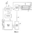
- FIG. 3 shows a schematic diagram of the drive slip detection system for the printing device of FIG. 1 ;
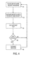
- FIG. 4 shows a flow diagram of a method of calculating slip using the drive slip detection system of FIG. 3 ;
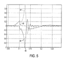
- FIG. 5 shows a graph of the detected slip in an exemplary printing device using the method of FIG. 4 .
- an exemplary printer with belt slip detection is shown in the form of a solid ink printer 10.
- the printer 10 includes a rotatable imaging drum 12.
- the imaging drum 12 is driven by a motor (not shown in FIG. 1 ).
- Solid ink 14 in the printer 10 is melted and a printhead 15 deposits the melted ink on the imaging drum 12.
- the imaging drum 12, ink 14, printhead 15 and motor are all situated within a housing 18 of the printer.
- the word “printer”, “printing device” or “printing system” as used herein encompasses any apparatus, such as a digital copier, bookmaking machine, facsimile machine, multi-function machine, etc. which performs a print outputting function for any purpose.
- the term “marking material” as used herein encompasses any colorant or other material used to mark on paper or other media. Examples of marking material include inks, toner particles, pigments, and dyes.
- the imaging drum 12 is driven by an electric motor 20 and belt drive system.
- the drive system includes a drive belt 22 connected between a motor pulley 24 (not shown in FIG. 2 ) and a drum pulley 26.
- FIG. 2 shows a perspective view of the motor 20, belt 22 and drum pulley 26.
- FIG. 3 shows a schematic view of the motor 20 and drive system.
- the motor pulley 24 is generally cylindrical with a cross section of external grooves that receives a similar cross section of mating ribs provided along the inner circumferential portion of the belt 22.
- the motor pulley 24 is connected to the motor shaft 23 and is driven by the electric motor 20.
- the motor 20 may be any of various electric motors appropriate for use in a printer (such as a three phase synchronous brushless motor).
- the drive belt 22 is connected between the motor pulley 24 and the drum pulley 26.
- the drive belt 22 is a v-belt or muli-ribbed v-belt which may be reinforced with fibers such as steel, Kevlar, or polyester.
- the "V" section of the belt 22 mates with the grooves on the motor pulley 24 and prevents the belt from tracking off of the motor pulley 24.
- Belt tension causes the "V" shaped ribs on the belt 22 to wedge into the mating grooves at the motor pulley 24. This wedging action improves the torque transmission capacity of the belt drive system.
- the drum pulley 26 is also cylindrical and is mechanically linked to the motor pulley 24 via the belt 22.
- the v-belt is received by the drum pulley 26 along this flat outer circumferential portion 28. Belt slip may occur at either the motor pulley 24 or the drum pulley 26 to belt interface.
- the imaging drum 12 is rigidly connected to the drum pulley 26 such that rotation of the drum pulley 26 directly results in rotation of the imaging drum 12. It will be recognized that the drum pulley 26 as well as the motor pulley 24 and motor 20 are also situated within the housing 18 of the printer 10 along with the imaging drum 12, as shown in FIG. 1 .
- the drum 12 and drum pulley 26 are mounted on a stationary mounting plate 30.
- the motor pulley 24 and motor 20 are mounted on a moveable mounting plate 32 which is configured to pivot about axis 33 relative to the stationary mounting plate 30.
- a spring 34 biases the plate 32 to pivot in a direction which encourages the motor pulley 24 and motor 20 away from the drum pulley 26.
- the spring 34 creates the tension on the belt 22 which mechanically links the motor pulley 24 to the drum pulley 26.
- a first sensor 40 which in one embodiment is provided in the form of a Hall effect sensor 40, is positioned inside the motor and is configured to track the motor rotor 21 position.
- the Hall effect sensor 40 is positioned across an air gap from rotor magnets 41 located inside the motor 20.
- a second sensor 42 which may also be in the form of a photo transmissive sensor, is positioned near the imaging drum shaft 25 and is configured to track the position of the imaging drum 12.
- the second sensor includes a rotatable encoder disc 43 mounted to the imaging drum shaft 25 and a stationary receptor 45 mounted to a bracket within the printer.
- the position sensors 40, 42 are each connected to a controller 44.
- the controller 44 may comprise, for example, a microprocessor and supporting circuitry.
- the first sensor 40 delivers signals to the controller 44 which are representative of the position of the motor rotor 21.
- the second sensor 42 delivers signals to the controller 44 which are representative of the position of the imaging drum 12.
- the controller 44 is able to calculate the respective angular velocities of the motor rotor 21 and the imaging drum 12.
- information about the no load drive ratio between the motor pulley 24 and the drum pulley 26 is stored in the controller 44.
- the controller 44 can then divide the velocity of the motor 20 by this no load drive ratio and subtract the result from the drum velocity in order to determine the amount of slip occurring.
- the calculated slip may then be used to trigger a fault condition or capture other measurements (e.g., motor current to determine drive torque).
- a current drive ratio can be determined.
- a change in the drive ratio over time can be used to provide an indication of belt wear.
- the imaging drum 12 is driven by the motor 20 and drive system. As the imaging drum 12 rotates, the controller 44 instructs the printhead 15 to deposit ink on the imaging drum 12. Paper or other media 16 is then passed between a transverse roller 11 and the surface of the imaging drum 12, causing the ink on the imaging drum 12 to be transferred to the media. If a slip event occurs during the printing process, the controller 44 is operable to identify the fault condition and trigger a fault response, such as limiting motor torque.
- a fault response such as limiting motor torque.
- FIG. 4 An exemplary method that may be used by the controller 44 to determine if a slip event is occurring is shown in FIG. 4 .
- the controller 44 receives a first signal from the sensor 40 positioned near the motor 20.
- the controller 44 receives a second signal from the sensor 42 positioned near the imaging drum 12.
- a velocity signal can be generated for both the imaging drum 12 and the drive motor 20.
- the controller 44 calculates an angular velocity for the motor rotor 21.
- the controller 44 calculates an angular velocity for the imaging drum 12.
- the controller calculates a belt slip.
- the belt slip may be calculated in several ways, as will be recognized by those of skill in the art.
- the belt slip is calculated by comparing the angular velocity of the motor rotor 21 to the angular velocity of the imaging drum 12.
- the angular velocity of the motor rotor 21 is first scaled to the angular velocity of the imaging drum 12 by the no load drive ratio.
- the difference between the scaled motor rotor velocity and the imaging drum velocity is the slip velocity or rate of slip of the friction drive.
- the change in motor rotor 21 and imaging drum 12 positions are sampled at approximately 20 kHz using the sensors 40, 42.
- the position change per unit time for each is the angular velocity.
- Dividing the motor rotor velocity by the no load drive ratio (e.g., approximately 10:1) scales it to an equivalent imaging drum velocity.
- Slip, in units of drum revolutions per second is calculated by the following equation:
- slip_velocity drum_veloeity - (motor_velocity / ratio).
- Imaging drum angular position may be recorded each time the motor rotor completes some number of revolutions. (This number of motor rotor revolutions may be less than one, such as the fraction of a revolution corresponding to one electrical cycle of the motor encoder signals.) Slip distance, in units of drum position per motor revolution is calculated as:
- slip_distance drum_pos_change / motor_pos_change - 1.0 / ratio.
- the graph in FIG. 5 illustrates an exemplary slip event.
- the vertical scale is revolutions per second (drum velocity) and the horizontal axis is time in seconds.
- Trace 60 in FIG. 5 shows drum velocity. It remains near zero during the exemplary slip event shown in FIG. 5 .
- Trace 61 in FIG. 5 shows motor velocity as it rapidly increases between 0.1 and 0.15 seconds and then decreases.
- Trace 64 in FIG. 5 shows the calculated slip.
- the drum drive system was allowed to operate until slip increased to a slip threshold of approximately one imaging drum revolution-per-second (absolute value) as indicated at point 66 on trace 64. It was previously determined that slip events in excess of one drum revolution-per-second are characteristically very noisy and may damage the belt 22. Limiting the slip in the example of FIG. 5 to a threshold of 1 drum revolution per second (absolute value) prevented offensive noise and minimized belt damage.
- the torque capacity of the belt drive can be determined.
- a slip event may be created by accelerating the imaging drum 12, thus using imaging drum inertia to create resistive torque to the motor 20.
- the torque at the motor pulley 24 required to create a given slip is calculated using motor current values that correspond to the slip measured.
- Total motor torque is the motor current multiplied by the motor torque constant.
- Motor pulley 24 torque is the total motor torque minus the torque required to accelerate the motor rotor 21.
- Belt drive torque capacity is equal to the motor pulley 24 torque capacity multiplied by the drive ratio. Accordingly, by detecting belt slip, the belt 22 can be protected from damage caused by excessive slip.
- belt slip can be used to identify faulty belt drive assemblies by measuring belt slip and motor current to quantify drive torque capacity.
- the drive system for the printer described herein may also be used to provide a system for detecting belt wear.
- an existing drive ratio for the printer can be determined.
- an indication of belt wear is provided.
- a worn belt rides lower in the grooves of the pulleys, reducing the effective diameter of the pulleys.
- a given change in effective pulley diameter has much more relative affect on the smaller motor pulley, so the drive ratio increases. Accordingly, an increase in the drive ratio of motor rotor revolutions to imaging drum revolutions occurs over time.
- the printer disclosed herein may be used to monitor belt wear.
- the controller 44 may be used to monitor the imaging drum 12 velocity and the motor rotor 21 velocity, and calculate the drive ratio for the drive system. The controller 44 may then determine the wear condition of the belt 22 based on the calculated drive ratio. In particular, if the drive ratio reaches a threshold, the printer may be equipped with an alarm or other warning (e.g., warning light 70 shown in FIG. 3 , or a text display on a screen) indicating that the belt 22 should be replaced.
- an alarm or other warning e.g., warning light 70 shown in FIG. 3 , or a text display on a screen
- belt drives are used to transmit power to many peripherals such as the alternator, power steering pump, water pump, air conditioner pump, etc.
- a car's on board diagnostics may be utilized to automatically determine excessive belt slip or wear for use in service diagnostics and or to initiate a service required indicator.
- ECM Engine Control Module
- Many modern engines use an Engine Control Module (ECM) that receives signals from a crank shaft position sensor.
- ECM Engine Control Module
- the sense signal may be simply and easily implemented within the alternator.
- a tachometer signal generated by the alternators internal changing magnetic field, may be routed to the ECU via a single wire using chassis ground as reference.
Landscapes
- Physics & Mathematics (AREA)
- General Physics & Mathematics (AREA)
- Devices For Conveying Motion By Means Of Endless Flexible Members (AREA)
- Accessory Devices And Overall Control Thereof (AREA)
- Ink Jet (AREA)
- Length Measuring Devices By Optical Means (AREA)
- Controlling Sheets Or Webs (AREA)
Abstract
Description
- The embodiments disclosed herein relate to the field of printing and specifically to a printing device and related method for detecting the slip of a drive belt in the printing device.
- Many printing devices use a rotating imaging member that receives marking material and transfers the marking material to print media. For example, solid ink printers include a rotating imaging drum. The solid ink in the printer is melted and deposited on to the drum. The drum then transfers the ink to paper.
- The imaging drum in such printing devices is rotated and the paper comes into contact with the drum as it rotates. An electric motor is used to rotate the drum via a drive mechanism. The drive mechanism may include a gear drive as well as a drive belt which is operably connected between a motor pulley and a drum pulley. The drive belt is typically provided in the form of a v-belt which links the motor pulley to the drum pulley. The motor pulley is grooved to match the belt profile and the drum pulley may be grooved or flat. The v-belt relies on friction to transmit torque between the drive motor and the drum. The torque capacity of the printer is dependent in part on the belt tension and the coefficient of friction between the belt and pulleys.
- In certain situations, the friction between the belt and the pulleys is insufficient to drive the imaging drum and the belt slips on one of the pulleys. Excessive belt slip between the motor and the drum may result in belt damage and objectionable noise.
- A number of factors can cause variation in the torque capacity of the belt drive system. These factors include, but are not limited to (i) residual mold release agent being left on new belts; (ii) drum release agent (e.g., silicone oil) contaminating the belt or pulleys; (iii) improper belt tension as a result of various factors (e.g., improper spring installation or improper binding of the motor pivot interface); and (iv) belt wear.
- Even if the belt is clean from contaminates, relatively new, and properly tensioned, a "normal" belt drive may slip when an unexpected high torque event occurs. Such unexpected high torque events include, but are not limited to (i) pressure roller attempts to climb a leading media edge under an excessive transfix load; (ii) multipick or shingled media delivered to the transfix nip causing the pressure roller to climb the leading edge of the shingled media; (iii) commanding excessive drum accelerations; (iv) a loss of servo control of the drum drive yielding unexpected high accelerations; or (v) an excessive transfix load.
- In view of the foregoing, it would be desirable to provide a printing system capable of preventing belt damage or excessive noise due to belt slip. It would also be desirable to provide such a system that may also be used to identify a faulty drive system, worn belt, or events that cause excessive belt slip.
- A method of detecting drive belt slip in a printing device comprises driving an imaging member using a motor and a drive belt. During operation of the printing device, a first drive parameter related to the motor is determined, such as, for example, the angular velocity of the motor rotor. Also during operation of the printing device, a second drive parameter related to the imaging member is determined, such as, for example, the angular velocity of the imaging member. A slip of the drive belt is then determined based on the first drive parameter and the second drive parameter. In one embodiment, the slip is a rate of slip determined by subtracting a scaled amount of the first velocity from the second velocity. If the rate of slip exceeds a threshold amount, a slip event is declared.
- In at least one embodiment, a printing device configured to detect drive belt slip comprises a motor and a first sensor configured to provide a first signal based on rotation of the motor. The first sensor may be a rotational encoder such as, for example, a hall-effect sensor configured to provide a signal indicative of the angular velocity of the motor rotor. The printing device further comprises a belt operably connected to the motor and an imaging drum operably connected to the belt such that the motor is configured to drive the drum via the belt. A second sensor is configured to provide a second signal based on rotation of the imaging drum. The second sensor may be a rotational encoder such as, for example, an optical or photo-transmissive sensor provided on the imaging drum axis of rotation and configured to provide a signal indicative of an angular velocity of the imaging drum. A controller is configured to receive the first signal and the second signal and determine the slip of the belt based on the first signal and the second signal. In at least one embodiment, the controller is configured to determine a slip velocity by subtracting a scaled amount of the angular velocity of the motor rotor from the angular velocity of the imaging drum. Furthermore, the controller is configured to determine excessive slip velocity exceeding a threshold amount and trigger a response to minimize belt slip noise and belt damage.
In one embodiment of the printing device ofclaim 15 the controller is configured to determine the slip velocity by subtracting a scaled amount of the angular velocity of the rotor from the angular velocity of the imaging member.
In a further embodiment the controller is further configured to limit the motor torque when the slip exceeds a threshold amount.
According to another aspect a printing device comprises: - a motor including a rotor;
- a first sensor configured to provide a first signal based on rotation of the rotor;
- a belt operably connected to the motor;
- an imaging member operably connected to the belt;
- a printhead configured to deposit marking material on the imaging member;
- a second sensor configured to provide a second signal based on rotation of the imaging member; and
- a controller configured to receive the first signal and the second signal and determine a drive ratio based on the first signal and the second signal.
- The above described features and advantages, as well as others, will become more readily apparent to those of ordinary skill in the art by reference to the following detailed description and accompanying drawings. While it would be desirable to provide a method and system for detecting drum drive belt slip that provides one or more of these or other advantageous features as may be apparent to those reviewing this disclosure, the teachings disclosed herein extend to those embodiments which fall within the scope of the appended claims, regardless of whether they include or accomplish one or more of the above-mentioned advantages or features.
-
FIG. 1 shows a cutaway view of an exemplary printing device with drive slip detection; -
FIG. 2 shows a perspective view of a drum drive system for the printing device ofFIG. 1 ; -
FIG. 3 shows a schematic diagram of the drive slip detection system for the printing device ofFIG. 1 ; -
FIG. 4 shows a flow diagram of a method of calculating slip using the drive slip detection system ofFIG. 3 ; and -
FIG. 5 shows a graph of the detected slip in an exemplary printing device using the method ofFIG. 4 . - With reference to
FIG. 1 , an exemplary printer with belt slip detection is shown in the form of asolid ink printer 10. Theprinter 10 includes arotatable imaging drum 12. Theimaging drum 12 is driven by a motor (not shown inFIG. 1 ).Solid ink 14 in theprinter 10 is melted and aprinthead 15 deposits the melted ink on theimaging drum 12. Theimaging drum 12,ink 14,printhead 15 and motor are all situated within ahousing 18 of the printer. Whenpaper 16 is fed through theprinter 10 and brought into contact withimaging drum 12, the ink on the drum is transferred from theimaging drum 12 to thepaper 16 to create a desired image. The word "printer", "printing device" or "printing system" as used herein encompasses any apparatus, such as a digital copier, bookmaking machine, facsimile machine, multi-function machine, etc. which performs a print outputting function for any purpose. The term "marking material" as used herein encompasses any colorant or other material used to mark on paper or other media. Examples of marking material include inks, toner particles, pigments, and dyes. - With reference now to
FIGs. 2-3 , theimaging drum 12 is driven by anelectric motor 20 and belt drive system. The drive system includes adrive belt 22 connected between a motor pulley 24 (not shown inFIG. 2 ) and adrum pulley 26.FIG. 2 shows a perspective view of themotor 20,belt 22 and drumpulley 26.FIG. 3 shows a schematic view of themotor 20 and drive system. - The
motor pulley 24 is generally cylindrical with a cross section of external grooves that receives a similar cross section of mating ribs provided along the inner circumferential portion of thebelt 22. Themotor pulley 24 is connected to the motor shaft 23 and is driven by theelectric motor 20. Themotor 20 may be any of various electric motors appropriate for use in a printer (such as a three phase synchronous brushless motor). - The
drive belt 22 is connected between themotor pulley 24 and thedrum pulley 26. In at least one embodiment, thedrive belt 22 is a v-belt or muli-ribbed v-belt which may be reinforced with fibers such as steel, Kevlar, or polyester. The "V" section of thebelt 22 mates with the grooves on themotor pulley 24 and prevents the belt from tracking off of themotor pulley 24. Belt tension causes the "V" shaped ribs on thebelt 22 to wedge into the mating grooves at themotor pulley 24. This wedging action improves the torque transmission capacity of the belt drive system. - The
drum pulley 26 is also cylindrical and is mechanically linked to themotor pulley 24 via thebelt 22. The v-belt is received by thedrum pulley 26 along this flat outercircumferential portion 28. Belt slip may occur at either themotor pulley 24 or thedrum pulley 26 to belt interface. - The
imaging drum 12 is rigidly connected to thedrum pulley 26 such that rotation of thedrum pulley 26 directly results in rotation of theimaging drum 12. It will be recognized that thedrum pulley 26 as well as themotor pulley 24 andmotor 20 are also situated within thehousing 18 of theprinter 10 along with theimaging drum 12, as shown inFIG. 1 . - As best seen in
FIG. 2 , thedrum 12 and drumpulley 26 are mounted on astationary mounting plate 30. Themotor pulley 24 andmotor 20 are mounted on a moveable mountingplate 32 which is configured to pivot aboutaxis 33 relative to the stationary mountingplate 30. Aspring 34 biases theplate 32 to pivot in a direction which encourages themotor pulley 24 andmotor 20 away from thedrum pulley 26. Thus, thespring 34 creates the tension on thebelt 22 which mechanically links themotor pulley 24 to thedrum pulley 26. - With particular reference now to
FIG. 3 , afirst sensor 40, which in one embodiment is provided in the form of aHall effect sensor 40, is positioned inside the motor and is configured to track themotor rotor 21 position. In at least one embodiment, theHall effect sensor 40 is positioned across an air gap fromrotor magnets 41 located inside themotor 20. Asecond sensor 42, which may also be in the form of a photo transmissive sensor, is positioned near theimaging drum shaft 25 and is configured to track the position of theimaging drum 12. In at least one embodiment, the second sensor includes arotatable encoder disc 43 mounted to theimaging drum shaft 25 and astationary receptor 45 mounted to a bracket within the printer. Theposition sensors controller 44. Thecontroller 44 may comprise, for example, a microprocessor and supporting circuitry. - The
first sensor 40 delivers signals to thecontroller 44 which are representative of the position of themotor rotor 21. Similarly, thesecond sensor 42 delivers signals to thecontroller 44 which are representative of the position of theimaging drum 12. With this information thecontroller 44 is able to calculate the respective angular velocities of themotor rotor 21 and theimaging drum 12. Furthermore, information about the no load drive ratio between themotor pulley 24 and thedrum pulley 26 is stored in thecontroller 44. Thecontroller 44 can then divide the velocity of themotor 20 by this no load drive ratio and subtract the result from the drum velocity in order to determine the amount of slip occurring. The calculated slip may then be used to trigger a fault condition or capture other measurements (e.g., motor current to determine drive torque). Furthermore, by monitoring both the velocity of theimaging drum 12 and the velocity of themotor 20 independently, a current drive ratio can be determined. As explained in further detail below, a change in the drive ratio over time can be used to provide an indication of belt wear. - During operation of the printing device, the
imaging drum 12 is driven by themotor 20 and drive system. As theimaging drum 12 rotates, thecontroller 44 instructs theprinthead 15 to deposit ink on theimaging drum 12. Paper orother media 16 is then passed between a transverse roller 11 and the surface of theimaging drum 12, causing the ink on theimaging drum 12 to be transferred to the media. If a slip event occurs during the printing process, thecontroller 44 is operable to identify the fault condition and trigger a fault response, such as limiting motor torque. - An exemplary method that may be used by the
controller 44 to determine if a slip event is occurring is shown inFIG. 4 . According to the exemplary method, atstep 50, thecontroller 44 receives a first signal from thesensor 40 positioned near themotor 20. At the same time, thecontroller 44 receives a second signal from thesensor 42 positioned near theimaging drum 12. With a history of information on the motor position and drum position, a velocity signal can be generated for both theimaging drum 12 and thedrive motor 20. Thus, atstep 52, thecontroller 44 calculates an angular velocity for themotor rotor 21. At the same time, thecontroller 44 calculates an angular velocity for theimaging drum 12. - At
step 54, the controller calculates a belt slip. The belt slip may be calculated in several ways, as will be recognized by those of skill in the art. In at least one embodiment, the belt slip is calculated by comparing the angular velocity of themotor rotor 21 to the angular velocity of theimaging drum 12. Using this method, the angular velocity of themotor rotor 21 is first scaled to the angular velocity of theimaging drum 12 by the no load drive ratio. The difference between the scaled motor rotor velocity and the imaging drum velocity is the slip velocity or rate of slip of the friction drive. In at least one exemplary embodiment, the change inmotor rotor 21 andimaging drum 12 positions are sampled at approximately 20 kHz using thesensors - slip_velocity = drum_veloeity - (motor_velocity / ratio).
- Alternately, differences in position can be used to calculate belt slip. Imaging drum angular position may be recorded each time the motor rotor completes some number of revolutions. (This number of motor rotor revolutions may be less than one, such as the fraction of a revolution corresponding to one electrical cycle of the motor encoder signals.) Slip distance, in units of drum position per motor revolution is calculated as:
- slip_distance = drum_pos_change / motor_pos_change - 1.0 / ratio.
- The graph in
FIG. 5 illustrates an exemplary slip event. The vertical scale is revolutions per second (drum velocity) and the horizontal axis is time in seconds.Trace 60 inFIG. 5 shows drum velocity. It remains near zero during the exemplary slip event shown inFIG. 5 .Trace 61 inFIG. 5 shows motor velocity as it rapidly increases between 0.1 and 0.15 seconds and then decreases.Trace 64 inFIG. 5 shows the calculated slip. - In the example of
FIG. 5 , the drum drive system was allowed to operate until slip increased to a slip threshold of approximately one imaging drum revolution-per-second (absolute value) as indicated atpoint 66 ontrace 64. It was previously determined that slip events in excess of one drum revolution-per-second are characteristically very noisy and may damage thebelt 22. Limiting the slip in the example ofFIG. 5 to a threshold of 1 drum revolution per second (absolute value) prevented offensive noise and minimized belt damage. - In the example of
FIG. 5 , when the slip reached the threshold set at 1 (i.e.,point 66 on trace 64), a slip fault condition was declared. As a result, thecontroller 44 immediately took steps to limit the torque output of themotor 20. In this case, themotor 20 was disabled. In other embodiments, other responses to limit slip are possible. For example, rather than a response that completely disables themotor 20, the motor command current can be reduced. This in effect limits the drive torque of themotor 20. - By measuring belt slip and motor current together, the torque capacity of the belt drive can be determined. A slip event may be created by accelerating the
imaging drum 12, thus using imaging drum inertia to create resistive torque to themotor 20. The torque at themotor pulley 24 required to create a given slip is calculated using motor current values that correspond to the slip measured. Total motor torque is the motor current multiplied by the motor torque constant.Motor pulley 24 torque is the total motor torque minus the torque required to accelerate themotor rotor 21. Belt drive torque capacity is equal to themotor pulley 24 torque capacity multiplied by the drive ratio. Accordingly, by detecting belt slip, thebelt 22 can be protected from damage caused by excessive slip. In addition, belt slip can be used to identify faulty belt drive assemblies by measuring belt slip and motor current to quantify drive torque capacity. - In addition to providing a system for detecting belt slip, the drive system for the printer described herein may also be used to provide a system for detecting belt wear. In particular, by monitoring both the imaging drum and motor velocities independently, an existing drive ratio for the printer can be determined. By monitoring changes in the drive ratio over time, an indication of belt wear is provided. A worn belt rides lower in the grooves of the pulleys, reducing the effective diameter of the pulleys. A given change in effective pulley diameter has much more relative affect on the smaller motor pulley, so the drive ratio increases. Accordingly, an increase in the drive ratio of motor rotor revolutions to imaging drum revolutions occurs over time. When the mass of the belt is plotted against the drive ratio over time, a relatively linear relationship will be seen between belt mass and drive ratio. In at least one embodiment of the printer described herein, a new belt with a mass of about 21 grams provides a drive ratio of approximately 9.9:1, while a belt worn to near failure with a mass of 11 grams provides a drive ratio of approximately 10.9:1. A relatively linear relationship between belt mass and drive ratio can be seen in between these two points.
- In view of the foregoing, the printer disclosed herein may be used to monitor belt wear. For example, with reference again to
FIG. 3 , thecontroller 44 may be used to monitor theimaging drum 12 velocity and themotor rotor 21 velocity, and calculate the drive ratio for the drive system. Thecontroller 44 may then determine the wear condition of thebelt 22 based on the calculated drive ratio. In particular, if the drive ratio reaches a threshold, the printer may be equipped with an alarm or other warning (e.g., warninglight 70 shown inFIG. 3 , or a text display on a screen) indicating that thebelt 22 should be replaced. - It will be recognized that the techniques disclosed herein for determining belt slip and wear may have applications beyond printer technologies. For example, in the automotive industry belt drives are used to transmit power to many peripherals such as the alternator, power steering pump, water pump, air conditioner pump, etc. In one embodiment, a car's on board diagnostics may be utilized to automatically determine excessive belt slip or wear for use in service diagnostics and or to initiate a service required indicator. Many modern engines use an Engine Control Module (ECM) that receives signals from a crank shaft position sensor. Thus, the engine position and velocity information is already available. By adding a sense signal to one or more peripheral devices, here to the belt slip, ratio and wear could be monitored. In one embodiment, the sense signal may be simply and easily implemented within the alternator. A tachometer signal, generated by the alternators internal changing magnetic field, may be routed to the ECU via a single wire using chassis ground as reference.
- Although the various embodiments have been provided herein, it will be appreciated by those of skill in the art that other implementations and adaptations are possible. Furthermore, aspects of the various embodiments described herein may be combined or substituted with aspects from other features to arrive at different embodiments from those described herein. CLAIMS
In a further embodiment the controller is further configured to deliver a signal indicative of excessive belt slip or belt wear if the drive ratio passes the threshold drive ratio.
Claims (15)
- A method of operating a printing device comprising:a) driving an imaging member using a motor and a drive belt;b) depositing marking material on the imaging member using a printhead;c) determining a first drive parameter related to the motor;d) determining a second drive parameter related to the imaging member; ande) determining a slip of the drive belt based on the first drive parameter and the second drive parameter.
- The method of claim 1 wherein the step of driving the imaging member comprises driving an imaging drum, wherein the drive belt is operably connected between the imaging drum and the motor.
- The method of claim 1 wherein the first drive parameter is a first velocity of the motor, the second drive parameter is a second velocity of the imaging member, and the slip is a rate of slip of the drive belt.
- The method of claim 1 wherein the step of determining the second drive parameter comprises determining an angular velocity of the imaging member.
- The method of claim 4 wherein the step of determining the second drive parameter comprises receiving a signal indicative of the angular velocity of the imaging member from a rotational encoder.
- The method of claim 3 wherein the step of determining the rate of slip for the drive belt comprises determining a slip velocity by subtracting a scaled first velocity from the second velocity.
- The method of claim 6 wherein the scaled first velocity is obtained by dividing the first velocity by a no load drive ratio of the first velocity to the second velocity.
- The method of claim 1 further comprising the step of limiting motor torque when the slip exceeds a threshold amount.
- The method of claim 8 wherein the step of limiting motor torque comprises disabling the motor or limiting the motor current.
- The method of claim 1 further comprising the step of providing an indication of the condition of the drive belt based on the determined slip.
- The method of claim 1 further comprising the step of providing an indication of belt wear based on a no load drive ratio determined by the first and second drive parameters.
- A printing device comprising:a motor including a rotor;a first sensor configured to provide a first signal based on rotation of the rotor;a belt operably connected to the motor;an imaging member operably connected to the belt;a printhead configured to deposit marking material on the imaging member;a second sensor configured to provide a second signal based on rotation of the imaging member; anda controller configured to receive the first signal and the second signal and determine a slip of the belt based on the first signal and the second signal.
- The printing device of claim 12 wherein the first sensor is a hall-effect sensor or a photo-sensor and the first signal is a signal indicative of an angular velocity of the rotor, and wherein the second sensor is a hall-effect sensor or a photo sensor and the second signal is a signal indicative of an angular velocity of the imaging member.
- The printing device of claim 12 wherein the imaging member is an imaging drum.
- The printing device of claim 12 wherein the first signal is a signal indicative of an angular velocity of the rotor, the second signal is a signal indicative of an angular velocity of the imaging member, and wherein the controller is configured to determine a slip velocity.
Applications Claiming Priority (1)
| Application Number | Priority Date | Filing Date | Title |
|---|---|---|---|
| US12/208,442 US8226185B2 (en) | 2008-09-11 | 2008-09-11 | Drive belt slip and belt wear detection |
Publications (2)
| Publication Number | Publication Date |
|---|---|
| EP2163951A1 true EP2163951A1 (en) | 2010-03-17 |
| EP2163951B1 EP2163951B1 (en) | 2016-12-28 |
Family
ID=41397485
Family Applications (1)
| Application Number | Title | Priority Date | Filing Date |
|---|---|---|---|
| EP09169311.9A Not-in-force EP2163951B1 (en) | 2008-09-11 | 2009-09-03 | Drive belt slip and belt wear detection |
Country Status (7)
| Country | Link |
|---|---|
| US (1) | US8226185B2 (en) |
| EP (1) | EP2163951B1 (en) |
| JP (1) | JP5250515B2 (en) |
| KR (1) | KR101253070B1 (en) |
| CN (1) | CN101708670B (en) |
| BR (1) | BRPI0903307A2 (en) |
| MX (1) | MX2009009467A (en) |
Families Citing this family (14)
| Publication number | Priority date | Publication date | Assignee | Title |
|---|---|---|---|---|
| US7979176B2 (en) * | 2008-02-01 | 2011-07-12 | GM Global Technology Operations LLC | Serpentine belt useful life monitor |
| US8668326B2 (en) * | 2011-02-15 | 2014-03-11 | Xerox Corporation | Drum maintenance system with leak detection |
| US8755589B2 (en) | 2011-09-06 | 2014-06-17 | The Gates Corporation | Measurement of belt wear through edge detection of a raster image |
| JP2013145316A (en) * | 2012-01-13 | 2013-07-25 | Canon Inc | Image forming apparatus, control method thereof and program |
| US9098914B2 (en) | 2013-03-11 | 2015-08-04 | Gates Corporation | Enhanced analysis for image-based serpentine belt wear evaluation |
| GB2524023B (en) * | 2014-03-11 | 2017-10-18 | Ford Global Tech Llc | Belt slip monitor |
| US10118802B2 (en) | 2014-10-31 | 2018-11-06 | Otis Elevator Company | Structural health monitoring of an escalator drive system |
| BR112017023848B1 (en) * | 2015-05-07 | 2021-01-26 | Walther Flender Gmbh | method for monitoring a belt drive and belt drive |
| DE102016206849B4 (en) * | 2016-04-22 | 2026-04-30 | Robert Bosch Gesellschaft mit beschränkter Haftung | Method for determining belt wear in a belt drive and belt drive |
| JP6530731B2 (en) * | 2016-09-01 | 2019-06-12 | ファナック株式会社 | Numerical control device |
| CA3122836C (en) | 2017-01-20 | 2025-04-01 | Polaris Industries Inc. | Diagnostic systems and methods of a continuously variable transmission |
| CN114609405B (en) * | 2020-12-08 | 2023-07-11 | 泰富重工制造有限公司 | Method for testing speed of downward belt |
| TWI799986B (en) * | 2021-09-13 | 2023-04-21 | 新代科技股份有限公司 | Detection system for transmission belt and detection method thereof |
| DE102022110168B3 (en) | 2022-04-27 | 2023-05-17 | Heidelberger Druckmaschinen Aktiengesellschaft | Functional monitoring of conveyor belts in the printing press |
Citations (5)
| Publication number | Priority date | Publication date | Assignee | Title |
|---|---|---|---|---|
| JPH01288656A (en) | 1988-05-13 | 1989-11-20 | Mazda Motor Corp | Method for detecting slip ratio and method for adjusting belt tension of accessory driving belt |
| EP0767055A2 (en) | 1995-10-04 | 1997-04-09 | MAN Roland Druckmaschinen AG | Monitoring device for the driving device of a printing machine |
| JP2002311672A (en) | 2001-04-19 | 2002-10-23 | Ricoh Co Ltd | Image forming device |
| EP1818572A1 (en) | 2002-12-23 | 2007-08-15 | Van Doorne's Transmissie B.V. | Method for operating a continuously variable transmission |
| WO2008078980A1 (en) | 2006-12-27 | 2008-07-03 | Robert Bosch Gmbh | Method for determining slip in a friction-type continuously variable transmission and a transmission equiped with means for carrying out the method |
Family Cites Families (20)
| Publication number | Priority date | Publication date | Assignee | Title |
|---|---|---|---|---|
| JPS60100015A (en) * | 1983-11-07 | 1985-06-03 | Tamagawa Seiki Kk | Rotary encoder |
| JPH0687212A (en) * | 1992-09-04 | 1994-03-29 | Seiko Epson Corp | Transfer type inkjet recording device |
| JP3211845B2 (en) * | 1992-11-20 | 2001-09-25 | セイコーエプソン株式会社 | Transfer-type inkjet recording device |
| JP3213862B2 (en) * | 1993-06-08 | 2001-10-02 | セイコーエプソン株式会社 | Transfer-type inkjet recording device |
| US5406359A (en) * | 1993-09-24 | 1995-04-11 | Xerox Corporation | Ultra-high efficiency intermediate transfer with pre-transfer treatment on an imaging drum and an intermediate belt |
| US5418600A (en) * | 1993-12-17 | 1995-05-23 | Xerox Corporation | Conformable friction drive system for belt or drum transport |
| IL116123A (en) * | 1995-11-23 | 1999-07-14 | Scitex Corp Ltd | System and method for printing |
| JPH10166671A (en) * | 1996-12-06 | 1998-06-23 | Canon Inc | Motor drive control method for image forming apparatus and motor drive control apparatus using the method |
| US5940105A (en) * | 1996-01-26 | 1999-08-17 | Canon Kabushiki Kaisha | Motor drive controlling method for an image forming apparatus and motor drive controlling apparatus in the image forming apparatus using the method |
| JP3330543B2 (en) * | 1998-07-17 | 2002-09-30 | 株式会社日立ビルシステム | Belt diagnostic device for passenger conveyor drive |
| JP3652177B2 (en) * | 1999-08-20 | 2005-05-25 | 株式会社デンソー | Belt transmission system for internal combustion engines |
| JP3309183B2 (en) * | 2000-04-20 | 2002-07-29 | 井上金属工業株式会社 | Endless belt equipment |
| JP2002221887A (en) * | 2001-01-25 | 2002-08-09 | Ricoh Co Ltd | Drive control device for rotating body |
| JP4440666B2 (en) * | 2004-02-16 | 2010-03-24 | 株式会社リコー | Process cartridge mounting mechanism and image forming apparatus |
| JP2006038943A (en) * | 2004-07-22 | 2006-02-09 | Ricoh Co Ltd | Mark detection circuit, drive control device, and image forming apparatus |
| US7155144B2 (en) * | 2004-07-30 | 2006-12-26 | Xerox Corporation | Photoreceptor belt tensioner providing low variation in belt tension as a function of belt length |
| JP4568609B2 (en) * | 2005-01-11 | 2010-10-27 | 株式会社リコー | Image forming apparatus |
| JP2007114290A (en) * | 2005-10-18 | 2007-05-10 | Fuji Xerox Co Ltd | Image forming apparatus |
| JP2007137535A (en) * | 2005-11-15 | 2007-06-07 | Ricoh Co Ltd | Belt drive control device and image forming apparatus having the same |
| US7556337B2 (en) * | 2006-11-02 | 2009-07-07 | Xerox Corporation | System and method for evaluating line formation in an ink jet imaging device to normalize print head driving voltages |
-
2008
- 2008-09-11 US US12/208,442 patent/US8226185B2/en not_active Expired - Fee Related
-
2009
- 2009-09-03 EP EP09169311.9A patent/EP2163951B1/en not_active Not-in-force
- 2009-09-04 MX MX2009009467A patent/MX2009009467A/en active IP Right Grant
- 2009-09-08 JP JP2009206741A patent/JP5250515B2/en not_active Expired - Fee Related
- 2009-09-10 BR BRPI0903307-6A patent/BRPI0903307A2/en not_active IP Right Cessation
- 2009-09-10 CN CN200910161973.2A patent/CN101708670B/en not_active Expired - Fee Related
- 2009-09-10 KR KR1020090085187A patent/KR101253070B1/en not_active Expired - Fee Related
Patent Citations (5)
| Publication number | Priority date | Publication date | Assignee | Title |
|---|---|---|---|---|
| JPH01288656A (en) | 1988-05-13 | 1989-11-20 | Mazda Motor Corp | Method for detecting slip ratio and method for adjusting belt tension of accessory driving belt |
| EP0767055A2 (en) | 1995-10-04 | 1997-04-09 | MAN Roland Druckmaschinen AG | Monitoring device for the driving device of a printing machine |
| JP2002311672A (en) | 2001-04-19 | 2002-10-23 | Ricoh Co Ltd | Image forming device |
| EP1818572A1 (en) | 2002-12-23 | 2007-08-15 | Van Doorne's Transmissie B.V. | Method for operating a continuously variable transmission |
| WO2008078980A1 (en) | 2006-12-27 | 2008-07-03 | Robert Bosch Gmbh | Method for determining slip in a friction-type continuously variable transmission and a transmission equiped with means for carrying out the method |
Also Published As
| Publication number | Publication date |
|---|---|
| MX2009009467A (en) | 2010-03-10 |
| KR101253070B1 (en) | 2013-04-11 |
| US8226185B2 (en) | 2012-07-24 |
| JP5250515B2 (en) | 2013-07-31 |
| KR20100031079A (en) | 2010-03-19 |
| CN101708670B (en) | 2014-04-09 |
| US20100060677A1 (en) | 2010-03-11 |
| BRPI0903307A2 (en) | 2010-11-03 |
| CN101708670A (en) | 2010-05-19 |
| EP2163951B1 (en) | 2016-12-28 |
| JP2010064484A (en) | 2010-03-25 |
Similar Documents
| Publication | Publication Date | Title |
|---|---|---|
| US8226185B2 (en) | Drive belt slip and belt wear detection | |
| US7174264B2 (en) | Fault diagnosis apparatus | |
| US8160467B2 (en) | Apparatus and method for print apparatus rotational assembly cleaning blade adjustment | |
| EP1509467B1 (en) | Displacement measurement system and sheet feed system incorporating the same | |
| US8351804B2 (en) | Fixing apparatus | |
| JPH05238599A (en) | Device for sheet misfeed and jam detection | |
| US20100052242A1 (en) | Warpage leveling unit, warpage leveling device, image forming apparatus and warpage leveling processing program | |
| CN107357152B (en) | Imaging device | |
| US20120065931A1 (en) | Sheet thickness measurement apparatus | |
| US8861997B2 (en) | Rotary driving apparatus, control method therefor, storage medium storing control program therefor, and image forming apparatus | |
| SE520322C2 (en) | Method and apparatus for spacing between a stator and a rotating rotor opposed thereto | |
| KR101671634B1 (en) | Method for determining the amount of wear quantity for shaft parts of power transmission system | |
| US12085476B2 (en) | Method for monitoring at least one bearing of a motor vehicle, in particular of a motorized vehicle, and motor vehicle | |
| US8548341B2 (en) | Image forming apparatus provided with mechanism for cleaning image carrier | |
| JP2774269B2 (en) | Monitoring device for drive of printing press | |
| JP2009052692A (en) | Electromagnetic clutch, transport roller, and image forming apparatus including the same | |
| JP7276977B1 (en) | Printer and printer control method | |
| JP4621507B2 (en) | Image forming apparatus | |
| JP6123775B2 (en) | Occupant detection device and seat belt abnormality determination device | |
| JP4565687B2 (en) | Measuring roller system | |
| JP2019085222A (en) | Image forming apparatus and method and program for predicting roller service life | |
| JP5045075B2 (en) | Image forming apparatus | |
| KR20120116741A (en) | Velocity detecting apparatus for electric bicycle | |
| JP2016150513A (en) | Intaglio printing machine including management mechanism for wiping-roller surface temperature | |
| JP2008051965A (en) | Image processing apparatus and DC motor control method |
Legal Events
| Date | Code | Title | Description |
|---|---|---|---|
| PUAI | Public reference made under article 153(3) epc to a published international application that has entered the european phase |
Free format text: ORIGINAL CODE: 0009012 |
|
| AK | Designated contracting states |
Kind code of ref document: A1 Designated state(s): AT BE BG CH CY CZ DE DK EE ES FI FR GB GR HR HU IE IS IT LI LT LU LV MC MK MT NL NO PL PT RO SE SI SK SM TR |
|
| AX | Request for extension of the european patent |
Extension state: AL BA RS |
|
| 17P | Request for examination filed |
Effective date: 20100917 |
|
| 17Q | First examination report despatched |
Effective date: 20160303 |
|
| GRAP | Despatch of communication of intention to grant a patent |
Free format text: ORIGINAL CODE: EPIDOSNIGR1 |
|
| INTG | Intention to grant announced |
Effective date: 20160906 |
|
| GRAS | Grant fee paid |
Free format text: ORIGINAL CODE: EPIDOSNIGR3 |
|
| GRAA | (expected) grant |
Free format text: ORIGINAL CODE: 0009210 |
|
| AK | Designated contracting states |
Kind code of ref document: B1 Designated state(s): AT BE BG CH CY CZ DE DK EE ES FI FR GB GR HR HU IE IS IT LI LT LU LV MC MK MT NL NO PL PT RO SE SI SK SM TR |
|
| REG | Reference to a national code |
Ref country code: GB Ref legal event code: FG4D |
|
| REG | Reference to a national code |
Ref country code: CH Ref legal event code: EP |
|
| REG | Reference to a national code |
Ref country code: AT Ref legal event code: REF Ref document number: 857815 Country of ref document: AT Kind code of ref document: T Effective date: 20170115 |
|
| REG | Reference to a national code |
Ref country code: IE Ref legal event code: FG4D |
|
| REG | Reference to a national code |
Ref country code: DE Ref legal event code: R096 Ref document number: 602009043339 Country of ref document: DE |
|
| PG25 | Lapsed in a contracting state [announced via postgrant information from national office to epo] |
Ref country code: LV Free format text: LAPSE BECAUSE OF FAILURE TO SUBMIT A TRANSLATION OF THE DESCRIPTION OR TO PAY THE FEE WITHIN THE PRESCRIBED TIME-LIMIT Effective date: 20161228 |
|
| REG | Reference to a national code |
Ref country code: LT Ref legal event code: MG4D |
|
| PG25 | Lapsed in a contracting state [announced via postgrant information from national office to epo] |
Ref country code: GR Free format text: LAPSE BECAUSE OF FAILURE TO SUBMIT A TRANSLATION OF THE DESCRIPTION OR TO PAY THE FEE WITHIN THE PRESCRIBED TIME-LIMIT Effective date: 20170329 Ref country code: LT Free format text: LAPSE BECAUSE OF FAILURE TO SUBMIT A TRANSLATION OF THE DESCRIPTION OR TO PAY THE FEE WITHIN THE PRESCRIBED TIME-LIMIT Effective date: 20161228 Ref country code: SE Free format text: LAPSE BECAUSE OF FAILURE TO SUBMIT A TRANSLATION OF THE DESCRIPTION OR TO PAY THE FEE WITHIN THE PRESCRIBED TIME-LIMIT Effective date: 20161228 Ref country code: NO Free format text: LAPSE BECAUSE OF FAILURE TO SUBMIT A TRANSLATION OF THE DESCRIPTION OR TO PAY THE FEE WITHIN THE PRESCRIBED TIME-LIMIT Effective date: 20170328 |
|
| REG | Reference to a national code |
Ref country code: NL Ref legal event code: MP Effective date: 20161228 |
|
| REG | Reference to a national code |
Ref country code: AT Ref legal event code: MK05 Ref document number: 857815 Country of ref document: AT Kind code of ref document: T Effective date: 20161228 |
|
| PG25 | Lapsed in a contracting state [announced via postgrant information from national office to epo] |
Ref country code: FI Free format text: LAPSE BECAUSE OF FAILURE TO SUBMIT A TRANSLATION OF THE DESCRIPTION OR TO PAY THE FEE WITHIN THE PRESCRIBED TIME-LIMIT Effective date: 20161228 Ref country code: HR Free format text: LAPSE BECAUSE OF FAILURE TO SUBMIT A TRANSLATION OF THE DESCRIPTION OR TO PAY THE FEE WITHIN THE PRESCRIBED TIME-LIMIT Effective date: 20161228 |
|
| PG25 | Lapsed in a contracting state [announced via postgrant information from national office to epo] |
Ref country code: NL Free format text: LAPSE BECAUSE OF FAILURE TO SUBMIT A TRANSLATION OF THE DESCRIPTION OR TO PAY THE FEE WITHIN THE PRESCRIBED TIME-LIMIT Effective date: 20161228 |
|
| PG25 | Lapsed in a contracting state [announced via postgrant information from national office to epo] |
Ref country code: IS Free format text: LAPSE BECAUSE OF FAILURE TO SUBMIT A TRANSLATION OF THE DESCRIPTION OR TO PAY THE FEE WITHIN THE PRESCRIBED TIME-LIMIT Effective date: 20170428 Ref country code: CZ Free format text: LAPSE BECAUSE OF FAILURE TO SUBMIT A TRANSLATION OF THE DESCRIPTION OR TO PAY THE FEE WITHIN THE PRESCRIBED TIME-LIMIT Effective date: 20161228 Ref country code: RO Free format text: LAPSE BECAUSE OF FAILURE TO SUBMIT A TRANSLATION OF THE DESCRIPTION OR TO PAY THE FEE WITHIN THE PRESCRIBED TIME-LIMIT Effective date: 20161228 Ref country code: EE Free format text: LAPSE BECAUSE OF FAILURE TO SUBMIT A TRANSLATION OF THE DESCRIPTION OR TO PAY THE FEE WITHIN THE PRESCRIBED TIME-LIMIT Effective date: 20161228 Ref country code: SK Free format text: LAPSE BECAUSE OF FAILURE TO SUBMIT A TRANSLATION OF THE DESCRIPTION OR TO PAY THE FEE WITHIN THE PRESCRIBED TIME-LIMIT Effective date: 20161228 |
|
| REG | Reference to a national code |
Ref country code: FR Ref legal event code: PLFP Year of fee payment: 9 |
|
| PG25 | Lapsed in a contracting state [announced via postgrant information from national office to epo] |
Ref country code: SM Free format text: LAPSE BECAUSE OF FAILURE TO SUBMIT A TRANSLATION OF THE DESCRIPTION OR TO PAY THE FEE WITHIN THE PRESCRIBED TIME-LIMIT Effective date: 20161228 Ref country code: ES Free format text: LAPSE BECAUSE OF FAILURE TO SUBMIT A TRANSLATION OF THE DESCRIPTION OR TO PAY THE FEE WITHIN THE PRESCRIBED TIME-LIMIT Effective date: 20161228 Ref country code: AT Free format text: LAPSE BECAUSE OF FAILURE TO SUBMIT A TRANSLATION OF THE DESCRIPTION OR TO PAY THE FEE WITHIN THE PRESCRIBED TIME-LIMIT Effective date: 20161228 Ref country code: IT Free format text: LAPSE BECAUSE OF FAILURE TO SUBMIT A TRANSLATION OF THE DESCRIPTION OR TO PAY THE FEE WITHIN THE PRESCRIBED TIME-LIMIT Effective date: 20161228 Ref country code: BG Free format text: LAPSE BECAUSE OF FAILURE TO SUBMIT A TRANSLATION OF THE DESCRIPTION OR TO PAY THE FEE WITHIN THE PRESCRIBED TIME-LIMIT Effective date: 20170328 Ref country code: PL Free format text: LAPSE BECAUSE OF FAILURE TO SUBMIT A TRANSLATION OF THE DESCRIPTION OR TO PAY THE FEE WITHIN THE PRESCRIBED TIME-LIMIT Effective date: 20161228 Ref country code: PT Free format text: LAPSE BECAUSE OF FAILURE TO SUBMIT A TRANSLATION OF THE DESCRIPTION OR TO PAY THE FEE WITHIN THE PRESCRIBED TIME-LIMIT Effective date: 20170428 Ref country code: BE Free format text: LAPSE BECAUSE OF FAILURE TO SUBMIT A TRANSLATION OF THE DESCRIPTION OR TO PAY THE FEE WITHIN THE PRESCRIBED TIME-LIMIT Effective date: 20161228 |
|
| REG | Reference to a national code |
Ref country code: DE Ref legal event code: R097 Ref document number: 602009043339 Country of ref document: DE |
|
| PLBE | No opposition filed within time limit |
Free format text: ORIGINAL CODE: 0009261 |
|
| STAA | Information on the status of an ep patent application or granted ep patent |
Free format text: STATUS: NO OPPOSITION FILED WITHIN TIME LIMIT |
|
| PG25 | Lapsed in a contracting state [announced via postgrant information from national office to epo] |
Ref country code: DK Free format text: LAPSE BECAUSE OF FAILURE TO SUBMIT A TRANSLATION OF THE DESCRIPTION OR TO PAY THE FEE WITHIN THE PRESCRIBED TIME-LIMIT Effective date: 20161228 |
|
| 26N | No opposition filed |
Effective date: 20170929 |
|
| PG25 | Lapsed in a contracting state [announced via postgrant information from national office to epo] |
Ref country code: SI Free format text: LAPSE BECAUSE OF FAILURE TO SUBMIT A TRANSLATION OF THE DESCRIPTION OR TO PAY THE FEE WITHIN THE PRESCRIBED TIME-LIMIT Effective date: 20161228 |
|
| REG | Reference to a national code |
Ref country code: CH Ref legal event code: PL |
|
| PG25 | Lapsed in a contracting state [announced via postgrant information from national office to epo] |
Ref country code: MC Free format text: LAPSE BECAUSE OF FAILURE TO SUBMIT A TRANSLATION OF THE DESCRIPTION OR TO PAY THE FEE WITHIN THE PRESCRIBED TIME-LIMIT Effective date: 20161228 |
|
| REG | Reference to a national code |
Ref country code: IE Ref legal event code: MM4A |
|
| PG25 | Lapsed in a contracting state [announced via postgrant information from national office to epo] |
Ref country code: LU Free format text: LAPSE BECAUSE OF NON-PAYMENT OF DUE FEES Effective date: 20170903 |
|
| PG25 | Lapsed in a contracting state [announced via postgrant information from national office to epo] |
Ref country code: LI Free format text: LAPSE BECAUSE OF NON-PAYMENT OF DUE FEES Effective date: 20170930 Ref country code: CH Free format text: LAPSE BECAUSE OF NON-PAYMENT OF DUE FEES Effective date: 20170930 Ref country code: IE Free format text: LAPSE BECAUSE OF NON-PAYMENT OF DUE FEES Effective date: 20170903 |
|
| REG | Reference to a national code |
Ref country code: FR Ref legal event code: PLFP Year of fee payment: 10 |
|
| PG25 | Lapsed in a contracting state [announced via postgrant information from national office to epo] |
Ref country code: MT Free format text: LAPSE BECAUSE OF NON-PAYMENT OF DUE FEES Effective date: 20170903 |
|
| PGFP | Annual fee paid to national office [announced via postgrant information from national office to epo] |
Ref country code: FR Payment date: 20180822 Year of fee payment: 10 Ref country code: DE Payment date: 20180821 Year of fee payment: 10 |
|
| PGFP | Annual fee paid to national office [announced via postgrant information from national office to epo] |
Ref country code: GB Payment date: 20180823 Year of fee payment: 10 |
|
| PG25 | Lapsed in a contracting state [announced via postgrant information from national office to epo] |
Ref country code: HU Free format text: LAPSE BECAUSE OF FAILURE TO SUBMIT A TRANSLATION OF THE DESCRIPTION OR TO PAY THE FEE WITHIN THE PRESCRIBED TIME-LIMIT; INVALID AB INITIO Effective date: 20090903 |
|
| PG25 | Lapsed in a contracting state [announced via postgrant information from national office to epo] |
Ref country code: CY Free format text: LAPSE BECAUSE OF NON-PAYMENT OF DUE FEES Effective date: 20161228 |
|
| PG25 | Lapsed in a contracting state [announced via postgrant information from national office to epo] |
Ref country code: MK Free format text: LAPSE BECAUSE OF FAILURE TO SUBMIT A TRANSLATION OF THE DESCRIPTION OR TO PAY THE FEE WITHIN THE PRESCRIBED TIME-LIMIT Effective date: 20161228 |
|
| PG25 | Lapsed in a contracting state [announced via postgrant information from national office to epo] |
Ref country code: TR Free format text: LAPSE BECAUSE OF FAILURE TO SUBMIT A TRANSLATION OF THE DESCRIPTION OR TO PAY THE FEE WITHIN THE PRESCRIBED TIME-LIMIT Effective date: 20161228 |
|
| REG | Reference to a national code |
Ref country code: DE Ref legal event code: R119 Ref document number: 602009043339 Country of ref document: DE |
|
| PG25 | Lapsed in a contracting state [announced via postgrant information from national office to epo] |
Ref country code: DE Free format text: LAPSE BECAUSE OF NON-PAYMENT OF DUE FEES Effective date: 20200401 |
|
| GBPC | Gb: european patent ceased through non-payment of renewal fee |
Effective date: 20190903 |
|
| PG25 | Lapsed in a contracting state [announced via postgrant information from national office to epo] |
Ref country code: FR Free format text: LAPSE BECAUSE OF NON-PAYMENT OF DUE FEES Effective date: 20190930 Ref country code: GB Free format text: LAPSE BECAUSE OF NON-PAYMENT OF DUE FEES Effective date: 20190903 |