EP2163722A1 - Method and apparatus for supporting tubulars - Google Patents
Method and apparatus for supporting tubulars Download PDFInfo
- Publication number
- EP2163722A1 EP2163722A1 EP09169362A EP09169362A EP2163722A1 EP 2163722 A1 EP2163722 A1 EP 2163722A1 EP 09169362 A EP09169362 A EP 09169362A EP 09169362 A EP09169362 A EP 09169362A EP 2163722 A1 EP2163722 A1 EP 2163722A1
- Authority
- EP
- European Patent Office
- Prior art keywords
- housing
- slip
- slip assembly
- assembly
- leveling ring
- Prior art date
- Legal status (The legal status is an assumption and is not a legal conclusion. Google has not performed a legal analysis and makes no representation as to the accuracy of the status listed.)
- Granted
Links
- 238000000034 method Methods 0.000 title claims description 11
- 230000013011 mating Effects 0.000 claims abstract description 22
- 238000006073 displacement reaction Methods 0.000 claims description 32
- 241000239290 Araneae Species 0.000 description 63
- 230000000712 assembly Effects 0.000 description 9
- 238000000429 assembly Methods 0.000 description 9
- 230000014759 maintenance of location Effects 0.000 description 8
- 238000005461 lubrication Methods 0.000 description 5
- 230000004913 activation Effects 0.000 description 2
- 238000004891 communication Methods 0.000 description 2
- 230000008878 coupling Effects 0.000 description 2
- 238000010168 coupling process Methods 0.000 description 2
- 238000005859 coupling reaction Methods 0.000 description 2
- 239000012530 fluid Substances 0.000 description 2
- 230000004308 accommodation Effects 0.000 description 1
- 238000000576 coating method Methods 0.000 description 1
- 230000007797 corrosion Effects 0.000 description 1
- 238000005260 corrosion Methods 0.000 description 1
- 230000000694 effects Effects 0.000 description 1
- 238000005516 engineering process Methods 0.000 description 1
- 238000003780 insertion Methods 0.000 description 1
- 230000037431 insertion Effects 0.000 description 1
- 239000002184 metal Substances 0.000 description 1
- 230000002028 premature Effects 0.000 description 1
- 238000012546 transfer Methods 0.000 description 1
Images


Classifications
-
- E—FIXED CONSTRUCTIONS
- E21—EARTH OR ROCK DRILLING; MINING
- E21B—EARTH OR ROCK DRILLING; OBTAINING OIL, GAS, WATER, SOLUBLE OR MELTABLE MATERIALS OR A SLURRY OF MINERALS FROM WELLS
- E21B19/00—Handling rods, casings, tubes or the like outside the borehole, e.g. in the derrick; Apparatus for feeding the rods or cables
- E21B19/10—Slips; Spiders ; Catching devices
-
- E—FIXED CONSTRUCTIONS
- E21—EARTH OR ROCK DRILLING; MINING
- E21B—EARTH OR ROCK DRILLING; OBTAINING OIL, GAS, WATER, SOLUBLE OR MELTABLE MATERIALS OR A SLURRY OF MINERALS FROM WELLS
- E21B17/00—Drilling rods or pipes; Flexible drill strings; Kellies; Drill collars; Sucker rods; Cables; Casings; Tubings
- E21B17/02—Couplings; joints
- E21B17/023—Arrangements for connecting cables or wirelines to downhole devices
- E21B17/026—Arrangements for fixing cables or wirelines to the outside of downhole devices
Definitions
- Embodiments of the invention generally relate to a gripping apparatus for supporting tubulars.
- embodiments of the invention relate to a gripping apparatus disposable within a rotary table and having a slip assembly for gripping tubulars that is operable using a leveling ring.
- Additional embodiments of the invention relate to a control line guide assembly for protecting control lines in use with the supported tubulars.
- spiders include a plurality of slips circumferentially surrounding the exterior of the pipe string.
- the slips are housed in what is commonly referred to as a "bowl.”
- the bowl is regarded to be the surfaces on the inner bore of the spider.
- the inner sides of the slips usually carry teeth formed on hard metal dies for engaging the pipe string.
- the exterior surface of the slips and the interior surface of the bowl have opposing engaging surfaces which are inclined and downwardly converging.
- the inclined surfaces allow the slips to move vertically and radially relative to the bowl. In effect, the inclined surfaces serve as camming surfaces for engaging the slips with the pipe.
- the slips will move downwardly with respect to the bowl.
- the inclined surfaces urge the slips to move radially inward to engage the pipe.
- this feature of the spider is referred to as "self tightening.”
- the slips are designed to prohibit release of the pipe string until the pipe load is supported by another means.
- a spider is located above a rotary table situated in the rig floor. More recently, flush mounted spiders have been developed so that the spider does not intrude upon the work deck above the rotary. Because flush mounted spiders reside within the rotary table, the pipe size handling capacity of the spider is limited by the size of the rotary table. Current spider designs further augment the problem of limited pipe size handling capacity. Thus, in order to handle a larger pipe size, a larger rotary table must be used. However, the process of replacing the existing rotary table is generally economically impractical.
- a gripping apparatus for supporting a tubular.
- the gripping apparatus may include a housing, a slip assembly disposed in the housing, and a leveling ring operable to move the slip assembly in the housing.
- the gripping apparatus may further include a guide member and a mating member operable to couple the slip assembly to the leveling ring. The longitudinal movement of the leveling ring directs the mating member along the guide member to radially displace the slip assembly relative to the housing.
- a gripping apparatus for supporting a tubular.
- the gripping apparatus may have a housing and a slip assembly disposed in the housing.
- the slip assembly may include a slip bracket that is used to radially project and retract the slip assembly relative to the housing.
- the gripping apparatus may include a leveling ring having a slot and a pin. The pin is disposed through the slot and the slip bracket so that vertical displacement of the leveling ring moves the pin along the slot, thereby moving the slip bracket to radially project and retract the slip assembly relative to the housing.
- Embodiments of the invention relate to a gripping apparatus for supporting a tubular.
- the gripping apparatus may comprise a housing and a slip assembly disposed in the housing that includes a slip bracket.
- the gripping apparatus may further include a displacement member coupled to the slip bracket. A longitudinal displacement of the displacement member relative to the housing allows the slip bracket to move the slip assembly a lateral distance that is greater than the longitudinal displacement of the displacement member.
- the housing comprises a shoulder having an incline along which the slip assembly travels.
- a ratio of a lateral length and a vertical height defined by the incline is less than a ratio defined by the lateral distance that the slip assembly moves and the longitudinal displacement that the displacement member moves.
- a method for supporting a tubular using a gripping apparatus may comprise the step of providing the tubular through the gripping apparatus.
- the gripping apparatus includes a housing, a slip assembly disposed in the housing, and a leveling ring operable to actuate the slip assembly.
- the method may further comprise the step of actuating the leveling ring to actuate the slip assembly, wherein a longitudinal displacement of the leveling ring relative to the housing allows the slip assembly to move a lateral distance that is greater than the longitudinal displacement of the leveling ring.
- the method may further comprise the step of engaging the tubular using the slip assembly.
- the housing comprises a shoulder having an incline along which the slip assembly travels.
- a ratio of a lateral length and a vertical height defined by the incline is less than a ratio defined by the lateral distance that the slip assembly moves and the longitudinal displacement that the displacement member moves.
- FIG. 1A illustrates a spider according to one embodiment of the invention.
- FIG. 1B illustrates the internal assemblies of the spider according to one embodiment of the invention.
- FIG. 2A and 2B illustrate a housing of the spider according to one embodiment of the invention.
- FIG. 3A , 3B , and 3C illustrate a slip assembly of the spider according to one embodiment of the invention.
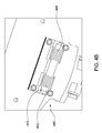
- FIG. 4A , 4B , 4C , and 4D illustrate a leveling ring of the spider according to one embodiment of the invention.
- FIG. 5A illustrates the spider in a setback position according to one embodiment of the invention.
- FIG. 5B illustrates the spider in a set position according to one embodiment of the invention.
- FIG. 6 illustrates a control line guide assembly of the spider according to one embodiment of the invention.
- FIG. 7A , 7B , 7C , and 7D illustrate operation of the spider according to one embodiment of the invention.
- FIG. 1A illustrates a gripping apparatus 100 according to one embodiment of the invention.
- the gripping apparatus 100 comprises a spider 100 that may be flush mountable and disposable within a rotary table (not shown).
- the spider 100 includes a cover assembly 10 coupled to a housing 200 for housing a slip assembly 300 (shown in FIG. 3 ), a leveling ring 400, and a control line guide assembly 600, and a control line support 650.
- the control line support 650 includes a plurality of rollers disposed along a track.
- the cover assembly 10 is attached to the top of the housing 200, such as with bolts, and includes an opening disposed through the center that coincides with the center of the housing 200 for receiving tubulars.
- the cover assembly 10 may comprise two separate sections to allow the housing 200 to open and close without removing the cover assembly 10.
- the cover assembly 10 may be used to protect the internal assemblies of the spider 100.
- FIG. 1B illustrates the gripping apparatus 100 with the cover assembly 10 removed from the housing 200.
- slip assembly 300 is disposed within and surrounded by the housing 200.
- the slip assembly 300 is operable between a set and setback position for gripping and releasing a tubular located though the center of the spider 100.
- the leveling ring 400 is coupled to the slip assembly 300 and is movable in a vertical direction, via a piston/cylinder arrangement for example, to actuate the slip assembly 300.
- the control line guide assembly 600 which may be used to protect and retain control lines that are raised from and/or lowered into a wellbore along with a tubular.
- the control line guide assembly 600 is operable between an open and closed position to allow the introduction and removal of the control lines, as subsequent tubulars are run through the spider 100. In this manner, the control lines may be protected from being damaged, such as by being crimped or pinched by the slip assembly 300, as the spider 100 grips and releases engagement with tubulars.
- FIGS. 2A and 2B illustrate a body 210 and a door 220, respectively, of the housing 200.
- the spider 100 is formed by pivotally coupling the body 210 and the door 220 using one or more connectors 215 and 225, such as hinges, formed on both sides of the body 210 and the door 220, respectively.
- the body 210 and the door 220 may be hinged on one side and selectively locked together on the other side.
- the housing 200 includes a bowl 240 that extends vertically through a lower portion of the body 210 and the door 220 to house the slip assembly 300.
- the housing 200 includes a flange 230 formed on an upper portion of the body 210 and the door 220 for connection to the cover assembly 10 and for mounting the spider 100 in a rotary table.
- Other ways of mounting the spider 100 in the rotary table and of connecting the cover assembly 10 are also contemplated.
- the spider 100 may also be secured within the rotary table to prevent relative rotation between the spider and the rotary table, such as with one or more key/slot arrangements.
- One or more connectors 215 are formed on each side of the body 210 and one or more connectors 225 are formed on each side of the door 220.
- a gap 217 exists between each connector 215 for mating with the connectors 225 formed on the door 220.
- a hole 219 is formed through each connector 215 and 225 to accommodate a pin. The holes 219 of the connectors 215 and 225 are aligned so that the pin may be disposed through the holes 219 to secure the body 210 to the door 220.
- the interior of the bowl 240 may include a control line recess 241 located adjacent an actuator slot 242, and shoulders 243 radially extending from the inner surface of the bowl 240.
- the control line recess 241 is adapted to receive control lines that are being raised and/or lowered with a tubular and to protect the control lines as the tubular is being supported by the spider 100.
- the actuator slot 242 is located adjacent the control line recess 241 and is adapted to house an actuator (shown in FIG. 6 ) that is operable to open and close communication with the control line recess 241.
- the bowl 240 includes three sets of shoulders 243, two sets on the body 210 and one set on the door 220, each set having three shoulders spaced apart vertically.
- Each shoulder 243 may include an angled top surface 245 and an angled side surface 249 along which the slip assembly 300 may travel into a set and a setback position.
- the shoulders 243 are positioned to place the slip assembly 300 further away from the center of the spider 100, thereby creating a larger inner diameter to accommodate larger sized pipes.
- the shoulders 243 are positioned to place the slip assembly 300 closer to the center of the spider 100, thereby creating a smaller inner diameter to accommodate smaller sized pipes.
- the uppermost shoulder 243 of each set may include a slot 247 for guiding the axial movement of the slip assembly 300 along the shoulder 243.
- the slots 247 may mate with a key formed on the outer surface of the slip assembly 300 to maintain the path of the moving slip assembly 300 and prevent the slip assembly 300 from rotating relative to the housing 200. Because the slip assembly 300 cannot rotate within the housing 200 and the housing 200 may be rotatively secured within the rotary table, the spider 100 may be used to apply a back up torque during the make up or break out of tubular connections.
- FIGS. 3A-3C illustrate the slip assembly 300.
- the slip assembly 300 includes a slip body 310 adapted to retain a plurality of gripping elements 335 (as shown in FIG. 3C ), such as dies, and includes a slip bracket 350.
- the slip body 310 includes a slot 320, slip retainers 330, and shoulders 340.
- the slot 320 is disposed in the top portion of the slip body 310 and includes an open end adapted to receive the slip bracket 350.
- the slot 320 may also include a dovetail groove or inwardly tapering sidewalls, such that upon horizontal insertion of the slip bracket 350 into the open end of the slot 320, the slip bracket 350 is prevented from being vertically displaced relative to the slip body 310.
- the slip retainers 330 include slots along the slip body 310, opposite the shoulders 340, which are adapted to receive and retain the gripping elements 335 to the slip body 310.
- the gripping elements 335 may be secured in the slip retainers 330 using a retainer 336 bolted to the slip body 310 above the gripping elements (as shown in FIG. 3C ). In this manner, the dies are removable and easily replaceable from the slip body 310.
- the gripping elements 335 rest on horizontal load bearing plates to evenly distribute any load received by the gripping elements 335 and to prevent stress concentrations on the slip body 310.
- the slip assembly 300 also includes three shoulders 340 adapted to mate with one set of the shoulders 243 of the housing 200. Specifically, each shoulder 340 includes an angled bottom surface 345 and an angled side surface 349, operable to engage the top surfaces 245 and side surfaces 249, respectively, of the housing 200 to facilitate movement of the slip assembly 300 within the spider 100.
- FIG. 3B illustrates the slip bracket 350, which couples the slip assembly 300 to the leveling ring 400.
- the slip bracket 350 includes a base 353, which is received into the slot 320, a pair of supports 355 having a channel 359 disposed therebetween, and openings 357 disposed through the supports 355 for securing the slip bracket 350 to the leveling ring 400. Openings 351 may also be located in the base 353 to retain the slip bracket 350 in the slot 320 using pins or bolts (as shown in FIG 3C ).
- the channel 359 includes an angled surface adapted to engage a corresponding surface on the leveling ring 400, as further described below, along which the leveling ring 400 may slide to transmit a force to actuate the slip assembly 300.
- three slip assemblies 300 are disposed in the housing 200 and uniformly coupled to the leveling ring 400.
- each slip assembly 300 is individually replaceable.
- the slip bracket 350 may be formed as an integral part of the slip assembly 300, such as integral with the slip body 310.
- FIG. 4A illustrates a displacement member, such as the leveling ring 400 for connecting multiple slip assemblies 300 and synchronizing their movement.
- the leveling ring 400 includes a ring body 410 having an opening disposed through the center of the body that coincides with the center of the spider 100, and a gap 411 that coincides with the control line recess 241 in the housing 200 to provide the control lines unhindered access to the control line recess 241.
- One or more retention assemblies 420 (further shown in FIG. 4D ) of the leveling ring 400 extend through the ring body 410 for housing and securing another displacement member, such as a rod 429 to the ring body 410 that is used to raise and lower the leveling ring 400 via a piston/cylinder arrangement for example.
- the leveling ring 400 also includes guides 430 that may be used to direct the vertical movement of the leveling ring 400 and prevent the leveling ring 400 from rotating relative to the housing 200.
- the guides 430 may be spaced apart around the circumference of the ring body 410.
- the leveling ring 400 further includes one or more spring assemblies 440 housed in the ring body 410, as illustrated in FIG. 4B , for helping retain the slip assembly 300 in a setback position.
- Each spring assembly 440 includes a spring rod 443 secured in the ring body 410 and one or more biasing members, such as torsion springs 445 disposed around the spring rod 443.
- each torsion spring 445 includes an end portion that extends around a mating member 447, such as a slip pin 447 that couples the slip assembly 300 to the leveling ring 400.
- the slip pin 447 is disposed through the supports 355 of the slip bracket 350 and a slot 419 a guide member 415 extending from the ring body 410, which is received between the supports 355 and along the channel 359 of the slip bracket 350, thereby coupling the ring body 410 to the slip body 310.
- the torsion springs 445 provide a constant positive force to the slip pin 447, forcing the slip pin 447 in one direction along the slot 419 of the guide member 415, thereby facilitating movement of the slip assembly 300 via the slip bracket 350 to the setback position.
- the guide member 415 may project from a recess formed in the bottom of the ring body 410 and may include an angled bottom surface from the center of the leveling ring 400 to its outer diameter.
- the guide member 415 may be operable to engage the channel 359 of the slip bracket 350 and may be disposed between the supports 355 of the slip bracket 350 when coupled to the slip bracket 350 by the slip pin 447.
- the bottom surface of the guide member 415 may be angled to correspond with the channel 359 of the slip bracket 350.
- the slot 419 in the guide member 415 may also be angled generally extending from the center of the leveling ring 400 to its outer diameter within the guide member 415.
- the slip pin 447 travels along the slot 419 of the guide member 415 when the leveling ring 400 is actuated to move the slip assembly 300 via the slip bracket 350.
- the engagement between the slip bracket 350 and the guide member 415 may provide the spider 100 with a large slip assembly 300 setback.
- the engagement between the slip bracket 350 and the guide member 415 allows the spider 100 to handle a large range of tubular diameters, including relatively larger diameter tubulars, using the large slip assembly 300 setback, without any significant increase in the height of the tool.
- the spider 100 is configured to fit within a standard rotary table, such as a 37-1/2 inch rotary table that is disposed in a rig floor, while remaining substantially flush with the surface of the rig floor.
- the guide member 415 may be formed as a part of or attached to the slip assembly 300.
- the guide member 415 may have a slot 419 along which a pin 447 of the leveling ring 400 travels to radially displace the slip assembly 300.
- the slip assembly 300 is radially displaced to provide a large set back of the slip assembly 300, as discussed herein.
- FIG. 4D illustrates a cross sectional view of the retention assembly 420.
- One or more retention assemblies 420 may be spaced apart around the circumference of the ring body 410 (as shown in FIG. 4A ).
- Each retention assembly 420 includes a rod connection 421, for example a nut and pin, a retention cap 423 coupled to the ring body 410 to retain a bearing assembly 425 within the ring body 410, and lubrication paths 427 for providing a lubrication fluid to the bearing assembly 425.
- the rod connection 421 may be used to couple the rod 429, which is disposed through the ring body 410 and the bearing assembly 425, to the ring body 410 and retain the rod 429 within the bearing assembly 425.
- the rod 429 is actuated a vertical direction, by a piston/cylinder arrangement for example, the ring body 410 is moved along with the rod 429 via the retention assembly 420 to actuate the slip assembly 300 in the set and setback positions.
- the bearing assembly 425 surrounds the rod 429 and is located within the ring body 410, and is further in communication with the lubrication paths 427, such that a lubrication fluid may be supplied to the bearing assembly 425 to lubrication the retention assembly 420.
- the bearing assembly 425 may include an outer housing and a bearing that is rotatably mounted within the housing.
- the rod 429 may tilt relative to a horizontal axis of the ring body 410 using the bearing.
- the ring body 410 may be substantially uniformly moved in the vertical direction by use of the bearing assembly 425, which may compensate for any non-uniform vertical movement of the one or more rods 429 when directing the leveling ring 400 or the leveling ring 400 when directing the slip assembly 300.
- FIG. 5A illustrates a cross sectional view of the spider 100 in the setback position, located in the housing 200.
- the leveling ring 400 is raised to about an uppermost point via the one or more rods 429.
- the slip pin 447 is directed along and laterally displaced to the lower end of the slot 419 in the guide member 415 of the ring body 410, thereby laterally displacing the slip bracket 350 and retracting the slip assembly 300 to the setback position.
- the bottom surface of the guide member 415 of the ring body 410 may also engage the channel 359 of the slip bracket 350 to facilitate lateral movement of the slip bracket 350 relative to the leveling ring 400.
- Assisting the movement of the slip pin 447 in this direction is the torsion spring 445, as described above, which is disposed around the spring rod 443 at one end and provides a positive force on the slip pin 447 to facilitate setting back of the slip assembly 300.
- the shoulders 340 of the slip assembly 300 engage and slide along the shoulders 243 of the housing 200. Specifically, starting from the set position, the side surfaces 349 of the shoulders 340 engage and slide up the side surfaces 249 of the corresponding shoulders 243 of the housing 200 until they reach the top surfaces 245.
- the contours of the shoulders 340 of the slip assembly 300 correspond with the contours of the shoulder 243 of the housing 200 to allow substantial retraction of the slip assembly 300 from the center of the spider 100, such as from engagement with the tubular 15. This function helps increase the range of tubular sizes that the spider 100 may be used to grip and release.
- the angle of the bottom surfaces 345 of the slip assembly 300 is substantially equal to the angle of the top surfaces 245 of the housing 200. In one embodiment, the angle of the bottom surface 345 may vary between each shoulder 340. In one embodiment, the angle of the top surface 245 may vary between each shoulder 243. In one embodiment, the angle of the slot 419 of the leveling ring 400 is substantially equal to the angle of the bottom surface 345 of the slip assembly 300.
- the angle of the slot 419 of the leveling ring 400 is substantially equal to the angle of the top surfaces 245 of the shoulders 243.
- the angle of the slot 419, the bottom surfaces 345 of the slip assembly, and/or the top surfaces of the shoulders 243 may include a range of about 40 degrees to about 50 degrees, a range of about 30 degrees to about 60 degrees, and/or a range of about 20 degrees to about 80 degrees.
- the slip assembly 300 is operable to travel a distance of about 5 inches from the setback position to the fully extended position.
- Each slip assembly 300 includes a setback distance of about 5 inches relative to the center of the spider 100, thereby providing a total setback distance of about 10 inches using opposing slip assemblies 300.
- the leveling ring 400 is coupled to each slip assembly 300 (as described herein) to allow a greater lateral or horizontal displacement of each slip assembly 300 relative to the longitudinal or vertical displacement of the leveling ring 400.
- the spider 100 includes three slip assemblies 300 that are operable to provide a ten inch setback within the spider 100 to accommodate numerous tubular sizes having control lines clamped to the tubular, as well as other assorted downhole equipment.
- the spider 100 is operable to provide about a 10 inch setback, while maintaining a total tool height of no more than about 37 inches. In one embodiment, the spider 100 is operable to provide about a 10 inch setback and is configurable within a 37-1 ⁇ 2 inch rotary table.
- FIG. 5B illustrates a cross sectional view of the spider 100 in the set position, located in the housing 200.
- the leveling ring 400 is lowered to about a lowermost point via the one or more rods 429.
- the slip pin 447 is directed along and laterally displaced to the upper end of the slot 419 in the guide member 415 of the ring body 410, thereby laterally displacing the slip bracket 350 and projecting the slip assembly 300 radially outwardly to the set position.
- the bottom surface of the guide member 415 of the ring body 410 may slide along the surface of the channel 359 of the slip bracket 350 to transfer the load between the leveling ring 400 and the slip assembly 300.
- the torsion spring 445 Resisting the movement of the slip pin 447 in this direction is the torsion spring 445, as described above, which is disposed around the spring rod 443 at one end and provides a positive force on the slip pin 447 to facilitate setting back of the slip assembly 300.
- the shoulders 340 of the slip assembly 300 slide down along the shoulders 243 of the bowl 240 of the housing 200.
- the bottom surfaces 345 of the slip assembly 300 travel down the top surfaces 245 of the housing 200.
- the shoulders 340 of the slip assembly 300 drop off of the top surfaces 245, thereby allowing the side surfaces 349 and 249 of the slip assembly 300 and the housing 200 to engage to further project the slip assembly 300 outwardly into the set position.
- the side surfaces 349 of the shoulder 340 travel down along the side surfaces 249 of the shoulder 243. This additional engagement further helps increase the range of tubular sizes that the spider 100 may be used to grip and release.
- the gripping elements 335, or dies engage and grip the tubular 15 disposed through the spider 100.
- only the side surface 349 of the uppermost shoulder 340 of the slip assembly 300 contacts the side surface 249 of the uppermost shoulder 243 of the housing 200 to facilitate projection of the of slip assembly 300 into the set position.
- the angle of the side surfaces 349 of the slip assembly 300 is substantially equal to the angle of the side surfaces 249 of the housing.
- the angle of the side surfaces 345 may vary between each shoulder 340.
- the angle of the top surfaces 245 may vary between each shoulder 243.
- FIG. 6 illustrates a cross sectional view of the control line guide assembly 600 in the housing 200.
- the control line guide assembly 600 includes an actuator 610 disposed in the actuator slot 242 of the housing 200, a door 630 disposed around the control line recess 241 of the housing 200, a retention plate 637 for securing the door 630 around the control line recess 241 and the actuator 610 in the actuator slot 242, and a gear arrangement 620 coupled to the actuator 610 and the door 630.
- the actuator 610 comprises an electrical, mechanical, hydraulic, and/or any other type of actuator known to one of ordinary skill to provide actuation of the door 630.
- the door 630 may include a half cylindrical segment having a lip disposed at its lower end (illustrated at the lower right hand side of the partial cross section of the door 630) adapted to seat in a corresponding groove in the housing 200 to retain the door 630 around the control line recess 241 and in the housing 200.
- the door 630 is rotatable relative to the control line recess 241 to an open and closed position, to allow and prevent access to the control line recess 241. When in the open position, control lines may be introduced into the control line recess 241, away from the slip assembly 300.
- the door 630 may be closed to retain the control lines in the control line recess 241 and protect the control lines from damage that may be caused by the actuation of the slip assembly 300.
- the actuator 610 is operable to actuate the door 630 into the open and closed positions via the gear arrangement 620.
- the gear arrangement 620 may include a gear track disposed on the outer surface of the door 630 that interlocks with a stationary spur gear coupled to the actuator 610.
- the actuator 610 may rotate the spur gear in a first direction, thereby rotating the door 630 into a first position, such as the open position, via the gear track.
- the actuator 610 may then rotate the spur gear in an opposite direction, thereby rotating the door 630 into a second position, such as the closed position, via the gear track.
- the slip assembly 300 may communicate with the control line guide assembly 600 in a manner that the slip assembly 300 may not operate if the door 630 of the control line guide assembly 600 is in the open position or any other intermediate position between the open and closed positions.
- a control lock may be provided on the door 630 of the control line guide assembly 600 to prevent actuation of the slip assembly 600 when the door 630 is located in any particular position.
- the spider 100 may include sensors operable to determine the relative position of door 630 of the control line guide assembly 600, the leveling ring 400, and/or the slip assembly 300.
- the sensors may also be operable to communicate these positions to facilitate the operation of the control line guide assembly 600, the leveling ring 400, and/or the slip assembly 300 to prevent premature activation of the control line guide assembly 600, the leveling ring 400, and/or the slip assembly 300 and to ensure efficient operation of the spider 100.
- a sensor may be used to determine whether the door 630 of the control line guide assembly 600 is in the closed position, and such determination may be use to either allow or prevent the slip assembly 300 from activation.
- FIGS. 7A-7D illustrate operation of the spider according to one embodiment.
- the spider 100 is flush mounted in a rotary table.
- the slip assembly 300 is in the retracted or setback position in the housing 200 and the control line guide assembly 600, specifically the door 630, is in the open position to receive a control line.
- a tubular 700 and a control line 750, such as an umbilical, are introduced through the spider 100.
- the control line 750 is directed to the control line recess 241 in the housing 200, either manually or by using an automated device, such as a mechanical arm disposed adjacent the spider 100.
- the control line support 650 may be used to support and guide the control line 750 through the spider 100 as it is introduced into or retrieved from a wellbore.
- the actuator 610 is actuated to close the door 630 to retain the control line 750 away from the slip assembly 300 and prevent the control line 750 from exiting the control line recess 241.
- a piston/cylinder arrangement may be used to actuate and set the slip assembly 300 into engagement with the tubular 700 as described above.
- a make up/break out operation may be performed.
- the piston/cylinder arrangement may be actuated to retract or setback the slip assembly 300, thereby causing the slip assembly 300 to move radially away from the tubular 700.
- the control line guide assembly 600 may be actuated to the open position to release the control line 750.
- one or more piston/cylinder arrangements may be coupled to one or more rods 429 to move the leveling ring 400 and actuate the slip assembly 300.
- one or more rods 429 may be actuated using electrical, mechanical, and/or hydraulic force.
- the overall height of the spider 100 may be about 3 feet. In one embodiment, the spider 100 may be adapted to fit within a 37-1/2 inch rotary table.
- a gripping apparatus for supporting a tubular.
- the gripping apparatus may include a housing, a slip assembly disposed in the housing, and a leveling ring operable to move the slip assembly in the housing.
- the gripping apparatus may further include a guide member and a mating member operable to couple the slip assembly to the leveling ring. The longitudinal movement of the leveling ring directs the mating member along the guide member to radially displace the slip assembly relative to the housing.
- the guide member may comprise a portion of the leveling ring that projects from a bottom surface of the leveling ring. In one embodiment, the guide member may comprise a slot along which the mating member is directed. In one embodiment, the mating member may be a slip pin. In one embodiment, the slip assembly may comprise a slip bracket coupled to the guide member using the mating member. In one embodiment, the leveling ring may comprise a biasing member coupled to the mating member to provide a constant force on the mating member in one direction. In one embodiment, the guide member may comprise an angled slot and the mating member may comprise a pin, and downward movement of the leveling ring moves the pin up the angled slot. Upward movement of the leveling ring moves the pin down the angled slot.
- the slip assembly when the leveling ring is lowered relative to the housing, the slip assembly is radially projected toward a center of the housing. When the leveling ring is raised relative to the housing, the slip assembly is radially retracted from a center of the housing.
- the housing may comprise a shoulder projecting from an inner surface of the housing and the slip assembly may comprise a shoulder movable along the shoulder of the housing. Longitudinal movement of the leveling ring moves the shoulder of the slip assembly along the shoulder of the housing.
- one or more rods may be coupled to the leveling ring to move the leveling ring in the longitudinal direction.
- a control line guide assembly may be disposed in the housing and operable to retain control lines from engagement with the slip assembly.
- a sensor may be operable determine a position of the control line guide assembly and further operable to communicate the position to facilitate operation of the slip assembly.
- a gripping apparatus for supporting a tubular.
- the gripping apparatus may comprise a housing, a slip assembly disposed in the housing and having a slip bracket to radially project and retract the slip assembly relative to the housing, and a leveling ring having a slot and a pin.
- the pin is disposed through the slot and the slip bracket, and vertical displacement of the leveling ring moves the pin along the slot and thereby moves the slip bracket to radially project and retract the slip assembly relative to the housing.
- a control line guide assembly may be disposed in the housing adjacent the slip assembly and operable to retain control lines from engagement with the slip assembly.
- a sensor may be operable to determine a position of the control line guide assembly and further operable to communicate the position to facilitate operation of the slip assembly.
- a gripping apparatus for supporting a tubular.
- the gripping apparatus may comprise a housing, a slip assembly disposed in the housing and having a slip bracket, and a displacement member coupled to the slip bracket. Longitudinal displacement of the displacement member relative to the housing allows the slip bracket to move the slip assembly a lateral distance that is greater than the longitudinal displacement of the displacement member.
- the housing may comprise a shoulder having an incline along which the slip assembly travels, and a ratio of a lateral length and a vertical height defined by the incline may be less than a ratio defined by the lateral distance that the slip assembly moves and the longitudinal displacement that the displacement member moves.
- the displacement member may comprise at least one of a leveling ring, a rod, and a combination thereof.
- a method for supporting a tubular using a gripping apparatus may comprise providing the tubular through the gripping apparatus.
- the gripping apparatus may include a housing, a slip assembly disposed in the housing, and a leveling ring operable to actuate the slip assembly.
- the method may include actuating the leveling ring to actuate the slip assembly, wherein a longitudinal displacement of the leveling ring relative to the housing allows the slip assembly to move a lateral distance that is greater than the longitudinal displacement of the leveling ring; and engaging the tubular using the slip assembly.
- the housing may comprise a shoulder having an incline along which the slip assembly travels, and a ratio of a lateral length and a vertical height defined by the incline may be less than a ratio defined by the lateral distance that the slip assembly moves and the longitudinal displacement that the leveling ring moves.
Landscapes
- Engineering & Computer Science (AREA)
- Geology (AREA)
- Life Sciences & Earth Sciences (AREA)
- Mining & Mineral Resources (AREA)
- Physics & Mathematics (AREA)
- Environmental & Geological Engineering (AREA)
- Fluid Mechanics (AREA)
- Mechanical Engineering (AREA)
- General Life Sciences & Earth Sciences (AREA)
- Geochemistry & Mineralogy (AREA)
- Earth Drilling (AREA)
- Moulds For Moulding Plastics Or The Like (AREA)
- Automatic Assembly (AREA)
- Clamps And Clips (AREA)
Abstract

Description
- Embodiments of the invention generally relate to a gripping apparatus for supporting tubulars. In particular, embodiments of the invention relate to a gripping apparatus disposable within a rotary table and having a slip assembly for gripping tubulars that is operable using a leveling ring. Additional embodiments of the invention relate to a control line guide assembly for protecting control lines in use with the supported tubulars.
- The handling of pipe strings has traditionally been performed with the aid of a spider. Typically, spiders include a plurality of slips circumferentially surrounding the exterior of the pipe string. The slips are housed in what is commonly referred to as a "bowl." The bowl is regarded to be the surfaces on the inner bore of the spider. The inner sides of the slips usually carry teeth formed on hard metal dies for engaging the pipe string. The exterior surface of the slips and the interior surface of the bowl have opposing engaging surfaces which are inclined and downwardly converging. The inclined surfaces allow the slips to move vertically and radially relative to the bowl. In effect, the inclined surfaces serve as camming surfaces for engaging the slips with the pipe. Thus, when the weight of the pipe is transferred to the slips, the slips will move downwardly with respect to the bowl. As the slips move downward along the inclined surfaces, the inclined surfaces urge the slips to move radially inward to engage the pipe. In this respect, this feature of the spider is referred to as "self tightening." Further, the slips are designed to prohibit release of the pipe string until the pipe load is supported by another means.
- Traditionally, a spider is located above a rotary table situated in the rig floor. More recently, flush mounted spiders have been developed so that the spider does not intrude upon the work deck above the rotary. Because flush mounted spiders reside within the rotary table, the pipe size handling capacity of the spider is limited by the size of the rotary table. Current spider designs further augment the problem of limited pipe size handling capacity. Thus, in order to handle a larger pipe size, a larger rotary table must be used. However, the process of replacing the existing rotary table is generally economically impractical.
- This pipe size handling capacity problem has been further complicated with the advent of intelligent completion systems. Improvements in technology now allow wellbores to be equipped with sensors, gauges, and other electronic devices that can be used to monitor various wellbore characteristics such as temperature, pressure, flow rate, etc. Additionally, downhole tools can be controlled remotely from the well surface or at some other remote location. However, to communicate with such devices and tools, these intelligent systems require multiple control lines that are run from the well surface to these downhole components with the pipe string. Accommodations must be made to make sure that these control lines are not pinched or damaged by the setting of the slips during makeup or breakup of the pipe string.
- Another problem of some spiders currently in use is that many pipe joints may include coatings, for example to prevent corrosion, requiring higher downward forces to ensure positive slip engagement with the pipe joints. Further, in many completion operations the maximum height of the spider is limited by a connection height due to the length of the pipe joints. Further still, the slips are generally held in position in the bowl by friction, resulting in a limited amount of torque that may be applied to the pipe joints before slippage occurs between the slips and the bowl.
- There is a need, therefore, for an improved gripping apparatus to address and overcome the problems described above.
- In accordance with one aspect of the present invention, there is provided a gripping apparatus for supporting a tubular. The gripping apparatus may include a housing, a slip assembly disposed in the housing, and a leveling ring operable to move the slip assembly in the housing. The gripping apparatus may further include a guide member and a mating member operable to couple the slip assembly to the leveling ring. The longitudinal movement of the leveling ring directs the mating member along the guide member to radially displace the slip assembly relative to the housing.
- In accordance with another aspect of the present invention, there is provided a gripping apparatus for supporting a tubular. The gripping apparatus may have a housing and a slip assembly disposed in the housing. The slip assembly may include a slip bracket that is used to radially project and retract the slip assembly relative to the housing. The gripping apparatus may include a leveling ring having a slot and a pin. The pin is disposed through the slot and the slip bracket so that vertical displacement of the leveling ring moves the pin along the slot, thereby moving the slip bracket to radially project and retract the slip assembly relative to the housing.
- Embodiments of the invention relate to a gripping apparatus for supporting a tubular. The gripping apparatus may comprise a housing and a slip assembly disposed in the housing that includes a slip bracket. The gripping apparatus may further include a displacement member coupled to the slip bracket. A longitudinal displacement of the displacement member relative to the housing allows the slip bracket to move the slip assembly a lateral distance that is greater than the longitudinal displacement of the displacement member.
- In one embodiment, the housing comprises a shoulder having an incline along which the slip assembly travels. A ratio of a lateral length and a vertical height defined by the incline is less than a ratio defined by the lateral distance that the slip assembly moves and the longitudinal displacement that the displacement member moves.
- In accordance with further aspect of the present invention, there is provided a method for supporting a tubular using a gripping apparatus. The method may comprise the step of providing the tubular through the gripping apparatus. The gripping apparatus includes a housing, a slip assembly disposed in the housing, and a leveling ring operable to actuate the slip assembly. The method may further comprise the step of actuating the leveling ring to actuate the slip assembly, wherein a longitudinal displacement of the leveling ring relative to the housing allows the slip assembly to move a lateral distance that is greater than the longitudinal displacement of the leveling ring. The method may further comprise the step of engaging the tubular using the slip assembly.
- In one embodiment, the housing comprises a shoulder having an incline along which the slip assembly travels. A ratio of a lateral length and a vertical height defined by the incline is less than a ratio defined by the lateral distance that the slip assembly moves and the longitudinal displacement that the displacement member moves.
- Further aspects and preferred features are set out in claim 2 et seq.
- So that the manner in which the above recited features of the invention can be understood in detail, a more particular description of the invention, briefly summarized above, may be had by reference to embodiments, some of which are illustrated in the appended drawings. It is to be noted, however, that the appended drawings illustrate only typical embodiments of this invention and are therefore not to be considered limiting of its scope, for the invention may admit to other equally effective embodiments.
-
FIG. 1A illustrates a spider according to one embodiment of the invention. -
FIG. 1B illustrates the internal assemblies of the spider according to one embodiment of the invention. -
FIG. 2A and 2B illustrate a housing of the spider according to one embodiment of the invention. -
FIG. 3A ,3B , and3C illustrate a slip assembly of the spider according to one embodiment of the invention. -
FIG. 4A ,4B ,4C , and4D illustrate a leveling ring of the spider according to one embodiment of the invention. -
FIG. 5A illustrates the spider in a setback position according to one embodiment of the invention. -
FIG. 5B illustrates the spider in a set position according to one embodiment of the invention. -
FIG. 6 illustrates a control line guide assembly of the spider according to one embodiment of the invention. -
FIG. 7A ,7B ,7C , and7D illustrate operation of the spider according to one embodiment of the invention. -
FIG. 1A illustrates agripping apparatus 100 according to one embodiment of the invention. As illustrated, thegripping apparatus 100 comprises aspider 100 that may be flush mountable and disposable within a rotary table (not shown). Thespider 100 includes acover assembly 10 coupled to ahousing 200 for housing a slip assembly 300 (shown inFIG. 3 ), a levelingring 400, and a controlline guide assembly 600, and acontrol line support 650. In one embodiment, thecontrol line support 650 includes a plurality of rollers disposed along a track. - As shown, the
cover assembly 10 is attached to the top of thehousing 200, such as with bolts, and includes an opening disposed through the center that coincides with the center of thehousing 200 for receiving tubulars. Thecover assembly 10 may comprise two separate sections to allow thehousing 200 to open and close without removing thecover assembly 10. Thecover assembly 10 may be used to protect the internal assemblies of thespider 100. -
FIG. 1B illustrates thegripping apparatus 100 with thecover assembly 10 removed from thehousing 200. As illustrated,slip assembly 300 is disposed within and surrounded by thehousing 200. Theslip assembly 300 is operable between a set and setback position for gripping and releasing a tubular located though the center of thespider 100. To actuate theslip assembly 300, the levelingring 400 is coupled to theslip assembly 300 and is movable in a vertical direction, via a piston/cylinder arrangement for example, to actuate theslip assembly 300. Also disposed through thehousing 200 and located adjacent the slip assembly is the controlline guide assembly 600, which may be used to protect and retain control lines that are raised from and/or lowered into a wellbore along with a tubular. The controlline guide assembly 600 is operable between an open and closed position to allow the introduction and removal of the control lines, as subsequent tubulars are run through thespider 100. In this manner, the control lines may be protected from being damaged, such as by being crimped or pinched by theslip assembly 300, as thespider 100 grips and releases engagement with tubulars. -
FIGS. 2A and 2B illustrate abody 210 and adoor 220, respectively, of thehousing 200. Thespider 100 is formed by pivotally coupling thebody 210 and thedoor 220 using one ormore connectors body 210 and thedoor 220, respectively. In an alternative embodiment, thebody 210 and thedoor 220 may be hinged on one side and selectively locked together on the other side. Thehousing 200 includes abowl 240 that extends vertically through a lower portion of thebody 210 and thedoor 220 to house theslip assembly 300. - The
housing 200 includes aflange 230 formed on an upper portion of thebody 210 and thedoor 220 for connection to thecover assembly 10 and for mounting thespider 100 in a rotary table. Other ways of mounting thespider 100 in the rotary table and of connecting thecover assembly 10 are also contemplated. It is further contemplated that thespider 100 may also be secured within the rotary table to prevent relative rotation between the spider and the rotary table, such as with one or more key/slot arrangements. One ormore connectors 215 are formed on each side of thebody 210 and one ormore connectors 225 are formed on each side of thedoor 220. Agap 217 exists between eachconnector 215 for mating with theconnectors 225 formed on thedoor 220. Ahole 219 is formed through eachconnector holes 219 of theconnectors holes 219 to secure thebody 210 to thedoor 220. - The interior of the
bowl 240 may include acontrol line recess 241 located adjacent anactuator slot 242, and shoulders 243 radially extending from the inner surface of thebowl 240. Thecontrol line recess 241 is adapted to receive control lines that are being raised and/or lowered with a tubular and to protect the control lines as the tubular is being supported by thespider 100. Theactuator slot 242 is located adjacent thecontrol line recess 241 and is adapted to house an actuator (shown inFIG. 6 ) that is operable to open and close communication with thecontrol line recess 241. - As illustrated, the
bowl 240 includes three sets ofshoulders 243, two sets on thebody 210 and one set on thedoor 220, each set having three shoulders spaced apart vertically. Eachshoulder 243 may include an angledtop surface 245 and anangled side surface 249 along which theslip assembly 300 may travel into a set and a setback position. Theshoulders 243 are positioned to place theslip assembly 300 further away from the center of thespider 100, thereby creating a larger inner diameter to accommodate larger sized pipes. In addition, theshoulders 243 are positioned to place theslip assembly 300 closer to the center of thespider 100, thereby creating a smaller inner diameter to accommodate smaller sized pipes. - In another aspect, the
uppermost shoulder 243 of each set may include aslot 247 for guiding the axial movement of theslip assembly 300 along theshoulder 243. Theslots 247 may mate with a key formed on the outer surface of theslip assembly 300 to maintain the path of the movingslip assembly 300 and prevent theslip assembly 300 from rotating relative to thehousing 200. Because theslip assembly 300 cannot rotate within thehousing 200 and thehousing 200 may be rotatively secured within the rotary table, thespider 100 may be used to apply a back up torque during the make up or break out of tubular connections. -
FIGS. 3A-3C illustrate theslip assembly 300. Theslip assembly 300 includes aslip body 310 adapted to retain a plurality of gripping elements 335 (as shown inFIG. 3C ), such as dies, and includes aslip bracket 350. Theslip body 310 includes aslot 320, slipretainers 330, and shoulders 340. Theslot 320 is disposed in the top portion of theslip body 310 and includes an open end adapted to receive theslip bracket 350. Theslot 320 may also include a dovetail groove or inwardly tapering sidewalls, such that upon horizontal insertion of theslip bracket 350 into the open end of theslot 320, theslip bracket 350 is prevented from being vertically displaced relative to theslip body 310. Theslip retainers 330 include slots along theslip body 310, opposite theshoulders 340, which are adapted to receive and retain thegripping elements 335 to theslip body 310. Thegripping elements 335 may be secured in theslip retainers 330 using aretainer 336 bolted to theslip body 310 above the gripping elements (as shown inFIG. 3C ). In this manner, the dies are removable and easily replaceable from theslip body 310. Thegripping elements 335 rest on horizontal load bearing plates to evenly distribute any load received by thegripping elements 335 and to prevent stress concentrations on theslip body 310. As shown in this embodiment, theslip assembly 300 also includes threeshoulders 340 adapted to mate with one set of theshoulders 243 of thehousing 200. Specifically, eachshoulder 340 includes anangled bottom surface 345 and anangled side surface 349, operable to engage thetop surfaces 245 andside surfaces 249, respectively, of thehousing 200 to facilitate movement of theslip assembly 300 within thespider 100. -
FIG. 3B illustrates theslip bracket 350, which couples theslip assembly 300 to theleveling ring 400. Theslip bracket 350 includes abase 353, which is received into theslot 320, a pair ofsupports 355 having achannel 359 disposed therebetween, andopenings 357 disposed through thesupports 355 for securing theslip bracket 350 to theleveling ring 400.Openings 351 may also be located in the base 353 to retain theslip bracket 350 in theslot 320 using pins or bolts (as shown inFIG 3C ). Thechannel 359 includes an angled surface adapted to engage a corresponding surface on theleveling ring 400, as further described below, along which theleveling ring 400 may slide to transmit a force to actuate theslip assembly 300. - In one embodiment, three
slip assemblies 300 are disposed in thehousing 200 and uniformly coupled to theleveling ring 400. In one embodiment, eachslip assembly 300 is individually replaceable. In one embodiment, theslip bracket 350 may be formed as an integral part of theslip assembly 300, such as integral with theslip body 310. -
FIG. 4A illustrates a displacement member, such as the levelingring 400 for connectingmultiple slip assemblies 300 and synchronizing their movement. The levelingring 400 includes aring body 410 having an opening disposed through the center of the body that coincides with the center of thespider 100, and agap 411 that coincides with thecontrol line recess 241 in thehousing 200 to provide the control lines unhindered access to thecontrol line recess 241. One or more retention assemblies 420 (further shown inFIG. 4D ) of the levelingring 400 extend through thering body 410 for housing and securing another displacement member, such as arod 429 to thering body 410 that is used to raise and lower theleveling ring 400 via a piston/cylinder arrangement for example. The levelingring 400 also includesguides 430 that may be used to direct the vertical movement of the levelingring 400 and prevent theleveling ring 400 from rotating relative to thehousing 200. Theguides 430 may be spaced apart around the circumference of thering body 410. - The leveling
ring 400 further includes one ormore spring assemblies 440 housed in thering body 410, as illustrated inFIG. 4B , for helping retain theslip assembly 300 in a setback position. Eachspring assembly 440 includes aspring rod 443 secured in thering body 410 and one or more biasing members, such as torsion springs 445 disposed around thespring rod 443. As illustrated inFIG. 4C , eachtorsion spring 445 includes an end portion that extends around amating member 447, such as aslip pin 447 that couples theslip assembly 300 to theleveling ring 400. Theslip pin 447 is disposed through thesupports 355 of theslip bracket 350 and a slot 419 aguide member 415 extending from thering body 410, which is received between thesupports 355 and along thechannel 359 of theslip bracket 350, thereby coupling thering body 410 to theslip body 310. The torsion springs 445 provide a constant positive force to theslip pin 447, forcing theslip pin 447 in one direction along theslot 419 of theguide member 415, thereby facilitating movement of theslip assembly 300 via theslip bracket 350 to the setback position. - In one embodiment, the
guide member 415 may project from a recess formed in the bottom of thering body 410 and may include an angled bottom surface from the center of the levelingring 400 to its outer diameter. Theguide member 415 may be operable to engage thechannel 359 of theslip bracket 350 and may be disposed between thesupports 355 of theslip bracket 350 when coupled to theslip bracket 350 by theslip pin 447. The bottom surface of theguide member 415 may be angled to correspond with thechannel 359 of theslip bracket 350. Theslot 419 in theguide member 415 may also be angled generally extending from the center of the levelingring 400 to its outer diameter within theguide member 415. Theslip pin 447 travels along theslot 419 of theguide member 415 when the levelingring 400 is actuated to move theslip assembly 300 via theslip bracket 350. - In operation, as the leveling
ring 400 is actuated, the engagement between theslip bracket 350 and theguide member 415 may provide thespider 100 with alarge slip assembly 300 setback. The engagement between theslip bracket 350 and theguide member 415 allows thespider 100 to handle a large range of tubular diameters, including relatively larger diameter tubulars, using thelarge slip assembly 300 setback, without any significant increase in the height of the tool. Thespider 100 is configured to fit within a standard rotary table, such as a 37-1/2 inch rotary table that is disposed in a rig floor, while remaining substantially flush with the surface of the rig floor. - In an alternative embodiment, the
guide member 415 may be formed as a part of or attached to theslip assembly 300. Theguide member 415 may have aslot 419 along which apin 447 of the levelingring 400 travels to radially displace theslip assembly 300. When the levelingring 400 is actuated, theslip assembly 300 is radially displaced to provide a large set back of theslip assembly 300, as discussed herein. -
FIG. 4D illustrates a cross sectional view of theretention assembly 420. One ormore retention assemblies 420 may be spaced apart around the circumference of the ring body 410 (as shown inFIG. 4A ). Eachretention assembly 420 includes arod connection 421, for example a nut and pin, aretention cap 423 coupled to thering body 410 to retain abearing assembly 425 within thering body 410, andlubrication paths 427 for providing a lubrication fluid to the bearingassembly 425. Therod connection 421 may be used to couple therod 429, which is disposed through thering body 410 and the bearingassembly 425, to thering body 410 and retain therod 429 within the bearingassembly 425. As therod 429 is actuated a vertical direction, by a piston/cylinder arrangement for example, thering body 410 is moved along with therod 429 via theretention assembly 420 to actuate theslip assembly 300 in the set and setback positions. - The bearing
assembly 425 surrounds therod 429 and is located within thering body 410, and is further in communication with thelubrication paths 427, such that a lubrication fluid may be supplied to the bearingassembly 425 to lubrication theretention assembly 420. The bearingassembly 425 may include an outer housing and a bearing that is rotatably mounted within the housing. Therod 429 may tilt relative to a horizontal axis of thering body 410 using the bearing. As therod 429 is actuated in a vertical movement, thering body 410 may be substantially uniformly moved in the vertical direction by use of the bearingassembly 425, which may compensate for any non-uniform vertical movement of the one ormore rods 429 when directing the levelingring 400 or theleveling ring 400 when directing theslip assembly 300. -
FIG. 5A illustrates a cross sectional view of thespider 100 in the setback position, located in thehousing 200. A side of the tubular 15 disposed through thehousing 200 and is shown for illustrating the relative locations of a tubular and theslip assembly 300 in thespider 100. As illustrated, the levelingring 400 is raised to about an uppermost point via the one ormore rods 429. As theleveling ring 400 is raised, theslip pin 447 is directed along and laterally displaced to the lower end of theslot 419 in theguide member 415 of thering body 410, thereby laterally displacing theslip bracket 350 and retracting theslip assembly 300 to the setback position. The bottom surface of theguide member 415 of thering body 410 may also engage thechannel 359 of theslip bracket 350 to facilitate lateral movement of theslip bracket 350 relative to theleveling ring 400. Assisting the movement of theslip pin 447 in this direction is thetorsion spring 445, as described above, which is disposed around thespring rod 443 at one end and provides a positive force on theslip pin 447 to facilitate setting back of theslip assembly 300. As theslip assembly 300 is radially retracted, theshoulders 340 of theslip assembly 300 engage and slide along theshoulders 243 of thehousing 200. Specifically, starting from the set position, the side surfaces 349 of theshoulders 340 engage and slide up the side surfaces 249 of the correspondingshoulders 243 of thehousing 200 until they reach the top surfaces 245. Then thebottom surfaces 345 of theshoulders 340 travel up along thetop surfaces 245 of the correspondingshoulders 243 to the setback position. The contours of theshoulders 340 of theslip assembly 300 correspond with the contours of theshoulder 243 of thehousing 200 to allow substantial retraction of theslip assembly 300 from the center of thespider 100, such as from engagement with the tubular 15. This function helps increase the range of tubular sizes that thespider 100 may be used to grip and release. - In one embodiment, only the
bottom surface 345 of theuppermost shoulder 340 of theslip assembly 300 contacts thetop surface 245 of theuppermost shoulder 243 of thehousing 200 to facilitate retraction of the ofslip assembly 300 into the setback position. In one embodiment, the angle of the bottom surfaces 345 of theslip assembly 300 is substantially equal to the angle of thetop surfaces 245 of thehousing 200. In one embodiment, the angle of thebottom surface 345 may vary between eachshoulder 340. In one embodiment, the angle of thetop surface 245 may vary between eachshoulder 243. In one embodiment, the angle of theslot 419 of the levelingring 400 is substantially equal to the angle of thebottom surface 345 of theslip assembly 300. In one embodiment, the angle of theslot 419 of the levelingring 400 is substantially equal to the angle of thetop surfaces 245 of theshoulders 243. In one embodiment, the angle of theslot 419, the bottom surfaces 345 of the slip assembly, and/or the top surfaces of theshoulders 243 may include a range of about 40 degrees to about 50 degrees, a range of about 30 degrees to about 60 degrees, and/or a range of about 20 degrees to about 80 degrees. - In one embodiment, the
slip assembly 300 is operable to travel a distance of about 5 inches from the setback position to the fully extended position. Eachslip assembly 300 includes a setback distance of about 5 inches relative to the center of thespider 100, thereby providing a total setback distance of about 10 inches using opposingslip assemblies 300. The levelingring 400 is coupled to each slip assembly 300 (as described herein) to allow a greater lateral or horizontal displacement of eachslip assembly 300 relative to the longitudinal or vertical displacement of the levelingring 400. In one embodiment, thespider 100 includes threeslip assemblies 300 that are operable to provide a ten inch setback within thespider 100 to accommodate numerous tubular sizes having control lines clamped to the tubular, as well as other assorted downhole equipment. In one embodiment, thespider 100 is operable to provide about a 10 inch setback, while maintaining a total tool height of no more than about 37 inches. In one embodiment, thespider 100 is operable to provide about a 10 inch setback and is configurable within a 37-½ inch rotary table. -
FIG. 5B illustrates a cross sectional view of thespider 100 in the set position, located in thehousing 200. As illustrated, the levelingring 400 is lowered to about a lowermost point via the one ormore rods 429. As theleveling ring 400 is lowered, theslip pin 447 is directed along and laterally displaced to the upper end of theslot 419 in theguide member 415 of thering body 410, thereby laterally displacing theslip bracket 350 and projecting theslip assembly 300 radially outwardly to the set position. The bottom surface of theguide member 415 of thering body 410 may slide along the surface of thechannel 359 of theslip bracket 350 to transfer the load between the levelingring 400 and theslip assembly 300. Resisting the movement of theslip pin 447 in this direction is thetorsion spring 445, as described above, which is disposed around thespring rod 443 at one end and provides a positive force on theslip pin 447 to facilitate setting back of theslip assembly 300. As theslip assembly 300 is radially outwardly projected, theshoulders 340 of theslip assembly 300 slide down along theshoulders 243 of thebowl 240 of thehousing 200. Starting from the setback position, the bottom surfaces 345 of theslip assembly 300 travel down thetop surfaces 245 of thehousing 200. At the ends of theshoulders 243, theshoulders 340 of theslip assembly 300 drop off of thetop surfaces 245, thereby allowing the side surfaces 349 and 249 of theslip assembly 300 and thehousing 200 to engage to further project theslip assembly 300 outwardly into the set position. Specifically, the side surfaces 349 of theshoulder 340 travel down along the side surfaces 249 of theshoulder 243. This additional engagement further helps increase the range of tubular sizes that thespider 100 may be used to grip and release. In the set position, thegripping elements 335, or dies, engage and grip the tubular 15 disposed through thespider 100. - In one embodiment, only the
side surface 349 of theuppermost shoulder 340 of theslip assembly 300 contacts theside surface 249 of theuppermost shoulder 243 of thehousing 200 to facilitate projection of the ofslip assembly 300 into the set position. In one embodiment, the angle of the side surfaces 349 of theslip assembly 300 is substantially equal to the angle of the side surfaces 249 of the housing. In one embodiment, the angle of the side surfaces 345 may vary between eachshoulder 340. In one embodiment, the angle of thetop surfaces 245 may vary between eachshoulder 243. -
FIG. 6 illustrates a cross sectional view of the controlline guide assembly 600 in thehousing 200. As illustrated, the controlline guide assembly 600 includes anactuator 610 disposed in theactuator slot 242 of thehousing 200, adoor 630 disposed around thecontrol line recess 241 of thehousing 200, aretention plate 637 for securing thedoor 630 around thecontrol line recess 241 and theactuator 610 in theactuator slot 242, and agear arrangement 620 coupled to theactuator 610 and thedoor 630. Theactuator 610 comprises an electrical, mechanical, hydraulic, and/or any other type of actuator known to one of ordinary skill to provide actuation of thedoor 630. Thedoor 630 may include a half cylindrical segment having a lip disposed at its lower end (illustrated at the lower right hand side of the partial cross section of the door 630) adapted to seat in a corresponding groove in thehousing 200 to retain thedoor 630 around thecontrol line recess 241 and in thehousing 200. Thedoor 630 is rotatable relative to thecontrol line recess 241 to an open and closed position, to allow and prevent access to thecontrol line recess 241. When in the open position, control lines may be introduced into thecontrol line recess 241, away from theslip assembly 300. After the control lines are located in thecontrol line recess 241, thedoor 630 may be closed to retain the control lines in thecontrol line recess 241 and protect the control lines from damage that may be caused by the actuation of theslip assembly 300. Theactuator 610 is operable to actuate thedoor 630 into the open and closed positions via thegear arrangement 620. In one embodiment, thegear arrangement 620 may include a gear track disposed on the outer surface of thedoor 630 that interlocks with a stationary spur gear coupled to theactuator 610. Theactuator 610 may rotate the spur gear in a first direction, thereby rotating thedoor 630 into a first position, such as the open position, via the gear track. Theactuator 610 may then rotate the spur gear in an opposite direction, thereby rotating thedoor 630 into a second position, such as the closed position, via the gear track. - In one embodiment, the
slip assembly 300 may communicate with the controlline guide assembly 600 in a manner that theslip assembly 300 may not operate if thedoor 630 of the controlline guide assembly 600 is in the open position or any other intermediate position between the open and closed positions. In one embodiment, a control lock may be provided on thedoor 630 of the controlline guide assembly 600 to prevent actuation of theslip assembly 600 when thedoor 630 is located in any particular position. In an optional embodiment, thespider 100 may include sensors operable to determine the relative position ofdoor 630 of the controlline guide assembly 600, the levelingring 400, and/or theslip assembly 300. The sensors may also be operable to communicate these positions to facilitate the operation of the controlline guide assembly 600, the levelingring 400, and/or theslip assembly 300 to prevent premature activation of the controlline guide assembly 600, the levelingring 400, and/or theslip assembly 300 and to ensure efficient operation of thespider 100. For example, a sensor may be used to determine whether thedoor 630 of the controlline guide assembly 600 is in the closed position, and such determination may be use to either allow or prevent theslip assembly 300 from activation. -
FIGS. 7A-7D illustrate operation of the spider according to one embodiment. In operation, thespider 100 is flush mounted in a rotary table. Initially, theslip assembly 300 is in the retracted or setback position in thehousing 200 and the controlline guide assembly 600, specifically thedoor 630, is in the open position to receive a control line. A tubular 700 and acontrol line 750, such as an umbilical, are introduced through thespider 100. Thecontrol line 750 is directed to thecontrol line recess 241 in thehousing 200, either manually or by using an automated device, such as a mechanical arm disposed adjacent thespider 100. Thecontrol line support 650 may be used to support and guide thecontrol line 750 through thespider 100 as it is introduced into or retrieved from a wellbore. Thereafter, theactuator 610 is actuated to close thedoor 630 to retain thecontrol line 750 away from theslip assembly 300 and prevent thecontrol line 750 from exiting thecontrol line recess 241. After the tubular 700 is in the desired position in thespider 100 and thecontrol line 750 is protected, a piston/cylinder arrangement may be used to actuate and set theslip assembly 300 into engagement with the tubular 700 as described above. Thereafter, a make up/break out operation may be performed. To release theslip assembly 300 from the tubular 700, the piston/cylinder arrangement may be actuated to retract or setback theslip assembly 300, thereby causing theslip assembly 300 to move radially away from the tubular 700. Finally, the controlline guide assembly 600 may be actuated to the open position to release thecontrol line 750. - In one embodiment, one or more piston/cylinder arrangements may be coupled to one or
more rods 429 to move theleveling ring 400 and actuate theslip assembly 300. In one embodiment, one ormore rods 429 may be actuated using electrical, mechanical, and/or hydraulic force. In one embodiment, the overall height of thespider 100 may be about 3 feet. In one embodiment, thespider 100 may be adapted to fit within a 37-1/2 inch rotary table. - In one embodiment, a gripping apparatus for supporting a tubular is provided. The gripping apparatus may include a housing, a slip assembly disposed in the housing, and a leveling ring operable to move the slip assembly in the housing. The gripping apparatus may further include a guide member and a mating member operable to couple the slip assembly to the leveling ring. The longitudinal movement of the leveling ring directs the mating member along the guide member to radially displace the slip assembly relative to the housing.
- In one embodiment, the guide member may comprise a portion of the leveling ring that projects from a bottom surface of the leveling ring. In one embodiment, the guide member may comprise a slot along which the mating member is directed. In one embodiment, the mating member may be a slip pin. In one embodiment, the slip assembly may comprise a slip bracket coupled to the guide member using the mating member. In one embodiment, the leveling ring may comprise a biasing member coupled to the mating member to provide a constant force on the mating member in one direction. In one embodiment, the guide member may comprise an angled slot and the mating member may comprise a pin, and downward movement of the leveling ring moves the pin up the angled slot. Upward movement of the leveling ring moves the pin down the angled slot.
- In one embodiment, when the leveling ring is lowered relative to the housing, the slip assembly is radially projected toward a center of the housing. When the leveling ring is raised relative to the housing, the slip assembly is radially retracted from a center of the housing. In one embodiment, the housing may comprise a shoulder projecting from an inner surface of the housing and the slip assembly may comprise a shoulder movable along the shoulder of the housing. Longitudinal movement of the leveling ring moves the shoulder of the slip assembly along the shoulder of the housing.
- In one embodiment, one or more rods may be coupled to the leveling ring to move the leveling ring in the longitudinal direction. In one embodiment, a control line guide assembly may be disposed in the housing and operable to retain control lines from engagement with the slip assembly. In one embodiment, a sensor may be operable determine a position of the control line guide assembly and further operable to communicate the position to facilitate operation of the slip assembly.
- In one embodiment, a gripping apparatus for supporting a tubular is provided. The gripping apparatus may comprise a housing, a slip assembly disposed in the housing and having a slip bracket to radially project and retract the slip assembly relative to the housing, and a leveling ring having a slot and a pin. The pin is disposed through the slot and the slip bracket, and vertical displacement of the leveling ring moves the pin along the slot and thereby moves the slip bracket to radially project and retract the slip assembly relative to the housing. In one embodiment, a control line guide assembly may be disposed in the housing adjacent the slip assembly and operable to retain control lines from engagement with the slip assembly. In one embodiment, a sensor may be operable to determine a position of the control line guide assembly and further operable to communicate the position to facilitate operation of the slip assembly.
- In one embodiment, a gripping apparatus for supporting a tubular is provided. The gripping apparatus may comprise a housing, a slip assembly disposed in the housing and having a slip bracket, and a displacement member coupled to the slip bracket. Longitudinal displacement of the displacement member relative to the housing allows the slip bracket to move the slip assembly a lateral distance that is greater than the longitudinal displacement of the displacement member. In one embodiment, the housing may comprise a shoulder having an incline along which the slip assembly travels, and a ratio of a lateral length and a vertical height defined by the incline may be less than a ratio defined by the lateral distance that the slip assembly moves and the longitudinal displacement that the displacement member moves. In one embodiment, the displacement member may comprise at least one of a leveling ring, a rod, and a combination thereof.
- In one embodiment, a method for supporting a tubular using a gripping apparatus is provided. The method may comprise providing the tubular through the gripping apparatus. The gripping apparatus may include a housing, a slip assembly disposed in the housing, and a leveling ring operable to actuate the slip assembly. The method may include actuating the leveling ring to actuate the slip assembly, wherein a longitudinal displacement of the leveling ring relative to the housing allows the slip assembly to move a lateral distance that is greater than the longitudinal displacement of the leveling ring; and engaging the tubular using the slip assembly. In one embodiment, the housing may comprise a shoulder having an incline along which the slip assembly travels, and a ratio of a lateral length and a vertical height defined by the incline may be less than a ratio defined by the lateral distance that the slip assembly moves and the longitudinal displacement that the leveling ring moves.
- While the foregoing is directed to embodiments of the invention, other and further embodiments of the invention may be devised without departing from the basic scope thereof, and the scope thereof is determined by the claims that follow.
Claims (15)
- A gripping apparatus for supporting a tubular, comprising:a housing;a slip assembly disposed in the housing;a leveling ring operable to move the slip assembly in the housing; anda guide member and a mating member operable to couple the slip assembly to the leveling ring, wherein longitudinal movement of the leveling ring directs the mating member along the guide member to radially displace the slip assembly relative to the housing.
- The apparatus of claim 1, wherein the guide member comprises a portion of the leveling ring that projects from a bottom surface of the leveling ring and a slot along which the mating member is directed.
- The apparatus of claim 1 or 2, wherein the mating member is a slip pin.
- The apparatus of any preceding claim, wherein the slip assembly comprises a slip bracket coupled to the guide member using the mating member.
- The apparatus of any preceding claim, wherein the leveling ring comprises a biasing member coupled to the mating member to provide a constant force on the mating member in one direction.
- The apparatus of any preceding claim, wherein the guide member comprises an angled slot and the mating member comprises a pin, and wherein downward movement of the leveling ring moves the pin up the angled slot and upward movement of the leveling ring moves the pin down the angled slot.
- The apparatus of any preceding claim, wherein when the leveling ring is lowered relative to the housing, the slip assembly is radially projected toward a center of the housing, and wherein when the leveling ring is raised relative to the housing, the slip assembly is radially retracted from a center of the housing.
- The apparatus of any preceding claim, wherein the housing comprises a shoulder projecting from an inner surface of the housing and the slip assembly comprises a shoulder movable along the shoulder of the housing.
- The apparatus of claim 8, wherein longitudinal movement of the leveling ring moves the shoulder of the slip assembly along the shoulder of the housing.
- The apparatus of any preceding claim, further comprising a control line guide assembly disposed in the housing and operable to retain control lines from engagement with the slip assembly and a sensor operable determine a position of the control line guide assembly and further operable to communicate the position to facilitate operation of the slip assembly.
- A gripping apparatus for supporting a tubular, comprising:a housing;a slip assembly disposed in the housing and having a slip bracket to radially project and retract the slip assembly relative to the housing; anda leveling ring having a slot and a pin, wherein the pin is disposed through the slot and the slip bracket, wherein vertical displacement of the leveling ring moves the pin along the slot and thereby moves the slip bracket to radially project and retract the slip assembly relative to the housing.
- The apparatus of claim 11, further comprising a control line guide assembly disposed in the housing adjacent the slip assembly and operable to retain control lines from engagement with the slip assembly.
- The apparatus of claim 11 or 12, further comprising a sensor operable determine a position of the control line guide assembly and further operable to communicate the position to facilitate operation of the slip assembly.
- A method for supporting a tubular using a gripping apparatus, comprising:providing the tubular through the gripping apparatus, wherein the gripping apparatus includes a housing, a slip assembly disposed in the housing, and a leveling ring operable to actuate the slip assembly;actuating the leveling ring to actuate the slip assembly, wherein a longitudinal displacement of the leveling ring relative to the housing allows the slip assembly to move a lateral distance that is greater than the longitudinal displacement of the leveling ring; andengaging the tubular using the slip assembly.
- The method of claim 14, wherein the housing comprises a shoulder having an incline along which the slip assembly travels, wherein a ratio of a lateral length and a vertical height defined by the incline is less than a ratio defined by the lateral distance that the slip assembly moves and the longitudinal displacement that the leveling ring moves.
Applications Claiming Priority (1)
| Application Number | Priority Date | Filing Date | Title |
|---|---|---|---|
| US12/208,157 US7926577B2 (en) | 2008-09-10 | 2008-09-10 | Methods and apparatus for supporting tubulars |
Publications (2)
| Publication Number | Publication Date |
|---|---|
| EP2163722A1 true EP2163722A1 (en) | 2010-03-17 |
| EP2163722B1 EP2163722B1 (en) | 2013-10-23 |
Family
ID=41467103
Family Applications (1)
| Application Number | Title | Priority Date | Filing Date |
|---|---|---|---|
| EP09169362.2A Active EP2163722B1 (en) | 2008-09-10 | 2009-09-03 | Method and apparatus for supporting tubulars |
Country Status (4)
| Country | Link |
|---|---|
| US (1) | US7926577B2 (en) |
| EP (1) | EP2163722B1 (en) |
| AU (1) | AU2009212960B2 (en) |
| CA (1) | CA2676873C (en) |
Cited By (6)
| Publication number | Priority date | Publication date | Assignee | Title |
|---|---|---|---|---|
| US7997333B2 (en) | 2007-08-28 | 2011-08-16 | Frank's Casting Crew And Rental Tools, Inc. | Segmented bottom guide for string elevator assembly |
| US8002027B2 (en) | 2007-08-28 | 2011-08-23 | Frank's Casing Crew And Rental Tools, Inc. | Method of running a pipe string having an outer diameter transition |
| WO2011136801A1 (en) * | 2010-04-30 | 2011-11-03 | Frank's International, Inc. | Tubular guiding and gripping apparatus and method |
| US8316929B2 (en) | 2007-08-28 | 2012-11-27 | Frank's Casing Crew And Rental Tools, Inc. | Tubular guiding and gripping apparatus and method |
| US9488017B2 (en) | 2007-08-28 | 2016-11-08 | Frank's International, Llc | External grip tubular running tool |
| GB2595023B (en) * | 2020-03-04 | 2024-04-24 | Balmoral Comtec Ltd | Subsea Line Clamp Assembly |
Families Citing this family (24)
| Publication number | Priority date | Publication date | Assignee | Title |
|---|---|---|---|---|
| US7367403B2 (en) * | 2006-01-09 | 2008-05-06 | Frank's Casing Crew & Rental Tools, Inc. | Top feed of control lines to table-elevated spider |
| US7703540B2 (en) * | 2002-12-10 | 2010-04-27 | Frank's Casing Crew And Rental Tools, Inc. | Manipulatable spider components adapted for cooperation with a vertically reciprocating control line guide |
| US8678088B2 (en) | 2007-04-30 | 2014-03-25 | Frank's Casing Crew And Rental Tools, Inc. | Method and apparatus to position and protect control lines being coupled to a pipe string on a rig |
| WO2008134765A2 (en) * | 2007-04-30 | 2008-11-06 | Frank's International, Inc. | Method and apparatus to position and protect control lines being coupled to a pipe string on a rig |
| US9284792B2 (en) | 2007-04-30 | 2016-03-15 | Frank's International, Llc | Method and apparatus to position and protect control lines being coupled to a pipe string on a rig |
| US9181763B2 (en) | 2010-03-24 | 2015-11-10 | 2M TEK, Inc. | Apparatus for supporting or handling tubulars |
| MY157254A (en) * | 2010-05-27 | 2016-05-31 | Ong Chin Dr Ir Chai | Swivelling pile clamp |
| EP3176363B1 (en) | 2010-12-17 | 2018-08-08 | Weatherford Technology Holdings, LLC | Tubular handling system comprising an electronic control system |
| WO2012100019A1 (en) | 2011-01-21 | 2012-07-26 | 2M-Tek, Inc. | Tubular running device and method |
| US9336637B2 (en) | 2011-03-17 | 2016-05-10 | Unikey Technologies Inc. | Wireless access control system and related methods |
| US9057210B2 (en) | 2011-03-17 | 2015-06-16 | Unikey Technologies, Inc. | Wireless access control system and related methods |
| US9196104B2 (en) | 2011-03-17 | 2015-11-24 | Unikey Technologies Inc. | Wireless access control system and related methods |
| US9501880B2 (en) | 2011-03-17 | 2016-11-22 | Unikey Technologies Inc. | Wireless access control system including remote access wireless device generated magnetic field based unlocking and related methods |
| US9501883B2 (en) | 2011-03-17 | 2016-11-22 | Unikey Technologies Inc. | Wireless access control system including lock assembly generated magnetic field based unlocking and related methods |
| NO343494B1 (en) * | 2013-04-04 | 2019-03-25 | Mhwirth As | Interchangeable grip tray and replacement procedure. |
| US9630811B2 (en) | 2014-02-20 | 2017-04-25 | Frank's International, Llc | Transfer sleeve for completions landing systems |
| US9605497B2 (en) | 2014-02-27 | 2017-03-28 | Frank's International, Llc | Drill pipe and casing elevator |
| US9422778B2 (en) | 2014-03-03 | 2016-08-23 | Frank's International, Llc | Drill pipe handling system |
| NL2015684B1 (en) * | 2015-04-29 | 2017-02-15 | Itrec Bv | Tubular product clamp. |
| US9810043B1 (en) * | 2016-05-27 | 2017-11-07 | Richard Dewayne Bentley | Self-setting casing protector |
| US10801280B2 (en) * | 2016-09-23 | 2020-10-13 | Frank's International, Llc | Integrated tubular handling system and method |
| CN108581836B (en) * | 2018-06-04 | 2023-07-28 | 德昌电机(南京)有限公司 | Clamp for grinding R angle of sealing groove of punch of magnetic shoe die |
| NO20200080A1 (en) * | 2019-01-29 | 2020-07-30 | Franks Int Llc | Integrated tubular handling system and method |
| CN113550700B (en) * | 2021-09-07 | 2023-03-24 | 兰州兰石石油装备工程股份有限公司 | Front opening power slip |
Citations (5)
| Publication number | Priority date | Publication date | Assignee | Title |
|---|---|---|---|---|
| US2068217A (en) * | 1935-08-19 | 1937-01-19 | Baldwin Reinhold | Automatic drilling spider |
| US3742562A (en) * | 1971-10-04 | 1973-07-03 | Abegg & Reinhold Co | Well pipe supporting unit |
| US4681193A (en) * | 1984-02-10 | 1987-07-21 | Hughes Tool Company | Rotary power slips |
| US20070209804A1 (en) * | 2002-12-10 | 2007-09-13 | Webre Charles M | Manipulatable spider components adapted for cooperation with a vertically reciprocating control line guide |
| US20080105463A1 (en) * | 2000-06-02 | 2008-05-08 | Adams Burt A | Apparatus for, and method of, landing items at a well location |
Family Cites Families (15)
| Publication number | Priority date | Publication date | Assignee | Title |
|---|---|---|---|---|
| US3270389A (en) | 1965-03-15 | 1966-09-06 | Abegg & Reinhold Co | Power driven well slip structure |
| US3579752A (en) * | 1970-04-09 | 1971-05-25 | Cicero C Brown | Automatic rotary slips |
| US3999260A (en) * | 1976-01-09 | 1976-12-28 | Bj-Hughes Inc. | Rotary power slip assembly |
| US4332062A (en) * | 1980-02-19 | 1982-06-01 | Bowen Tools, Inc. | Bowl structure |
| US4306339A (en) * | 1980-02-21 | 1981-12-22 | Ward John F | Power operated pipe slips and pipe guide |
| US4355443A (en) * | 1980-05-09 | 1982-10-26 | Dresser Industries, Inc. | Bowl and slips assembly with improved slip inserts |
| US6536520B1 (en) * | 2000-04-17 | 2003-03-25 | Weatherford/Lamb, Inc. | Top drive casing system |
| US6640939B2 (en) * | 2001-10-09 | 2003-11-04 | David A. Buck | Snubbing unit with improved slip assembly |
| GB0207908D0 (en) * | 2002-04-05 | 2002-05-15 | Maris Tdm Ltd | Improved slips |
| US6892835B2 (en) | 2002-07-29 | 2005-05-17 | Weatherford/Lamb, Inc. | Flush mounted spider |
| US7337853B2 (en) * | 2002-10-23 | 2008-03-04 | Frank's International, Inc. | Top feed of control lines to a reciprocating spider |
| US20060137884A1 (en) * | 2003-06-27 | 2006-06-29 | Torres Carlos A | System, method and apparatus for securing control lines to a well pipe |
| CA2702187C (en) | 2005-05-12 | 2012-02-07 | Weatherford/Lamb, Inc. | Equalized load distribution slips for spider and elevator |
| WO2008134765A2 (en) * | 2007-04-30 | 2008-11-06 | Frank's International, Inc. | Method and apparatus to position and protect control lines being coupled to a pipe string on a rig |
| US7997333B2 (en) * | 2007-08-28 | 2011-08-16 | Frank's Casting Crew And Rental Tools, Inc. | Segmented bottom guide for string elevator assembly |
-
2008
- 2008-09-10 US US12/208,157 patent/US7926577B2/en not_active Expired - Fee Related
-
2009
- 2009-08-27 CA CA2676873A patent/CA2676873C/en not_active Expired - Fee Related
- 2009-09-03 AU AU2009212960A patent/AU2009212960B2/en active Active
- 2009-09-03 EP EP09169362.2A patent/EP2163722B1/en active Active
Patent Citations (5)
| Publication number | Priority date | Publication date | Assignee | Title |
|---|---|---|---|---|
| US2068217A (en) * | 1935-08-19 | 1937-01-19 | Baldwin Reinhold | Automatic drilling spider |
| US3742562A (en) * | 1971-10-04 | 1973-07-03 | Abegg & Reinhold Co | Well pipe supporting unit |
| US4681193A (en) * | 1984-02-10 | 1987-07-21 | Hughes Tool Company | Rotary power slips |
| US20080105463A1 (en) * | 2000-06-02 | 2008-05-08 | Adams Burt A | Apparatus for, and method of, landing items at a well location |
| US20070209804A1 (en) * | 2002-12-10 | 2007-09-13 | Webre Charles M | Manipulatable spider components adapted for cooperation with a vertically reciprocating control line guide |
Cited By (7)
| Publication number | Priority date | Publication date | Assignee | Title |
|---|---|---|---|---|
| US7997333B2 (en) | 2007-08-28 | 2011-08-16 | Frank's Casting Crew And Rental Tools, Inc. | Segmented bottom guide for string elevator assembly |
| US8002027B2 (en) | 2007-08-28 | 2011-08-23 | Frank's Casing Crew And Rental Tools, Inc. | Method of running a pipe string having an outer diameter transition |
| US8316929B2 (en) | 2007-08-28 | 2012-11-27 | Frank's Casing Crew And Rental Tools, Inc. | Tubular guiding and gripping apparatus and method |
| US9234395B2 (en) | 2007-08-28 | 2016-01-12 | Frank's International, Llc | Tubular guiding and gripping apparatus and method |
| US9488017B2 (en) | 2007-08-28 | 2016-11-08 | Frank's International, Llc | External grip tubular running tool |
| WO2011136801A1 (en) * | 2010-04-30 | 2011-11-03 | Frank's International, Inc. | Tubular guiding and gripping apparatus and method |
| GB2595023B (en) * | 2020-03-04 | 2024-04-24 | Balmoral Comtec Ltd | Subsea Line Clamp Assembly |
Also Published As
| Publication number | Publication date |
|---|---|
| AU2009212960A1 (en) | 2010-03-25 |
| EP2163722B1 (en) | 2013-10-23 |
| US7926577B2 (en) | 2011-04-19 |
| CA2676873A1 (en) | 2010-03-10 |
| AU2009212960B2 (en) | 2011-03-31 |
| CA2676873C (en) | 2012-10-23 |
| US20100059231A1 (en) | 2010-03-11 |
Similar Documents
| Publication | Publication Date | Title |
|---|---|---|
| CA2676873C (en) | Methods and apparatus for supporting tubulars | |
| AU2009200580B2 (en) | Flush mounted spider | |
| US6994176B2 (en) | Adjustable rotating guides for spider or elevator | |
| EP1723306B1 (en) | Apparatus and method for facilitating handling pipe | |
| AU2018264145B2 (en) | Tubular handling tool | |
| EP1492937B1 (en) | Improved slips | |
| US10801280B2 (en) | Integrated tubular handling system and method | |
| WO2009061978A2 (en) | Apparatus for gripping a down hole tubular for use in a drilling machine | |
| AU2011202591B2 (en) | Flush mounted spider | |
| AU2003252088B2 (en) | Flush mounted spider |
Legal Events
| Date | Code | Title | Description |
|---|---|---|---|
| PUAI | Public reference made under article 153(3) epc to a published international application that has entered the european phase |
Free format text: ORIGINAL CODE: 0009012 |
|
| AK | Designated contracting states |
Kind code of ref document: A1 Designated state(s): AT BE BG CH CY CZ DE DK EE ES FI FR GB GR HR HU IE IS IT LI LT LU LV MC MK MT NL NO PL PT RO SE SI SK SM TR |
|
| 17P | Request for examination filed |
Effective date: 20100805 |
|
| 17Q | First examination report despatched |
Effective date: 20100901 |
|
| GRAP | Despatch of communication of intention to grant a patent |
Free format text: ORIGINAL CODE: EPIDOSNIGR1 |
|
| INTG | Intention to grant announced |
Effective date: 20130417 |
|
| GRAS | Grant fee paid |
Free format text: ORIGINAL CODE: EPIDOSNIGR3 |
|
| GRAA | (expected) grant |
Free format text: ORIGINAL CODE: 0009210 |
|
| AK | Designated contracting states |
Kind code of ref document: B1 Designated state(s): AT BE BG CH CY CZ DE DK EE ES FI FR GB GR HR HU IE IS IT LI LT LU LV MC MK MT NL NO PL PT RO SE SI SK SM TR |
|
| REG | Reference to a national code |
Ref country code: GB Ref legal event code: FG4D |
|
| REG | Reference to a national code |
Ref country code: CH Ref legal event code: EP |
|
| REG | Reference to a national code |
Ref country code: AT Ref legal event code: REF Ref document number: 637727 Country of ref document: AT Kind code of ref document: T Effective date: 20131115 |
|
| REG | Reference to a national code |
Ref country code: IE Ref legal event code: FG4D |
|
| REG | Reference to a national code |
Ref country code: DE Ref legal event code: R096 Ref document number: 602009019581 Country of ref document: DE Effective date: 20131219 |
|
| REG | Reference to a national code |
Ref country code: NL Ref legal event code: T3 |
|
| REG | Reference to a national code |
Ref country code: NO Ref legal event code: T2 Effective date: 20131023 |
|
| REG | Reference to a national code |
Ref country code: AT Ref legal event code: MK05 Ref document number: 637727 Country of ref document: AT Kind code of ref document: T Effective date: 20131023 |
|
| REG | Reference to a national code |
Ref country code: LT Ref legal event code: MG4D |
|
| PG25 | Lapsed in a contracting state [announced via postgrant information from national office to epo] |
Ref country code: SE Free format text: LAPSE BECAUSE OF FAILURE TO SUBMIT A TRANSLATION OF THE DESCRIPTION OR TO PAY THE FEE WITHIN THE PRESCRIBED TIME-LIMIT Effective date: 20131023 Ref country code: FI Free format text: LAPSE BECAUSE OF FAILURE TO SUBMIT A TRANSLATION OF THE DESCRIPTION OR TO PAY THE FEE WITHIN THE PRESCRIBED TIME-LIMIT Effective date: 20131023 Ref country code: BE Free format text: LAPSE BECAUSE OF FAILURE TO SUBMIT A TRANSLATION OF THE DESCRIPTION OR TO PAY THE FEE WITHIN THE PRESCRIBED TIME-LIMIT Effective date: 20131023 Ref country code: IS Free format text: LAPSE BECAUSE OF FAILURE TO SUBMIT A TRANSLATION OF THE DESCRIPTION OR TO PAY THE FEE WITHIN THE PRESCRIBED TIME-LIMIT Effective date: 20140223 Ref country code: HR Free format text: LAPSE BECAUSE OF FAILURE TO SUBMIT A TRANSLATION OF THE DESCRIPTION OR TO PAY THE FEE WITHIN THE PRESCRIBED TIME-LIMIT Effective date: 20131023 Ref country code: LT Free format text: LAPSE BECAUSE OF FAILURE TO SUBMIT A TRANSLATION OF THE DESCRIPTION OR TO PAY THE FEE WITHIN THE PRESCRIBED TIME-LIMIT Effective date: 20131023 |
|
| PG25 | Lapsed in a contracting state [announced via postgrant information from national office to epo] |
Ref country code: LV Free format text: LAPSE BECAUSE OF FAILURE TO SUBMIT A TRANSLATION OF THE DESCRIPTION OR TO PAY THE FEE WITHIN THE PRESCRIBED TIME-LIMIT Effective date: 20131023 Ref country code: AT Free format text: LAPSE BECAUSE OF FAILURE TO SUBMIT A TRANSLATION OF THE DESCRIPTION OR TO PAY THE FEE WITHIN THE PRESCRIBED TIME-LIMIT Effective date: 20131023 Ref country code: CY Free format text: LAPSE BECAUSE OF FAILURE TO SUBMIT A TRANSLATION OF THE DESCRIPTION OR TO PAY THE FEE WITHIN THE PRESCRIBED TIME-LIMIT Effective date: 20131023 Ref country code: ES Free format text: LAPSE BECAUSE OF FAILURE TO SUBMIT A TRANSLATION OF THE DESCRIPTION OR TO PAY THE FEE WITHIN THE PRESCRIBED TIME-LIMIT Effective date: 20131023 |
|
| PG25 | Lapsed in a contracting state [announced via postgrant information from national office to epo] |
Ref country code: PT Free format text: LAPSE BECAUSE OF FAILURE TO SUBMIT A TRANSLATION OF THE DESCRIPTION OR TO PAY THE FEE WITHIN THE PRESCRIBED TIME-LIMIT Effective date: 20140224 |
|
| REG | Reference to a national code |
Ref country code: DE Ref legal event code: R097 Ref document number: 602009019581 Country of ref document: DE |
|
| PG25 | Lapsed in a contracting state [announced via postgrant information from national office to epo] |
Ref country code: EE Free format text: LAPSE BECAUSE OF FAILURE TO SUBMIT A TRANSLATION OF THE DESCRIPTION OR TO PAY THE FEE WITHIN THE PRESCRIBED TIME-LIMIT Effective date: 20131023 |
|
| PG25 | Lapsed in a contracting state [announced via postgrant information from national office to epo] |
Ref country code: PL Free format text: LAPSE BECAUSE OF FAILURE TO SUBMIT A TRANSLATION OF THE DESCRIPTION OR TO PAY THE FEE WITHIN THE PRESCRIBED TIME-LIMIT Effective date: 20131023 Ref country code: CZ Free format text: LAPSE BECAUSE OF FAILURE TO SUBMIT A TRANSLATION OF THE DESCRIPTION OR TO PAY THE FEE WITHIN THE PRESCRIBED TIME-LIMIT Effective date: 20131023 Ref country code: IT Free format text: LAPSE BECAUSE OF FAILURE TO SUBMIT A TRANSLATION OF THE DESCRIPTION OR TO PAY THE FEE WITHIN THE PRESCRIBED TIME-LIMIT Effective date: 20131023 Ref country code: SK Free format text: LAPSE BECAUSE OF FAILURE TO SUBMIT A TRANSLATION OF THE DESCRIPTION OR TO PAY THE FEE WITHIN THE PRESCRIBED TIME-LIMIT Effective date: 20131023 Ref country code: RO Free format text: LAPSE BECAUSE OF FAILURE TO SUBMIT A TRANSLATION OF THE DESCRIPTION OR TO PAY THE FEE WITHIN THE PRESCRIBED TIME-LIMIT Effective date: 20131023 |
|
| PLBE | No opposition filed within time limit |
Free format text: ORIGINAL CODE: 0009261 |
|
| STAA | Information on the status of an ep patent application or granted ep patent |
Free format text: STATUS: NO OPPOSITION FILED WITHIN TIME LIMIT |
|
| PG25 | Lapsed in a contracting state [announced via postgrant information from national office to epo] |
Ref country code: DK Free format text: LAPSE BECAUSE OF FAILURE TO SUBMIT A TRANSLATION OF THE DESCRIPTION OR TO PAY THE FEE WITHIN THE PRESCRIBED TIME-LIMIT Effective date: 20131023 |
|
| 26N | No opposition filed |
Effective date: 20140724 |
|
| REG | Reference to a national code |
Ref country code: DE Ref legal event code: R097 Ref document number: 602009019581 Country of ref document: DE Effective date: 20140724 |
|
| PG25 | Lapsed in a contracting state [announced via postgrant information from national office to epo] |
Ref country code: SI Free format text: LAPSE BECAUSE OF FAILURE TO SUBMIT A TRANSLATION OF THE DESCRIPTION OR TO PAY THE FEE WITHIN THE PRESCRIBED TIME-LIMIT Effective date: 20131023 |
|
| REG | Reference to a national code |
Ref country code: NL Ref legal event code: SD Effective date: 20150318 |
|
| REG | Reference to a national code |
Ref country code: DE Ref legal event code: R082 Ref document number: 602009019581 Country of ref document: DE Representative=s name: MARKS & CLERK (LUXEMBOURG) LLP, LU |
|
| PG25 | Lapsed in a contracting state [announced via postgrant information from national office to epo] |
Ref country code: LU Free format text: LAPSE BECAUSE OF FAILURE TO SUBMIT A TRANSLATION OF THE DESCRIPTION OR TO PAY THE FEE WITHIN THE PRESCRIBED TIME-LIMIT Effective date: 20140903 Ref country code: MC Free format text: LAPSE BECAUSE OF FAILURE TO SUBMIT A TRANSLATION OF THE DESCRIPTION OR TO PAY THE FEE WITHIN THE PRESCRIBED TIME-LIMIT Effective date: 20131023 |
|
| REG | Reference to a national code |
Ref country code: CH Ref legal event code: PL |
|
| REG | Reference to a national code |
Ref country code: DE Ref legal event code: R082 Ref document number: 602009019581 Country of ref document: DE Representative=s name: MARKS & CLERK (LUXEMBOURG) LLP, LU Effective date: 20150417 Ref country code: DE Ref legal event code: R081 Ref document number: 602009019581 Country of ref document: DE Owner name: WEATHERFORD TECHNOLOGY HOLDINGS, LLC, HOUSTON, US Free format text: FORMER OWNER: WEATHERFORD/LAMB, INC., HOUSTON, TEX., US Effective date: 20150417 |
|
| REG | Reference to a national code |
Ref country code: IE Ref legal event code: MM4A |
|
| REG | Reference to a national code |
Ref country code: FR Ref legal event code: ST Effective date: 20150529 |
|
| PG25 | Lapsed in a contracting state [announced via postgrant information from national office to epo] |
Ref country code: CH Free format text: LAPSE BECAUSE OF NON-PAYMENT OF DUE FEES Effective date: 20140930 Ref country code: LI Free format text: LAPSE BECAUSE OF NON-PAYMENT OF DUE FEES Effective date: 20140930 |
|
| PG25 | Lapsed in a contracting state [announced via postgrant information from national office to epo] |
Ref country code: IE Free format text: LAPSE BECAUSE OF NON-PAYMENT OF DUE FEES Effective date: 20140903 Ref country code: FR Free format text: LAPSE BECAUSE OF NON-PAYMENT OF DUE FEES Effective date: 20140930 |
|
| REG | Reference to a national code |
Ref country code: GB Ref legal event code: 732E Free format text: REGISTERED BETWEEN 20151029 AND 20151104 |
|
| PG25 | Lapsed in a contracting state [announced via postgrant information from national office to epo] |
Ref country code: SM Free format text: LAPSE BECAUSE OF FAILURE TO SUBMIT A TRANSLATION OF THE DESCRIPTION OR TO PAY THE FEE WITHIN THE PRESCRIBED TIME-LIMIT Effective date: 20131023 |
|
| PG25 | Lapsed in a contracting state [announced via postgrant information from national office to epo] |
Ref country code: BG Free format text: LAPSE BECAUSE OF FAILURE TO SUBMIT A TRANSLATION OF THE DESCRIPTION OR TO PAY THE FEE WITHIN THE PRESCRIBED TIME-LIMIT Effective date: 20131023 Ref country code: GR Free format text: LAPSE BECAUSE OF FAILURE TO SUBMIT A TRANSLATION OF THE DESCRIPTION OR TO PAY THE FEE WITHIN THE PRESCRIBED TIME-LIMIT Effective date: 20140124 Ref country code: MT Free format text: LAPSE BECAUSE OF FAILURE TO SUBMIT A TRANSLATION OF THE DESCRIPTION OR TO PAY THE FEE WITHIN THE PRESCRIBED TIME-LIMIT Effective date: 20131023 |
|
| PG25 | Lapsed in a contracting state [announced via postgrant information from national office to epo] |
Ref country code: HU Free format text: LAPSE BECAUSE OF FAILURE TO SUBMIT A TRANSLATION OF THE DESCRIPTION OR TO PAY THE FEE WITHIN THE PRESCRIBED TIME-LIMIT; INVALID AB INITIO Effective date: 20090903 Ref country code: TR Free format text: LAPSE BECAUSE OF FAILURE TO SUBMIT A TRANSLATION OF THE DESCRIPTION OR TO PAY THE FEE WITHIN THE PRESCRIBED TIME-LIMIT Effective date: 20131023 |
|
| PG25 | Lapsed in a contracting state [announced via postgrant information from national office to epo] |
Ref country code: MK Free format text: LAPSE BECAUSE OF FAILURE TO SUBMIT A TRANSLATION OF THE DESCRIPTION OR TO PAY THE FEE WITHIN THE PRESCRIBED TIME-LIMIT Effective date: 20131023 |
|
| REG | Reference to a national code |
Ref country code: NO Ref legal event code: CREP Representative=s name: BRYN AARFLOT AS, STORTINGSGATA 8, 0161 OSLO, NORGE Ref country code: NO Ref legal event code: CHAD Owner name: WEATHERFORD TECHNOLOGY HOLDINGS, US |
|
| REG | Reference to a national code |
Ref country code: NO Ref legal event code: PLED Effective date: 20200525 |
|
| REG | Reference to a national code |
Ref country code: NL Ref legal event code: RC Free format text: DETAILS LICENCE OR PLEDGE: RIGHT OF PLEDGE, ESTABLISHED Name of requester: DEUTSCHE BANK TRUST COMPANY AMERICAS Effective date: 20200723 |
|
| REG | Reference to a national code |
Ref country code: GB Ref legal event code: 732E Free format text: REGISTERED BETWEEN 20200813 AND 20200819 |
|
| REG | Reference to a national code |
Ref country code: GB Ref legal event code: 732E Free format text: REGISTERED BETWEEN 20201126 AND 20201202 |
|
| REG | Reference to a national code |
Ref country code: GB Ref legal event code: 732E Free format text: REGISTERED BETWEEN 20210225 AND 20210303 |
|
| PGFP | Annual fee paid to national office [announced via postgrant information from national office to epo] |
Ref country code: NO Payment date: 20230911 Year of fee payment: 15 Ref country code: GB Payment date: 20230713 Year of fee payment: 15 |
|
| PGFP | Annual fee paid to national office [announced via postgrant information from national office to epo] |
Ref country code: DE Payment date: 20230712 Year of fee payment: 15 |
|
| PGFP | Annual fee paid to national office [announced via postgrant information from national office to epo] |
Ref country code: NL Payment date: 20240705 Year of fee payment: 16 |