EP2163430A1 - Vehicle surroundings monitoring apparatus - Google Patents
Vehicle surroundings monitoring apparatus Download PDFInfo
- Publication number
- EP2163430A1 EP2163430A1 EP09170194A EP09170194A EP2163430A1 EP 2163430 A1 EP2163430 A1 EP 2163430A1 EP 09170194 A EP09170194 A EP 09170194A EP 09170194 A EP09170194 A EP 09170194A EP 2163430 A1 EP2163430 A1 EP 2163430A1
- Authority
- EP
- European Patent Office
- Prior art keywords
- display
- vehicle
- image
- view
- images
- Prior art date
- Legal status (The legal status is an assumption and is not a legal conclusion. Google has not performed a legal analysis and makes no representation as to the accuracy of the status listed.)
- Granted
Links
- 238000012544 monitoring process Methods 0.000 title claims abstract description 64
- 238000003384 imaging method Methods 0.000 claims abstract description 33
- 238000010586 diagram Methods 0.000 description 40
- 238000012545 processing Methods 0.000 description 40
- 238000000034 method Methods 0.000 description 36
- 230000008569 process Effects 0.000 description 36
- 230000002093 peripheral effect Effects 0.000 description 9
- 230000000007 visual effect Effects 0.000 description 9
- 238000006243 chemical reaction Methods 0.000 description 8
- 238000001514 detection method Methods 0.000 description 6
- 238000000605 extraction Methods 0.000 description 6
- 230000004044 response Effects 0.000 description 4
- 230000008859 change Effects 0.000 description 3
- 230000000052 comparative effect Effects 0.000 description 2
- 239000013256 coordination polymer Substances 0.000 description 2
- 230000004913 activation Effects 0.000 description 1
- 238000007792 addition Methods 0.000 description 1
- 230000005540 biological transmission Effects 0.000 description 1
- 238000007796 conventional method Methods 0.000 description 1
- 238000001914 filtration Methods 0.000 description 1
- 230000007246 mechanism Effects 0.000 description 1
- 238000012986 modification Methods 0.000 description 1
- 230000004048 modification Effects 0.000 description 1
- 238000006467 substitution reaction Methods 0.000 description 1
Images








Classifications
-
- B—PERFORMING OPERATIONS; TRANSPORTING
- B60—VEHICLES IN GENERAL
- B60R—VEHICLES, VEHICLE FITTINGS, OR VEHICLE PARTS, NOT OTHERWISE PROVIDED FOR
- B60R1/00—Optical viewing arrangements; Real-time viewing arrangements for drivers or passengers using optical image capturing systems, e.g. cameras or video systems specially adapted for use in or on vehicles
- B60R1/12—Mirror assemblies combined with other articles, e.g. clocks
-
- B—PERFORMING OPERATIONS; TRANSPORTING
- B60—VEHICLES IN GENERAL
- B60R—VEHICLES, VEHICLE FITTINGS, OR VEHICLE PARTS, NOT OTHERWISE PROVIDED FOR
- B60R1/00—Optical viewing arrangements; Real-time viewing arrangements for drivers or passengers using optical image capturing systems, e.g. cameras or video systems specially adapted for use in or on vehicles
- B60R1/20—Real-time viewing arrangements for drivers or passengers using optical image capturing systems, e.g. cameras or video systems specially adapted for use in or on vehicles
- B60R1/22—Real-time viewing arrangements for drivers or passengers using optical image capturing systems, e.g. cameras or video systems specially adapted for use in or on vehicles for viewing an area outside the vehicle, e.g. the exterior of the vehicle
- B60R1/23—Real-time viewing arrangements for drivers or passengers using optical image capturing systems, e.g. cameras or video systems specially adapted for use in or on vehicles for viewing an area outside the vehicle, e.g. the exterior of the vehicle with a predetermined field of view
- B60R1/27—Real-time viewing arrangements for drivers or passengers using optical image capturing systems, e.g. cameras or video systems specially adapted for use in or on vehicles for viewing an area outside the vehicle, e.g. the exterior of the vehicle with a predetermined field of view providing all-round vision, e.g. using omnidirectional cameras
-
- B—PERFORMING OPERATIONS; TRANSPORTING
- B60—VEHICLES IN GENERAL
- B60R—VEHICLES, VEHICLE FITTINGS, OR VEHICLE PARTS, NOT OTHERWISE PROVIDED FOR
- B60R1/00—Optical viewing arrangements; Real-time viewing arrangements for drivers or passengers using optical image capturing systems, e.g. cameras or video systems specially adapted for use in or on vehicles
- B60R1/20—Real-time viewing arrangements for drivers or passengers using optical image capturing systems, e.g. cameras or video systems specially adapted for use in or on vehicles
- B60R1/22—Real-time viewing arrangements for drivers or passengers using optical image capturing systems, e.g. cameras or video systems specially adapted for use in or on vehicles for viewing an area outside the vehicle, e.g. the exterior of the vehicle
- B60R1/28—Real-time viewing arrangements for drivers or passengers using optical image capturing systems, e.g. cameras or video systems specially adapted for use in or on vehicles for viewing an area outside the vehicle, e.g. the exterior of the vehicle with an adjustable field of view
-
- B—PERFORMING OPERATIONS; TRANSPORTING
- B60—VEHICLES IN GENERAL
- B60R—VEHICLES, VEHICLE FITTINGS, OR VEHICLE PARTS, NOT OTHERWISE PROVIDED FOR
- B60R1/00—Optical viewing arrangements; Real-time viewing arrangements for drivers or passengers using optical image capturing systems, e.g. cameras or video systems specially adapted for use in or on vehicles
- B60R1/12—Mirror assemblies combined with other articles, e.g. clocks
- B60R2001/1253—Mirror assemblies combined with other articles, e.g. clocks with cameras, video cameras or video screens
-
- B—PERFORMING OPERATIONS; TRANSPORTING
- B60—VEHICLES IN GENERAL
- B60R—VEHICLES, VEHICLE FITTINGS, OR VEHICLE PARTS, NOT OTHERWISE PROVIDED FOR
- B60R2300/00—Details of viewing arrangements using cameras and displays, specially adapted for use in a vehicle
- B60R2300/10—Details of viewing arrangements using cameras and displays, specially adapted for use in a vehicle characterised by the type of camera system used
- B60R2300/102—Details of viewing arrangements using cameras and displays, specially adapted for use in a vehicle characterised by the type of camera system used using 360 degree surveillance camera system
-
- B—PERFORMING OPERATIONS; TRANSPORTING
- B60—VEHICLES IN GENERAL
- B60R—VEHICLES, VEHICLE FITTINGS, OR VEHICLE PARTS, NOT OTHERWISE PROVIDED FOR
- B60R2300/00—Details of viewing arrangements using cameras and displays, specially adapted for use in a vehicle
- B60R2300/10—Details of viewing arrangements using cameras and displays, specially adapted for use in a vehicle characterised by the type of camera system used
- B60R2300/105—Details of viewing arrangements using cameras and displays, specially adapted for use in a vehicle characterised by the type of camera system used using multiple cameras
Definitions
- the present invention relates to a vehicle surroundings monitoring apparatus.
- a vehicle periphery monitoring apparatus in which, when the display device displays images selected from captured images in multiple directions of the periphery of a vehicle, an identification image for identifying an imaging direction is superimposed on the selected images (for example, see Japanese Unexamined Patent Application, First Publication No. 2004-96359 ).
- an identification image for identifying the imaging direction of a captured image which is actually displayed on the display screen is simply superimposed on the captured image. For this reason, there is a problem in that a driver cannot easily recognize which imaging direction can be selected for displaying the captured image.
- the invention was conceived in view of the above-described circumstances, and it is an object thereof to provide a vehicle surroundings monitoring apparatus which enables a driver to easily recognize a display region in an external region of a vehicle corresponding to an image displayed on a display device and to easily recognize selectable display regions.
- a vehicle surroundings monitoring apparatus of the invention includes: a plurality of imaging units which capture an external region of a present-vehicle and output images; a display unit which is installed in an interior of the present-vehicle; a selector which selects an image to be displayed on the display unit from the images output from the imaging units; and a display control unit which displays the images output from the imaging units on the display unit so as to be switched in accordance with a selection by the selector and displays an image indicator display indicating a display region in the external region of the present-vehicle corresponding to the images so as to be switched by the selector on the display unit.
- the image indicator display be highlighted corresponding to the images displayed on the display unit in the display control unit.
- the image indicator display be disposed in an upper portion of the display unit.
- the driver can easily recognize a display region in the external region of the present-vehicle corresponding to an image displayed on the display device and the selectable display regions for switching images.
- a vehicle surroundings monitoring apparatus 10 includes an external camera 11 (imaging unit), a near-infrared LED 12, a vehicle state sensor 13, a navigation device 14, an operating switch 15, a switch (selector) 16, a retraction switch 17, a side mirror actuator 18, a display device (display unit) 19, and an image processing apparatus 20.
- the display device 19 is installed in an interior of the vehicle.
- the image processing apparatus 20 has an electronic circuit including a CPU and the like.
- the vehicle surroundings monitoring apparatus 10 is installed in a vehicle and captures images of the external environment of the vehicle by the external camera 11.
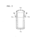
- the external camera 11 includes a front camera 11 a (imaging unit), a rear camera 11b (imaging unit), a left camera 11c (imaging unit), and a right camera 11d (imaging unit).
- the imaging region of the front camera 11a is a front peripheral region in the external environment of the vehicle.
- the imaging region of the rear camera 11b is a rear peripheral region in the external environment of the vehicle.
- the imaging regions of the left camera 11c and the right camera 11d are left and right peripheral regions in the external environment of the vehicle, respectively.
- the cameras 11a, 11b, 11c, and 11d can capture images from a visible-light region to a near-infrared region.
- the external camera 11 performs predetermined image processing, such as filtering, binarization, and the like on the images obtained by the cameras 11a, 11b, 11c, and 11d.
- the external camera 11 generates image data of pixels in a two-dimensional array and outputs the image data to the image processing apparatus 20.
- the front camera 11a is installed at the front grille or the like of the vehicle.
- the rear camera 11b is installed at the backdoor, tailgate or the like of the vehicle.
- the left camera 11c and the right camera 11d are installed at the lower ends or the like of the left and right side mirrors ML and MR of the vehicle.
- the near-infrared LED 12 is installed at the side mirror (for example, the left side mirror ML) and the like on the front passenger seat side of the vehicle.
- the near-infrared LED 12 is turned on or off under the control of the image processing apparatus 20 and irradiates a predetermined region on the front passenger seat side (for example, the imaging region of the external camera 11 on the front passenger seat side, that is, the peripheral region on the left side of the vehicle as the imaging region of the left camera 11c) in response to the lighting-up of the headlight (not shown) during nighttime or the like.
- the vehicle state sensor 13 includes a wheel speed sensor 31, a steering angle sensor 32, a shift position sensor 33, and the like.
- the wheel speed sensor 31 detects, as a quantity for the vehicle state of the present-vehicle, the rotation speed (wheel speed) of the driving wheel and the like.
- the steering angle sensor 32 detects a steering angle (for example, the direction and degree of a steering angle input by a driver) or an actual steering angle (wheel turning angle) according to the steering angle.
- the shift position sensor 33 detects a shift position according to the state of a transmission mechanism (not shown) which is selected by the driver with a select lever (not shown).
- the navigation device 14 carries out map matching processing on the basis of the current position of the vehicle and map data which are stored in advance.
- the navigation device 14 carries out processing such as route searching and route guidance with respect to a destination which is set in accordance with an input operation or the like by the operator, and outputs control commands which instruct the operations of the display device 19 and a speaker (not shown).
- the operating switch 15 outputs various kinds of command signals depending on the operation selected by the driver, for example, instructions to select various kinds of menu items on the display screen of the display device 19.
- the switch 16 outputs various kinds of command signals for display switching on the display screen of the display device 19 depending on the operation selected by the driver.
- the retraction switch 17 outputs various kinds of command signals to the side mirror actuator 18 which carries out the retraction, extension, angle change, and the like of the left and right side mirrors ML and MR of the vehicle depending on the operation of the driver.
- the display device 19 carries out various kinds of displays under the control of the image processing apparatus 20.
- the position of the present-vehicle and various kinds of guide displays can be displayed on the display screen of the display device 19 so as to be superimposed on the image data.
- the image processing apparatus 20 includes, for example, an LED control unit 41, an image processing unit 42, a storage unit 44, and a display control unit 45.
- the LED control unit 41 controls the turning on or off of the near-infrared LED 12 in response to the lighting-up of the headlight (not shown) during nighttime or the like and in response to a period in which an image of a side view SV described below is displayed on the display screen of the display device 19.
- the image processing unit 42 generates and outputs converted images corresponding to a predetermined visual field display on the basis of image data output from the respective cameras 11 a, 11b, 11c, and 11d of the external camera 11 by predetermined conversion processing.
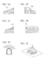
- the predetermined visual field display includes, for example, display (front view FV) of the front region of the vehicle shown in FIG. 3A , display (rear view RV) of the rear region of the vehicle shown in FIG. 3B , display (side view SV) of the left and right front regions of the vehicle shown in FIG. 3C , display (mirror view MV) of the left and right rear regions of the vehicle shown in FIG. 3D in which the regions reflected in the left and right side mirrors ML and MR are virtually reproduced, display (front blind view FBV) shown in FIG. 3E in which the display region is expanded left and right in the front region of the vehicle, display (ground view GV) of an overhead view of the peripheral region of the vehicle shown in FIG. 3F , and the like.
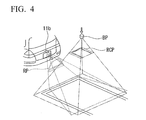
- the image processing unit 42 When generating the image of the ground view GV, as shown in FIG. 4 , the image processing unit 42 carries out viewpoint conversion on image data of the imaging regions of the respective cameras 11a, 11b, 11c, and 11d (for example, image data RP of the rear region of the vehicle shown in FIG. 4 ) while correcting image distortion or the like so as to provide images as viewed downward from a predetermined viewpoint BP above the vehicle in the vertical direction (for example, a converted image RCP shown in FIG. 4 ).
- An image in a predetermined field angle range for each converted image (for example, a front extracted image PF, a rear extracted image PR, a left extracted image PSL, or a right extracted image PSR) is extracted from each of the converted images obtained by the conversion processing such that the boundary positions thereof match each other. Then, as shown in FIGS. 5A and 5B , the images (the extracted images PF, PR, PSL, and PSR) are combined to generate a combined image, and the combined image is output as the image of the ground view GV. In the combined image, a predetermined mask line MB is provided at the boundary between adjacent extracted images.
- a predetermined mask line MB is provided at the boundary between adjacent extracted images.
- the imaging regions of the left camera 11c and the right camera 11d change depending on the opening/closing of the left and right side mirrors ML and MR (that is, extension and retraction).
- the image processing unit 42 changes the contents of the viewpoint conversion processing in accordance with the extension and retraction of the left and right side mirrors ML and MR and also changes a predetermined field angle range for each converted image (that is, the extraction ranges for extracting the extracted images PF, PR, PSL, and PSR from the respective converted images).
- the image of the ground view GV is generated which displays the same predetermined peripheral region by changing the boundary position between the images constituting the combined image (that is, the extracted images PF, PR, PSL, and PSR), regardless of the extension and retraction of the left and right side mirrors ML and MR.
- the ends of the side mirrors ML and MR are moved upward in the vertical direction, so the inclination angles of the side mirrors ML and MR with respect to the horizontal direction may be changed.
- the cameras 11c and 11d are set to capture the images of only the peripheral regions on the left and right sides of the vehicle in the extended state of the left and right side mirrors ML and MR. However, the imaging regions of the cameras 11c and 11d unnecessarily include the left and right portions of the vehicle main body and are shifted to the rear side of the vehicle in the retracted state of the left and right side mirrors ML and MR.
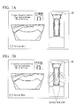
- the image of the ground view GV in the retracted state of the left and right side mirrors ML and MR (for example, the image of the ground view GV in the retracted state shown in FIG. 7B ) is generated by the same processing (that is, the same viewpoint conversion processing, and the processing for aligning the extraction ranges for extracting the extracted images PSL and PSR and the boundary positions between the extracted images PF, PR, PSL, and PSR constituting the combined image) as the processing for generating the image of the ground view GV in the extended state of the left and right side mirrors ML and MR (for example, the image of the ground view GV in the extended state shown in FIG.
- the same processing that is, the same viewpoint conversion processing, and the processing for aligning the extraction ranges for extracting the extracted images PSL and PSR and the boundary positions between the extracted images PF, PR, PSL, and PSR constituting the combined image
- an appropriate image as viewed downward from a predetermined viewpoint BP may not be obtained. Further, the predetermined peripheral regions on the left and right sides of the vehicle may not be displayed, and the boundary positions may be misaligned with respect to other extracted images PF and PR constituting the combined image.
- the image processing unit 42 first changes the contents of the viewpoint conversion processing in accordance with the extension and retraction of the left and right side mirrors ML and MR.
- the image processing unit 42 also changes the predetermined field angle range for each converted image (that is, the extraction ranges for extracting the extracted images PF, PR, PSL, and PSR from the respective converted images).
- the predetermined field angle range for each converted image that is, the extraction ranges for extracting the extracted images PF, PR, PSL, and PSR from the respective converted images.
- appropriate extracted images PSL and PSR are extracted which display the same predetermined peripheral regions on the left and right sides of the vehicle as viewed downward from a predetermined viewpoint BP, regardless of the extension and retraction of the left and right side mirrors ML and MR.
- the imaging regions of the cameras 11c and 11d in the retracted state of the left and right side mirrors ML and MR may be shifted to the rear side of the vehicle compared to the extended state of the left and right side mirrors ML and MR, so a region that cannot be imaged may be generated.
- the boundary positions between the front extracted image PF, the left extracted image PSL, and the right extracted image PSR are especially shifted to the rear side of the vehicle in the retracted state of the left and right side mirrors ML and MR as shown in FIG. 5B compared to the extended state of the left and right side mirrors ML and MR shown in FIG. 5A .
- the boundary positions between the extracted images PF, PSL, and PSR in the combined image are changed.
- the extraction ranges for extracting the extracted images PF, PR, PSL, and PSR from the respective converted images are changed in advance.
- the mask line MB which indicates each boundary position between the front extracted image PF, the left extracted image PSL, and the right extracted image PSR is inclined forward at a first predetermined angle ⁇ with respect to the left-right direction of the vehicle.
- the mask line MB which indicates each boundary position between the front extracted image PF, the left extracted image PSL, and the right extracted image PSR is inclined forward at a second predetermined angle ⁇ ( ⁇ ) smaller than the first predetermined angle ⁇ with respect to the left-right direction of the vehicle.
- the image processing unit 42 outputs, for example, the converted images of a front view FV shown in FIG. 8A , a rear view RV shown in FIG. 8B , left and right side views SV shown in FIGS. 8C and 8D , left and right mirror views MV shown in FIGS. 8E and 8F , a front blind view FBV shown in FIG. 8G , and a ground view GV shown in FIG. 8H .
- the display control unit 45 displays a navigation screen according to various kinds of operations of the navigation device 14 on the display screen of the display device 19.
- the display control unit 45 displays the converted images on the display screen of the display device 19 by a predetermined combination set in advance, a predetermined combination according to command signals output from the operating switch 15 or the switch 16, or a predetermined combination according to detection signals output from the vehicle state sensor 13.
- the display control unit 45 acquires various kinds of messages and images stored in the storage unit 44 and displays the messages or images on the display screen of the display device 19.
- various kinds of guide displays for assisting the driving of the driver for example, an indicator guide line DL concerning a predetermined position at the periphery of the vehicle shown in FIGS. 8A to 8F and 8H , an expected guide line EL concerning the traveling trace of the vehicle shown in the FIGS. 8A and 8H , and the like) are displayed so as to be superimposed on the converted images.
- the display control unit 45 selects four display modes, a display mode based on the combination of a front view FV and a ground view GV shown in FIG. 9A , a display mode based on a front blind view FBV shown in FIG. 9B , a display mode based on the combination of left and right side views SV shown in FIG.
- the display control unit 45 displays one of the display modes on the display screen of the display device 19 so as to be switched in accordance with a command signal output from the switch 16.
- the display control unit 45 acquires display mode indication images (image indicator display) IP, an imaging region indication image CP, various kinds of messages (for example, "Please Directly Confirm Your Surroundings While Driving.” and the like), menu display, help display, and the like from the storage unit 44, and displays them on the display screen of the display device 19.
- the display mode indication images IP displayed on the display screen represent switchable display modes.
- the display mode indicator images IP is disposed in an upper portion of the display device 19. Therefore, the driver can recognize the display mode indicator images IP more clearly.
- the imaging region indication image CP displayed on the display screen schematically shows the imaging region of the external camera 11 corresponding to a converted image being displayed.
- the display mode indication images IP include, as switchable display modes, an image F ⁇ G) representing the combination of the front view FV and the ground view GV, an image (FB) representing the front blind view FBV, an image (S) representing the combination of the left and right side views SV or only the left side view SV, an image (R ⁇ G) representing the combination of the rear view RV and the ground view GV, and an image (R ⁇ M) representing the combination of the rear view RV and the left and right mirror views MV.
- an image F ⁇ G representing the combination of the front view FV and the ground view GV
- an image (FB) representing the front blind view FBV
- an image (S) representing the combination of the left and right side views SV or only the left side view SV
- an image (R ⁇ G) representing the combination of the rear view RV and the ground view GV
- an image (R ⁇ M) representing the combination of the rear view RV and the left and right mirror views MV.
- the display mode indication image IP corresponding to a display mode being displayed on the display screen of the display device 19 is highlighted by increasing the contrast or size, or by changing the display color with respect to the display mode indication images IP corresponding to other switchable display modes.
- the display control unit 45 displays a first auxiliary display mode indication image (image indicator display) IPa or a second auxiliary display mode indication image (image indicator display) IPb which indicates a mutually switchable display mode (that is, the display mode based on the combination of the left and right side views SV or the display mode based only on the left side view SV).
- the first auxiliary display mode indication image IPa (long push: left) indicates that when the operating switch 15 is pushed for a long time, the display mode based on the combination of the left and right side views SV can be switched to the display mode based only on the left side view SV.
- the second auxiliary display mode indication image IPb (long push: left/right) indicates that when the operating switch 15 is pushed for a long time, the display mode based only on the left side view SV can be switched to the display mode based on the combination of the left and right side views SV.
- the display control unit 45 displays the image of the front view FV and the image of the ground view GV on the display screen of the display device 19 so as to be arranged in the left-right direction, as shown in FIG. 9A .
- the image of the rear view RV and the image of the ground view GV are displayed on the display screen of the display device 19 so as to be arranged in the left-right direction.
- the image of the left side view SV and the image of the right side view SV are displayed on the display screen of the display device 19 so as to be arranged in the left-right direction.
- the combination of the rear view RV and the left and right mirror views MV is selected.
- the image of the left mirror view MV and the image of the right mirror view MV are arranged in the left-right direction at the upper space, and the rear view RV is arranged at the lower space. In this case, as shown in FIG.
- the discomfort that the driver may feel with respect to the display mode can be suppressed, and visibility can be improved, as compared with a case where the image of the rear view RV is arranged at the upper space and the images of the left and right mirror views MV are arranged at the lower space.
- the image of the ground view GV which is combined with the front view FV at the time of the forward movement of the vehicle and the image of the ground view GV which is combined with the rear view RV at the time of the backward movement of the vehicle are the same (that is, the same display mode in which the field angle ranges of the extracted images PF, PR, PSL, and PSR constituting the image of the ground view GV, the boundary positions between the extracted images, and the like are unchanged).
- the display control unit 45 selects the display mode based on the combination of the front view FV or the rear view RV and the ground view GV and automatically displays on the display screen of the display device 19. After the navigation device 14 is activated, as shown in FIG. 11B , the display mode is switched to a predetermined navigation screen.
- the display control unit 45 stops display of the images of the left and right side views SV and the left and right mirror views MV in the retracted state of the left and right side mirrors ML and MR. Further, a predetermined mask image MP covering the display regions of the respective images and a predetermined message (for example, "Side Mirrors in Retracted State/Not Displayed” or the like) are displayed to indicate that display based on image data output from the left camera 11c and the right camera 11d in the retracted state of the left and right side mirrors ML and MR has been stopped.
- a predetermined mask image MP covering the display regions of the respective images and a predetermined message (for example, "Side Mirrors in Retracted State/Not Displayed" or the like) are displayed to indicate that display based on image data output from the left camera 11c and the right camera 11d in the retracted state of the left and right side mirrors ML and MR has been stopped.
- the images of the ground view GV, the front view FV, and the rear view RV are displayed on the display screen of the display device 19, regardless of the extension and retraction of the left and right side mirrors ML and MR.
- FIGS. 12B and 12C display based on the images of the left side view SV and the right side view SV is stopped in the retracted state of the left and right side mirrors ML and MR, and a predetermined mask image MP covering the display regions of the respective images is displayed.
- the contents of the viewpoint conversion processing, the predetermined field angle range for each converted image, and the boundary positions between the extracted images PF, PR, PSL, and PSR are changed.
- the display control unit 45 switches between display of the converted images output from the image processing unit 42 (display of a multi-view screen) and a display of a navigation screen concerning various kinds of operations of the navigation device 14 automatically or in accordance with the command signals output from the switch 16.
- the display control unit 45 determines whether or not the vehicle speed according to the detection signal output from the wheel speed sensor 31 of the vehicle state sensor 13 is equal to or lower than a predetermined low side determination threshold value VthL (for example, 12 km/h or the like).
- a predetermined low side determination threshold value VthL for example, 12 km/h or the like.
- the set screen which is displayed when the vehicle speed is higher than the predetermined low side determination threshold value VthL has the same screen layout as the multi-view screen which is displayed when the vehicle speed becomes equal to or lower than the predetermined low side determination threshold value VthL.
- the set screen is displayed which has the same screen layout as the display mode based on the combination of the front view FV and the ground view GV.
- a predetermined mask image MP is displayed which covers the display regions of the respective images in respective visual field display (that is, the front view FV, the rear view RV, the side view SV, the mirror view MV, the front blind view FBV, and the ground view GV). Further, a predetermined message (for example, "Not Displayed” or the like) is displayed to indicate that display based on image data output from the cameras 11a, 11b, 11c, and 11d of the external camera 11 has been stopped.
- a predetermined message for example, "Be Displayed at 12 km/h or Lower” or the like
- a predetermined message is also displayed to indicate that display based on image data output from the cameras 11a, 11b, 11c, and 11d of the external camera 11 will be made (that is, the multi-view screen is displayed) when the vehicle speed becomes equal to or lower than the predetermined low side determination threshold value VthL.
- a vehicle image (vehicle icon) VP is displayed on the image of the ground view GV on the multi-view screen and on the set screen or the like which has the same screen layout as the display mode having the ground view GV.
- the display control unit 45 appropriately changes the display state (for example, luminance or color) of the vehicle image (vehicle icon) VP between a plurality of different display states shown in FIG. 14 in accordance with the lighting state of the headlight (not shown) or the near-infrared LED 12, the brightness of other images on the display screen, the presence/absence of the mask image MP, or the like.
- a vehicle icon VP for example, with relatively large luminance is displayed.
- a vehicle icon VP with relatively little luminance is displayed.
- the vehicle icon VP with least luminance is displayed.
- the vehicle surroundings monitoring apparatus 10 of the embodiment has the above-described configuration. Next, the operation of the vehicle surroundings monitoring apparatus 10, especially, the switching operation of the display screen by the display control unit 45 will be described.
- Step S01 of FIG. 15 it is determined whether or not the shift position in the detection signal output from the shift position sensor 33 is in the reverse position for backward movement.
- Step S02 a below-described processing in a shift position except for the reverse position is carried out (the vehicle is engaged in a gear other than reverse), and then the process progresses to "RETURN".
- Step S03 the multi-view screen is displayed on the display screen of the display device 19.
- a screen for example, the navigation screen or the like
- the same multi-view screen as the previous multi-view screen is displayed. That is, if the previous multi-view screen corresponded to the display mode based on the combination of the front view FV and the ground view GV, the multi-view screen of the same display mode is displayed. Meanwhile, when the current shift position is changed from the shift position when the previous multi-view screen was displayed, the multi-view screen of the display mode according to the current shift position is displayed.
- the multi-view screen is displayed which is different from the previous multi-view screen and corresponds to the display mode based on the combination of the front view FV and the ground view GV according to predetermined initial settings.
- Step S04 it is determined whether or not the switch 16 is turned on.
- Step S05 the display mode of the multi-view screen is switched to a plurality of prescribed switchable display modes in a predetermined sequence (for example, the sequence of the display mode based on the combination of the rear view RV and the ground view GV, the display mode based on the combination of the rear view RV and the left and right mirror views MV, the display mode based on the combination of the rear view RV and the ground view GV, ).
- a predetermined sequence for example, the sequence of the display mode based on the combination of the rear view RV and the ground view GV, the display mode based on the combination of the rear view RV and the left and right mirror views MV, the display mode based on the combination of the rear view RV and the ground view GV, .
- Step S06 it is determined whether or not the retraction switch 17 is turned on.
- Step S07 a multi-view screen (in the retracted state) corresponding to the retracted state of the left and right side mirrors ML and MR is displayed, and then the process progresses to "RETURN".
- Step S08 a multi-view screen (not in the retracted state) corresponding to the extended state of the left and right side mirrors ML and MR is displayed, and then the process progresses to "RETURN".
- Step S11 of FIG. 16 it is determined whether or not the navigation screen is being displayed.
- Step S12 it is determined whether or not the vehicle speed is equal to or lower than the predetermined low side determination threshold value VthL (for example, 12 km/h or the like).
- VthL for example, 12 km/h or the like.
- Step S 13 display is switched from the navigation screen to a multi-view screen, and then the process progresses to "RETURN".
- the same multi-view screen as the previous multi-view screen, or a multi-view screen according to the predetermined initial settings is displayed.
- Step S 14 it is determined whether or not the switch 16 is turned on.
- Step S 15 display is switched from the navigation screen to the set screen, and then the process progresses to "RETURN".
- Step S16 it is determined whether or not a multi-view screen is being displayed.
- Step S 17 it is determined whether or not the vehicle speed is higher than a predetermined high side determination threshold vale VthH (for example, 15 km/h or the like).
- Step S 18 display is switched from the multi-view screen to the navigation screen, and then the process progresses to "RETURN".
- Step S 19 it is determined whether or not the switch 16 is turned on.
- Step S20 the display mode of the multi-view screen is switched to a plurality of prescribed switchable display modes in a predetermined sequence (for example, the sequence of the display mode based on the combination of the front view FV and the ground view GV, the display mode based on the front blind view FBV, the display mode based on the side view SV, the display mode based on the combination of the front view FV and the ground view GV, .
- a predetermined sequence for example, the sequence of the display mode based on the combination of the front view FV and the ground view GV, the display mode based on the front blind view FBV, the display mode based on the side view SV, the display mode based on the combination of the front view FV and the ground view GV, .
- Step S21 it is determined whether or not the retraction switch 17 is turned on.
- Step S22 a multi-view screen (in the retracted state) corresponding to the retracted state of the left and right side mirrors ML and MR is displayed, and then the process progresses to "RETURN".
- Step S23 a multi-view screen (not in the retracted state) corresponding to the extended state of the left and right side mirrors ML and MR is displayed, and then the process progresses to "RETURN".
- Step S24 it is determined whether or not a set screen is being displayed.
- Step S25 it is determined whether or not the vehicle speed is equal to or lower than the predetermined low side threshold value VthL (for example, 12 km/h or the like).
- VthL for example, 12 km/h or the like.
- Step S26 display is switched from the navigation screen to the multi-view screen, and then the process progresses to "RETURN".
- the same multi-view screen as the previous multi-view screen, or a multi-view screen according to the predetermined initial setting is displayed.
- Step S27 it is determined whether or not the switch 16 is turned on. When the determination result is "NO”, the process progresses to "RETURN".
- Step S28 display is switched from the navigation screen to the set screen, and then the process progresses to "RETURN".
- the driver can easily recognize the imaging regions of the external camera 11 corresponding to the converted images displayed on the display device 19 (that is, the display regions displayed by the converted images in the external region of the present-vehicle) and selectable converted images at the time of display switching by the display mode indication image IP, the first auxiliary display mode indication image IPa, and the second auxiliary display mode indication image IPb.
- the display state (for example, luminance or color) of the vehicle image (vehicle icon) VP which is displayed in the image of the ground view GV on the multi-view screen and the set screen or the like which has the same screen layout as the display mode having the ground view GV is appropriately changed between a plurality of different display states in accordance with the lighting state of the headlight (not shown) or the near-infrared LED 12, the brightness of other images on the display screen, the presence/absence of the mask image MP, or the like. Therefore, the driver's visibility of the display screen can be improved.
- a vehicle surroundings monitoring apparatus includes: a plurality of imaging units (11) which capture an external region of a present-vehicle and output images; a display unit (19) which is installed in an interior of the present-vehicle; a selector (16) which selects an image to be displayed on the display unit (19) from the images output from the imaging units (11); and a display control unit (45) which displays the images output from the imaging units (11) on the display unit (19) so as to be switched in accordance with a selection by the selector (16) and displays an image indicator display (IP) indicating a display region in the external region of the present-vehicle corresponding to the images so as to be switched by the selector (16) on the display unit (19).
- IP image indicator display
Landscapes
- Engineering & Computer Science (AREA)
- Multimedia (AREA)
- Mechanical Engineering (AREA)
- Closed-Circuit Television Systems (AREA)
- Image Processing (AREA)
- Image Analysis (AREA)
- Fittings On The Vehicle Exterior For Carrying Loads, And Devices For Holding Or Mounting Articles (AREA)
Abstract
Description
- The present invention relates to a vehicle surroundings monitoring apparatus.
- A vehicle periphery monitoring apparatus is known in which, when the display device displays images selected from captured images in multiple directions of the periphery of a vehicle, an identification image for identifying an imaging direction is superimposed on the selected images (for example, see Japanese Unexamined Patent Application, First Publication No.
2004-96359 - In the vehicle periphery monitoring apparatus which is an example of the conventional techniques, an identification image for identifying the imaging direction of a captured image which is actually displayed on the display screen is simply superimposed on the captured image. For this reason, there is a problem in that a driver cannot easily recognize which imaging direction can be selected for displaying the captured image.
- The invention was conceived in view of the above-described circumstances, and it is an object thereof to provide a vehicle surroundings monitoring apparatus which enables a driver to easily recognize a display region in an external region of a vehicle corresponding to an image displayed on a display device and to easily recognize selectable display regions.
- In order to achieve the above-described object, a vehicle surroundings monitoring apparatus of the invention, includes: a plurality of imaging units which capture an external region of a present-vehicle and output images; a display unit which is installed in an interior of the present-vehicle; a selector which selects an image to be displayed on the display unit from the images output from the imaging units; and a display control unit which displays the images output from the imaging units on the display unit so as to be switched in accordance with a selection by the selector and displays an image indicator display indicating a display region in the external region of the present-vehicle corresponding to the images so as to be switched by the selector on the display unit.
- Moreover, it is preferable that, in the vehicle surroundings monitoring apparatus in the invention, the image indicator display be highlighted corresponding to the images displayed on the display unit in the display control unit.
- Moreover, it is preferable that, in the vehicle surroundings monitoring apparatus in the invention, the image indicator display be disposed in an upper portion of the display unit.
- According to the vehicle surroundings monitoring apparatus of the invention, the driver can easily recognize a display region in the external region of the present-vehicle corresponding to an image displayed on the display device and the selectable display regions for switching images.
-
-
FIG. 1 is a configuration diagram of a vehicle surroundings monitoring apparatus according to an embodiment of the invention. -
FIG. 2 is a diagram showing the arrangement of an external camera in the vehicle surroundings monitoring apparatus according to the embodiment of the invention. -
FIG. 3A is a diagram showing a predetermined external region corresponding to a visual field display in the vehicle surroundings monitoring apparatus according to the embodiment of the invention. -
FIG. 3B is a diagram showing a predetermined external region corresponding to a visual field display in the vehicle surroundings monitoring apparatus according to the embodiment of the invention. -
FIG. 3C is a diagram showing a predetermined external region corresponding to a visual field display in the vehicle surroundings monitoring apparatus according to the embodiment of the invention. -
FIG. 3D is a diagram showing a predetermined external region corresponding to a visual field display in the vehicle surroundings monitoring apparatus according to the embodiment of the invention. -
FIG. 3E is a diagram showing a predetermined external region corresponding to a visual field display in the vehicle surroundings monitoring apparatus according to the embodiment of the invention. -
FIG. 3F is a diagram showing a predetermined external region corresponding to a visual field display in the vehicle surroundings monitoring apparatus according to the embodiment of the invention. -
FIG. 4 is a diagram showing examples of image data RP obtained by a rear camera in the vehicle surroundings monitoring apparatus according to the embodiment of the invention and converted image data RCP obtained by viewpoint conversion with respect to the image data RP. -
FIG. 5A is a diagram showing an image of a ground view GV corresponding to the extension of left and right side mirrors ML and MR in the vehicle surroundings monitoring apparatus according to the embodiment of the invention. -
FIG. 5B is a diagram showing an image of a ground view GV according to the retraction of left and right side mirrors ML and MR in the vehicle surroundings monitoring apparatus according to the embodiment of the invention. -
FIG. 6A is a diagram showing the extended state of a right side mirror MR in the vehicle surroundings monitoring apparatus according to the embodiment of the invention. -
FIG. 6B is a diagram showing the extended n state of a left side mirror ML in the vehicle surroundings monitoring apparatus according to the embodiment of the invention. -
FIG. 6C is a diagram showing the retracted state of a right side mirror MR in the vehicle surroundings monitoring apparatus according to the embodiment of the invention. -
FIG. 6D is a diagram showing the retracted state of a left side mirror ML in the vehicle surroundings monitoring apparatus according to the embodiment of the invention. -
FIG. 7A is an image of a ground view GV in the extended state of left and right side mirrors ML and MR in the vehicle surroundings monitoring apparatus according to the embodiment of the invention. -
FIG. 7B is an image of a ground view GV in the retracted state of left and right side mirrors ML and MR in the vehicle surroundings monitoring apparatus according to a comparative example of the embodiment of the invention. -
FIG. 8A is a diagram showing an example of converted images which are output from an image processing unit in the vehicle surroundings monitoring apparatus according to the embodiment of the invention. -
FIG. 8B is a diagram showing an example of converted images which are output from an image processing unit in the vehicle surroundings monitoring apparatus according to the embodiment of the invention. -
FIG. 8C is a diagram showing an example of converted images which are output from an image processing unit in the vehicle surroundings monitoring apparatus according to the embodiment of the invention. -
FIG. 8D is a diagram showing an example of converted images which are output from an image processing unit in the vehicle surroundings monitoring apparatus according to the embodiment of the invention. -
FIG. 8E is a diagram showing an example of converted images which are output from an image processing unit in the vehicle surroundings monitoring apparatus according to the embodiment of the invention. -
FIG. 8F is a diagram showing an example of converted images which are output from an image processing unit in the vehicle surroundings monitoring apparatus according to the embodiment of the invention. -
FIG. 8G is a diagram showing an example of converted images which are output from an image processing unit in the vehicle surroundings monitoring apparatus according to the embodiment of the invention. -
FIG. 8H is a diagram showing an example of converted images which are output from an image processing unit in the vehicle surroundings monitoring apparatus according to the embodiment of the invention. -
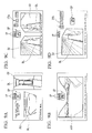
FIG. 9A is a diagram showing an example of a display screen in the vehicle surroundings monitoring apparatus according to the embodiment of the invention. -
FIG. 9B is a diagram showing an example of a display screen in the vehicle surroundings monitoring apparatus according to the embodiment of the invention. -
FIG. 9C is a diagram showing an example of a display screen in the vehicle surroundings monitoring apparatus according to the embodiment of the invention. -
FIG. 9D is a diagram showing an example of a display screen in the vehicle surroundings monitoring apparatus according to the embodiment of the invention. -
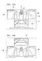
FIG. 10A is a diagram showing an example of a display screen in the vehicle surroundings monitoring apparatus according to the embodiment of the invention. -
FIG. 10B is a diagram showing an example of a display screen in the vehicle surroundings monitoring apparatus according to the embodiment of the invention. -
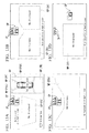
FIG. 11A is a diagram showing an example of a display screen immediately after the starting of a vehicle in the vehicle surroundings monitoring apparatus according to the embodiment of the invention. -
FIG. 11B is a diagram showing an example of a display screen after a predetermined time has passed from the starting of a vehicle in the vehicle surroundings monitoring apparatus according to the embodiment of the invention. -
FIG. 11C is a diagram showing an example of a display screen immediately after the starting of a vehicle in the vehicle surroundings monitoring apparatus according to a comparative example of the embodiment of the invention. -
FIG. 12A is a diagram showing an example of a display screen in the retracted state of left and right side mirrors ML and MR in the vehicle surroundings monitoring apparatus according to the embodiment of the invention. -
FIG. 12B is a diagram showing an example of a display screen in the retracted state of left and right side mirrors ML and MR in the vehicle surroundings monitoring apparatus according to the embodiment of the invention. -
FIG. 12C is a diagram showing an example of a display screen in the retracted state of left and right side mirrors ML and MR in the vehicle surroundings monitoring apparatus according to the embodiment of the invention. -
FIG. 13A is a diagram showing an example of a set screen of a display screen in the vehicle surroundings monitoring apparatus according to the embodiment of the invention. -
FIG. 13B is a diagram showing an example of a set screen of a display screen in the vehicle surroundings monitoring apparatus according to the embodiment of the invention. -
FIG. 13C is a diagram showing an example of a set screen of a display screen in the vehicle surroundings monitoring apparatus according to the embodiment of the invention. -
FIG. 13D is a diagram showing an example of a set screen of a display screen in the vehicle surroundings monitoring apparatus according to the embodiment of the invention. -
FIG. 14 is a diagram showing an example of a display state of a vehicle icon VP on a display screen in the vehicle surroundings monitoring apparatus according to the embodiment of the invention. -
FIG. 15 is a flowchart showing the operation of the vehicle surroundings monitoring apparatus according to the embodiment of the invention. -
FIG. 16 is a flowchart of a processing in a shift position except for a reverse position shown inFIG. 15 . - A vehicle surroundings monitoring apparatus according to an embodiment of the invention will be described with reference to the accompanying drawings.
- As shown in
FIG. 1 , a vehiclesurroundings monitoring apparatus 10 according to the embodiment includes an external camera 11 (imaging unit), a near-infrared LED 12, avehicle state sensor 13, anavigation device 14, an operatingswitch 15, a switch (selector) 16, aretraction switch 17, aside mirror actuator 18, a display device (display unit) 19, and animage processing apparatus 20. Thedisplay device 19 is installed in an interior of the vehicle. Theimage processing apparatus 20 has an electronic circuit including a CPU and the like. The vehiclesurroundings monitoring apparatus 10 is installed in a vehicle and captures images of the external environment of the vehicle by theexternal camera 11. - As shown in
FIG. 2 , theexternal camera 11 includes afront camera 11 a (imaging unit), arear camera 11b (imaging unit), aleft camera 11c (imaging unit), and aright camera 11d (imaging unit). The imaging region of thefront camera 11a is a front peripheral region in the external environment of the vehicle. The imaging region of therear camera 11b is a rear peripheral region in the external environment of the vehicle. The imaging regions of theleft camera 11c and theright camera 11d are left and right peripheral regions in the external environment of the vehicle, respectively. Thecameras external camera 11 performs predetermined image processing, such as filtering, binarization, and the like on the images obtained by thecameras external camera 11 generates image data of pixels in a two-dimensional array and outputs the image data to theimage processing apparatus 20. - The
front camera 11a is installed at the front grille or the like of the vehicle. Therear camera 11b is installed at the backdoor, tailgate or the like of the vehicle. Theleft camera 11c and theright camera 11d are installed at the lower ends or the like of the left and right side mirrors ML and MR of the vehicle. - The near-
infrared LED 12 is installed at the side mirror (for example, the left side mirror ML) and the like on the front passenger seat side of the vehicle. The near-infrared LED 12 is turned on or off under the control of theimage processing apparatus 20 and irradiates a predetermined region on the front passenger seat side (for example, the imaging region of theexternal camera 11 on the front passenger seat side, that is, the peripheral region on the left side of the vehicle as the imaging region of theleft camera 11c) in response to the lighting-up of the headlight (not shown) during nighttime or the like. - The
vehicle state sensor 13 includes awheel speed sensor 31, asteering angle sensor 32, ashift position sensor 33, and the like. Thewheel speed sensor 31 detects, as a quantity for the vehicle state of the present-vehicle, the rotation speed (wheel speed) of the driving wheel and the like. Thesteering angle sensor 32 detects a steering angle (for example, the direction and degree of a steering angle input by a driver) or an actual steering angle (wheel turning angle) according to the steering angle. Theshift position sensor 33 detects a shift position according to the state of a transmission mechanism (not shown) which is selected by the driver with a select lever (not shown). - The
navigation device 14 carries out map matching processing on the basis of the current position of the vehicle and map data which are stored in advance. Thenavigation device 14 carries out processing such as route searching and route guidance with respect to a destination which is set in accordance with an input operation or the like by the operator, and outputs control commands which instruct the operations of thedisplay device 19 and a speaker (not shown). - The operating
switch 15 outputs various kinds of command signals depending on the operation selected by the driver, for example, instructions to select various kinds of menu items on the display screen of thedisplay device 19. - The
switch 16 outputs various kinds of command signals for display switching on the display screen of thedisplay device 19 depending on the operation selected by the driver. - The
retraction switch 17 outputs various kinds of command signals to theside mirror actuator 18 which carries out the retraction, extension, angle change, and the like of the left and right side mirrors ML and MR of the vehicle depending on the operation of the driver. - The
display device 19 carries out various kinds of displays under the control of theimage processing apparatus 20. For example, in addition to image data output from theexternal camera 11, the position of the present-vehicle and various kinds of guide displays can be displayed on the display screen of thedisplay device 19 so as to be superimposed on the image data. - The
image processing apparatus 20 includes, for example, anLED control unit 41, animage processing unit 42, astorage unit 44, and adisplay control unit 45. - The
LED control unit 41 controls the turning on or off of the near-infrared LED 12 in response to the lighting-up of the headlight (not shown) during nighttime or the like and in response to a period in which an image of a side view SV described below is displayed on the display screen of thedisplay device 19. - The
image processing unit 42 generates and outputs converted images corresponding to a predetermined visual field display on the basis of image data output from therespective cameras external camera 11 by predetermined conversion processing. - The predetermined visual field display includes, for example, display (front view FV) of the front region of the vehicle shown in
FIG. 3A , display (rear view RV) of the rear region of the vehicle shown inFIG. 3B , display (side view SV) of the left and right front regions of the vehicle shown inFIG. 3C , display (mirror view MV) of the left and right rear regions of the vehicle shown inFIG. 3D in which the regions reflected in the left and right side mirrors ML and MR are virtually reproduced, display (front blind view FBV) shown inFIG. 3E in which the display region is expanded left and right in the front region of the vehicle, display (ground view GV) of an overhead view of the peripheral region of the vehicle shown inFIG. 3F , and the like. - When generating the image of the ground view GV, as shown in
FIG. 4 , theimage processing unit 42 carries out viewpoint conversion on image data of the imaging regions of therespective cameras FIG. 4 ) while correcting image distortion or the like so as to provide images as viewed downward from a predetermined viewpoint BP above the vehicle in the vertical direction (for example, a converted image RCP shown inFIG. 4 ). An image in a predetermined field angle range for each converted image (for example, a front extracted image PF, a rear extracted image PR, a left extracted image PSL, or a right extracted image PSR) is extracted from each of the converted images obtained by the conversion processing such that the boundary positions thereof match each other. Then, as shown inFIGS. 5A and 5B , the images (the extracted images PF, PR, PSL, and PSR) are combined to generate a combined image, and the combined image is output as the image of the ground view GV. In the combined image, a predetermined mask line MB is provided at the boundary between adjacent extracted images. - When the
left camera 11c and theright camera 11d of theexternal camera 11 are respectively provided at the lower ends of the left and right side mirrors ML and MR of the vehicle, the imaging regions of theleft camera 11c and theright camera 11d change depending on the opening/closing of the left and right side mirrors ML and MR (that is, extension and retraction). For this reason, theimage processing unit 42 changes the contents of the viewpoint conversion processing in accordance with the extension and retraction of the left and right side mirrors ML and MR and also changes a predetermined field angle range for each converted image (that is, the extraction ranges for extracting the extracted images PF, PR, PSL, and PSR from the respective converted images). The image of the ground view GV is generated which displays the same predetermined peripheral region by changing the boundary position between the images constituting the combined image (that is, the extracted images PF, PR, PSL, and PSR), regardless of the extension and retraction of the left and right side mirrors ML and MR. - As shown in
FIGS. 6A to 6D , when the left and right side mirrors ML and MR in the extended state are retracted, the ends of the side mirrors ML and MR are moved upward in the vertical direction, so the inclination angles of the side mirrors ML and MR with respect to the horizontal direction may be changed. Thecameras cameras - Accordingly, if the image of the ground view GV in the retracted state of the left and right side mirrors ML and MR (for example, the image of the ground view GV in the retracted state shown in
FIG. 7B ) is generated by the same processing (that is, the same viewpoint conversion processing, and the processing for aligning the extraction ranges for extracting the extracted images PSL and PSR and the boundary positions between the extracted images PF, PR, PSL, and PSR constituting the combined image) as the processing for generating the image of the ground view GV in the extended state of the left and right side mirrors ML and MR (for example, the image of the ground view GV in the extended state shown inFIG. 7A ), an appropriate image as viewed downward from a predetermined viewpoint BP may not be obtained. Further, the predetermined peripheral regions on the left and right sides of the vehicle may not be displayed, and the boundary positions may be misaligned with respect to other extracted images PF and PR constituting the combined image. - For this reason, the
image processing unit 42 first changes the contents of the viewpoint conversion processing in accordance with the extension and retraction of the left and right side mirrors ML and MR. Theimage processing unit 42 also changes the predetermined field angle range for each converted image (that is, the extraction ranges for extracting the extracted images PF, PR, PSL, and PSR from the respective converted images). Thus, appropriate extracted images PSL and PSR are extracted which display the same predetermined peripheral regions on the left and right sides of the vehicle as viewed downward from a predetermined viewpoint BP, regardless of the extension and retraction of the left and right side mirrors ML and MR. - The imaging regions of the
cameras FIG. 5B compared to the extended state of the left and right side mirrors ML and MR shown inFIG. 5A . In this way, the boundary positions between the extracted images PF, PSL, and PSR in the combined image are changed. In response to the change in the boundary positions, the extraction ranges for extracting the extracted images PF, PR, PSL, and PSR from the respective converted images are changed in advance. - In the extended state of the left and right side mirrors ML and MR shown in
FIG. 5A , the mask line MB which indicates each boundary position between the front extracted image PF, the left extracted image PSL, and the right extracted image PSR is inclined forward at a first predetermined angle α with respect to the left-right direction of the vehicle. Meanwhile, in the retracted state of the left and right side mirrors ML and MR shown inFIG. 5B , the mask line MB which indicates each boundary position between the front extracted image PF, the left extracted image PSL, and the right extracted image PSR is inclined forward at a second predetermined angle β (<α) smaller than the first predetermined angle α with respect to the left-right direction of the vehicle. Thus, the extraction region of the front extracted image PF is expanded and the extraction regions of the left extracted image PSL and the right extracted image PSR are reduced in the retracted state compared to the extended state of the left and right side mirrors ML and MR. - The
image processing unit 42 outputs, for example, the converted images of a front view FV shown inFIG. 8A , a rear view RV shown inFIG. 8B , left and right side views SV shown inFIGS. 8C and 8D , left and right mirror views MV shown inFIGS. 8E and 8F , a front blind view FBV shown inFIG. 8G , and a ground view GV shown inFIG. 8H . - The
display control unit 45 displays a navigation screen according to various kinds of operations of thenavigation device 14 on the display screen of thedisplay device 19. - The
display control unit 45 displays the converted images on the display screen of thedisplay device 19 by a predetermined combination set in advance, a predetermined combination according to command signals output from the operatingswitch 15 or theswitch 16, or a predetermined combination according to detection signals output from thevehicle state sensor 13. - When displaying the converted images output from the
image processing unit 42 on the display screen of thedisplay device 19, thedisplay control unit 45 acquires various kinds of messages and images stored in thestorage unit 44 and displays the messages or images on the display screen of thedisplay device 19. At the same time, various kinds of guide displays for assisting the driving of the driver (for example, an indicator guide line DL concerning a predetermined position at the periphery of the vehicle shown inFIGS. 8A to 8F and 8H , an expected guide line EL concerning the traveling trace of the vehicle shown in theFIGS. 8A and 8H , and the like) are displayed so as to be superimposed on the converted images. - It is assumed that the speed of the vehicle (vehicle speed) according to the detection signal output from the
wheel speed sensor 31 of thevehicle state sensor 13 is equal to or lower than a predetermined low side determination threshold value VthL, and the shift position in the detection signal output from theshift position sensor 33 is in a position (for example, a drive position for forward movement or the like) other than the reverse position for backward movement. In this case, thedisplay control unit 45 selects four display modes, a display mode based on the combination of a front view FV and a ground view GV shown inFIG. 9A , a display mode based on a front blind view FBV shown inFIG. 9B , a display mode based on the combination of left and right side views SV shown inFIG. 9C , and a display mode based on a left side view SV shown inFIG. 9D , from among a plurality of display modes set in advance. Thedisplay control unit 45 displays one of the display modes on the display screen of thedisplay device 19 so as to be switched in accordance with a command signal output from theswitch 16. - In this case, in addition to the converted images output from the
image processing unit 42, thedisplay control unit 45 acquires display mode indication images (image indicator display) IP, an imaging region indication image CP, various kinds of messages (for example, "Please Directly Confirm Your Surroundings While Driving." and the like), menu display, help display, and the like from thestorage unit 44, and displays them on the display screen of thedisplay device 19. The display mode indication images IP displayed on the display screen represent switchable display modes. The display mode indicator images IP is disposed in an upper portion of thedisplay device 19. Therefore, the driver can recognize the display mode indicator images IP more clearly. The imaging region indication image CP displayed on the display screen schematically shows the imaging region of theexternal camera 11 corresponding to a converted image being displayed. - The display mode indication images IP include, as switchable display modes, an image F·G) representing the combination of the front view FV and the ground view GV, an image (FB) representing the front blind view FBV, an image (S) representing the combination of the left and right side views SV or only the left side view SV, an image (R·G) representing the combination of the rear view RV and the ground view GV, and an image (R·M) representing the combination of the rear view RV and the left and right mirror views MV. As shown in
FIGS. 9A to 9D , the display mode indication image IP corresponding to a display mode being displayed on the display screen of thedisplay device 19 is highlighted by increasing the contrast or size, or by changing the display color with respect to the display mode indication images IP corresponding to other switchable display modes. - As shown in
FIGS. 9C and 9D , when the image (S) representing the combination of the left and right side views SV or only the left side view SV is displayed and highlighted as the display mode indication image IP, thedisplay control unit 45 displays a first auxiliary display mode indication image (image indicator display) IPa or a second auxiliary display mode indication image (image indicator display) IPb which indicates a mutually switchable display mode (that is, the display mode based on the combination of the left and right side views SV or the display mode based only on the left side view SV). - The first auxiliary display mode indication image IPa (long push: left) indicates that when the operating
switch 15 is pushed for a long time, the display mode based on the combination of the left and right side views SV can be switched to the display mode based only on the left side view SV. The second auxiliary display mode indication image IPb (long push: left/right) indicates that when the operatingswitch 15 is pushed for a long time, the display mode based only on the left side view SV can be switched to the display mode based on the combination of the left and right side views SV. - With regard to the combination of the front view FV and the ground view GV, the
display control unit 45 displays the image of the front view FV and the image of the ground view GV on the display screen of thedisplay device 19 so as to be arranged in the left-right direction, as shown inFIG. 9A . - With regard to the combination of the rear view RV and the ground view GV, the image of the rear view RV and the image of the ground view GV are displayed on the display screen of the
display device 19 so as to be arranged in the left-right direction. - With regard to the combination of the left and right side views SV, as shown in
FIG. 9C , the image of the left side view SV and the image of the right side view SV are displayed on the display screen of thedisplay device 19 so as to be arranged in the left-right direction. - When the shift position in the detection signal output from the
shift position sensor 33 is in the reverse position (the vehicle is engaged in a reverse gear), the combination of the rear view RV and the left and right mirror views MV is selected. As shown inFIG. 10A , on the display screen of thedisplay device 19, the image of the left mirror view MV and the image of the right mirror view MV are arranged in the left-right direction at the upper space, and the rear view RV is arranged at the lower space. In this case, as shown inFIG. 10B , the discomfort that the driver may feel with respect to the display mode can be suppressed, and visibility can be improved, as compared with a case where the image of the rear view RV is arranged at the upper space and the images of the left and right mirror views MV are arranged at the lower space. - The image of the ground view GV which is combined with the front view FV at the time of the forward movement of the vehicle and the image of the ground view GV which is combined with the rear view RV at the time of the backward movement of the vehicle are the same (that is, the same display mode in which the field angle ranges of the extracted images PF, PR, PSL, and PSR constituting the image of the ground view GV, the boundary positions between the extracted images, and the like are unchanged).
- When the ignition switch of the vehicle is turned on and the vehicle is started, the time which it takes to activate the
external camera 11 and theimage processing apparatus 20 is relatively shorter than the time which it takes to activate thenavigation device 14. For this reason, while thenavigation device 14 is being activated, as shown inFIG. 11A , thedisplay control unit 45 selects the display mode based on the combination of the front view FV or the rear view RV and the ground view GV and automatically displays on the display screen of thedisplay device 19. After thenavigation device 14 is activated, as shown inFIG. 11B , the display mode is switched to a predetermined navigation screen. Thus, it is possible to appropriately assist the driver to be aware of vehicle surroundings when the vehicle starts moving, without needing the driver to switch the display screen, as compared with a case where a predetermined activation screen shown inFIG. 11C is automatically displayed on the display screen of thedisplay device 19 while thenavigation device 14 is being activated. - When the
left camera 11c and theright camera 11 d of theexternal camera 11 are installed at the lower ends of the left and right side mirrors ML and MR of the vehicle, thedisplay control unit 45 stops display of the images of the left and right side views SV and the left and right mirror views MV in the retracted state of the left and right side mirrors ML and MR. Further, a predetermined mask image MP covering the display regions of the respective images and a predetermined message (for example, "Side Mirrors in Retracted State/Not Displayed" or the like) are displayed to indicate that display based on image data output from theleft camera 11c and theright camera 11d in the retracted state of the left and right side mirrors ML and MR has been stopped. - As shown in
FIG. 12A , the images of the ground view GV, the front view FV, and the rear view RV are displayed on the display screen of thedisplay device 19, regardless of the extension and retraction of the left and right side mirrors ML and MR. Meanwhile, as shown inFIGS. 12B and 12C , display based on the images of the left side view SV and the right side view SV is stopped in the retracted state of the left and right side mirrors ML and MR, and a predetermined mask image MP covering the display regions of the respective images is displayed. - As shown in
FIGS. 12A to 12C , even though the image (FB) representing the front blind view FBV is displayed as the display mode indication image IP, switching to the display mode based on the front blind view FBV is inhibited in the retracted state of the left and right side mirrors ML and MR. - In the retracted state of the left and right side mirrors ML and MR, for example, as shown in
FIGS. 12B and 12C , display of the first auxiliary display mode indication image IPa and the second auxiliary display mode indication image IPb which individually indicate the display mode based on the combination of the left and right side views SV and the display mode based only on the left side view SV is stopped. - As described above, in the retracted state of the left and right side mirrors ML and MR, with regard to the image of the ground view GV, the contents of the viewpoint conversion processing, the predetermined field angle range for each converted image, and the boundary positions between the extracted images PF, PR, PSL, and PSR are changed.
- As described below, the
display control unit 45 switches between display of the converted images output from the image processing unit 42 (display of a multi-view screen) and a display of a navigation screen concerning various kinds of operations of thenavigation device 14 automatically or in accordance with the command signals output from theswitch 16. - Especially, when switching display of the navigation screen to display of the multi-view screen in accordance with the command signal output from the
switch 16, thedisplay control unit 45 determines whether or not the vehicle speed according to the detection signal output from thewheel speed sensor 31 of thevehicle state sensor 13 is equal to or lower than a predetermined low side determination threshold value VthL (for example, 12 km/h or the like). When the vehicle speed is higher than the predetermined low side determination threshold value VthL, a predetermined set screen shown inFIGS. 13A to 13D is displayed until the vehicle speed becomes equal to or lower than the predetermined low side determination threshold value VthL. - The set screen which is displayed when the vehicle speed is higher than the predetermined low side determination threshold value VthL has the same screen layout as the multi-view screen which is displayed when the vehicle speed becomes equal to or lower than the predetermined low side determination threshold value VthL. In this case, when the vehicle speed is equal to or lower than the predetermined low side determination threshold value VthL, and the multi-view screen corresponding to the display mode based on the combination of the front view FV and the ground view GV is displayed, the set screen is displayed which has the same screen layout as the display mode based on the combination of the front view FV and the ground view GV.
- On the set screen, a predetermined mask image MP is displayed which covers the display regions of the respective images in respective visual field display (that is, the front view FV, the rear view RV, the side view SV, the mirror view MV, the front blind view FBV, and the ground view GV). Further, a predetermined message (for example, "Not Displayed" or the like) is displayed to indicate that display based on image data output from the
cameras external camera 11 has been stopped. On the set screen, a predetermined message (for example, "Be Displayed at 12 km/h or Lower" or the like) is also displayed to indicate that display based on image data output from thecameras external camera 11 will be made (that is, the multi-view screen is displayed) when the vehicle speed becomes equal to or lower than the predetermined low side determination threshold value VthL. - On the set screen, as shown in
FIGS. 13B and 13D , display of the first and second auxiliary display mode indication images IPa and IPb which individually indicate the display mode based on the combination of the left and right side views SV and the display mode based only on the left side view SV is stopped. - A vehicle image (vehicle icon) VP is displayed on the image of the ground view GV on the multi-view screen and on the set screen or the like which has the same screen layout as the display mode having the ground view GV.
- The
display control unit 45 appropriately changes the display state (for example, luminance or color) of the vehicle image (vehicle icon) VP between a plurality of different display states shown inFIG. 14 in accordance with the lighting state of the headlight (not shown) or the near-infrared LED 12, the brightness of other images on the display screen, the presence/absence of the mask image MP, or the like. - With regard to the image of the ground view GV on the multi-view screen, when the headlight (not shown) is turned on, a vehicle icon VP, for example, with relatively large luminance is displayed. When the headlight (not shown) is turned off, a vehicle icon VP with relatively little luminance is displayed. On the set screen, the vehicle icon VP with least luminance is displayed.
- The vehicle
surroundings monitoring apparatus 10 of the embodiment has the above-described configuration. Next, the operation of the vehiclesurroundings monitoring apparatus 10, especially, the switching operation of the display screen by thedisplay control unit 45 will be described. - In Step S01 of
FIG. 15 , it is determined whether or not the shift position in the detection signal output from theshift position sensor 33 is in the reverse position for backward movement. - When the determination result is "YES", the process progresses to Step S03 described below.
- When the determination result is "NO", the process progresses to Step S02. In Step S02, a below-described processing in a shift position except for the reverse position is carried out (the vehicle is engaged in a gear other than reverse), and then the process progresses to "RETURN".
- In Step S03, the multi-view screen is displayed on the display screen of the
display device 19. When a screen (for example, the navigation screen or the like) other than the multi-view screen is switched to the multi-view screen, the same multi-view screen as the previous multi-view screen is displayed. That is, if the previous multi-view screen corresponded to the display mode based on the combination of the front view FV and the ground view GV, the multi-view screen of the same display mode is displayed. Meanwhile, when the current shift position is changed from the shift position when the previous multi-view screen was displayed, the multi-view screen of the display mode according to the current shift position is displayed. That is, even though the previous shift position was in the reverse position and the previous multi-view screen corresponded to the display mode based on the combination of the rear view RV and the ground view GV, if the current shift position is in a position other than the reverse position, the multi-view screen is displayed which is different from the previous multi-view screen and corresponds to the display mode based on the combination of the front view FV and the ground view GV according to predetermined initial settings. - In Step S04, it is determined whether or not the
switch 16 is turned on. - When the determination result is "NO", the process progresses to Step S06 described below.
- Meanwhile, when the determination result is "YES", the process progresses to Step S05.
- In Step S05, the display mode of the multi-view screen is switched to a plurality of prescribed switchable display modes in a predetermined sequence (for example, the sequence of the display mode based on the combination of the rear view RV and the ground view GV, the display mode based on the combination of the rear view RV and the left and right mirror views MV, the display mode based on the combination of the rear view RV and the ground view GV, ...).
- In Step S06, it is determined whether or not the
retraction switch 17 is turned on. - When the determination result is "YES", the process progresses to Step S07 described below.
- Meanwhile, when the determination result is "NO", the process progresses to Step S08.
- In Step S07, a multi-view screen (in the retracted state) corresponding to the retracted state of the left and right side mirrors ML and MR is displayed, and then the process progresses to "RETURN".
- In Step S08, a multi-view screen (not in the retracted state) corresponding to the extended state of the left and right side mirrors ML and MR is displayed, and then the process progresses to "RETURN".
- The processing in a shift position except for the reverse position in Step S02 described above will be described in the following.
- In Step S11 of
FIG. 16 , it is determined whether or not the navigation screen is being displayed. - When the determination result is "NO", the process progresses to Step
S 16 described below. - Meanwhile, when the determination result is "YES", the process progresses to Step S12.
- In Step S12, it is determined whether or not the vehicle speed is equal to or lower than the predetermined low side determination threshold value VthL (for example, 12 km/h or the like).
- When the determination result is "NO", the process progresses to Step
S 14 described below. - Meanwhile, when the determination result is "YES", the process progresses to Step S13.
- In
Step S 13, display is switched from the navigation screen to a multi-view screen, and then the process progresses to "RETURN". In this case, the same multi-view screen as the previous multi-view screen, or a multi-view screen according to the predetermined initial settings is displayed. - In
Step S 14, it is determined whether or not theswitch 16 is turned on. - When the determination result is "NO", the process progresses to "RETURN".
- Meanwhile, when the determination result is "YES", the process progresses to Step S15.
- In
Step S 15, display is switched from the navigation screen to the set screen, and then the process progresses to "RETURN". - In Step S16, it is determined whether or not a multi-view screen is being displayed.
- When the determination result is "NO", the process progresses to Step S24 described below.
- Meanwhile, when the determination result is "YES", the process progresses to Step
S 17. - In
Step S 17, it is determined whether or not the vehicle speed is higher than a predetermined high side determination threshold vale VthH (for example, 15 km/h or the like). - When the determination result is "NO", the process progresses to Step
S 19 described below. - Meanwhile, when the determination result is "YES", the process progresses to Step
S 18. - In
Step S 18, display is switched from the multi-view screen to the navigation screen, and then the process progresses to "RETURN". - In
Step S 19, it is determined whether or not theswitch 16 is turned on. - When the determination result is "NO", the process progresses to "RETURN".
- Meanwhile, when the determination result is "YES", the process progresses to Step S20.
- In Step S20, the display mode of the multi-view screen is switched to a plurality of prescribed switchable display modes in a predetermined sequence (for example, the sequence of the display mode based on the combination of the front view FV and the ground view GV, the display mode based on the front blind view FBV, the display mode based on the side view SV, the display mode based on the combination of the front view FV and the ground view GV, ...).
- In Step S21, it is determined whether or not the
retraction switch 17 is turned on. - When the determination result is "YES", the process progresses to Step S22 described below.
- Meanwhile, when the determination result is "NO", the process progresses to Step S23.
- In Step S22, a multi-view screen (in the retracted state) corresponding to the retracted state of the left and right side mirrors ML and MR is displayed, and then the process progresses to "RETURN".
- In Step S23, a multi-view screen (not in the retracted state) corresponding to the extended state of the left and right side mirrors ML and MR is displayed, and then the process progresses to "RETURN".
- In Step S24, it is determined whether or not a set screen is being displayed.
- When the determination result is "NO", the process progresses to "RETURN".
- Meanwhile, when the determination result is "YES", the process progresses to Step S25.
- In Step S25, it is determined whether or not the vehicle speed is equal to or lower than the predetermined low side threshold value VthL (for example, 12 km/h or the like).
- When the determination result is "NO", the process progresses to Step S27 described below.
- Meanwhile, when the determination result is "YES", the process progresses to Step S26.
- In Step S26, display is switched from the navigation screen to the multi-view screen, and then the process progresses to "RETURN". In this case, the same multi-view screen as the previous multi-view screen, or a multi-view screen according to the predetermined initial setting is displayed.
- In Step S27, it is determined whether or not the
switch 16 is turned on. When the determination result is "NO", the process progresses to "RETURN". - Meanwhile, when the determination result is "YES", the process progresses Step S28.
- In Step S28, display is switched from the navigation screen to the set screen, and then the process progresses to "RETURN".
- As described above, according to the vehicle
surroundings monitoring apparatus 10 of the embodiment, the driver can easily recognize the imaging regions of theexternal camera 11 corresponding to the converted images displayed on the display device 19 (that is, the display regions displayed by the converted images in the external region of the present-vehicle) and selectable converted images at the time of display switching by the display mode indication image IP, the first auxiliary display mode indication image IPa, and the second auxiliary display mode indication image IPb. - The display state (for example, luminance or color) of the vehicle image (vehicle icon) VP which is displayed in the image of the ground view GV on the multi-view screen and the set screen or the like which has the same screen layout as the display mode having the ground view GV is appropriately changed between a plurality of different display states in accordance with the lighting state of the headlight (not shown) or the near-
infrared LED 12, the brightness of other images on the display screen, the presence/absence of the mask image MP, or the like. Therefore, the driver's visibility of the display screen can be improved. - While preferred embodiments of the invention have been described and illustrated above, it should be understood that these are exemplary of the invention and are not to be considered as limiting. Additions, omissions, substitutions, and other modifications can be made without departing from the scope of the present invention. Accordingly, the invention is not to be considered as being limited by the foregoing description, and is only limited by the scope of the appended claims.
- A vehicle surroundings monitoring apparatus includes: a plurality of imaging units (11) which capture an external region of a present-vehicle and output images; a display unit (19) which is installed in an interior of the present-vehicle; a selector (16) which selects an image to be displayed on the display unit (19) from the images output from the imaging units (11); and a display control unit (45) which displays the images output from the imaging units (11) on the display unit (19) so as to be switched in accordance with a selection by the selector (16) and displays an image indicator display (IP) indicating a display region in the external region of the present-vehicle corresponding to the images so as to be switched by the selector (16) on the display unit (19).
Claims (4)
- A vehicle surroundings monitoring apparatus comprising:a plurality of imaging units (11) which capture an external region of a present-vehicle and output images;a display unit (19) which is installed in an interior of the present-vehicle;a selector (16) which selects an image to be displayed on the display unit (19) from the images output from the imaging units (11); anda display control unit (45) which displays the images output from the imaging units (11) on the display unit (19) so as to be switched in accordance with a selection by the selector (16) and displays an image indicator display (IP) indicating a display region in the external region of the present-vehicle corresponding to the images so as to be switched by the selector (16) on the display unit (19).
- The vehicle surroundings monitoring apparatus according to claim 1, wherein
the image indicator display (IP) is highlighted corresponding to the images displayed on the display unit (19) in the display control unit (45). - The vehicle surroundings monitoring apparatus according to claim 1, wherein
the image indicator display (IP) is disposed in an upper portion of the display unit (19). - The vehicle surroundings monitoring apparatus according to claim 2, wherein
the image indicator display (IP) is disposed in an upper portion of the display unit (19).
Applications Claiming Priority (1)
| Application Number | Priority Date | Filing Date | Title |
|---|---|---|---|
| JP2008236882A JP5420216B2 (en) | 2008-09-16 | 2008-09-16 | Vehicle perimeter monitoring device |
Publications (2)
| Publication Number | Publication Date |
|---|---|
| EP2163430A1 true EP2163430A1 (en) | 2010-03-17 |
| EP2163430B1 EP2163430B1 (en) | 2011-06-22 |
Family
ID=41217662
Family Applications (1)
| Application Number | Title | Priority Date | Filing Date |
|---|---|---|---|
| EP09170194A Active EP2163430B1 (en) | 2008-09-16 | 2009-09-14 | Vehicle surroundings monitoring apparatus |
Country Status (5)
| Country | Link |
|---|---|
| US (1) | US8319617B2 (en) |
| EP (1) | EP2163430B1 (en) |
| JP (1) | JP5420216B2 (en) |
| CN (1) | CN101676152B (en) |
| AT (1) | ATE513711T1 (en) |
Cited By (3)
| Publication number | Priority date | Publication date | Assignee | Title |
|---|---|---|---|---|
| CN102897167A (en) * | 2011-07-25 | 2013-01-30 | 现代摩比斯株式会社 | Laser guiding system and method |
| WO2017041940A1 (en) * | 2015-09-10 | 2017-03-16 | Robert Bosch Gmbh | Method and device for displaying the surroundings of a vehicle |
| US10666908B2 (en) | 2012-12-18 | 2020-05-26 | Hyundai Autron Co., Ltd. | Camera module for vehicle and monitoring system provided with the same |
Families Citing this family (44)
| Publication number | Priority date | Publication date | Assignee | Title |
|---|---|---|---|---|
| JP5087051B2 (en) * | 2009-07-02 | 2012-11-28 | 富士通テン株式会社 | Image generating apparatus and image display system |
| JP2011131678A (en) * | 2009-12-24 | 2011-07-07 | Fujitsu Ten Ltd | Image processing device, image processing system and image processing method |
| US8983717B2 (en) * | 2010-12-21 | 2015-03-17 | Ford Global Technologies, Llc | Vehicle camera system operable in off-road mode and method |
| JP5277272B2 (en) * | 2011-03-04 | 2013-08-28 | 株式会社ホンダアクセス | Vehicle rear monitoring device |
| TWI421624B (en) * | 2011-04-01 | 2014-01-01 | Ind Tech Res Inst | Adaptive surrounding view monitoring apparatus and method thereof |
| JP5858650B2 (en) * | 2011-06-08 | 2016-02-10 | 富士通テン株式会社 | Image generation apparatus, image display system, and image generation method |
| EP2722834A4 (en) * | 2011-07-25 | 2015-01-21 | Honda Motor Co Ltd | Driving assistance apparatus for vehicle |
| JP5867273B2 (en) * | 2012-04-27 | 2016-02-24 | 富士通株式会社 | Approaching object detection device, approaching object detection method, and computer program for approaching object detection |
| JP5911775B2 (en) * | 2012-08-21 | 2016-04-27 | 富士通テン株式会社 | Image generation apparatus, image display system, and image generation method |
| JP5529943B2 (en) | 2012-09-21 | 2014-06-25 | 株式会社小松製作所 | Work vehicle periphery monitoring system and work vehicle |
| TWI535587B (en) * | 2012-11-14 | 2016-06-01 | 義晶科技股份有限公司 | Method for controlling display of vehicular image by touch panel and vehicular image system thereof |
| JP6036548B2 (en) * | 2013-05-22 | 2016-11-30 | 株式会社デンソー | Video control device for vehicle |
| CN104228680A (en) * | 2013-06-21 | 2014-12-24 | 北汽福田汽车股份有限公司 | Auxiliary vehicle control system and method and vehicle |
| KR102045088B1 (en) * | 2013-08-13 | 2019-11-14 | 현대모비스 주식회사 | Image displaying Method and Apparatus therefor |
| JP5844329B2 (en) * | 2013-10-04 | 2016-01-13 | 本田技研工業株式会社 | Parking assistance device |
| CN104512463B (en) * | 2013-10-04 | 2017-04-26 | 本田技研工业株式会社 | parking aid |
| DE102014011218B3 (en) * | 2014-07-29 | 2016-02-04 | Audi Ag | motor vehicle |
| JP6361382B2 (en) * | 2014-08-29 | 2018-07-25 | アイシン精機株式会社 | Vehicle control device |
| US20160297362A1 (en) * | 2015-04-09 | 2016-10-13 | Ford Global Technologies, Llc | Vehicle exterior side-camera systems and methods |
| JP6585371B2 (en) * | 2015-04-24 | 2019-10-02 | 株式会社デンソーテン | Image processing apparatus, image processing method, and in-vehicle apparatus |
| US9449390B1 (en) | 2015-05-19 | 2016-09-20 | Ford Global Technologies, Llc | Detecting an extended side view mirror |
| DE102015209391A1 (en) * | 2015-05-22 | 2016-11-24 | Robert Bosch Gmbh | Method and device for generating a masking rule as well as for masking an image information of a camera |
| US10683035B2 (en) | 2015-12-08 | 2020-06-16 | Panasonic Intellectual Property Management Co., Ltd. | Parking assistance device, parking assistance method, and non-transitory computer readable medium |
| CN108432241B (en) * | 2015-12-28 | 2022-11-29 | 住友建机株式会社 | Excavator |
| CN105564316A (en) * | 2016-01-06 | 2016-05-11 | 北京京东尚科信息技术有限公司 | Vehicle blind area monitoring system and control method |
| CN105799596A (en) * | 2016-05-20 | 2016-07-27 | 广州市晶华精密光学股份有限公司 | Intelligent automobile rear-view system and image display method |
| EP3263405B1 (en) * | 2016-06-27 | 2019-08-07 | Volvo Car Corporation | Around view monitoring system and method for vehicles |
| CN107472134A (en) * | 2016-07-07 | 2017-12-15 | 宝沃汽车(中国)有限公司 | Auxiliary image system, control method and the vehicle of vehicle |
| US20180096668A1 (en) * | 2016-09-30 | 2018-04-05 | Ford Global Technologies, Llc | Hue adjustment of a vehicle display based on ambient light |
| JP2018131089A (en) * | 2017-02-16 | 2018-08-23 | トヨタ自動車株式会社 | Image display device |
| JP6730612B2 (en) * | 2017-02-27 | 2020-07-29 | 株式会社Jvcケンウッド | Vehicle display control device, vehicle display control system, vehicle display control method and program |
| JP6859216B2 (en) * | 2017-07-03 | 2021-04-14 | トヨタ自動車株式会社 | Vehicle peripheral display device |
| KR102429490B1 (en) * | 2017-09-05 | 2022-08-05 | 현대자동차주식회사 | Svm system for providing bvm image and operation method of the same |
| CN109455140B (en) * | 2017-09-06 | 2022-03-01 | 丰田自动车株式会社 | image display device |
| JP6939368B2 (en) * | 2017-10-04 | 2021-09-22 | トヨタ自動車株式会社 | Image display device |
| CN107696971A (en) * | 2017-10-20 | 2018-02-16 | 上海豫兴电子科技有限公司 | The more picture video cluster-type display systems in commercial car blind area |
| US20190161007A1 (en) * | 2017-11-29 | 2019-05-30 | GM Global Technology Operations LLC | Unilluminated vehicle indication based on communication |
| JP7202195B2 (en) * | 2019-01-23 | 2023-01-11 | 本田技研工業株式会社 | DISPLAY SYSTEM, RUNNING CONTROL DEVICE, DISPLAY CONTROL METHOD AND PROGRAM |
| US10497232B1 (en) * | 2019-03-01 | 2019-12-03 | Motorola Solutions, Inc. | System and method for dynamic vehicular threat detection perimeter modification for an exited vehicular occupant |
| WO2020194715A1 (en) * | 2019-03-28 | 2020-10-01 | 本田技研工業株式会社 | Saddled vehicle |
| CN110303985B (en) * | 2019-06-25 | 2024-01-05 | 中国人民解放军海军航空大学 | Near-infrared monitoring system and method for vehicle blind area |
| CN113119954B (en) * | 2019-12-31 | 2025-08-29 | 罗伯特·博世有限公司 | Method and device for controlling parking assistance |
| CN112550152A (en) * | 2020-12-18 | 2021-03-26 | 雄狮汽车科技(南京)有限公司 | Automobile blind area monitoring system and monitoring method thereof |
| CN115834803B (en) * | 2022-11-23 | 2025-06-03 | 武汉海微科技股份有限公司 | Passenger vehicle display screen, display method and vehicle |
Citations (3)
| Publication number | Priority date | Publication date | Assignee | Title |
|---|---|---|---|---|
| EP1158804A2 (en) * | 2000-05-24 | 2001-11-28 | Matsushita Electric Industrial Co., Ltd. | Rendering device for generating a display image |
| JP2004096359A (en) | 2002-08-30 | 2004-03-25 | Auto Network Gijutsu Kenkyusho:Kk | Vehicle periphery monitoring device |
| EP1547866A1 (en) | 2003-12-25 | 2005-06-29 | Sharp Kabushiki Kaisha | Surrounding surveillance apparatus and mobile body |
Family Cites Families (23)
| Publication number | Priority date | Publication date | Assignee | Title |
|---|---|---|---|---|
| US5574443A (en) * | 1994-06-22 | 1996-11-12 | Hsieh; Chi-Sheng | Vehicle monitoring apparatus with broadly and reliably rearward viewing |
| JPH11118497A (en) * | 1997-10-15 | 1999-04-30 | Nissan Diesel Motor Co Ltd | Vehicle monitoring system |
| EP1179958B1 (en) * | 1999-04-16 | 2012-08-08 | Panasonic Corporation | Image processing device and monitoring system |
| JP3575691B2 (en) * | 2000-05-24 | 2004-10-13 | 松下電器産業株式会社 | Drawing equipment |
| DE10059786B4 (en) * | 2000-12-01 | 2007-04-26 | Volkswagen Ag | Monitoring device for vehicles |
| JP2003069770A (en) * | 2001-08-28 | 2003-03-07 | Murata Mach Ltd | Image forming apparatus |
| JP3607994B2 (en) * | 2001-11-12 | 2005-01-05 | トヨタ自動車株式会社 | Vehicle periphery monitoring device |
| JP2004312063A (en) * | 2003-04-01 | 2004-11-04 | Sumitomo Electric Ind Ltd | Imaging device, image display system, and image display method |
| JP3979330B2 (en) * | 2003-04-02 | 2007-09-19 | トヨタ自動車株式会社 | Image display device for vehicle |
| JP4513318B2 (en) * | 2003-12-10 | 2010-07-28 | 日産自動車株式会社 | Rear side image control apparatus and method |
| JP2005223524A (en) * | 2004-02-04 | 2005-08-18 | Nissan Motor Co Ltd | Vehicle periphery monitoring device |
| JP4134939B2 (en) * | 2004-04-22 | 2008-08-20 | 株式会社デンソー | Vehicle periphery display control device |
| JP2006050246A (en) * | 2004-08-04 | 2006-02-16 | Auto Network Gijutsu Kenkyusho:Kk | Vehicle periphery visual recognition device |
| CN2767268Y (en) * | 2004-10-21 | 2006-03-29 | 中国人民解放军镇江船艇学院 | Early-warning intelligent controlling system for vehicle tailing and collision prevention |
| CN1790255A (en) * | 2004-12-14 | 2006-06-21 | 财团法人工业技术研究院 | On-board video output switching method |
| JP4432801B2 (en) * | 2005-03-02 | 2010-03-17 | 株式会社デンソー | Driving assistance device |
| US20060209190A1 (en) * | 2005-03-04 | 2006-09-21 | Walters Kenneth S | Vehicle directional monitoring system |
| JP2006341641A (en) * | 2005-06-07 | 2006-12-21 | Nissan Motor Co Ltd | Video display device and video display method |
| JP4254887B2 (en) * | 2006-07-06 | 2009-04-15 | 日産自動車株式会社 | Image display system for vehicles |
| JP2008098858A (en) * | 2006-10-10 | 2008-04-24 | Auto Network Gijutsu Kenkyusho:Kk | Vehicle periphery monitoring device |
| US8004394B2 (en) * | 2006-11-07 | 2011-08-23 | Rosco Inc. | Camera system for large vehicles |
| JP4905888B2 (en) * | 2006-12-04 | 2012-03-28 | 富士通テン株式会社 | Vehicle periphery information display device |
| JP4823938B2 (en) * | 2007-02-14 | 2011-11-24 | アルパイン株式会社 | Screen switching determination device, vehicle periphery monitoring device, and screen switching determination method |
-
2008
- 2008-09-16 JP JP2008236882A patent/JP5420216B2/en active Active
-
2009
- 2009-09-14 US US12/584,869 patent/US8319617B2/en active Active
- 2009-09-14 EP EP09170194A patent/EP2163430B1/en active Active
- 2009-09-14 AT AT09170194T patent/ATE513711T1/en not_active IP Right Cessation
- 2009-09-15 CN CN200910176444XA patent/CN101676152B/en active Active
Patent Citations (3)
| Publication number | Priority date | Publication date | Assignee | Title |
|---|---|---|---|---|
| EP1158804A2 (en) * | 2000-05-24 | 2001-11-28 | Matsushita Electric Industrial Co., Ltd. | Rendering device for generating a display image |
| JP2004096359A (en) | 2002-08-30 | 2004-03-25 | Auto Network Gijutsu Kenkyusho:Kk | Vehicle periphery monitoring device |
| EP1547866A1 (en) | 2003-12-25 | 2005-06-29 | Sharp Kabushiki Kaisha | Surrounding surveillance apparatus and mobile body |
Cited By (4)
| Publication number | Priority date | Publication date | Assignee | Title |
|---|---|---|---|---|
| CN102897167A (en) * | 2011-07-25 | 2013-01-30 | 现代摩比斯株式会社 | Laser guiding system and method |
| CN102897167B (en) * | 2011-07-25 | 2016-12-21 | 现代摩比斯株式会社 | Laser guiding system and method |
| US10666908B2 (en) | 2012-12-18 | 2020-05-26 | Hyundai Autron Co., Ltd. | Camera module for vehicle and monitoring system provided with the same |
| WO2017041940A1 (en) * | 2015-09-10 | 2017-03-16 | Robert Bosch Gmbh | Method and device for displaying the surroundings of a vehicle |
Also Published As
| Publication number | Publication date |
|---|---|
| CN101676152B (en) | 2012-10-10 |
| US8319617B2 (en) | 2012-11-27 |
| ATE513711T1 (en) | 2011-07-15 |
| EP2163430B1 (en) | 2011-06-22 |
| JP2010069943A (en) | 2010-04-02 |
| JP5420216B2 (en) | 2014-02-19 |
| US20100066518A1 (en) | 2010-03-18 |
| CN101676152A (en) | 2010-03-24 |
Similar Documents
| Publication | Publication Date | Title |
|---|---|---|
| EP2163430B1 (en) | Vehicle surroundings monitoring apparatus | |
| EP2163431B1 (en) | Vehicle surroundings monitoring apparatus | |
| US8340870B2 (en) | Vehicle maneuver assistance device | |
| JP7128096B2 (en) | Video display device | |
| US10706292B2 (en) | Information processing apparatus and program | |
| JP5032424B2 (en) | Vehicle driving support device | |
| JP3832455B2 (en) | Vehicle surrounding display device | |
| JP2010069916A (en) | Vehicle maneuver assistance device | |
| JP2009284386A (en) | Parking support device for vehicle | |
| EP3572284B1 (en) | Vehicle surroundings display device | |
| JP2010074260A (en) | Car-periphery monitoring device | |
| JP2012166689A (en) | Driving assistance apparatus | |
| CN111225140A (en) | video display device | |
| US11485287B2 (en) | Electronic mirror system | |
| JP2010069915A (en) | Vehicle surroundings monitoring apparatus | |
| CN111216632A (en) | Image display device, control method thereof, and storage medium | |
| JP2010069942A (en) | Vehicle maneuver assistance device | |
| JP5042794B2 (en) | Vehicle periphery image providing apparatus and vehicle periphery image display method | |
| JP2009184523A (en) | Parking assistance device |
Legal Events
| Date | Code | Title | Description |
|---|---|---|---|
| PUAI | Public reference made under article 153(3) epc to a published international application that has entered the european phase |
Free format text: ORIGINAL CODE: 0009012 |
|
| 17P | Request for examination filed |
Effective date: 20090914 |
|
| AK | Designated contracting states |
Kind code of ref document: A1 Designated state(s): AT BE BG CH CY CZ DE DK EE ES FI FR GB GR HR HU IE IS IT LI LT LU LV MC MK MT NL NO PL PT RO SE SI SK SM TR |
|
| 17Q | First examination report despatched |
Effective date: 20100305 |
|
| GRAP | Despatch of communication of intention to grant a patent |
Free format text: ORIGINAL CODE: EPIDOSNIGR1 |
|
| GRAS | Grant fee paid |
Free format text: ORIGINAL CODE: EPIDOSNIGR3 |
|
| GRAA | (expected) grant |
Free format text: ORIGINAL CODE: 0009210 |
|
| AK | Designated contracting states |
Kind code of ref document: B1 Designated state(s): AT BE BG CH CY CZ DE DK EE ES FI FR GB GR HR HU IE IS IT LI LT LU LV MC MK MT NL NO PL PT RO SE SI SK SM TR |
|
| REG | Reference to a national code |
Ref country code: GB Ref legal event code: FG4D |
|
| REG | Reference to a national code |
Ref country code: CH Ref legal event code: EP |
|
| REG | Reference to a national code |
Ref country code: IE Ref legal event code: FG4D |
|
| REG | Reference to a national code |
Ref country code: DE Ref legal event code: R096 Ref document number: 602009001600 Country of ref document: DE Effective date: 20110804 |
|
| REG | Reference to a national code |
Ref country code: NL Ref legal event code: VDEP Effective date: 20110622 |
|
| PG25 | Lapsed in a contracting state [announced via postgrant information from national office to epo] |
Ref country code: HR Free format text: LAPSE BECAUSE OF FAILURE TO SUBMIT A TRANSLATION OF THE DESCRIPTION OR TO PAY THE FEE WITHIN THE PRESCRIBED TIME-LIMIT Effective date: 20110622 Ref country code: LT Free format text: LAPSE BECAUSE OF FAILURE TO SUBMIT A TRANSLATION OF THE DESCRIPTION OR TO PAY THE FEE WITHIN THE PRESCRIBED TIME-LIMIT Effective date: 20110622 Ref country code: NO Free format text: LAPSE BECAUSE OF FAILURE TO SUBMIT A TRANSLATION OF THE DESCRIPTION OR TO PAY THE FEE WITHIN THE PRESCRIBED TIME-LIMIT Effective date: 20110922 Ref country code: SE Free format text: LAPSE BECAUSE OF FAILURE TO SUBMIT A TRANSLATION OF THE DESCRIPTION OR TO PAY THE FEE WITHIN THE PRESCRIBED TIME-LIMIT Effective date: 20110622 |
|
| PG25 | Lapsed in a contracting state [announced via postgrant information from national office to epo] |
Ref country code: FI Free format text: LAPSE BECAUSE OF FAILURE TO SUBMIT A TRANSLATION OF THE DESCRIPTION OR TO PAY THE FEE WITHIN THE PRESCRIBED TIME-LIMIT Effective date: 20110622 Ref country code: CY Free format text: LAPSE BECAUSE OF FAILURE TO SUBMIT A TRANSLATION OF THE DESCRIPTION OR TO PAY THE FEE WITHIN THE PRESCRIBED TIME-LIMIT Effective date: 20110622 Ref country code: LV Free format text: LAPSE BECAUSE OF FAILURE TO SUBMIT A TRANSLATION OF THE DESCRIPTION OR TO PAY THE FEE WITHIN THE PRESCRIBED TIME-LIMIT Effective date: 20110622 Ref country code: SI Free format text: LAPSE BECAUSE OF FAILURE TO SUBMIT A TRANSLATION OF THE DESCRIPTION OR TO PAY THE FEE WITHIN THE PRESCRIBED TIME-LIMIT Effective date: 20110622 Ref country code: AT Free format text: LAPSE BECAUSE OF FAILURE TO SUBMIT A TRANSLATION OF THE DESCRIPTION OR TO PAY THE FEE WITHIN THE PRESCRIBED TIME-LIMIT Effective date: 20110622 Ref country code: GR Free format text: LAPSE BECAUSE OF FAILURE TO SUBMIT A TRANSLATION OF THE DESCRIPTION OR TO PAY THE FEE WITHIN THE PRESCRIBED TIME-LIMIT Effective date: 20110923 |
|
| PG25 | Lapsed in a contracting state [announced via postgrant information from national office to epo] |
Ref country code: NL Free format text: LAPSE BECAUSE OF FAILURE TO SUBMIT A TRANSLATION OF THE DESCRIPTION OR TO PAY THE FEE WITHIN THE PRESCRIBED TIME-LIMIT Effective date: 20110622 Ref country code: BE Free format text: LAPSE BECAUSE OF FAILURE TO SUBMIT A TRANSLATION OF THE DESCRIPTION OR TO PAY THE FEE WITHIN THE PRESCRIBED TIME-LIMIT Effective date: 20110622 |
|
| PG25 | Lapsed in a contracting state [announced via postgrant information from national office to epo] |
Ref country code: CZ Free format text: LAPSE BECAUSE OF FAILURE TO SUBMIT A TRANSLATION OF THE DESCRIPTION OR TO PAY THE FEE WITHIN THE PRESCRIBED TIME-LIMIT Effective date: 20110622 Ref country code: IS Free format text: LAPSE BECAUSE OF FAILURE TO SUBMIT A TRANSLATION OF THE DESCRIPTION OR TO PAY THE FEE WITHIN THE PRESCRIBED TIME-LIMIT Effective date: 20111022 Ref country code: EE Free format text: LAPSE BECAUSE OF FAILURE TO SUBMIT A TRANSLATION OF THE DESCRIPTION OR TO PAY THE FEE WITHIN THE PRESCRIBED TIME-LIMIT Effective date: 20110622 Ref country code: PT Free format text: LAPSE BECAUSE OF FAILURE TO SUBMIT A TRANSLATION OF THE DESCRIPTION OR TO PAY THE FEE WITHIN THE PRESCRIBED TIME-LIMIT Effective date: 20111024 |
|
| PG25 | Lapsed in a contracting state [announced via postgrant information from national office to epo] |
Ref country code: SK Free format text: LAPSE BECAUSE OF FAILURE TO SUBMIT A TRANSLATION OF THE DESCRIPTION OR TO PAY THE FEE WITHIN THE PRESCRIBED TIME-LIMIT Effective date: 20110622 Ref country code: PL Free format text: LAPSE BECAUSE OF FAILURE TO SUBMIT A TRANSLATION OF THE DESCRIPTION OR TO PAY THE FEE WITHIN THE PRESCRIBED TIME-LIMIT Effective date: 20110622 |
|
| PLBE | No opposition filed within time limit |
Free format text: ORIGINAL CODE: 0009261 |
|
| STAA | Information on the status of an ep patent application or granted ep patent |
Free format text: STATUS: NO OPPOSITION FILED WITHIN TIME LIMIT |
|
| PG25 | Lapsed in a contracting state [announced via postgrant information from national office to epo] |
Ref country code: MC Free format text: LAPSE BECAUSE OF NON-PAYMENT OF DUE FEES Effective date: 20110930 |
|
| 26N | No opposition filed |
Effective date: 20120323 |
|
| PG25 | Lapsed in a contracting state [announced via postgrant information from national office to epo] |
Ref country code: IT Free format text: LAPSE BECAUSE OF FAILURE TO SUBMIT A TRANSLATION OF THE DESCRIPTION OR TO PAY THE FEE WITHIN THE PRESCRIBED TIME-LIMIT Effective date: 20110622 |
|
| REG | Reference to a national code |
Ref country code: IE Ref legal event code: MM4A |
|
| REG | Reference to a national code |
Ref country code: FR Ref legal event code: ST Effective date: 20120531 |
|
| PG25 | Lapsed in a contracting state [announced via postgrant information from national office to epo] |
Ref country code: DK Free format text: LAPSE BECAUSE OF FAILURE TO SUBMIT A TRANSLATION OF THE DESCRIPTION OR TO PAY THE FEE WITHIN THE PRESCRIBED TIME-LIMIT Effective date: 20110622 |
|
| REG | Reference to a national code |
Ref country code: DE Ref legal event code: R097 Ref document number: 602009001600 Country of ref document: DE Effective date: 20120323 |
|
| PG25 | Lapsed in a contracting state [announced via postgrant information from national office to epo] |
Ref country code: IE Free format text: LAPSE BECAUSE OF NON-PAYMENT OF DUE FEES Effective date: 20110914 |
|
| PG25 | Lapsed in a contracting state [announced via postgrant information from national office to epo] |
Ref country code: FR Free format text: LAPSE BECAUSE OF NON-PAYMENT OF DUE FEES Effective date: 20110930 |
|
| PG25 | Lapsed in a contracting state [announced via postgrant information from national office to epo] |
Ref country code: MK Free format text: LAPSE BECAUSE OF FAILURE TO SUBMIT A TRANSLATION OF THE DESCRIPTION OR TO PAY THE FEE WITHIN THE PRESCRIBED TIME-LIMIT Effective date: 20110622 Ref country code: MT Free format text: LAPSE BECAUSE OF FAILURE TO SUBMIT A TRANSLATION OF THE DESCRIPTION OR TO PAY THE FEE WITHIN THE PRESCRIBED TIME-LIMIT Effective date: 20110622 |
|
| PG25 | Lapsed in a contracting state [announced via postgrant information from national office to epo] |
Ref country code: ES Free format text: LAPSE BECAUSE OF FAILURE TO SUBMIT A TRANSLATION OF THE DESCRIPTION OR TO PAY THE FEE WITHIN THE PRESCRIBED TIME-LIMIT Effective date: 20111003 Ref country code: SM Free format text: LAPSE BECAUSE OF FAILURE TO SUBMIT A TRANSLATION OF THE DESCRIPTION OR TO PAY THE FEE WITHIN THE PRESCRIBED TIME-LIMIT Effective date: 20110622 |
|
| PG25 | Lapsed in a contracting state [announced via postgrant information from national office to epo] |
Ref country code: LU Free format text: LAPSE BECAUSE OF NON-PAYMENT OF DUE FEES Effective date: 20110914 |
|
| PG25 | Lapsed in a contracting state [announced via postgrant information from national office to epo] |
Ref country code: BG Free format text: LAPSE BECAUSE OF FAILURE TO SUBMIT A TRANSLATION OF THE DESCRIPTION OR TO PAY THE FEE WITHIN THE PRESCRIBED TIME-LIMIT Effective date: 20110922 |
|
| PG25 | Lapsed in a contracting state [announced via postgrant information from national office to epo] |
Ref country code: TR Free format text: LAPSE BECAUSE OF FAILURE TO SUBMIT A TRANSLATION OF THE DESCRIPTION OR TO PAY THE FEE WITHIN THE PRESCRIBED TIME-LIMIT Effective date: 20110622 |
|
| PG25 | Lapsed in a contracting state [announced via postgrant information from national office to epo] |
Ref country code: HU Free format text: LAPSE BECAUSE OF FAILURE TO SUBMIT A TRANSLATION OF THE DESCRIPTION OR TO PAY THE FEE WITHIN THE PRESCRIBED TIME-LIMIT Effective date: 20110622 |
|
| REG | Reference to a national code |
Ref country code: CH Ref legal event code: PL |
|
| REG | Reference to a national code |
Ref country code: GB Ref legal event code: 746 Effective date: 20140506 |
|
| REG | Reference to a national code |
Ref country code: DE Ref legal event code: R084 Ref document number: 602009001600 Country of ref document: DE Effective date: 20140430 |
|
| PG25 | Lapsed in a contracting state [announced via postgrant information from national office to epo] |
Ref country code: CH Free format text: LAPSE BECAUSE OF NON-PAYMENT OF DUE FEES Effective date: 20130930 Ref country code: LI Free format text: LAPSE BECAUSE OF NON-PAYMENT OF DUE FEES Effective date: 20130930 |
|
| PGFP | Annual fee paid to national office [announced via postgrant information from national office to epo] |
Ref country code: GB Payment date: 20140910 Year of fee payment: 6 |
|
| GBPC | Gb: european patent ceased through non-payment of renewal fee |
Effective date: 20150914 |
|
| PG25 | Lapsed in a contracting state [announced via postgrant information from national office to epo] |
Ref country code: GB Free format text: LAPSE BECAUSE OF NON-PAYMENT OF DUE FEES Effective date: 20150914 |
|
| PGFP | Annual fee paid to national office [announced via postgrant information from national office to epo] |
Ref country code: DE Payment date: 20210803 Year of fee payment: 13 |
|
| REG | Reference to a national code |
Ref country code: DE Ref legal event code: R119 Ref document number: 602009001600 Country of ref document: DE |
|
| PG25 | Lapsed in a contracting state [announced via postgrant information from national office to epo] |
Ref country code: DE Free format text: LAPSE BECAUSE OF NON-PAYMENT OF DUE FEES Effective date: 20230401 |