EP2163313B1 - Apparatus for applying fluids - Google Patents
Apparatus for applying fluids Download PDFInfo
- Publication number
- EP2163313B1 EP2163313B1 EP09168183A EP09168183A EP2163313B1 EP 2163313 B1 EP2163313 B1 EP 2163313B1 EP 09168183 A EP09168183 A EP 09168183A EP 09168183 A EP09168183 A EP 09168183A EP 2163313 B1 EP2163313 B1 EP 2163313B1
- Authority
- EP
- European Patent Office
- Prior art keywords
- passages
- hollow body
- passage
- fluid
- set forth
- Prior art date
- Legal status (The legal status is an assumption and is not a legal conclusion. Google has not performed a legal analysis and makes no representation as to the accuracy of the status listed.)
- Not-in-force
Links
Images
Classifications
-
- B—PERFORMING OPERATIONS; TRANSPORTING
- B05—SPRAYING OR ATOMISING IN GENERAL; APPLYING FLUENT MATERIALS TO SURFACES, IN GENERAL
- B05C—APPARATUS FOR APPLYING FLUENT MATERIALS TO SURFACES, IN GENERAL
- B05C5/00—Apparatus in which liquid or other fluent material is projected, poured or allowed to flow on to the surface of the work
- B05C5/02—Apparatus in which liquid or other fluent material is projected, poured or allowed to flow on to the surface of the work the liquid or other fluent material being discharged through an outlet orifice by pressure, e.g. from an outlet device in contact or almost in contact, with the work
- B05C5/0225—Apparatus in which liquid or other fluent material is projected, poured or allowed to flow on to the surface of the work the liquid or other fluent material being discharged through an outlet orifice by pressure, e.g. from an outlet device in contact or almost in contact, with the work characterised by flow controlling means, e.g. valves, located proximate the outlet
- B05C5/0229—Apparatus in which liquid or other fluent material is projected, poured or allowed to flow on to the surface of the work the liquid or other fluent material being discharged through an outlet orifice by pressure, e.g. from an outlet device in contact or almost in contact, with the work characterised by flow controlling means, e.g. valves, located proximate the outlet the valve being a gate valve or a sliding valve
- B05C5/0233—Apparatus in which liquid or other fluent material is projected, poured or allowed to flow on to the surface of the work the liquid or other fluent material being discharged through an outlet orifice by pressure, e.g. from an outlet device in contact or almost in contact, with the work characterised by flow controlling means, e.g. valves, located proximate the outlet the valve being a gate valve or a sliding valve rotating valve, e.g. rotating perforated cylinder
-
- B—PERFORMING OPERATIONS; TRANSPORTING
- B05—SPRAYING OR ATOMISING IN GENERAL; APPLYING FLUENT MATERIALS TO SURFACES, IN GENERAL
- B05C—APPARATUS FOR APPLYING FLUENT MATERIALS TO SURFACES, IN GENERAL
- B05C5/00—Apparatus in which liquid or other fluent material is projected, poured or allowed to flow on to the surface of the work
- B05C5/02—Apparatus in which liquid or other fluent material is projected, poured or allowed to flow on to the surface of the work the liquid or other fluent material being discharged through an outlet orifice by pressure, e.g. from an outlet device in contact or almost in contact, with the work
- B05C5/027—Coating heads with several outlets, e.g. aligned transversally to the moving direction of a web to be coated
- B05C5/0275—Coating heads with several outlets, e.g. aligned transversally to the moving direction of a web to be coated flow controlled, e.g. by a valve
-
- Y—GENERAL TAGGING OF NEW TECHNOLOGICAL DEVELOPMENTS; GENERAL TAGGING OF CROSS-SECTIONAL TECHNOLOGIES SPANNING OVER SEVERAL SECTIONS OF THE IPC; TECHNICAL SUBJECTS COVERED BY FORMER USPC CROSS-REFERENCE ART COLLECTIONS [XRACs] AND DIGESTS
- Y10—TECHNICAL SUBJECTS COVERED BY FORMER USPC
- Y10T—TECHNICAL SUBJECTS COVERED BY FORMER US CLASSIFICATION
- Y10T156/00—Adhesive bonding and miscellaneous chemical manufacture
- Y10T156/17—Surface bonding means and/or assemblymeans with work feeding or handling means
- Y10T156/1798—Surface bonding means and/or assemblymeans with work feeding or handling means with liquid adhesive or adhesive activator applying means
Definitions
- the present invention concerns an apparatus for applying fluids such as adhesive, in particular hot melt adhesive, to a substrate movable relative to the apparatus, comprising a main body having a feed passage connectable to a fluid source, an application valve for selectively interrupting or enabling the flow of fluid in the feed passage, and a nozzle arrangement having a distributor passage connectable to the feed passage and at least one nozzle opening communicating with the distributor passage for delivery of the fluid.
- fluids such as adhesive, in particular hot melt adhesive
- Apparatuses of that kind are frequently also referred to as an application head and are used for example when substrates in film form or layer form are to be coated with fluid adhesive, for example hot melt adhesive, over a surface area thereof or in beads in order to produce given application patterns, for example shapes of the applied fluid.
- the fluid adhesive is usually stored in a fluid source such as a melting device. That fluid source is communicated with a main body of the apparatus by way of a hose connection.
- the fluid adhesive is conveyed by means of a conveyor means such as for example a pump into the apparatus and further conveyed through a distributor passage and in so doing passes a valve body of an application valve.
- the distributor passage communicates with a nozzle opening from which the adhesive is delivered and applied to a substrate.
- the fluid is applied to the substrate over the surface thereof.
- the nozzle opening is typically in the form of an elongate slot.
- the length of the operative portion of the slot can be adjusted by a piston arranged movably in the longitudinal direction in the distributor passage.
- Such an apparatus is known for example from DE 299 08 150 U .
- Apparatuses are also known with which adhesive beads or strips can be applied (see DE 199 15 390 A , corresponding to the preamble of claim 1).
- Adjustment of the width of the area of the fluid to be applied is effected by a pushing or pulling movement of a piston in the distributor passage. While a pushing movement involves fluid being urged out of the nozzle arrangement in addition to the desired application thereof, air is sucked into the nozzle arrangement when the piston is performing a pulling movement. It is to be noted that when there is air in the nozzle the nozzle has to be vented before it can be brought into operation again. It is essentially a change in volume in the interior of the distributor passage, that is responsible for that adverse effect.
- a further disadvantage is that applicator apparatuses of the above-described kind occupy a comparatively large amount of space as, in addition to the space required by the apparatus itself, there must also be sufficient space at one side of the apparatus in order to be able to accommodate the piston in the condition of maximum extension thereof. That makes it difficult inter alia to arrange a plurality of applicator apparatuses in a row with each other at a small spacing in mutually juxtaposed relationship. In the industrial production of substrates to which a fluid is applied, that has the effect of increased manufacturing costs.
- an object of the invention is to provide an apparatus which as substantially as possible alleviates the disadvantages found in the state of the art and with which various application patterns can be produced in a simple fashion.
- a body is movable in the distributor passage and has through passages which can be selectively associated with the nozzle opening by means of movement of the body in such a way that fluid is passed out of the distributor passage into the nozzle opening through at least one through passage. It is thus easily possible to produce different application patterns, depending on the respective position of the movable body.
- the concept of the apparatus according to the invention makes use of the realisation that the application pattern which is produced by the apparatus and delivered to the substrate is afforded by a change in the association of through passages with the at least one nozzle opening. In that case the volume of the distributor passage in which fluid to be delivered is disposed remains substantially constant.
- That kind of movement of the body i.e. rotational, means that no fluid is urged out of the nozzle arrangement or no air is sucked into the nozzle arrangement as the volume of the body in the distributor passage remains constant. Only the position of the openings is changed by the movement of the body.
- the body is a hollow body which is rotatable in the distributor passage and has radially arranged through passages which can be associated with the nozzle opening by means of rotation of the hollow body.
- the advantage of a rotatable hollow body in the distributor passage is in particular that it is possible to arrange on the periphery of the hollow body, a large number of different combinations of through passages which by rotation of the hollow body respectively cause a different width of application of fluid to the substrate and/or produce different application patterns. It is however immaterial how many different settings are provided in the hollow body for the necessary space that the applicator apparatus in accordance with this embodiment occupies.
- a plurality of through passages are arranged in rows parallel to a longitudinal axis of the hollow body and extend through a peripheral surface of the hollow body.
- the row is advantageously arranged on the periphery of the hollow body in such a way that, by rotation of the hollow body, all through passages of that row can be simultaneously aligned with the at least one nozzle opening so that fluid can be transferred from the distributor passage to the nozzle opening.
- a multiplicity of the rows formed by the through passages are respectively mutually spaced along the periphery of the hollow body.
- the rows formed by the through passages are arranged in mutually differing relationship in the hollow body in relation to the longitudinal axis thereof.
- the fact that the rows are arranged in mutually differing relationship on the periphery of the hollow body in the above-described manner means that, upon rotation of the hollow body, the position can be altered in relation to the longitudinal axis of the hollow body.
- the application position of the fluid to the substrate is variable by simply rotating the hollow body into another position.
- the rows of the through passages respectively have a different number of through passages and/or respectively involve a different spacing between the through passages.
- Such a configuration for the through passages on the hollow body makes it possible to provide a different configuration of through passages for each row of through passages and accordingly for each angular position of the hollow body. The consequence of this is that, in each angular position of the hollow body, in which a row of through passages is aligned with the at least one nozzle opening, it is possible to apply a specific application pattern linked thereto to the substrate. In that case, it is possible to switch over between different application patterns by simply rotating the hollow body.
- the through passages have an opening cross-section which is circular, elliptical, oval or polygonal, in particular rectangular.
- the choice of different geometries for the through passages makes it possible to take optimum account of different geometries of the at least one nozzle arrangement. Furthermore it is possible to specifically and targetedly influence the flow of material and the application image or pattern by the variation in the geometries. Furthermore in accordance with the above-described embodiment it is possible for the through passages to be in the form of slots so that, with a nozzle opening of a suitable configuration, it is possible for fluid to be applied to the substrate in an uninterrupted fashion over an area thereof.
- the hollow body is mounted in the distributor passage rotatably in such a way that in a respective angular position of the hollow body a through passage or a row of through passages which are arranged parallel to the longitudinal axis of the hollow body can be aligned with the at least one nozzle opening.
- the at least one nozzle opening is provided at the outlet end of an outlet passage in the form of a recess, in particular a milled-out recess, in the nozzle arrangement, and in particular is of a slot-shaped or round cross-section, wherein the outlet passage is adapted to connect the nozzle opening in fluid-conducting relationship with the distributor passage. Milling the outlet passage out of the body of the nozzle arrangement makes it possible to produce the outlet passages with a high degree of precision and repetition accuracy. That is advantageous in particular for a uniform precise discharge of fluid.
- the outlet passages have an inlet of a width corresponding to the width of the through passages which can be associated therewith. Adapting the width of the outlet passage to the width of the feed passage which can be associated therewith provides that impairment of the flow of fluid at the transition between the through passage and the outlet passage is influenced or disturbed to a lesser degree than would be the case if the two passages were not matched to each other in their width.
- the at least one outlet passage is of a polygonal, in particular rectangular or trapezoidal longitudinal cross-section.
- a configuration for the outlet passage in which there is an increasing and/or decreasing passage width in the longitudinal direction of the outlet passage, can be advantageous for influencing the discharge performance of the fluid, in particular the discharge speed and the form of flow thereof.
- the precise configuration of the outlet passage depends on the respective individual case, in particular the fluid to be used and operating parameters such as for example viscosity, temperature and pressure.
- the body can be arrested in a predetermined angular position in force-locking or positively locking relationship, in particular by means of a clamping screw or a latching means.
- a clamping screw or a latching means Advantageously such arrestability is to be provided for precisely the angular positions in which a respective row of through passages is oriented in aligned relationship with the at least one nozzle opening.
- Such an arresting capability prevents unintentional displacement of the hollow body, which could lead to unwanted changes in the application pattern.
- Clamping devices such as for example clamping screws are to be considered as an arresting means having a force-locking action.
- Various latching means appear appropriate to provide a positively locking arresting effect. They can include for example spring-assisted mechanisms such as resilient pressure portions.
- a rotary grip which is non-rotatably connected to an end portion of the body and which extends outside the nozzle arrangement. Actuation of the rotary grip makes it possible to manually adjust the desired application pattern by means of rotation of the hollow body.
- a motor drive for the hollow body which either externally co-operates with the rotary grip or can be disposed within the housing of the apparatus according to the invention.
- the transmission of force from such a motor drive to the hollow body can be effected for example by way of a gear transmission and/or a belt drive.
- a peripheral surface or a peripheral surface composite of the rotary grip is roughened. Roughening at least a part of the surface of the rotary grip contributes to the operator having a better hold on the rotary grip. Operability of the apparatus is decisively improved in that case.
- the rotary grip can be of a substantially cylindrical configuration or as a departure therefrom may be of a non-circular cross-sectional area, being for example of a polygonal or stellate cross-sectional shape.
- the nozzle arrangement has a mouthpiece which is connectable to the nozzle arrangement and can be associated with a portion of the nozzle arrangement, in which the at least one outlet passage and the at least one nozzle opening are arranged.
- the mouthpiece is preferably connected to the nozzle arrangement by way of fastening means and is of an area which is so arranged at the nozzle arrangement that it delimits the outlet cross-section of the at least one nozzle opening.
- the mouthpiece can be connected to the nozzle arrangement in such a way that it is releasable therefrom with a few manipulation operations in order to be able to clean the at least one nozzle opening and the at least one outlet passage and/or the nozzle arrangement overall.
- the fluid is fed to the hollow body by means of a peripherally extending recess, in particular an annular groove, which is provided in the peripheral surface of the hollow body, wherein at least one conduit extends from the recess into the interior of the hollow body.
- a feed of fluid into the interior of the hollow body is possible in any angular position of the hollow body by means of the annular groove.
- an outside wall of the hollow body at least in portions in which through passages extend can be brought into substantially sealing contact with a wall of the distributor passage. That ensures that fluid which has been fed to the interior of the hollow body can pass into the at least one outlet passage exclusively through the through passages. Unwanted issue of fluid from leaks or leaking locations is avoided in that way so that the risk of the apparatus being clogged and contaminated with adhesive is reduced.
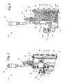
- the apparatus 10 shown in Figure 1 serves for applying fluids such as adhesive, in particular hot melt adhesive, to a substrate movable relative to the apparatus 10.
- the apparatus 10 includes an electropneumatically actuable application valve 14 connected to a main body 12.
- the main body 12 has an end face 13 at which the application valve 14 is arranged.
- the end face (see Figure 2 ) has an angled step 13' at which the application valve is arranged.
- a nozzle arrangement 18 is releasably fastened by means of screw connections 20 to a side 16 of the main body 12, that is opposite to the end face 13, and centered by means of pins 21 (see Figure 2 ).
- the nozzle arrangement has a mouthpiece 24 releasably connected to the nozzle arrangement 18.
- the apparatus 10 can be communicated with a fluid source (not shown) by means of a hose connection 22.
- the apparatus 10 further has a connecting element 26, by means of which electrical power can be fed to the apparatus 10.
- the apparatus 10 can be fixed in a position by means of fastening elements 28.
- the electrically actuable application valve 14 has an electrical connection 30 and a compressed air connection 32 shown in Figure 2 .
- a compressed air source (not shown) can be connected by means of the compressed air connection 32.
- the application valve 14 serves to selectively interrupt or enable the flow of fluid from the fluid source to the nozzle arrangement 18.
- the nozzle arrangement 18 has a nozzle opening 34 which in the selected embodiment is of a substantially slot-shaped configuration.
- a rotary grip 40 which permits displacement of the application pattern delivered by the applicator apparatus 10, on the substrate.
- the path in principle of the fluid can further be seen from Figure 2 .
- Fluid is fed to the apparatus 10 from the fluid source through the connection 22.
- the fluid flows through a feed passage 36 to the nozzle arrangement 18, wherein the feed passage 36 is selectively closed or opened by a valve body 38.
- the valve body 38 is moved by a valve needle 37.
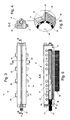
- the nozzle arrangement 18 is shown in Figure 3 .
- the fastening screws 20 extend through the nozzle opening 18 and project at a side 16' out of the nozzle arrangement 18 to come into engagement with screwthreads (not shown) in the main body 12.
- the pins 21 extend partially within the nozzle arrangement 18 and also project out of the opening 16' from the housing of the nozzle arrangement 18.
- the rotary grip 40 is arranged at the side 35 of the nozzle arrangement and is actuable by a hand of an operator.
- FIG. 4 corresponds to a section through the nozzle arrangement of Figure 3 along line C-C.
- a distributor passage 41 is disposed within the nozzle arrangement 18.
- the distributor passage 41 is substantially cylindrical and extends along a longitudinal axis 46 shown in the detail view in Figure 5 and Figure 6 .
- a movable body in the form of a hollow body 50 is mounted rotatably within the distributor passage 41.
- the hollow body 50 has a multiplicity of through passages 44 arranged along the periphery of the hollow body 50. It can further be seen that the nozzle opening 34 is in fluid-conducting communicating relationship by means of at least one outlet passage 48 with at least one through passage 44 as it is aligned with the nozzle opening 34 by means of rotation of the hollow body 50.
- the hollow body 50 is mounted rotatably about the longitudinal axis 46 of the distributor passage 41.
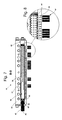
- Figure 6 is a cross-sectional view of the nozzle arrangement of Figure 3 along line A-A that fluid is fed to the hollow body 50 by means of a conduit 54.
- the fluid passes from the conduit 54 into an annular groove 52 arranged extending around the hollow body 50 and from which it passes from further conduits 55 (see Figure 7 ) into the interior 56 of the hollow body 50.
- the hollow body 50 has a plurality of rows of through passages 44 which are respectively arranged parallel to the longitudinal axis 46 on the periphery of the hollow body 50, the rows being respectively arranged in spaced relationship along the periphery of the hollow body 50.
- the hollow body 50 is arranged within the distributor passage 41 in such a way that the hollow body 50 is in sealing contact with a wall 62 of the distributor portion 41 at least partially in portions in which through passages extend. That prevents fluid from issuing.
- a sealing element 60 is arranged in a groove at the periphery of the hollow body 50, which prevents fluid from escaping from the housing from the side 35.
- Figure 7 shows a rotary position of the hollow body 50, that is changed in comparison with Figure 6 , this leading to a modified application pattern 58.
- Figure 8 in the selected rotary position of the hollow body 50 not all outlet passages 48 but only some thereof are communicated with the through passages 44 in such a way that fluid discharge is possible.
- the configuration of the application pattern 52 primarily depends on the axial arrangement of the through passages 44 at the hollow body 50 in the direction of the longitudinal axis 46 and the number of through passages 44 in a row.
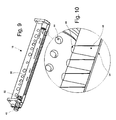
- FIG. 9 The view in Figure 9 with removed mouthpiece 24 (not shown) gives a three-dimensional view of the shape of the outlet passages 48.
- the outlet passages 48 have an inlet opening 47 which is identical in its width to the diameter of the through passages 44.
- the width of the outlet passage 48 increases linearly in the direction of flow of the fluid and it opens into the nozzle opening 34.
- the outlet passages 48 are markedly wider than they are deep and when the mouthpiece 24 is fitted assume a slot-shaped configuration.
- the exact dimensioning and configuration of the outlet passages 48 can vary according to the respective demand on the application pattern 52. Further influencing variables are the operating parameters of the fluid.
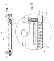
- Figures 11 and 12 show an alternative embodiment of a hollow body 50, which is not in the scope of the present invention.
- the through passages 44 in this embodiment are not in the form of simple bores but in the form of recesses with a substantially round through hole and a recess 64 in groove shape, extending parallel to the axis 46 (not shown) on the outside surface of the hollow body 50.
- the length of the groove 41 determines the number of outlet passages 48 which are supplied with fluid from the distributor passage 41.
Abstract
Description
- The present invention concerns an apparatus for applying fluids such as adhesive, in particular hot melt adhesive, to a substrate movable relative to the apparatus, comprising a main body having a feed passage connectable to a fluid source, an application valve for selectively interrupting or enabling the flow of fluid in the feed passage, and a nozzle arrangement having a distributor passage connectable to the feed passage and at least one nozzle opening communicating with the distributor passage for delivery of the fluid.
- Apparatuses of that kind are frequently also referred to as an application head and are used for example when substrates in film form or layer form are to be coated with fluid adhesive, for example hot melt adhesive, over a surface area thereof or in beads in order to produce given application patterns, for example shapes of the applied fluid. The fluid adhesive is usually stored in a fluid source such as a melting device. That fluid source is communicated with a main body of the apparatus by way of a hose connection. The fluid adhesive is conveyed by means of a conveyor means such as for example a pump into the apparatus and further conveyed through a distributor passage and in so doing passes a valve body of an application valve. The distributor passage communicates with a nozzle opening from which the adhesive is delivered and applied to a substrate. As the substrate is movable relative to the apparatus the fluid is applied to the substrate over the surface thereof. In known apparatuses of that kind the nozzle opening is typically in the form of an elongate slot. The length of the operative portion of the slot can be adjusted by a piston arranged movably in the longitudinal direction in the distributor passage. Such an apparatus is known for example from
DE 299 08 150 U . Apparatuses are also known with which adhesive beads or strips can be applied (seeDE 199 15 390 A , corresponding to the preamble of claim 1). - Some problems arise in operation of the known applicator apparatuses. Adjustment of the width of the area of the fluid to be applied is effected by a pushing or pulling movement of a piston in the distributor passage. While a pushing movement involves fluid being urged out of the nozzle arrangement in addition to the desired application thereof, air is sucked into the nozzle arrangement when the piston is performing a pulling movement. It is to be noted that when there is air in the nozzle the nozzle has to be vented before it can be brought into operation again. It is essentially a change in volume in the interior of the distributor passage, that is responsible for that adverse effect. A further disadvantage is that applicator apparatuses of the above-described kind occupy a comparatively large amount of space as, in addition to the space required by the apparatus itself, there must also be sufficient space at one side of the apparatus in order to be able to accommodate the piston in the condition of maximum extension thereof. That makes it difficult inter alia to arrange a plurality of applicator apparatuses in a row with each other at a small spacing in mutually juxtaposed relationship. In the industrial production of substrates to which a fluid is applied, that has the effect of increased manufacturing costs.
- Consequently an object of the invention is to provide an apparatus which as substantially as possible alleviates the disadvantages found in the state of the art and with which various application patterns can be produced in a simple fashion.
- The present invention attains that object by the features of claim 1. In an embodiment of the invention, a body is movable in the distributor passage and has through passages which can be selectively associated with the nozzle opening by means of movement of the body in such a way that fluid is passed out of the distributor passage into the nozzle opening through at least one through passage. It is thus easily possible to produce different application patterns, depending on the respective position of the movable body.
- The concept of the apparatus according to the invention makes use of the realisation that the application pattern which is produced by the apparatus and delivered to the substrate is afforded by a change in the association of through passages with the at least one nozzle opening. In that case the volume of the distributor passage in which fluid to be delivered is disposed remains substantially constant.
- That kind of movement of the body, i.e. rotational, means that no fluid is urged out of the nozzle arrangement or no air is sucked into the nozzle arrangement as the volume of the body in the distributor passage remains constant. Only the position of the openings is changed by the movement of the body.
- The body is a hollow body which is rotatable in the distributor passage and has radially arranged through passages which can be associated with the nozzle opening by means of rotation of the hollow body. The advantage of a rotatable hollow body in the distributor passage is in particular that it is possible to arrange on the periphery of the hollow body, a large number of different combinations of through passages which by rotation of the hollow body respectively cause a different width of application of fluid to the substrate and/or produce different application patterns. It is however immaterial how many different settings are provided in the hollow body for the necessary space that the applicator apparatus in accordance with this embodiment occupies.
- In accordance with the present invention a plurality of through passages are arranged in rows parallel to a longitudinal axis of the hollow body and extend through a peripheral surface of the hollow body. In that way it is possible to apply for example beads or strips. In this case the row is advantageously arranged on the periphery of the hollow body in such a way that, by rotation of the hollow body, all through passages of that row can be simultaneously aligned with the at least one nozzle opening so that fluid can be transferred from the distributor passage to the nozzle opening.
- In accordance with a further advantageous embodiment of the apparatus according to the invention a multiplicity of the rows formed by the through passages are respectively mutually spaced along the periphery of the hollow body. With such a selection for the arrangement of the through passages on the periphery of the hollow body, a respective given row of through passages can be aligned with the at least one nozzle opening by rotation of the hollow body into a respective given position.
- According to a preferred embodiment of the invention the rows formed by the through passages are arranged in mutually differing relationship in the hollow body in relation to the longitudinal axis thereof. The fact that the rows are arranged in mutually differing relationship on the periphery of the hollow body in the above-described manner means that, upon rotation of the hollow body, the position can be altered in relation to the longitudinal axis of the hollow body. In relation to the substrate which is movable relative to the apparatus, that means that the application position of the fluid to the substrate is variable by simply rotating the hollow body into another position.
- In accordance with the invention the rows of the through passages respectively have a different number of through passages and/or respectively involve a different spacing between the through passages. Such a configuration for the through passages on the hollow body makes it possible to provide a different configuration of through passages for each row of through passages and accordingly for each angular position of the hollow body. The consequence of this is that, in each angular position of the hollow body, in which a row of through passages is aligned with the at least one nozzle opening, it is possible to apply a specific application pattern linked thereto to the substrate. In that case, it is possible to switch over between different application patterns by simply rotating the hollow body.
- In accordance with a further advantageous embodiment of the present invention the through passages have an opening cross-section which is circular, elliptical, oval or polygonal, in particular rectangular. The choice of different geometries for the through passages makes it possible to take optimum account of different geometries of the at least one nozzle arrangement. Furthermore it is possible to specifically and targetedly influence the flow of material and the application image or pattern by the variation in the geometries. Furthermore in accordance with the above-described embodiment it is possible for the through passages to be in the form of slots so that, with a nozzle opening of a suitable configuration, it is possible for fluid to be applied to the substrate in an uninterrupted fashion over an area thereof.
- In accordance with a further embodiment of the present invention the hollow body is mounted in the distributor passage rotatably in such a way that in a respective angular position of the hollow body a through passage or a row of through passages which are arranged parallel to the longitudinal axis of the hollow body can be aligned with the at least one nozzle opening.
- In accordance with a further advantageous embodiment of the apparatus according to the invention the at least one nozzle opening is provided at the outlet end of an outlet passage in the form of a recess, in particular a milled-out recess, in the nozzle arrangement, and in particular is of a slot-shaped or round cross-section, wherein the outlet passage is adapted to connect the nozzle opening in fluid-conducting relationship with the distributor passage. Milling the outlet passage out of the body of the nozzle arrangement makes it possible to produce the outlet passages with a high degree of precision and repetition accuracy. That is advantageous in particular for a uniform precise discharge of fluid.
- According to the invention the outlet passages have an inlet of a width corresponding to the width of the through passages which can be associated therewith. Adapting the width of the outlet passage to the width of the feed passage which can be associated therewith provides that impairment of the flow of fluid at the transition between the through passage and the outlet passage is influenced or disturbed to a lesser degree than would be the case if the two passages were not matched to each other in their width.
- In a further advantageous embodiment of the apparatus according to the invention the at least one outlet passage is of a polygonal, in particular rectangular or trapezoidal longitudinal cross-section. A configuration for the outlet passage, in which there is an increasing and/or decreasing passage width in the longitudinal direction of the outlet passage, can be advantageous for influencing the discharge performance of the fluid, in particular the discharge speed and the form of flow thereof. The precise configuration of the outlet passage depends on the respective individual case, in particular the fluid to be used and operating parameters such as for example viscosity, temperature and pressure.
- In accordance with a further advantageous embodiment of the present invention the body can be arrested in a predetermined angular position in force-locking or positively locking relationship, in particular by means of a clamping screw or a latching means. Advantageously such arrestability is to be provided for precisely the angular positions in which a respective row of through passages is oriented in aligned relationship with the at least one nozzle opening. Such an arresting capability prevents unintentional displacement of the hollow body, which could lead to unwanted changes in the application pattern. Clamping devices such as for example clamping screws are to be considered as an arresting means having a force-locking action. Various latching means appear appropriate to provide a positively locking arresting effect. They can include for example spring-assisted mechanisms such as resilient pressure portions.
- In accordance with a further embodiment of the present invention it has a rotary grip which is non-rotatably connected to an end portion of the body and which extends outside the nozzle arrangement. Actuation of the rotary grip makes it possible to manually adjust the desired application pattern by means of rotation of the hollow body. In addition, as an alternative to displacement of the hollow body by manual rotation of the rotary grip, it is possible to fit a motor drive for the hollow body, which either externally co-operates with the rotary grip or can be disposed within the housing of the apparatus according to the invention. The transmission of force from such a motor drive to the hollow body can be effected for example by way of a gear transmission and/or a belt drive.
- In a further advantageous embodiment of the apparatus according to the invention a peripheral surface or a peripheral surface composite of the rotary grip is roughened. Roughening at least a part of the surface of the rotary grip contributes to the operator having a better hold on the rotary grip. Operability of the apparatus is decisively improved in that case. In that respect the rotary grip can be of a substantially cylindrical configuration or as a departure therefrom may be of a non-circular cross-sectional area, being for example of a polygonal or stellate cross-sectional shape.
- In accordance with a further embodiment of the present invention the nozzle arrangement has a mouthpiece which is connectable to the nozzle arrangement and can be associated with a portion of the nozzle arrangement, in which the at least one outlet passage and the at least one nozzle opening are arranged. The mouthpiece is preferably connected to the nozzle arrangement by way of fastening means and is of an area which is so arranged at the nozzle arrangement that it delimits the outlet cross-section of the at least one nozzle opening. Advantageously the mouthpiece can be connected to the nozzle arrangement in such a way that it is releasable therefrom with a few manipulation operations in order to be able to clean the at least one nozzle opening and the at least one outlet passage and/or the nozzle arrangement overall. The fact that cleaning of the nozzle arrangement can be effected without the entire apparatus having to be dismantled, but only the mouthpiece, means that the outage and maintenance times in operation of the apparatus according to the invention can be reduced.
- In accordance with a further advantageous embodiment of the apparatus according to the invention the fluid is fed to the hollow body by means of a peripherally extending recess, in particular an annular groove, which is provided in the peripheral surface of the hollow body, wherein at least one conduit extends from the recess into the interior of the hollow body. A feed of fluid into the interior of the hollow body is possible in any angular position of the hollow body by means of the annular groove.
- In accordance with a further advantageous embodiment of the apparatus according to the invention an outside wall of the hollow body at least in portions in which through passages extend can be brought into substantially sealing contact with a wall of the distributor passage. That ensures that fluid which has been fed to the interior of the hollow body can pass into the at least one outlet passage exclusively through the through passages. Unwanted issue of fluid from leaks or leaking locations is avoided in that way so that the risk of the apparatus being clogged and contaminated with adhesive is reduced.
- The invention is described in greater detail hereinafter by means of preferred embodiments by way of example of the apparatus according to the invention for applying fluids such as adhesive, in particular hot melt adhesive, to a substrate movable relative to the apparatus, and with reference to the accompanying drawings in which:
-
Figure 1 shows a perspective external view of an adhesive applicator apparatus according to the invention, -
Figure 2 shows a partly cross-sectional side view of the apparatus ofFigure 1 , -
Figure 3 shows a side view from below of a nozzle arrangement, -
Figure 4 shows a cross-sectional view of the nozzle arrangement ofFigure 3 , -
Figure 5 shows a detail view from the view ofFigure 4 , -
Figure 6 shows a further cross-sectional view of the nozzle arrangement ofFigures 3 through 5 , -
Figure 7 shows a further cross-sectional view of the nozzle arrangement ofFigures 3 through 6 with an alternative operating position of the hollow body, -
Figure 8 shows a detail view from the view ofFigure 7 , -
Figure 9 shows a perspective view of a nozzle arrangement with removed mouthpiece, -
Figure 10 shows a detail view from the view ofFigure 9 , -
Figure 11 shows a perspective view of a nozzle arrangement outside the scope of the present invention with an alternative hollow body and removed mouthpiece, and -
Figure 12 shows a detail view from the view ofFigure 11 . - The
apparatus 10 shown inFigure 1 serves for applying fluids such as adhesive, in particular hot melt adhesive, to a substrate movable relative to theapparatus 10. Theapparatus 10 includes an electropneumatically actuableapplication valve 14 connected to amain body 12. Themain body 12 has anend face 13 at which theapplication valve 14 is arranged. In this case the end face (seeFigure 2 ) has an angled step 13' at which the application valve is arranged. - A
nozzle arrangement 18 is releasably fastened by means ofscrew connections 20 to aside 16 of themain body 12, that is opposite to theend face 13, and centered by means of pins 21 (seeFigure 2 ). The nozzle arrangement has a mouthpiece 24 releasably connected to thenozzle arrangement 18. Theapparatus 10 can be communicated with a fluid source (not shown) by means of ahose connection 22. Theapparatus 10 further has a connectingelement 26, by means of which electrical power can be fed to theapparatus 10. Theapparatus 10 can be fixed in a position by means offastening elements 28. - The electrically
actuable application valve 14 has anelectrical connection 30 and acompressed air connection 32 shown inFigure 2 . A compressed air source (not shown) can be connected by means of thecompressed air connection 32. Theapplication valve 14 serves to selectively interrupt or enable the flow of fluid from the fluid source to thenozzle arrangement 18. - As can be seen from
Figures 1 and 2 thenozzle arrangement 18 has anozzle opening 34 which in the selected embodiment is of a substantially slot-shaped configuration. In addition disposed at aside 35 of thenozzle arrangement 18 is arotary grip 40 which permits displacement of the application pattern delivered by theapplicator apparatus 10, on the substrate. The path in principle of the fluid can further be seen fromFigure 2 . Fluid is fed to theapparatus 10 from the fluid source through theconnection 22. The fluid flows through afeed passage 36 to thenozzle arrangement 18, wherein thefeed passage 36 is selectively closed or opened by avalve body 38. Thevalve body 38 is moved by avalve needle 37. - The
nozzle arrangement 18 is shown inFigure 3 . The fastening screws 20 extend through thenozzle opening 18 and project at a side 16' out of thenozzle arrangement 18 to come into engagement with screwthreads (not shown) in themain body 12. Thepins 21 extend partially within thenozzle arrangement 18 and also project out of the opening 16' from the housing of thenozzle arrangement 18. Therotary grip 40 is arranged at theside 35 of the nozzle arrangement and is actuable by a hand of an operator. - The cross-sectional view in
Figure 4 corresponds to a section through the nozzle arrangement ofFigure 3 along line C-C. Adistributor passage 41 is disposed within thenozzle arrangement 18. Thedistributor passage 41 is substantially cylindrical and extends along alongitudinal axis 46 shown in the detail view inFigure 5 and Figure 6 . - As can further be seen from
Figure 5 a movable body in the form of ahollow body 50 is mounted rotatably within thedistributor passage 41. Thehollow body 50 has a multiplicity of throughpassages 44 arranged along the periphery of thehollow body 50. It can further be seen that thenozzle opening 34 is in fluid-conducting communicating relationship by means of at least oneoutlet passage 48 with at least one throughpassage 44 as it is aligned with thenozzle opening 34 by means of rotation of thehollow body 50. Thehollow body 50 is mounted rotatably about thelongitudinal axis 46 of thedistributor passage 41. - It will be seen from
Figure 6 which is a cross-sectional view of the nozzle arrangement ofFigure 3 along line A-A that fluid is fed to thehollow body 50 by means of a conduit 54. The fluid passes from the conduit 54 into anannular groove 52 arranged extending around thehollow body 50 and from which it passes from further conduits 55 (seeFigure 7 ) into the interior 56 of thehollow body 50. As is further clearly shown inFigure 6 thehollow body 50 has a plurality of rows of throughpassages 44 which are respectively arranged parallel to thelongitudinal axis 46 on the periphery of thehollow body 50, the rows being respectively arranged in spaced relationship along the periphery of thehollow body 50. In that way, by rotary movement of thehollow body 50 at therotary grip 40, a respective row with throughpassages 44 can be so associated in thedistributor passage 41 that the throughpassages 44 are in aligned and fluid-conducting communicating relationship with theoutlet passages 48. When the outlet passages are aligned with throughpassages 44 as shown inFigure 6 , fluid can be discharged from theapparatus 10 on to a substrate. That affords an application pattern 58. - The
hollow body 50 is arranged within thedistributor passage 41 in such a way that thehollow body 50 is in sealing contact with awall 62 of thedistributor portion 41 at least partially in portions in which through passages extend. That prevents fluid from issuing. In addition a sealingelement 60 is arranged in a groove at the periphery of thehollow body 50, which prevents fluid from escaping from the housing from theside 35. - As shown in
Figure 7 the number and arrangement of the throughpassages 44 which are aligned withoutlet passages 48 can be altered by rotary movement of thehollow body 50.Figure 7 shows a rotary position of thehollow body 50, that is changed in comparison withFigure 6 , this leading to a modified application pattern 58. As can be seen in particular fromFigure 8 in the selected rotary position of thehollow body 50 not alloutlet passages 48 but only some thereof are communicated with the throughpassages 44 in such a way that fluid discharge is possible. In this case the configuration of theapplication pattern 52 primarily depends on the axial arrangement of the throughpassages 44 at thehollow body 50 in the direction of thelongitudinal axis 46 and the number of throughpassages 44 in a row. - The view in
Figure 9 with removed mouthpiece 24 (not shown) gives a three-dimensional view of the shape of theoutlet passages 48. It can be seen in particular fromFigure 10 that theoutlet passages 48 have an inlet opening 47 which is identical in its width to the diameter of the throughpassages 44. The width of theoutlet passage 48 increases linearly in the direction of flow of the fluid and it opens into thenozzle opening 34. In this case theoutlet passages 48 are markedly wider than they are deep and when the mouthpiece 24 is fitted assume a slot-shaped configuration. The exact dimensioning and configuration of theoutlet passages 48 can vary according to the respective demand on theapplication pattern 52. Further influencing variables are the operating parameters of the fluid. -
Figures 11 and 12 show an alternative embodiment of ahollow body 50, which is not in the scope of the present invention. As can be seen in particular fromFigure 12 the throughpassages 44 in this embodiment are not in the form of simple bores but in the form of recesses with a substantially round through hole and arecess 64 in groove shape, extending parallel to the axis 46 (not shown) on the outside surface of thehollow body 50. In this case the length of thegroove 41 determines the number ofoutlet passages 48 which are supplied with fluid from thedistributor passage 41.
Claims (13)
- Apparatus (10) for applying fluids such as adhesive, in particular hot melt adhesive, to a substrate movable relative to the apparatus, comprising
a main body (12) having a feed passage connectable to a fluid source,
an application valve (14) for selectively interrupting or enabling the flow of fluid in the feed passage, and a distributor passage connectable to the feed
a nozzle arrangement (18) having a distributor passage connectable to the feed passage and at least one nozzle opening communicating with the distributor passage for delivery of the fluid,
characterised by a hollow body (50) which is rotatable in the distributor passage (41) and has radially arranged a plurality of through passages (44) which can be associated with the nozzle opening (34) by means of rotation of the hollow body in such a way that fluid is passed out of the distributor passage into the nozzle opening (34) through said through passages (44) and through outlet passages (48), when said outlet passages (48) are aligned with said through passages (44),
wherein said through passages (44) are arranged in rows parallel to a longitudinal axis of the hollow body (50) and extend through a peripheral surface of the hollow body, wherein the rows of the through passages (44) respectively have a different number of through passages (44) and/or respectively involve a different spacing between the through passages (44) and
wherein said outlet passages have an inlet of a width corresponding to the width of the through passages (44) which can be associated therewith. - Apparatus as set forth in claim 1 characterised in that a multiplicity of the rows formed by the through passages (44) are respectively mutually spaced along the periphery of the hollow body (50).
- Apparatus as set forth in claim 1 or claim 2 characterised in that the rows formed by the through passages (44) are arranged in mutually differing relationship in the hollow body (50) in relation to the longitudinal axis thereof.
- Apparatus as set forth in one of the preceding claims characterised in that the through passages (44) have an opening cross-section which is circular, elliptical, oval or polygonal, in particular rectangular.
- Apparatus as set forth in one of preceding claims characterised in that the hollow body (50) is mounted in the distributor passage (41) rotatably in such a way that in a respective angular position of the hollow body a through passage (44) or a row of through passages which are arranged parallel to the longitudinal axis of the hollow body can be aligned with at least one nozzle opening (34).
- Apparatus as set forth in one of the preceding claims characterised in that the at least one nozzle opening (34) is provided at the outlet end of an outlet passage (44) in the form of a recess, in particular a milled-out recess, in the nozzle arrangement, and
in particular is of a slot-shaped or round cross-section, wherein the outlet passage is adapted to connect the nozzle opening in fluid-conducting relationship with the distributor passage. - Apparatus as set forth in one of the preceding claims characterised in that the at least one outlet passage (48) is of a polygonal, in particular rectangular or trapezoidal longitudinal cross-section.
- Apparatus as set forth in one of the preceding claims characterised in that the main body (12) can be arrested in a predetermined angular position in force-locking or positively locking relationship, in particular by means of a clamping screw or a latching means.
- Apparatus as set forth in one of the preceding claims characterised by a rotary grip (40) which is non-rotatably connected to an end portion of the main body (12) and which extends outside the nozzle arrangement (18).
- Apparatus as set forth in claim 9 characterised in that a peripheral surface or a peripheral surface composite of the rotary grip (40) is roughened.
- Apparatus as set forth in one of the preceding claims characterised in that the nozzle arrangement (18) has a mouthpiece which is connectable to the nozzle arrangement and can be associated with a portion of the nozzle arrangement, in which the at least one outlet passage and the at least one nozzle opening (34) are arranged.
- Apparatus as set forth in one of the preceding claims characterised in that the fluid is fed to the hollow body (50) by means of a peripherally extending recess, in particular an annular groove, which is provided in the peripheral surface of the hollow body, wherein at least one conduit extends from the recess into the interior of the hollow body.
- Apparatus as set forth in one of the preceding claims characterised in that an outside wall of the hollow body (50) at least in portions in which through passages (44) extend can be brought into substantially sealing contact with a wall of the distributor passage.
Applications Claiming Priority (1)
| Application Number | Priority Date | Filing Date | Title |
|---|---|---|---|
| DE102008047266A DE102008047266A1 (en) | 2008-09-12 | 2008-09-12 | Device for applying fluids |
Publications (2)
| Publication Number | Publication Date |
|---|---|
| EP2163313A1 EP2163313A1 (en) | 2010-03-17 |
| EP2163313B1 true EP2163313B1 (en) | 2012-03-28 |
Family
ID=41064638
Family Applications (1)
| Application Number | Title | Priority Date | Filing Date |
|---|---|---|---|
| EP09168183A Not-in-force EP2163313B1 (en) | 2008-09-12 | 2009-08-19 | Apparatus for applying fluids |
Country Status (7)
| Country | Link |
|---|---|
| US (1) | US8453596B2 (en) |
| EP (1) | EP2163313B1 (en) |
| JP (1) | JP5692978B2 (en) |
| CN (1) | CN101670328A (en) |
| AT (1) | ATE551125T1 (en) |
| DE (1) | DE102008047266A1 (en) |
| ES (1) | ES2384018T3 (en) |
Families Citing this family (9)
| Publication number | Priority date | Publication date | Assignee | Title |
|---|---|---|---|---|
| US20120027953A1 (en) * | 2010-07-28 | 2012-02-02 | Synos Technology, Inc. | Rotating Reactor Assembly for Depositing Film on Substrate |
| DE102011004232B4 (en) * | 2011-02-16 | 2024-04-18 | Ecoclean Gmbh | Nozzle module and cleaning device with nozzle module |
| DE102013208399A1 (en) * | 2013-05-07 | 2014-11-13 | Hauni Maschinenbau Ag | Device for applying a glue trace to a wrapping strip of a rod-shaped product of the tobacco-processing industry |
| DE102014007425B4 (en) * | 2014-05-22 | 2019-05-23 | Illinois Tool Works Inc. | Apparatus and method for applying a hotmelt adhesive to a substrate |
| WO2017177049A1 (en) * | 2016-04-06 | 2017-10-12 | Glas-Weld Systems, Inc. | Windshield and laminated glass repair tool |
| DE102017112892A1 (en) * | 2017-06-12 | 2018-12-13 | Atlas Copco Ias Gmbh | applicator |
| EP3608028B1 (en) * | 2018-08-06 | 2020-12-23 | VARTA Microbattery GmbH | Slit valve, coating installation and coating method |
| KR102035978B1 (en) * | 2019-06-07 | 2019-10-23 | 최동수 | Apparatus and method for applying adhesive of synthetic resin film |
| CN112170049A (en) * | 2020-09-24 | 2021-01-05 | 冯夏莲 | Machine part painting equipment |
Family Cites Families (19)
| Publication number | Priority date | Publication date | Assignee | Title |
|---|---|---|---|---|
| US2827928A (en) * | 1954-10-11 | 1958-03-25 | Dole Eng Co James | Filling apparatus |
| US3182867A (en) * | 1963-11-18 | 1965-05-11 | Walker Mfg Co | Dispensing mechanism |
| JPS4734109U (en) * | 1972-04-22 | 1972-12-16 | ||
| DE2409544A1 (en) * | 1973-03-01 | 1974-09-12 | Nippon Steel Corp | DEVICE FOR SPRAYING A FLOWABLE MEDIUM |
| JPS5019008A (en) * | 1973-06-20 | 1975-02-28 | ||
| JPS5221305Y2 (en) * | 1973-05-31 | 1977-05-16 | ||
| US4451414A (en) * | 1982-06-28 | 1984-05-29 | Welding Engineers, Inc. | Apparatus and method for controlling extrusion back pressure utilizing a single sleeve die |
| US4510784A (en) * | 1983-10-11 | 1985-04-16 | Kaiser Aluminum & Chemical Corporation | Rolling mill spray bar |
| US4667879A (en) * | 1985-08-21 | 1987-05-26 | Nordson Corporation | Thermoplastic material applicator having an adjustable slot nozzle |
| US4628961A (en) * | 1985-09-19 | 1986-12-16 | Lew Hyok S | Multiple orifice stepper control valve |
| JP3021838B2 (en) * | 1991-09-24 | 2000-03-15 | 三菱化学株式会社 | Coating head |
| JPH09327645A (en) * | 1996-06-10 | 1997-12-22 | Kiroku Kobayashi | Jet nozzle device for coating highly viscous coating material |
| US6464785B1 (en) * | 1997-12-22 | 2002-10-15 | Wolfgang Puffe | Rotary applicator head |
| DE19854634C1 (en) * | 1998-11-26 | 2000-02-24 | Wolfgang Puffe | Contactless application of a fluid, especially a thermoplastic or molten hot melt adhesive, onto a moving strip and applying head with a housing containing a chamber and a rotating roll slide |
| DE19915390C2 (en) * | 1999-04-06 | 2003-04-03 | Wolfgang Puffe | Method and device for spraying melted hot-melt adhesive or liquefied thermoplastic |
| DE29908150U1 (en) | 1999-05-10 | 1999-08-05 | Nordson Corp | Fluid application device |
| DE10306884B3 (en) * | 2003-02-18 | 2004-06-03 | Wolfgang Puffe | Glue applicator head for hot-melt glue has longitudinal groove either connected to or cut off from outlet borings, depending on rotary position of roll slide |
| DE102004034422B4 (en) * | 2004-07-15 | 2006-12-28 | Nordson Corp., Westlake | Application head with spring block supported in the housing |
| DE102004058542A1 (en) * | 2004-12-03 | 2006-06-08 | Nordson Corporation, Westlake | Rotary applicator head and label applicator for applying labels |
-
2008
- 2008-09-12 DE DE102008047266A patent/DE102008047266A1/en not_active Withdrawn
-
2009
- 2009-08-19 ES ES09168183T patent/ES2384018T3/en active Active
- 2009-08-19 AT AT09168183T patent/ATE551125T1/en active
- 2009-08-19 EP EP09168183A patent/EP2163313B1/en not_active Not-in-force
- 2009-09-10 US US12/556,807 patent/US8453596B2/en not_active Expired - Fee Related
- 2009-09-11 JP JP2009210100A patent/JP5692978B2/en not_active Expired - Fee Related
- 2009-09-14 CN CN200910173177A patent/CN101670328A/en active Pending
Also Published As
| Publication number | Publication date |
|---|---|
| EP2163313A1 (en) | 2010-03-17 |
| DE102008047266A1 (en) | 2010-04-15 |
| US20100064967A1 (en) | 2010-03-18 |
| ATE551125T1 (en) | 2012-04-15 |
| US8453596B2 (en) | 2013-06-04 |
| JP2010064069A (en) | 2010-03-25 |
| ES2384018T3 (en) | 2012-06-28 |
| JP5692978B2 (en) | 2015-04-01 |
| CN101670328A (en) | 2010-03-17 |
Similar Documents
| Publication | Publication Date | Title |
|---|---|---|
| EP2163313B1 (en) | Apparatus for applying fluids | |
| US6296463B1 (en) | Segmented metering die for hot melt adhesives or other polymer melts | |
| EP3880435B1 (en) | Additive manufacturing system and corresponding components for elastomeric materials | |
| US10150134B2 (en) | Liquid dispensing applicators having backpressure control devices, and related methods | |
| US10610882B2 (en) | Applicator with diverter plate | |
| US5620139A (en) | Nozzle adapter with recirculation valve | |
| KR101317734B1 (en) | Liquid material ejector | |
| US6705537B2 (en) | Orbital applicator tool with self-centering dispersing head | |
| WO2010050127A1 (en) | Nozzle with replacement function, nozzle device with replacement function, and application device with nozzle device with replacement function | |
| US6827777B2 (en) | Rotary application head | |
| EP1424140A1 (en) | Metered liquid dispensing system | |
| JP2005313170A (en) | Liquid dispenser having individualized process air control part | |
| EP0216199B1 (en) | Multi-orifice zero cavity nozzle dispenser | |
| JP5582679B2 (en) | Apparatus having a slot nozzle assembly for dispensing fluid | |
| JP3670390B2 (en) | Slot nozzle | |
| CN107835718B (en) | Coating agent valve | |
| EP1902787B1 (en) | Apparatus for applying fluids such as adhesive, in particular hot melt adhesive | |
| JPH105662A (en) | Die coater | |
| JP3398035B2 (en) | Needleless two-liquid concentric nozzle spray gun | |
| CN210098002U (en) | Spray gun |
Legal Events
| Date | Code | Title | Description |
|---|---|---|---|
| PUAI | Public reference made under article 153(3) epc to a published international application that has entered the european phase |
Free format text: ORIGINAL CODE: 0009012 |
|
| AK | Designated contracting states |
Kind code of ref document: A1 Designated state(s): AT BE BG CH CY CZ DE DK EE ES FI FR GB GR HR HU IE IS IT LI LT LU LV MC MK MT NL NO PL PT RO SE SI SK SM TR |
|
| AX | Request for extension of the european patent |
Extension state: AL BA RS |
|
| 17P | Request for examination filed |
Effective date: 20100917 |
|
| 17Q | First examination report despatched |
Effective date: 20101012 |
|
| GRAP | Despatch of communication of intention to grant a patent |
Free format text: ORIGINAL CODE: EPIDOSNIGR1 |
|
| RIC1 | Information provided on ipc code assigned before grant |
Ipc: B05C 5/02 20060101AFI20110913BHEP |
|
| GRAS | Grant fee paid |
Free format text: ORIGINAL CODE: EPIDOSNIGR3 |
|
| GRAA | (expected) grant |
Free format text: ORIGINAL CODE: 0009210 |
|
| AK | Designated contracting states |
Kind code of ref document: B1 Designated state(s): AT BE BG CH CY CZ DE DK EE ES FI FR GB GR HR HU IE IS IT LI LT LU LV MC MK MT NL NO PL PT RO SE SI SK SM TR |
|
| REG | Reference to a national code |
Ref country code: GB Ref legal event code: FG4D |
|
| REG | Reference to a national code |
Ref country code: CH Ref legal event code: EP |
|
| REG | Reference to a national code |
Ref country code: AT Ref legal event code: REF Ref document number: 551125 Country of ref document: AT Kind code of ref document: T Effective date: 20120415 |
|
| REG | Reference to a national code |
Ref country code: IE Ref legal event code: FG4D |
|
| REG | Reference to a national code |
Ref country code: DE Ref legal event code: R096 Ref document number: 602009006096 Country of ref document: DE Effective date: 20120524 |
|
| REG | Reference to a national code |
Ref country code: ES Ref legal event code: FG2A Ref document number: 2384018 Country of ref document: ES Kind code of ref document: T3 Effective date: 20120628 |
|
| REG | Reference to a national code |
Ref country code: NL Ref legal event code: VDEP Effective date: 20120328 |
|
| PG25 | Lapsed in a contracting state [announced via postgrant information from national office to epo] |
Ref country code: NO Free format text: LAPSE BECAUSE OF FAILURE TO SUBMIT A TRANSLATION OF THE DESCRIPTION OR TO PAY THE FEE WITHIN THE PRESCRIBED TIME-LIMIT Effective date: 20120628 Ref country code: LT Free format text: LAPSE BECAUSE OF FAILURE TO SUBMIT A TRANSLATION OF THE DESCRIPTION OR TO PAY THE FEE WITHIN THE PRESCRIBED TIME-LIMIT Effective date: 20120328 Ref country code: HR Free format text: LAPSE BECAUSE OF FAILURE TO SUBMIT A TRANSLATION OF THE DESCRIPTION OR TO PAY THE FEE WITHIN THE PRESCRIBED TIME-LIMIT Effective date: 20120328 |
|
| LTIE | Lt: invalidation of european patent or patent extension |
Effective date: 20120328 |
|
| PG25 | Lapsed in a contracting state [announced via postgrant information from national office to epo] |
Ref country code: LV Free format text: LAPSE BECAUSE OF FAILURE TO SUBMIT A TRANSLATION OF THE DESCRIPTION OR TO PAY THE FEE WITHIN THE PRESCRIBED TIME-LIMIT Effective date: 20120328 Ref country code: GR Free format text: LAPSE BECAUSE OF FAILURE TO SUBMIT A TRANSLATION OF THE DESCRIPTION OR TO PAY THE FEE WITHIN THE PRESCRIBED TIME-LIMIT Effective date: 20120629 Ref country code: FI Free format text: LAPSE BECAUSE OF FAILURE TO SUBMIT A TRANSLATION OF THE DESCRIPTION OR TO PAY THE FEE WITHIN THE PRESCRIBED TIME-LIMIT Effective date: 20120328 |
|
| REG | Reference to a national code |
Ref country code: AT Ref legal event code: MK05 Ref document number: 551125 Country of ref document: AT Kind code of ref document: T Effective date: 20120328 |
|
| PG25 | Lapsed in a contracting state [announced via postgrant information from national office to epo] |
Ref country code: CY Free format text: LAPSE BECAUSE OF FAILURE TO SUBMIT A TRANSLATION OF THE DESCRIPTION OR TO PAY THE FEE WITHIN THE PRESCRIBED TIME-LIMIT Effective date: 20120328 |
|
| PG25 | Lapsed in a contracting state [announced via postgrant information from national office to epo] |
Ref country code: SE Free format text: LAPSE BECAUSE OF FAILURE TO SUBMIT A TRANSLATION OF THE DESCRIPTION OR TO PAY THE FEE WITHIN THE PRESCRIBED TIME-LIMIT Effective date: 20120328 Ref country code: CZ Free format text: LAPSE BECAUSE OF FAILURE TO SUBMIT A TRANSLATION OF THE DESCRIPTION OR TO PAY THE FEE WITHIN THE PRESCRIBED TIME-LIMIT Effective date: 20120328 Ref country code: SI Free format text: LAPSE BECAUSE OF FAILURE TO SUBMIT A TRANSLATION OF THE DESCRIPTION OR TO PAY THE FEE WITHIN THE PRESCRIBED TIME-LIMIT Effective date: 20120328 Ref country code: PL Free format text: LAPSE BECAUSE OF FAILURE TO SUBMIT A TRANSLATION OF THE DESCRIPTION OR TO PAY THE FEE WITHIN THE PRESCRIBED TIME-LIMIT Effective date: 20120328 Ref country code: RO Free format text: LAPSE BECAUSE OF FAILURE TO SUBMIT A TRANSLATION OF THE DESCRIPTION OR TO PAY THE FEE WITHIN THE PRESCRIBED TIME-LIMIT Effective date: 20120328 Ref country code: BE Free format text: LAPSE BECAUSE OF FAILURE TO SUBMIT A TRANSLATION OF THE DESCRIPTION OR TO PAY THE FEE WITHIN THE PRESCRIBED TIME-LIMIT Effective date: 20120328 Ref country code: EE Free format text: LAPSE BECAUSE OF FAILURE TO SUBMIT A TRANSLATION OF THE DESCRIPTION OR TO PAY THE FEE WITHIN THE PRESCRIBED TIME-LIMIT Effective date: 20120328 Ref country code: IS Free format text: LAPSE BECAUSE OF FAILURE TO SUBMIT A TRANSLATION OF THE DESCRIPTION OR TO PAY THE FEE WITHIN THE PRESCRIBED TIME-LIMIT Effective date: 20120728 |
|
| PG25 | Lapsed in a contracting state [announced via postgrant information from national office to epo] |
Ref country code: PT Free format text: LAPSE BECAUSE OF FAILURE TO SUBMIT A TRANSLATION OF THE DESCRIPTION OR TO PAY THE FEE WITHIN THE PRESCRIBED TIME-LIMIT Effective date: 20120730 Ref country code: SK Free format text: LAPSE BECAUSE OF FAILURE TO SUBMIT A TRANSLATION OF THE DESCRIPTION OR TO PAY THE FEE WITHIN THE PRESCRIBED TIME-LIMIT Effective date: 20120328 |
|
| PG25 | Lapsed in a contracting state [announced via postgrant information from national office to epo] |
Ref country code: AT Free format text: LAPSE BECAUSE OF FAILURE TO SUBMIT A TRANSLATION OF THE DESCRIPTION OR TO PAY THE FEE WITHIN THE PRESCRIBED TIME-LIMIT Effective date: 20120328 Ref country code: NL Free format text: LAPSE BECAUSE OF FAILURE TO SUBMIT A TRANSLATION OF THE DESCRIPTION OR TO PAY THE FEE WITHIN THE PRESCRIBED TIME-LIMIT Effective date: 20120328 Ref country code: DK Free format text: LAPSE BECAUSE OF FAILURE TO SUBMIT A TRANSLATION OF THE DESCRIPTION OR TO PAY THE FEE WITHIN THE PRESCRIBED TIME-LIMIT Effective date: 20120328 |
|
| PLBE | No opposition filed within time limit |
Free format text: ORIGINAL CODE: 0009261 |
|
| STAA | Information on the status of an ep patent application or granted ep patent |
Free format text: STATUS: NO OPPOSITION FILED WITHIN TIME LIMIT |
|
| 26N | No opposition filed |
Effective date: 20130103 |
|
| PG25 | Lapsed in a contracting state [announced via postgrant information from national office to epo] |
Ref country code: MC Free format text: LAPSE BECAUSE OF NON-PAYMENT OF DUE FEES Effective date: 20120831 |
|
| REG | Reference to a national code |
Ref country code: DE Ref legal event code: R097 Ref document number: 602009006096 Country of ref document: DE Effective date: 20130103 |
|
| REG | Reference to a national code |
Ref country code: FR Ref legal event code: ST Effective date: 20130430 |
|
| REG | Reference to a national code |
Ref country code: IE Ref legal event code: MM4A |
|
| PG25 | Lapsed in a contracting state [announced via postgrant information from national office to epo] |
Ref country code: BG Free format text: LAPSE BECAUSE OF FAILURE TO SUBMIT A TRANSLATION OF THE DESCRIPTION OR TO PAY THE FEE WITHIN THE PRESCRIBED TIME-LIMIT Effective date: 20120628 Ref country code: IE Free format text: LAPSE BECAUSE OF NON-PAYMENT OF DUE FEES Effective date: 20120819 |
|
| PG25 | Lapsed in a contracting state [announced via postgrant information from national office to epo] |
Ref country code: FR Free format text: LAPSE BECAUSE OF NON-PAYMENT OF DUE FEES Effective date: 20120831 |
|
| PG25 | Lapsed in a contracting state [announced via postgrant information from national office to epo] |
Ref country code: MT Free format text: LAPSE BECAUSE OF FAILURE TO SUBMIT A TRANSLATION OF THE DESCRIPTION OR TO PAY THE FEE WITHIN THE PRESCRIBED TIME-LIMIT Effective date: 20120328 |
|
| REG | Reference to a national code |
Ref country code: CH Ref legal event code: PL |
|
| PG25 | Lapsed in a contracting state [announced via postgrant information from national office to epo] |
Ref country code: CH Free format text: LAPSE BECAUSE OF NON-PAYMENT OF DUE FEES Effective date: 20130831 Ref country code: LI Free format text: LAPSE BECAUSE OF NON-PAYMENT OF DUE FEES Effective date: 20130831 Ref country code: TR Free format text: LAPSE BECAUSE OF FAILURE TO SUBMIT A TRANSLATION OF THE DESCRIPTION OR TO PAY THE FEE WITHIN THE PRESCRIBED TIME-LIMIT Effective date: 20120328 |
|
| PG25 | Lapsed in a contracting state [announced via postgrant information from national office to epo] |
Ref country code: LU Free format text: LAPSE BECAUSE OF NON-PAYMENT OF DUE FEES Effective date: 20120819 Ref country code: SM Free format text: LAPSE BECAUSE OF FAILURE TO SUBMIT A TRANSLATION OF THE DESCRIPTION OR TO PAY THE FEE WITHIN THE PRESCRIBED TIME-LIMIT Effective date: 20120328 |
|
| PG25 | Lapsed in a contracting state [announced via postgrant information from national office to epo] |
Ref country code: HU Free format text: LAPSE BECAUSE OF FAILURE TO SUBMIT A TRANSLATION OF THE DESCRIPTION OR TO PAY THE FEE WITHIN THE PRESCRIBED TIME-LIMIT Effective date: 20090819 |
|
| PG25 | Lapsed in a contracting state [announced via postgrant information from national office to epo] |
Ref country code: MK Free format text: LAPSE BECAUSE OF FAILURE TO SUBMIT A TRANSLATION OF THE DESCRIPTION OR TO PAY THE FEE WITHIN THE PRESCRIBED TIME-LIMIT Effective date: 20120328 |
|
| PGFP | Annual fee paid to national office [announced via postgrant information from national office to epo] |
Ref country code: GB Payment date: 20150819 Year of fee payment: 7 |
|
| GBPC | Gb: european patent ceased through non-payment of renewal fee |
Effective date: 20160819 |
|
| PG25 | Lapsed in a contracting state [announced via postgrant information from national office to epo] |
Ref country code: GB Free format text: LAPSE BECAUSE OF NON-PAYMENT OF DUE FEES Effective date: 20160819 |
|
| PGFP | Annual fee paid to national office [announced via postgrant information from national office to epo] |
Ref country code: DE Payment date: 20180823 Year of fee payment: 10 Ref country code: ES Payment date: 20180921 Year of fee payment: 10 Ref country code: IT Payment date: 20180830 Year of fee payment: 10 |
|
| REG | Reference to a national code |
Ref country code: DE Ref legal event code: R119 Ref document number: 602009006096 Country of ref document: DE |
|
| PG25 | Lapsed in a contracting state [announced via postgrant information from national office to epo] |
Ref country code: DE Free format text: LAPSE BECAUSE OF NON-PAYMENT OF DUE FEES Effective date: 20200303 |
|
| PG25 | Lapsed in a contracting state [announced via postgrant information from national office to epo] |
Ref country code: IT Free format text: LAPSE BECAUSE OF NON-PAYMENT OF DUE FEES Effective date: 20190819 |
|
| REG | Reference to a national code |
Ref country code: ES Ref legal event code: FD2A Effective date: 20210107 |
|
| PG25 | Lapsed in a contracting state [announced via postgrant information from national office to epo] |
Ref country code: ES Free format text: LAPSE BECAUSE OF NON-PAYMENT OF DUE FEES Effective date: 20190820 |