EP2161604A1 - Focus adjusting apparatus and method - Google Patents
Focus adjusting apparatus and method Download PDFInfo
- Publication number
- EP2161604A1 EP2161604A1 EP09008383A EP09008383A EP2161604A1 EP 2161604 A1 EP2161604 A1 EP 2161604A1 EP 09008383 A EP09008383 A EP 09008383A EP 09008383 A EP09008383 A EP 09008383A EP 2161604 A1 EP2161604 A1 EP 2161604A1
- Authority
- EP
- European Patent Office
- Prior art keywords
- focus
- camera
- moving object
- image
- level
- Prior art date
- Legal status (The legal status is an assumption and is not a legal conclusion. Google has not performed a legal analysis and makes no representation as to the accuracy of the status listed.)
- Granted
Links
Images




Classifications
-
- G—PHYSICS
- G03—PHOTOGRAPHY; CINEMATOGRAPHY; ANALOGOUS TECHNIQUES USING WAVES OTHER THAN OPTICAL WAVES; ELECTROGRAPHY; HOLOGRAPHY
- G03B—APPARATUS OR ARRANGEMENTS FOR TAKING PHOTOGRAPHS OR FOR PROJECTING OR VIEWING THEM; APPARATUS OR ARRANGEMENTS EMPLOYING ANALOGOUS TECHNIQUES USING WAVES OTHER THAN OPTICAL WAVES; ACCESSORIES THEREFOR
- G03B13/00—Viewfinders; Focusing aids for cameras; Means for focusing for cameras; Autofocus systems for cameras
- G03B13/32—Means for focusing
- G03B13/34—Power focusing
- G03B13/36—Autofocus systems
-
- G—PHYSICS
- G02—OPTICS
- G02B—OPTICAL ELEMENTS, SYSTEMS OR APPARATUS
- G02B7/00—Mountings, adjusting means, or light-tight connections, for optical elements
- G02B7/28—Systems for automatic generation of focusing signals
- G02B7/36—Systems for automatic generation of focusing signals using image sharpness techniques, e.g. image processing techniques for generating autofocus signals
-
- G—PHYSICS
- G06—COMPUTING OR CALCULATING; COUNTING
- G06V—IMAGE OR VIDEO RECOGNITION OR UNDERSTANDING
- G06V10/00—Arrangements for image or video recognition or understanding
- G06V10/20—Image preprocessing
- G06V10/22—Image preprocessing by selection of a specific region containing or referencing a pattern; Locating or processing of specific regions to guide the detection or recognition
-
- G—PHYSICS
- G06—COMPUTING OR CALCULATING; COUNTING
- G06V—IMAGE OR VIDEO RECOGNITION OR UNDERSTANDING
- G06V20/00—Scenes; Scene-specific elements
- G06V20/60—Type of objects
- G06V20/62—Text, e.g. of license plates, overlay texts or captions on TV images
- G06V20/63—Scene text, e.g. street names
-
- G—PHYSICS
- G08—SIGNALLING
- G08G—TRAFFIC CONTROL SYSTEMS
- G08G1/00—Traffic control systems for road vehicles
- G08G1/01—Detecting movement of traffic to be counted or controlled
- G08G1/04—Detecting movement of traffic to be counted or controlled using optical or ultrasonic detectors
-
- H—ELECTRICITY
- H04—ELECTRIC COMMUNICATION TECHNIQUE
- H04N—PICTORIAL COMMUNICATION, e.g. TELEVISION
- H04N23/00—Cameras or camera modules comprising electronic image sensors; Control thereof
- H04N23/60—Control of cameras or camera modules
- H04N23/67—Focus control based on electronic image sensor signals
-
- H—ELECTRICITY
- H04—ELECTRIC COMMUNICATION TECHNIQUE
- H04N—PICTORIAL COMMUNICATION, e.g. TELEVISION
- H04N23/00—Cameras or camera modules comprising electronic image sensors; Control thereof
- H04N23/60—Control of cameras or camera modules
- H04N23/67—Focus control based on electronic image sensor signals
- H04N23/673—Focus control based on electronic image sensor signals based on contrast or high frequency components of image signals, e.g. hill climbing method
-
- G—PHYSICS
- G06—COMPUTING OR CALCULATING; COUNTING
- G06V—IMAGE OR VIDEO RECOGNITION OR UNDERSTANDING
- G06V20/00—Scenes; Scene-specific elements
- G06V20/50—Context or environment of the image
- G06V20/52—Surveillance or monitoring of activities, e.g. for recognising suspicious objects
- G06V20/54—Surveillance or monitoring of activities, e.g. for recognising suspicious objects of traffic, e.g. cars on the road, trains or boats
-
- G—PHYSICS
- G06—COMPUTING OR CALCULATING; COUNTING
- G06V—IMAGE OR VIDEO RECOGNITION OR UNDERSTANDING
- G06V20/00—Scenes; Scene-specific elements
- G06V20/60—Type of objects
- G06V20/62—Text, e.g. of license plates, overlay texts or captions on TV images
- G06V20/625—License plates
-
- H—ELECTRICITY
- H04—ELECTRIC COMMUNICATION TECHNIQUE
- H04N—PICTORIAL COMMUNICATION, e.g. TELEVISION
- H04N23/00—Cameras or camera modules comprising electronic image sensors; Control thereof
- H04N23/60—Control of cameras or camera modules
- H04N23/66—Remote control of cameras or camera parts, e.g. by remote control devices
- H04N23/661—Transmitting camera control signals through networks, e.g. control via the Internet
Definitions
- the embodiments are discussed herein are directed to a focus adjusting apparatus and a focus adjusting method for adjusting the focus of a camera imaging a moving object.
- a moving object moving on a plane such as a road is imaged at a predetermined depression angle, by a camera set above the plane.
- An image processing device is sometimes used to recognize a specific pattern of the moving object within an image picked up by the camera, thereby obtaining information of the pattern. In this image recognition, it is important that the moving object on the image is clear to make it possible to sufficiently obtain information of the pattern.
- a technique can be used to enable to automatically focus a camera onto a moving object.
- a technique is known that enables to image a moving object at plural times each time the moving object passes within an imaging range, and estimate a motion of the moving object based on a change of an out-of-focus level of the moving object within each image, thereby adjusting the focus onto the moving object (see Japanese Laid-open Patent Publication No. 07-92381 ).
- the present invention is made to solve the above described problems, and an object of the invention is to provide a focus adjusting apparatus and method that can focus the camera on a moving object.
- a focus adjusting apparatus adjusts a focus of a camera imaging a moving object.
- the apparatus includes a calculating unit that calculates a first out-of-focus level of a portion corresponding to the moving object within a first region of an image picked up by the camera, and calculates a second out-of-focus level of a portion corresponding to the moving object within a second region of an image picked up by the camera; and a focus adjusting unit that shifts the focus of the camera in a direction in which the camera is focused onto the portion corresponding to the moving object within the first region when the first out-of-focus level calculated by the calculating unit is larger than the second out-of-focus level calculated by the calculating unit, and that shifts the focus of the camera in a direction in which the camera is focused onto the portion corresponding to the moving object within the second region when the second out-of-focus level is larger than the first out-of-focus level.
- FIG. 1 is a schematic diagram for explaining the outline of the focus adjusting apparatus according to the present embodiment. As depicted in FIG. 1 , this embodiment assumes a case in which a camera 200 fixed above a road 10 images at a predetermined depression angle 11, a vehicle 12 running on the road 10 in a direction of an arrow. FIGS. 2 and 3 depict images picked up by the camera 200.
- a focus adjusting apparatus 100 can adjust the focus of the camera 200 to enable to image a vehicle within a range of a certain distance from the camera 200 (for example, a vehicle seen between A and B within an image 20 in FIG. 2 ) in sharpness necessary to recognize the image even when the focus of the camera 200 roughly set at the beginning.
- the focus adjusting apparatus 100 obtains the image 20 and an image 22 picked up by the camera 200 as depicted in FIGS. 2 and 3 .
- a portion 21 in an upper part of the image 20 corresponds to the vehicle 12.
- a portion 23 in a lower part of the image 22 corresponds to the vehicle 12.
- the focus adjusting apparatus 100 calculates an out-of-focus level of the portion 21 within the image 20 and an out-of-focus level of the portion 23 within the image 22 based on contrast and a high-frequency component of each of the portions.
- the focus adjusting apparatus 100 shifts the focus of the camera 200 in a direction away from the camera 200 so that the focus is adjusted onto the portion 21.
- the focus adjusting apparatus 100 shifts the focus of the camera 200 in a direction toward the camera 200 so that the focus is adjusted onto the portion 23.
- the focus adjusting apparatus 100 also obtains images of other vehicles passing through an imaging range of the camera 200 so that the images include portions corresponding to these vehicles in an upper part of the image and in a lower part of the image like the images 20 and 22, and adjusts the focus of the camera 200 in the above-described process. As a result, the focus of the camera 200 is adjusted so that the out-of-focus levels of the vehicles from the upper part of the image to the lower part of the image become equal to or lower than a predetermined value. That is, the focus adjusting apparatus 100 according to the present embodiment can focus the camera 200 on the vehicles.
- the focus adjusting apparatus 100 can also adjust the focus of the camera 200 in a similar manner.
- FIG. 4 is a block diagram of the configuration of the focus adjusting apparatus 100 according to the present embodiment.
- the focus adjusting apparatus 100 includes an image obtaining unit 101, an obtained-image storage unit 102, a background-image storage unit 103, an out-of-focus-amount calculating unit 104, an out-of-focus-amount selection table 105, and a focus adjusting unit 106.
- the image obtaining unit 101 obtains images picked up by the camera 200 at predetermined time intervals, and stores the obtained images into the obtained-image storage unit 102.
- the obtained-image storage unit 102 stores therein the images obtained by the image obtaining unit 101.
- the background-image storage unit 103 stores therein a background image previously picked up by the camera 200 while no vehicle is running through the imaging range of the camera 200.
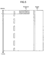
- the out-of-focus-amount calculating unit 104 calculates a difference between the image stored in the obtained-image storage unit 102 and the background image stored in the background-image storage unit 103. As a result, the difference is detected in an upper portion 301 of an image 300 as depicted in FIG. 5 , for example. When the difference as depicted in the portion 301 is detected, the out-of-focus-amount calculating unit 104 obtains a position "Y" of a lower end of the portion 301 on a Y-axis taking a positive value in a downward direction, with an upper left of the image 300 as an origin.
- the out-of-focus-amount calculating unit 104 also obtains a frequency distribution by performing a Fourier transform to the portion 301, and obtains strength of a higher frequency component than a predetermined frequency.
- the out-of-focus-amount calculating unit 104 calculates an out-of-focus amount as an out-of-focus level based on the obtained strength. When the strength has a smaller value, the out-of-focus amount of the portion 301 has a larger value. That is, the out-of-focus amount correlates inversely with the strength.
- the out-of-focus-amount calculating unit 104 registers the position and the out-of-focus amount into the out-of-focus-amount selection table 105 by relating the position and the amount to each other.
- the out-of-focus-amount calculating unit 104 calculates differences between all images stored in the obtained-image storage unit 102 and the background image. When the difference is detected, the out-of-focus-amount calculating unit 104 obtains a position and an out-of-focus amount, and stores the obtained position and the obtained out-of-focus amount into the out-of-focus-amount selection table 105. Because a vehicle moves from the upper part toward the lower part within the image 300, an out-of-focus amount "B1" related to a position of a value "Y1" near to the origin 0 is first registered into the out-of-focus-amount selection table 105, for example.
- An out-of-focus amount "B2" related to a position of a value "Y2" larger than the value "Y1” is then registered into the out-of-focus-amount selection table 105.
- An out-of-focus amount "B3" related to a position of a value "Y3" larger than the value "Y2” is further registered into the out-of-focus-amount selection table 105.
- the values obtained for the portion 301 can be any values so long as out-of-focus amounts as out-of-focus levels of the portion 301 can be calculated based on these values. For example, edges of the portion 301 can be obtained by a sobel filter, and a sum of edge strengths can be obtained as these values. Alternatively, contrast of the portion 301 can be used.
- the out-of-focus-amount selection table 105 is registered with the positions and the out-of-focus amounts obtained by the out-of-focus-amount calculating unit 104. Specifically, as depicted in FIG. 6 , a relationship between the positions and the out-of-focus amounts are registered into the out-of-focus-amount selection table 105.
- the focus adjusting unit 106 sets two ranges in advance. When an out-of-focus amount related to a position within one of the two ranges is registered into the out-of-focus-amount selection table 105, the focus adjusting unit 106 selects this out-of-focus amount. When an out-of-focus amount related to a position within the other of the two ranges is registered into the out-of-focus-amount selection table 105, the focus adjusting unit 106 selects this out-of-focus amount. The focus adjusting unit 106 determines whether the selected two out-of-focus amounts are smaller than a predetermined value. Specifically, as depicted in FIG.
- the focus adjusting unit 106 sets one range by a combination of two positions "Ya” and “Yb” located near the origin at the upper left of an image 310.
- the other range is set by a combination of two positions "Yc” and “Yd” located far from the origin. That is, when an out-of-focus amount "Bs" related to a position equal to or higher than Ya and equal to or lower than Yb is registered into the out-of-focus-amount selection table 105, the focus adjusting unit 106 selects the out-of-focus amount "Bs".
- the focus adjusting unit 106 selects the out-of-focus amount "Be". The focus adjusting unit 106 then determines whether both the out-of-focus amounts "Bs" and "Be" are smaller than a predetermined value.
- the predetermined value is set in advance in the focus adjusting unit 106. When the out-of-focus amount does not exceed the predetermined value, information concerning characters can be sufficiently obtained when the image recognition is performed to each of the portions.
- the focus adjusting unit 106 compares the out-of-focus amount "Bs" and the out-of-focus amount "Be", and adjusts the focus of the camera 200 based on a result of the comparison.
- the fact that the out-of-focus amount "Bs" is larger than the out-of-focus amount "Be” means that a portion detected as a vehicle in the upper part of the image has a larger out-of-focus level than that of a portion detected as a vehicle in the lower part of the image. That is, in FIG.
- the fact that the out-of-focus amount "Be" is larger than the out-of-focus amount "Bs” means that a portion detected as a vehicle in the lower part of the image has a larger out-of-focus level than that of a portion detected as a vehicle in the upper part of the image. That is, in FIG. 1 , this means that the camera 200 is focused on a position which is farther than the point 14 from the camera 200.
- the focus adjusting unit 106 outputs a control signal to the camera 200 to instruct the camera 200 to shift the focus in a direction away from the camera 200.
- the focus adjusting unit 106 outputs a control signal to the camera 200 to instruct the camera 200 to shift the focus in a direction toward the camera 200. Thereafter, the focus adjusting unit 106 similarly selects the other two out-of-focus amounts from the out-of-focus-amount selection table 105.
- the focus adjusting unit 106 compares the two out-of-focus amounts.
- the focus adjusting unit 106 adjusts the focus of the camera 200 based on a result of the comparison. With this arrangement, the focus of the camera 200 is adjusted onto near one point. Consequently, the camera 200 can be focused onto at least a vehicle passing through near this point.
- the focus adjusting unit 106 selects out-of-focus amounts of another vehicle passing through the imaging range of the camera 200 and performs a similar determination, because the out-of-focus amount "Bs" related to the position equal to or higher than Ya and equal to or lower than Yb and the out-of-focus amount "Be” related to the position equal to or higher than Yc and equal to or lower than Yd are registered again into the out-of-focus-amount selection table 105.
- the focus adjusting unit 106 compares the out-of-focus amounts "Bs" and "Be", and adjusts the focus of the camera 200. Therefore, the focus can be kept onto one point.
- FIG. 8 is a flowchart of the process performed by the focus adjusting apparatus 100. The process flow depicted in FIG. 8 is repeatedly performed during the operation of the focus adjusting apparatus 100.
- the image obtaining unit 101 first obtains an image picked up by the camera 200 (Step S101).
- the out-of-focus-amount calculating unit 104 calculates the out-of-focus-amount "Bs" based on high-frequency components higher than a predetermined frequency for a portion corresponding to a vehicle in the upper part of the image (Step S102).
- the out-of-focus-amount calculating unit 104 further calculates the out-of-focus-amount "Be" based on high-frequency components higher than the predetermined frequency for a portion corresponding to the vehicle in the lower part of the image (Step S103).
- the focus adjusting unit 106 When either one of the out-of-focus amounts “Bs" and “Be” is larger than the predetermined value, or when both the out-of-focus amounts “Bs” and “Be” are larger than the predetermined value (No at Step S104), and also when the out-of-focus amount “Bs” is larger than the out-of-focus amount "Be” (Yes at Step S105), the focus adjusting unit 106 outputs a control signal to the camera 200 to instruct the camera 200 to shift the focus in a direction away from the camera 200 (Step S106), and finishes the process.
- the focus adjusting unit 106 outputs a control signal to the camera 200 to instruct the camera 200 to shift the focus in a direction toward the camera 200 (Step S107), and finishes the process.
- the focus adjusting apparatus 100 adjusts the focus of the camera 200 based on the out-of-focus amounts of portions corresponding to a vehicle within two images, each time when the vehicle passes through the imaging range of the camera 200.
- the focus adjusting apparatus 100 can focus the camera 200 onto near one point within the imaging range. That is, the focus adjusting apparatus 100 can focus the camera 200 onto at least a vehicle passing through near the point 14.
- the configuration of the focus adjusting apparatus 100 according to the present embodiment depicted in FIG. 2 can be variously modified without departing from the spirit or scope of the present invention.
- functions of the image obtaining unit 101, the out-of-focus-amount calculating unit 104, and the focus adjusting unit 106 included in the focus adjusting apparatus 100 can be implemented as software.
- a central processing unit (CPU) can perform this software, thereby performing functions equivalent to the functions of the focus adjusting apparatus 100.
- CPU central processing unit
- One example of a computer that executes a focus adjusting program 431 having the functions of the image obtaining unit 101, the out-of-focus-amount calculating unit 104, and the focus adjusting unit 106 implemented as software is shown below.
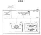
- FIG. 9 is a functional block diagram of a computer 400 that executes the focus adjusting program 431.
- the computer 400 includes a CPU 410 that performs various operation processes, a random access memory (RAM) 420 that temporarily stores therein various kinds of information, a hard disk drive 430, a camera 440 that picks up an image of a vehicle, and a network interface device 450 that exchanges data with other computers via a network, which are connected to each other via a bus 460.
- RAM random access memory
- the hard disk drive 430 stores therein the focus adjusting program 431 having functions similar to those of the image obtaining unit 101, the out-of-focus-amount calculating unit 104, and the focus adjusting unit 106 depicted in FIG. 4 .
- the hard disk drive 430 also includes a background image 432 corresponding to the background image stored in the background-image storage unit 103 as depicted in FIG. 4 .
- the focus adjusting program 431 When the CPU 410 reads the focus adjusting program 431 from the hard disk drive 430 and develops the read program into the RAM 420, the focus adjusting program 431 functions as a focus adjusting process 421.
- the focus adjusting process 421 properly develops information and the like read from the background image 432, into a region allocated to the focus adjusting process 421 on the RAM 420, and performs various kinds of data processes based on the developed data and the like.
- the focus adjusting program 431 is not necessarily required to be stored into the hard disk drive 430.
- the computer 400 can read the program stored in a storage medium such as a memory card, and can execute this program.
- This program can be also stored into another computer (or a server) connected to the computer 400 via a public line, the Internet, a local area network (LAN), a wide area network (WAN), or the like.
- the computer 400 can read this program from the another computer or the server and execute the program.
- the camera can be focused onto a moving object.
Landscapes
- Engineering & Computer Science (AREA)
- Physics & Mathematics (AREA)
- General Physics & Mathematics (AREA)
- Multimedia (AREA)
- Theoretical Computer Science (AREA)
- Signal Processing (AREA)
- Computer Vision & Pattern Recognition (AREA)
- Optics & Photonics (AREA)
- Studio Devices (AREA)
- Automatic Focus Adjustment (AREA)
- Focusing (AREA)
Abstract
Description
- The embodiments are discussed herein are directed to a focus adjusting apparatus and a focus adjusting method for adjusting the focus of a camera imaging a moving object.
- Conventionally, in some cases, a moving object moving on a plane such as a road is imaged at a predetermined depression angle, by a camera set above the plane. An image processing device is sometimes used to recognize a specific pattern of the moving object within an image picked up by the camera, thereby obtaining information of the pattern. In this image recognition, it is important that the moving object on the image is clear to make it possible to sufficiently obtain information of the pattern.
- A technique can be used to enable to automatically focus a camera onto a moving object. For example, a technique is known that enables to image a moving object at plural times each time the moving object passes within an imaging range, and estimate a motion of the moving object based on a change of an out-of-focus level of the moving object within each image, thereby adjusting the focus onto the moving object (see Japanese Laid-open Patent Publication No.
07-92381 - However, in the conventional technique described above, a lens is focused onto the moving object each time. Therefore, the focus is sometimes deviated far from the moving object because of a wrong estimation. In such cases, the camera cannot be focused onto the moving object.
- The present invention is made to solve the above described problems, and an object of the invention is to provide a focus adjusting apparatus and method that can focus the camera on a moving object.
- According to an aspect of the invention, a focus adjusting apparatus adjusts a focus of a camera imaging a moving object. The apparatus includes a calculating unit that calculates a first out-of-focus level of a portion corresponding to the moving object within a first region of an image picked up by the camera, and calculates a second out-of-focus level of a portion corresponding to the moving object within a second region of an image picked up by the camera; and a focus adjusting unit that shifts the focus of the camera in a direction in which the camera is focused onto the portion corresponding to the moving object within the first region when the first out-of-focus level calculated by the calculating unit is larger than the second out-of-focus level calculated by the calculating unit, and that shifts the focus of the camera in a direction in which the camera is focused onto the portion corresponding to the moving object within the second region when the second out-of-focus level is larger than the first out-of-focus level.
- The object and advantages of the invention will be realized and attained by means of the elements and combinations particularly pointed out in the claims.
- It is to be understood that both the foregoing general description and the following detailed description are exemplary and explanatory and are not restrictive of the invention, as claimed.
-
-
FIG. 1 is a schematic diagram for explaining an outline of a focus adjusting apparatus according to an embodiment of the present invention; -
FIG. 2 depicts images picked up by a camera; -
FIG. 3 depicts images picked up by a camera; -
FIG. 4 is a block diagram of a configuration of the focus adjusting apparatus; -
FIG. 5 is a schematic diagram for explaining determination of a position of a Y-axis performed by an out-of-focus-amount calculating unit; -
FIG. 6 is a specific example of an out-of-focus-amount selection table; -
FIG. 7 is a schematic diagram for explaining an out-of-focus-amount selecting process performed by a focus adjusting unit; -
FIG. 8 is a flowchart of a process performed by the focus adjusting apparatus; and -
FIG. 9 depicts a computer that executes a focus adjusting program. - Preferred embodiments of a focus adjusting apparatus and a focus adjusting method according to the present embodiment will be explained in detail below with reference to the accompanying drawings.
- An outline of a focus adjusting apparatus according to one embodiment of the present invention is explained first with reference to
FIGS. 1 to 3 .FIG. 1 is a schematic diagram for explaining the outline of the focus adjusting apparatus according to the present embodiment. As depicted inFIG. 1 , this embodiment assumes a case in which acamera 200 fixed above aroad 10 images at apredetermined depression angle 11, avehicle 12 running on theroad 10 in a direction of an arrow.FIGS. 2 and3 depict images picked up by thecamera 200. - There is a technique that enables to use an image processing device (not depicted) that recognizes a portion corresponding to a
license plate 13 of thevehicle 12 within an image picked up by thecamera 200, and obtains information concerning characters described in thelicense plate 13 of thevehicle 12. To obtain information concerning the characters by the image recognition, it is important that thecamera 200 clearly images thevehicle 12. For this purpose, it is preferable to focus thecamera 200 onto one point and cause thecamera 200 to pick up images in focus of at least the vehicle passing through near this point. - A
focus adjusting apparatus 100 can adjust the focus of thecamera 200 to enable to image a vehicle within a range of a certain distance from the camera 200 (for example, a vehicle seen between A and B within animage 20 inFIG. 2 ) in sharpness necessary to recognize the image even when the focus of thecamera 200 roughly set at the beginning. Specifically, thefocus adjusting apparatus 100 obtains theimage 20 and animage 22 picked up by thecamera 200 as depicted inFIGS. 2 and3 . Aportion 21 in an upper part of theimage 20 corresponds to thevehicle 12. Aportion 23 in a lower part of theimage 22 corresponds to thevehicle 12. Thefocus adjusting apparatus 100 calculates an out-of-focus level of theportion 21 within theimage 20 and an out-of-focus level of theportion 23 within theimage 22 based on contrast and a high-frequency component of each of the portions. When the out-of-focus level of theportion 21 is larger than the out-of-focus level of theportion 23, thefocus adjusting apparatus 100 shifts the focus of thecamera 200 in a direction away from thecamera 200 so that the focus is adjusted onto theportion 21. On the other hand, when the out-of-focus level of theportion 23 is larger than the out-of-focus level of theportion 21, thefocus adjusting apparatus 100 shifts the focus of thecamera 200 in a direction toward thecamera 200 so that the focus is adjusted onto theportion 23. - The
focus adjusting apparatus 100 also obtains images of other vehicles passing through an imaging range of thecamera 200 so that the images include portions corresponding to these vehicles in an upper part of the image and in a lower part of the image like theimages camera 200 in the above-described process. As a result, the focus of thecamera 200 is adjusted so that the out-of-focus levels of the vehicles from the upper part of the image to the lower part of the image become equal to or lower than a predetermined value. That is, thefocus adjusting apparatus 100 according to the present embodiment can focus thecamera 200 on the vehicles. - Even when the
vehicle 12 running on theroad 10 in an opposite direction to that indicated by the arrow inFIG. 1 is imaged by thecamera 200 in a different assumption from that of the present embodiment, thefocus adjusting apparatus 100 can also adjust the focus of thecamera 200 in a similar manner. - A configuration of the
focus adjusting apparatus 100 is explained next.FIG. 4 is a block diagram of the configuration of thefocus adjusting apparatus 100 according to the present embodiment. As depicted inFIG. 4 , thefocus adjusting apparatus 100 includes animage obtaining unit 101, an obtained-image storage unit 102, a background-image storage unit 103, an out-of-focus-amount calculating unit 104, an out-of-focus-amount selection table 105, and afocus adjusting unit 106. - The
image obtaining unit 101 obtains images picked up by thecamera 200 at predetermined time intervals, and stores the obtained images into the obtained-image storage unit 102. The obtained-image storage unit 102 stores therein the images obtained by theimage obtaining unit 101. The background-image storage unit 103 stores therein a background image previously picked up by thecamera 200 while no vehicle is running through the imaging range of thecamera 200. - The out-of-focus-
amount calculating unit 104 calculates a difference between the image stored in the obtained-image storage unit 102 and the background image stored in the background-image storage unit 103. As a result, the difference is detected in anupper portion 301 of animage 300 as depicted inFIG. 5 , for example. When the difference as depicted in theportion 301 is detected, the out-of-focus-amount calculating unit 104 obtains a position "Y" of a lower end of theportion 301 on a Y-axis taking a positive value in a downward direction, with an upper left of theimage 300 as an origin. The out-of-focus-amount calculating unit 104 also obtains a frequency distribution by performing a Fourier transform to theportion 301, and obtains strength of a higher frequency component than a predetermined frequency. The out-of-focus-amount calculating unit 104 calculates an out-of-focus amount as an out-of-focus level based on the obtained strength. When the strength has a smaller value, the out-of-focus amount of theportion 301 has a larger value. That is, the out-of-focus amount correlates inversely with the strength. The out-of-focus-amount calculating unit 104 registers the position and the out-of-focus amount into the out-of-focus-amount selection table 105 by relating the position and the amount to each other. The out-of-focus-amount calculating unit 104 calculates differences between all images stored in the obtained-image storage unit 102 and the background image. When the difference is detected, the out-of-focus-amount calculating unit 104 obtains a position and an out-of-focus amount, and stores the obtained position and the obtained out-of-focus amount into the out-of-focus-amount selection table 105. Because a vehicle moves from the upper part toward the lower part within theimage 300, an out-of-focus amount "B1" related to a position of a value "Y1" near to the origin 0 is first registered into the out-of-focus-amount selection table 105, for example. An out-of-focus amount "B2" related to a position of a value "Y2" larger than the value "Y1" is then registered into the out-of-focus-amount selection table 105. An out-of-focus amount "B3" related to a position of a value "Y3" larger than the value "Y2" is further registered into the out-of-focus-amount selection table 105. The values obtained for theportion 301 can be any values so long as out-of-focus amounts as out-of-focus levels of theportion 301 can be calculated based on these values. For example, edges of theportion 301 can be obtained by a sobel filter, and a sum of edge strengths can be obtained as these values. Alternatively, contrast of theportion 301 can be used. - The out-of-focus-amount selection table 105 is registered with the positions and the out-of-focus amounts obtained by the out-of-focus-
amount calculating unit 104. Specifically, as depicted inFIG. 6 , a relationship between the positions and the out-of-focus amounts are registered into the out-of-focus-amount selection table 105. - The
focus adjusting unit 106 sets two ranges in advance. When an out-of-focus amount related to a position within one of the two ranges is registered into the out-of-focus-amount selection table 105, thefocus adjusting unit 106 selects this out-of-focus amount. When an out-of-focus amount related to a position within the other of the two ranges is registered into the out-of-focus-amount selection table 105, thefocus adjusting unit 106 selects this out-of-focus amount. Thefocus adjusting unit 106 determines whether the selected two out-of-focus amounts are smaller than a predetermined value. Specifically, as depicted inFIG. 7 , thefocus adjusting unit 106 sets one range by a combination of two positions "Ya" and "Yb" located near the origin at the upper left of animage 310. The other range is set by a combination of two positions "Yc" and "Yd" located far from the origin. That is, when an out-of-focus amount "Bs" related to a position equal to or higher than Ya and equal to or lower than Yb is registered into the out-of-focus-amount selection table 105, thefocus adjusting unit 106 selects the out-of-focus amount "Bs". When an out-of-focus amount "Be" related to a position equal to or higher than Yc and equal to or lower than Yd is then registered into the out-of-focus-amount selection table 105, thefocus adjusting unit 106 selects the out-of-focus amount "Be". Thefocus adjusting unit 106 then determines whether both the out-of-focus amounts "Bs" and "Be" are smaller than a predetermined value. The predetermined value is set in advance in thefocus adjusting unit 106. When the out-of-focus amount does not exceed the predetermined value, information concerning characters can be sufficiently obtained when the image recognition is performed to each of the portions. - As a result of the determination, when either one of the out-of-focus amounts "Bs" and "Be" is larger than the predetermined value, or when both the out-of-focus amounts "Bs" and "Be" are larger than the predetermined value, the
focus adjusting unit 106 compares the out-of-focus amount "Bs" and the out-of-focus amount "Be", and adjusts the focus of thecamera 200 based on a result of the comparison. The fact that the out-of-focus amount "Bs" is larger than the out-of-focus amount "Be" means that a portion detected as a vehicle in the upper part of the image has a larger out-of-focus level than that of a portion detected as a vehicle in the lower part of the image. That is, inFIG. 1 , this means that thecamera 200 is focused on a position which is nearer thecamera 200 than apoint 14. On the other hand, the fact that the out-of-focus amount "Be" is larger than the out-of-focus amount "Bs" means that a portion detected as a vehicle in the lower part of the image has a larger out-of-focus level than that of a portion detected as a vehicle in the upper part of the image. That is, inFIG. 1 , this means that thecamera 200 is focused on a position which is farther than thepoint 14 from thecamera 200. Therefore, when the out-of-focus amount "Bs" is larger than the out-of-focus amount "Be", thefocus adjusting unit 106 outputs a control signal to thecamera 200 to instruct thecamera 200 to shift the focus in a direction away from thecamera 200. On the other hand, when the out-of-focus amount "Be" is larger than the out-of-focus amount "Bs", thefocus adjusting unit 106 outputs a control signal to thecamera 200 to instruct thecamera 200 to shift the focus in a direction toward thecamera 200. Thereafter, thefocus adjusting unit 106 similarly selects the other two out-of-focus amounts from the out-of-focus-amount selection table 105. When either one of the selected two out-of-focus amounts is larger than the predetermined value, or when both the two out-of-focus amounts are larger than the predetermined value, thefocus adjusting unit 106 compares the two out-of-focus amounts. Thefocus adjusting unit 106 adjusts the focus of thecamera 200 based on a result of the comparison. With this arrangement, the focus of thecamera 200 is adjusted onto near one point. Consequently, thecamera 200 can be focused onto at least a vehicle passing through near this point. - On the other hand, as a result of the determination, when both the out-of-focus amounts "Bs" and "Be" are smaller than the predetermined value, the
focus adjusting unit 106 selects out-of-focus amounts of another vehicle passing through the imaging range of thecamera 200 and performs a similar determination, because the out-of-focus amount "Bs" related to the position equal to or higher than Ya and equal to or lower than Yb and the out-of-focus amount "Be" related to the position equal to or higher than Yc and equal to or lower than Yd are registered again into the out-of-focus-amount selection table 105. As explained above, only when none of the out-of-focus amounts "Bs" and "Be" is smaller than the predetermined value, thefocus adjusting unit 106 compares the out-of-focus amounts "Bs" and "Be", and adjusts the focus of thecamera 200. Therefore, the focus can be kept onto one point. - A flow of a process performed by the
focus adjusting apparatus 100 is explained next.FIG. 8 is a flowchart of the process performed by thefocus adjusting apparatus 100. The process flow depicted inFIG. 8 is repeatedly performed during the operation of thefocus adjusting apparatus 100. - As depicted in
FIG. 8 , in thefocus adjusting apparatus 100, theimage obtaining unit 101 first obtains an image picked up by the camera 200 (Step S101). The out-of-focus-amount calculating unit 104 calculates the out-of-focus-amount "Bs" based on high-frequency components higher than a predetermined frequency for a portion corresponding to a vehicle in the upper part of the image (Step S102). The out-of-focus-amount calculating unit 104 further calculates the out-of-focus-amount "Be" based on high-frequency components higher than the predetermined frequency for a portion corresponding to the vehicle in the lower part of the image (Step S103). - When either one of the out-of-focus amounts "Bs" and "Be" is larger than the predetermined value, or when both the out-of-focus amounts "Bs" and "Be" are larger than the predetermined value (No at Step S104), and also when the out-of-focus amount "Bs" is larger than the out-of-focus amount "Be" (Yes at Step S105), the
focus adjusting unit 106 outputs a control signal to thecamera 200 to instruct thecamera 200 to shift the focus in a direction away from the camera 200 (Step S106), and finishes the process. - On the other hand, when either one of the out-of-focus amounts "Bs" and "Be" is larger than the predetermined value, or when both the out-of-focus amounts "Bs" and "Be" are larger than the predetermined value (No at Step S104), and also when the out-of-focus amount "Be" is larger than the out-of-focus amount "Bs" (No at Step S105), the
focus adjusting unit 106 outputs a control signal to thecamera 200 to instruct thecamera 200 to shift the focus in a direction toward the camera 200 (Step S107), and finishes the process. - As described above, the
focus adjusting apparatus 100 according to the present embodiment adjusts the focus of thecamera 200 based on the out-of-focus amounts of portions corresponding to a vehicle within two images, each time when the vehicle passes through the imaging range of thecamera 200. By repeatedly adjusting the focus, thefocus adjusting apparatus 100 can focus thecamera 200 onto near one point within the imaging range. That is, thefocus adjusting apparatus 100 can focus thecamera 200 onto at least a vehicle passing through near thepoint 14. - The configuration of the
focus adjusting apparatus 100 according to the present embodiment depicted inFIG. 2 can be variously modified without departing from the spirit or scope of the present invention. For example, functions of theimage obtaining unit 101, the out-of-focus-amount calculating unit 104, and thefocus adjusting unit 106 included in thefocus adjusting apparatus 100 can be implemented as software. A central processing unit (CPU) can perform this software, thereby performing functions equivalent to the functions of thefocus adjusting apparatus 100. One example of a computer that executes afocus adjusting program 431 having the functions of theimage obtaining unit 101, the out-of-focus-amount calculating unit 104, and thefocus adjusting unit 106 implemented as software is shown below. -
FIG. 9 is a functional block diagram of acomputer 400 that executes thefocus adjusting program 431. Thecomputer 400 includes aCPU 410 that performs various operation processes, a random access memory (RAM) 420 that temporarily stores therein various kinds of information, ahard disk drive 430, acamera 440 that picks up an image of a vehicle, and anetwork interface device 450 that exchanges data with other computers via a network, which are connected to each other via a bus 460. - The
hard disk drive 430 stores therein thefocus adjusting program 431 having functions similar to those of theimage obtaining unit 101, the out-of-focus-amount calculating unit 104, and thefocus adjusting unit 106 depicted inFIG. 4 . Thehard disk drive 430 also includes abackground image 432 corresponding to the background image stored in the background-image storage unit 103 as depicted inFIG. 4 . - When the
CPU 410 reads thefocus adjusting program 431 from thehard disk drive 430 and develops the read program into theRAM 420, thefocus adjusting program 431 functions as afocus adjusting process 421. Thefocus adjusting process 421 properly develops information and the like read from thebackground image 432, into a region allocated to thefocus adjusting process 421 on theRAM 420, and performs various kinds of data processes based on the developed data and the like. - The
focus adjusting program 431 is not necessarily required to be stored into thehard disk drive 430. Thecomputer 400 can read the program stored in a storage medium such as a memory card, and can execute this program. This program can be also stored into another computer (or a server) connected to thecomputer 400 via a public line, the Internet, a local area network (LAN), a wide area network (WAN), or the like. Thecomputer 400 can read this program from the another computer or the server and execute the program. - According to the embodiments, the camera can be focused onto a moving object.
- All examples and conditional language recited herein are intended for pedagogical purposes to aid the reader in understanding the invention and the concepts contributed by the inventor to furthering the art, and are to be construed as being without limitation to such specifically recited examples and conditions, nor does the organization of such examples in the specification relate to a showing of the superiority and inferiority of the invention. Although the embodiment(s) of the present inventions have been described in detail, it should be understood that the various changes, substitutions, and alterations could be made hereto without departing from the spirit and scope of the invention.
Claims (7)
- A focus adjusting apparatus (100) that adjusts a focus of a camera (200) imaging a moving object (12), the focus adjusting apparatus (100) comprising:a calculating unit (104) that calculates a first out-of-focus level of a portion (21) corresponding to the moving object (12) within a first region of an image (20) picked up by the camera (200), and calculates a second out-of-focus level of a portion (23) corresponding to the moving object (12) within a second region of an image (22) picked up by the camera (200); anda focus adjusting unit (106) that shifts the focus of the camera (200) in a direction in which the camera (200) is focused onto the portion (21) corresponding to the moving object (12) within the first region when the first out-of-focus level calculated by the calculating unit (104) is larger than the second out-of-focus level calculated by the calculating unit (104), and that shifts the focus of the camera (200) in a direction in which the camera (200) is focused onto the portion (23) corresponding to the moving object (12) within the second region when the second out-of-focus level is larger than the first out-of-focus level.
- The focus adjusting apparatus (100) according to claim 1, wherein when both the first out-of-focus level calculated by the calculating unit (104) and the second out-of-focus level calculated by the calculating unit (104) are smaller than a certain reference, the focus adjusting unit (106) adjusts the focus of the camera (200) onto the same position as the current position.
- The focus adjusting apparatus (100) according to claim 1 or 2, wherein the calculating unit (104) calculates the first out-of-focus level and the second out-of-focus level based on a high-frequency component of each of the portions (21, 23) corresponding to the moving object (12).
- The focus adjusting apparatus (100) according to claim 1 or 2, wherein the calculating unit (104) calculates the first out-of-focus level and the second out-of-focus level based on contrast of each of the portions (21, 23) corresponding to the moving object (12).
- The focus adjusting apparatus (100) according to claim 1 or 2, wherein the calculating unit (104) calculates the first out-of-focus level and the second out-of-focus level based on edge strength of each of the portions (21, 23) corresponding to the moving object (12).
- A focus adjusting method of adjusting a focus of a camera (200) imaging a moving object (12), the focus adjusting method comprising:calculating a first out-of-focus level of a portion (21) corresponding to the moving object (12) within a first region of an image (20) picked up by the camera (200);calculating a second out-of-focus level of a portion (23) corresponding to the moving object (12) within a second region of an image (22) picked up by the camera (200); andshifting the focus of the camera (200) in a direction in which the camera (200) is focused onto the portion (21) corresponding to the moving object (12) within the first region when the first out-of-focus level calculated in the calculating of the first out-of-focus level is larger than the second out-of-focus level calculated in the calculating of the second out-of-level, and shifting the focus of the camera (200) in a direction in which the camera (200) is focused onto the portion (23) corresponding to the moving object (12) within the second region when the second out-of-focus level is larger than the first out-of-focus level.
- A focus adjusting program for causing a computer to perform a method of adjusting a focus of a camera (200) imaging a moving object (12), wherein the focus adjusting program causes the computer to perform:calculating a first out-of-focus level of a portion (21) corresponding to the moving object (12) within a first region of an image (20) picked up by the camera (200);calculating a second out-of-focus level of a portion (23) corresponding to the moving object (12) within a second region of an image (22) picked up by the camera (200); andshifting the focus of the camera (200) in a direction in which the camera (200) is focused onto the portion (21) corresponding to the moving object (12) within the first region when the first out-of-focus level calculated in the calculating of the first out-of-focus level is larger than the second out-of-focus level calculated in the calculating of the second out-of-level, and shifting the focus of the camera (200) in a direction in which the camera (200) is focused onto the portion (23) corresponding to the moving object (12) within the second region when the second out-of-focus level is larger than the first out-of-focus level.
Applications Claiming Priority (1)
| Application Number | Priority Date | Filing Date | Title |
|---|---|---|---|
| JP2008227516A JP5211949B2 (en) | 2008-09-04 | 2008-09-04 | Focus adjustment apparatus, focus adjustment method, and focus adjustment program |
Publications (2)
| Publication Number | Publication Date |
|---|---|
| EP2161604A1 true EP2161604A1 (en) | 2010-03-10 |
| EP2161604B1 EP2161604B1 (en) | 2018-06-06 |
Family
ID=41395869
Family Applications (1)
| Application Number | Title | Priority Date | Filing Date |
|---|---|---|---|
| EP09008383.3A Not-in-force EP2161604B1 (en) | 2008-09-04 | 2009-06-26 | Focus adjusting apparatus and method |
Country Status (5)
| Country | Link |
|---|---|
| US (1) | US7873268B2 (en) |
| EP (1) | EP2161604B1 (en) |
| JP (1) | JP5211949B2 (en) |
| KR (1) | KR101054108B1 (en) |
| CN (1) | CN101666956B (en) |
Cited By (1)
| Publication number | Priority date | Publication date | Assignee | Title |
|---|---|---|---|---|
| CN109817001A (en) * | 2017-11-21 | 2019-05-28 | 德尔福技术公司 | Virtual barrier system |
Families Citing this family (11)
| Publication number | Priority date | Publication date | Assignee | Title |
|---|---|---|---|---|
| ES2661168T3 (en) | 2003-07-12 | 2018-03-27 | Accelerate Diagnostics, Inc. | Sensitive and rapid biodetection |
| US20120077206A1 (en) | 2003-07-12 | 2012-03-29 | Accelr8 Technology Corporation | Rapid Microbial Detection and Antimicrobial Susceptibility Testing |
| US10254204B2 (en) | 2011-03-07 | 2019-04-09 | Accelerate Diagnostics, Inc. | Membrane-assisted purification |
| US9434937B2 (en) | 2011-03-07 | 2016-09-06 | Accelerate Diagnostics, Inc. | Rapid cell purification systems |
| US9677109B2 (en) | 2013-03-15 | 2017-06-13 | Accelerate Diagnostics, Inc. | Rapid determination of microbial growth and antimicrobial susceptibility |
| JP6201798B2 (en) * | 2014-02-12 | 2017-09-27 | 富士通株式会社 | System, information processing apparatus, information processing method, and information processing program |
| US10023895B2 (en) | 2015-03-30 | 2018-07-17 | Accelerate Diagnostics, Inc. | Instrument and system for rapid microogranism identification and antimicrobial agent susceptibility testing |
| US10253355B2 (en) | 2015-03-30 | 2019-04-09 | Accelerate Diagnostics, Inc. | Instrument and system for rapid microorganism identification and antimicrobial agent susceptibility testing |
| CN107091800A (en) * | 2017-06-06 | 2017-08-25 | 深圳小孚医疗科技有限公司 | Focusing system and focus method for micro-imaging particle analysis |
| DE102020124785A1 (en) | 2020-09-23 | 2022-03-24 | Connaught Electronics Ltd. | Method for monitoring a focus of a camera arranged on a motor vehicle, computer program product, computer-readable storage medium and system |
| DE102020211879A1 (en) * | 2020-09-23 | 2022-03-24 | Robert Bosch Gesellschaft mit beschränkter Haftung | Method for determining an operating parameter for operating an environment detection system for a vehicle and environment detection system |
Citations (4)
| Publication number | Priority date | Publication date | Assignee | Title |
|---|---|---|---|---|
| JPH04169987A (en) * | 1990-11-01 | 1992-06-17 | Omron Corp | Method for detecting character string in image information |
| JPH0792381A (en) | 1994-07-11 | 1995-04-07 | Nikon Corp | Automatic focus adjustment device |
| JP2000322686A (en) * | 1999-05-13 | 2000-11-24 | Toshiba Corp | Vehicle number plate recognition device |
| EP2037321A1 (en) * | 2007-09-11 | 2009-03-18 | Sony Corporation | Imaging device and in-focus control method |
Family Cites Families (20)
| Publication number | Priority date | Publication date | Assignee | Title |
|---|---|---|---|---|
| JP2513191B2 (en) * | 1986-10-06 | 1996-07-03 | ミノルタ株式会社 | Automatic focus detection device in image reading device |
| JPS63169879A (en) * | 1987-01-08 | 1988-07-13 | Nec Corp | Automatic focus system |
| US5187515A (en) * | 1988-05-13 | 1993-02-16 | Minolta Camera Kabushiki Kaisha | Camera having automatic focus adjusting apparatus |
| US5179407A (en) * | 1989-06-19 | 1993-01-12 | Nikon Corporation | Automatic focusing device |
| JPH03117182A (en) * | 1989-09-29 | 1991-05-17 | Sony Corp | Video camera |
| JP3010681B2 (en) * | 1990-05-22 | 2000-02-21 | 株式会社ニコン | Automatic focusing device |
| JPH0479579A (en) * | 1990-07-20 | 1992-03-12 | Toshiba Corp | Auto-focusing circuit |
| JP3465330B2 (en) * | 1993-12-22 | 2003-11-10 | 株式会社ニコン | Multi-area focusing camera |
| JPH08124083A (en) * | 1994-10-21 | 1996-05-17 | Toyota Motor Corp | Mobile imaging device |
| JP3379324B2 (en) * | 1996-02-08 | 2003-02-24 | トヨタ自動車株式会社 | Moving object detection method and apparatus |
| JP3435623B2 (en) * | 1996-05-15 | 2003-08-11 | 株式会社日立製作所 | Traffic flow monitoring device |
| JP3732665B2 (en) * | 1998-12-22 | 2006-01-05 | 株式会社リコー | Automatic focus control device and focusing operation determination method thereof |
| JP2001004909A (en) * | 1999-06-18 | 2001-01-12 | Olympus Optical Co Ltd | Camera having automatic focusing device |
| JP4334784B2 (en) * | 2001-06-11 | 2009-09-30 | 日本放送協会 | Autofocus device and imaging device using the same |
| JP2005308960A (en) * | 2004-04-20 | 2005-11-04 | Canon Inc | Imaging device with automatic focusing device |
| JP2006267220A (en) * | 2005-03-22 | 2006-10-05 | Fujinon Corp | Auto focus system |
| US7561790B2 (en) * | 2004-12-28 | 2009-07-14 | Fujinon Corporation | Auto focus system |
| KR100706953B1 (en) * | 2005-07-11 | 2007-04-12 | 삼성전기주식회사 | Camera auto focusing device and method |
| JP2007104248A (en) | 2005-10-04 | 2007-04-19 | Nikon Corp | Electronic camera and program |
| JP2007139892A (en) | 2005-11-15 | 2007-06-07 | Olympus Corp | Focusing detection device |
-
2008
- 2008-09-04 JP JP2008227516A patent/JP5211949B2/en not_active Expired - Fee Related
-
2009
- 2009-06-26 EP EP09008383.3A patent/EP2161604B1/en not_active Not-in-force
- 2009-06-29 US US12/458,025 patent/US7873268B2/en not_active Expired - Fee Related
- 2009-07-15 KR KR1020090064383A patent/KR101054108B1/en not_active Expired - Fee Related
- 2009-07-29 CN CN2009101596745A patent/CN101666956B/en not_active Expired - Fee Related
Patent Citations (4)
| Publication number | Priority date | Publication date | Assignee | Title |
|---|---|---|---|---|
| JPH04169987A (en) * | 1990-11-01 | 1992-06-17 | Omron Corp | Method for detecting character string in image information |
| JPH0792381A (en) | 1994-07-11 | 1995-04-07 | Nikon Corp | Automatic focus adjustment device |
| JP2000322686A (en) * | 1999-05-13 | 2000-11-24 | Toshiba Corp | Vehicle number plate recognition device |
| EP2037321A1 (en) * | 2007-09-11 | 2009-03-18 | Sony Corporation | Imaging device and in-focus control method |
Cited By (1)
| Publication number | Priority date | Publication date | Assignee | Title |
|---|---|---|---|---|
| CN109817001A (en) * | 2017-11-21 | 2019-05-28 | 德尔福技术公司 | Virtual barrier system |
Also Published As
| Publication number | Publication date |
|---|---|
| US7873268B2 (en) | 2011-01-18 |
| CN101666956A (en) | 2010-03-10 |
| JP2010060939A (en) | 2010-03-18 |
| US20100054723A1 (en) | 2010-03-04 |
| KR20100028469A (en) | 2010-03-12 |
| JP5211949B2 (en) | 2013-06-12 |
| EP2161604B1 (en) | 2018-06-06 |
| KR101054108B1 (en) | 2011-08-03 |
| CN101666956B (en) | 2011-06-15 |
Similar Documents
| Publication | Publication Date | Title |
|---|---|---|
| EP2161604A1 (en) | Focus adjusting apparatus and method | |
| EP2704419B1 (en) | System and method for utilizing enhanced scene detection in a depth estimation procedure | |
| US20090231639A1 (en) | Image processor, image processing method, and computer program product | |
| US11153552B2 (en) | Image processing apparatus, image processing method and non-transitory computer-readable storage medium | |
| KR102226845B1 (en) | System and method for object recognition using local binarization | |
| JP2009093638A (en) | Image detection apparatus and image detection method | |
| US9361674B2 (en) | Image processing apparatus, image processing method, and storage medium | |
| KR102226843B1 (en) | System and method for object detection | |
| US10373329B2 (en) | Information processing apparatus, information processing method and storage medium for determining an image to be subjected to a character recognition processing | |
| JP6423314B2 (en) | Corresponding point search method and distance measuring device | |
| JP2015207090A (en) | Image processing apparatus and control method thereof | |
| JP4943228B2 (en) | Image matching processing method | |
| JP2013026936A (en) | Image processing apparatus, image processing method, and program | |
| US9350892B2 (en) | Image processing apparatus and image processing method | |
| KR102239564B1 (en) | System and method for object recognition different by administrative area | |
| JP2005182164A (en) | Image area determination method, and image area determination apparatus, image correction apparatus, and digital watermark extraction apparatus capable of using method | |
| US11948328B2 (en) | Image-processing device, image-processing method, and image-processing program | |
| US9131182B2 (en) | Image processing apparatus, method and storage medium | |
| US12518368B2 (en) | Image processing apparatus, image processing method, and storage medium | |
| JP4315349B2 (en) | Image processing method, apparatus, and program | |
| JP2022110415A (en) | Image processing device, image processing method, and program | |
| JP5146653B2 (en) | Image processing apparatus and image processing program | |
| JP2007206963A (en) | Image processing apparatus, image processing method, program, and storage medium | |
| JP4207863B2 (en) | Mobile tracking device | |
| JP2019177764A (en) | Parking space detection device, parking space detection method and control program |
Legal Events
| Date | Code | Title | Description |
|---|---|---|---|
| PUAI | Public reference made under article 153(3) epc to a published international application that has entered the european phase |
Free format text: ORIGINAL CODE: 0009012 |
|
| AK | Designated contracting states |
Kind code of ref document: A1 Designated state(s): AT BE BG CH CY CZ DE DK EE ES FI FR GB GR HR HU IE IS IT LI LT LU LV MC MK MT NL NO PL PT RO SE SI SK TR |
|
| AX | Request for extension of the european patent |
Extension state: AL BA RS |
|
| 17P | Request for examination filed |
Effective date: 20100910 |
|
| 17Q | First examination report despatched |
Effective date: 20170707 |
|
| GRAP | Despatch of communication of intention to grant a patent |
Free format text: ORIGINAL CODE: EPIDOSNIGR1 |
|
| INTG | Intention to grant announced |
Effective date: 20180226 |
|
| GRAS | Grant fee paid |
Free format text: ORIGINAL CODE: EPIDOSNIGR3 |
|
| GRAA | (expected) grant |
Free format text: ORIGINAL CODE: 0009210 |
|
| AK | Designated contracting states |
Kind code of ref document: B1 Designated state(s): AT BE BG CH CY CZ DE DK EE ES FI FR GB GR HR HU IE IS IT LI LT LU LV MC MK MT NL NO PL PT RO SE SI SK TR |
|
| REG | Reference to a national code |
Ref country code: GB Ref legal event code: FG4D |
|
| REG | Reference to a national code |
Ref country code: CH Ref legal event code: EP Ref country code: AT Ref legal event code: REF Ref document number: 1006732 Country of ref document: AT Kind code of ref document: T Effective date: 20180615 |
|
| REG | Reference to a national code |
Ref country code: IE Ref legal event code: FG4D |
|
| REG | Reference to a national code |
Ref country code: FR Ref legal event code: PLFP Year of fee payment: 10 |
|
| REG | Reference to a national code |
Ref country code: DE Ref legal event code: R096 Ref document number: 602009052636 Country of ref document: DE |
|
| REG | Reference to a national code |
Ref country code: NL Ref legal event code: MP Effective date: 20180606 |
|
| REG | Reference to a national code |
Ref country code: LT Ref legal event code: MG4D |
|
| PG25 | Lapsed in a contracting state [announced via postgrant information from national office to epo] |
Ref country code: ES Free format text: LAPSE BECAUSE OF FAILURE TO SUBMIT A TRANSLATION OF THE DESCRIPTION OR TO PAY THE FEE WITHIN THE PRESCRIBED TIME-LIMIT Effective date: 20180606 Ref country code: SE Free format text: LAPSE BECAUSE OF FAILURE TO SUBMIT A TRANSLATION OF THE DESCRIPTION OR TO PAY THE FEE WITHIN THE PRESCRIBED TIME-LIMIT Effective date: 20180606 Ref country code: FI Free format text: LAPSE BECAUSE OF FAILURE TO SUBMIT A TRANSLATION OF THE DESCRIPTION OR TO PAY THE FEE WITHIN THE PRESCRIBED TIME-LIMIT Effective date: 20180606 Ref country code: NO Free format text: LAPSE BECAUSE OF FAILURE TO SUBMIT A TRANSLATION OF THE DESCRIPTION OR TO PAY THE FEE WITHIN THE PRESCRIBED TIME-LIMIT Effective date: 20180906 Ref country code: BG Free format text: LAPSE BECAUSE OF FAILURE TO SUBMIT A TRANSLATION OF THE DESCRIPTION OR TO PAY THE FEE WITHIN THE PRESCRIBED TIME-LIMIT Effective date: 20180906 Ref country code: CY Free format text: LAPSE BECAUSE OF FAILURE TO SUBMIT A TRANSLATION OF THE DESCRIPTION OR TO PAY THE FEE WITHIN THE PRESCRIBED TIME-LIMIT Effective date: 20180606 Ref country code: LT Free format text: LAPSE BECAUSE OF FAILURE TO SUBMIT A TRANSLATION OF THE DESCRIPTION OR TO PAY THE FEE WITHIN THE PRESCRIBED TIME-LIMIT Effective date: 20180606 |
|
| PG25 | Lapsed in a contracting state [announced via postgrant information from national office to epo] |
Ref country code: GR Free format text: LAPSE BECAUSE OF FAILURE TO SUBMIT A TRANSLATION OF THE DESCRIPTION OR TO PAY THE FEE WITHIN THE PRESCRIBED TIME-LIMIT Effective date: 20180907 Ref country code: HR Free format text: LAPSE BECAUSE OF FAILURE TO SUBMIT A TRANSLATION OF THE DESCRIPTION OR TO PAY THE FEE WITHIN THE PRESCRIBED TIME-LIMIT Effective date: 20180606 Ref country code: LV Free format text: LAPSE BECAUSE OF FAILURE TO SUBMIT A TRANSLATION OF THE DESCRIPTION OR TO PAY THE FEE WITHIN THE PRESCRIBED TIME-LIMIT Effective date: 20180606 |
|
| REG | Reference to a national code |
Ref country code: AT Ref legal event code: MK05 Ref document number: 1006732 Country of ref document: AT Kind code of ref document: T Effective date: 20180606 |
|
| PG25 | Lapsed in a contracting state [announced via postgrant information from national office to epo] |
Ref country code: NL Free format text: LAPSE BECAUSE OF FAILURE TO SUBMIT A TRANSLATION OF THE DESCRIPTION OR TO PAY THE FEE WITHIN THE PRESCRIBED TIME-LIMIT Effective date: 20180606 |
|
| PG25 | Lapsed in a contracting state [announced via postgrant information from national office to epo] |
Ref country code: CZ Free format text: LAPSE BECAUSE OF FAILURE TO SUBMIT A TRANSLATION OF THE DESCRIPTION OR TO PAY THE FEE WITHIN THE PRESCRIBED TIME-LIMIT Effective date: 20180606 Ref country code: RO Free format text: LAPSE BECAUSE OF FAILURE TO SUBMIT A TRANSLATION OF THE DESCRIPTION OR TO PAY THE FEE WITHIN THE PRESCRIBED TIME-LIMIT Effective date: 20180606 Ref country code: EE Free format text: LAPSE BECAUSE OF FAILURE TO SUBMIT A TRANSLATION OF THE DESCRIPTION OR TO PAY THE FEE WITHIN THE PRESCRIBED TIME-LIMIT Effective date: 20180606 Ref country code: AT Free format text: LAPSE BECAUSE OF FAILURE TO SUBMIT A TRANSLATION OF THE DESCRIPTION OR TO PAY THE FEE WITHIN THE PRESCRIBED TIME-LIMIT Effective date: 20180606 Ref country code: IS Free format text: LAPSE BECAUSE OF FAILURE TO SUBMIT A TRANSLATION OF THE DESCRIPTION OR TO PAY THE FEE WITHIN THE PRESCRIBED TIME-LIMIT Effective date: 20181006 Ref country code: PL Free format text: LAPSE BECAUSE OF FAILURE TO SUBMIT A TRANSLATION OF THE DESCRIPTION OR TO PAY THE FEE WITHIN THE PRESCRIBED TIME-LIMIT Effective date: 20180606 Ref country code: SK Free format text: LAPSE BECAUSE OF FAILURE TO SUBMIT A TRANSLATION OF THE DESCRIPTION OR TO PAY THE FEE WITHIN THE PRESCRIBED TIME-LIMIT Effective date: 20180606 |
|
| REG | Reference to a national code |
Ref country code: CH Ref legal event code: PL |
|
| PG25 | Lapsed in a contracting state [announced via postgrant information from national office to epo] |
Ref country code: IT Free format text: LAPSE BECAUSE OF FAILURE TO SUBMIT A TRANSLATION OF THE DESCRIPTION OR TO PAY THE FEE WITHIN THE PRESCRIBED TIME-LIMIT Effective date: 20180606 |
|
| REG | Reference to a national code |
Ref country code: BE Ref legal event code: MM Effective date: 20180630 |
|
| REG | Reference to a national code |
Ref country code: DE Ref legal event code: R097 Ref document number: 602009052636 Country of ref document: DE |
|
| REG | Reference to a national code |
Ref country code: IE Ref legal event code: MM4A |
|
| PG25 | Lapsed in a contracting state [announced via postgrant information from national office to epo] |
Ref country code: MC Free format text: LAPSE BECAUSE OF FAILURE TO SUBMIT A TRANSLATION OF THE DESCRIPTION OR TO PAY THE FEE WITHIN THE PRESCRIBED TIME-LIMIT Effective date: 20180606 Ref country code: LU Free format text: LAPSE BECAUSE OF NON-PAYMENT OF DUE FEES Effective date: 20180626 |
|
| PLBE | No opposition filed within time limit |
Free format text: ORIGINAL CODE: 0009261 |
|
| STAA | Information on the status of an ep patent application or granted ep patent |
Free format text: STATUS: NO OPPOSITION FILED WITHIN TIME LIMIT |
|
| PG25 | Lapsed in a contracting state [announced via postgrant information from national office to epo] |
Ref country code: CH Free format text: LAPSE BECAUSE OF NON-PAYMENT OF DUE FEES Effective date: 20180630 Ref country code: LI Free format text: LAPSE BECAUSE OF NON-PAYMENT OF DUE FEES Effective date: 20180630 Ref country code: IE Free format text: LAPSE BECAUSE OF NON-PAYMENT OF DUE FEES Effective date: 20180626 |
|
| 26N | No opposition filed |
Effective date: 20190307 |
|
| PG25 | Lapsed in a contracting state [announced via postgrant information from national office to epo] |
Ref country code: DK Free format text: LAPSE BECAUSE OF FAILURE TO SUBMIT A TRANSLATION OF THE DESCRIPTION OR TO PAY THE FEE WITHIN THE PRESCRIBED TIME-LIMIT Effective date: 20180606 Ref country code: BE Free format text: LAPSE BECAUSE OF NON-PAYMENT OF DUE FEES Effective date: 20180630 Ref country code: SI Free format text: LAPSE BECAUSE OF FAILURE TO SUBMIT A TRANSLATION OF THE DESCRIPTION OR TO PAY THE FEE WITHIN THE PRESCRIBED TIME-LIMIT Effective date: 20180606 |
|
| PG25 | Lapsed in a contracting state [announced via postgrant information from national office to epo] |
Ref country code: MT Free format text: LAPSE BECAUSE OF NON-PAYMENT OF DUE FEES Effective date: 20180626 |
|
| PG25 | Lapsed in a contracting state [announced via postgrant information from national office to epo] |
Ref country code: TR Free format text: LAPSE BECAUSE OF FAILURE TO SUBMIT A TRANSLATION OF THE DESCRIPTION OR TO PAY THE FEE WITHIN THE PRESCRIBED TIME-LIMIT Effective date: 20180606 |
|
| PG25 | Lapsed in a contracting state [announced via postgrant information from national office to epo] |
Ref country code: PT Free format text: LAPSE BECAUSE OF FAILURE TO SUBMIT A TRANSLATION OF THE DESCRIPTION OR TO PAY THE FEE WITHIN THE PRESCRIBED TIME-LIMIT Effective date: 20180606 Ref country code: HU Free format text: LAPSE BECAUSE OF FAILURE TO SUBMIT A TRANSLATION OF THE DESCRIPTION OR TO PAY THE FEE WITHIN THE PRESCRIBED TIME-LIMIT; INVALID AB INITIO Effective date: 20090626 |
|
| PG25 | Lapsed in a contracting state [announced via postgrant information from national office to epo] |
Ref country code: MK Free format text: LAPSE BECAUSE OF NON-PAYMENT OF DUE FEES Effective date: 20180606 |
|
| PGFP | Annual fee paid to national office [announced via postgrant information from national office to epo] |
Ref country code: FR Payment date: 20200512 Year of fee payment: 12 Ref country code: DE Payment date: 20200617 Year of fee payment: 12 |
|
| PGFP | Annual fee paid to national office [announced via postgrant information from national office to epo] |
Ref country code: GB Payment date: 20200618 Year of fee payment: 12 |
|
| REG | Reference to a national code |
Ref country code: DE Ref legal event code: R119 Ref document number: 602009052636 Country of ref document: DE |
|
| GBPC | Gb: european patent ceased through non-payment of renewal fee |
Effective date: 20210626 |
|
| PG25 | Lapsed in a contracting state [announced via postgrant information from national office to epo] |
Ref country code: GB Free format text: LAPSE BECAUSE OF NON-PAYMENT OF DUE FEES Effective date: 20210626 Ref country code: DE Free format text: LAPSE BECAUSE OF NON-PAYMENT OF DUE FEES Effective date: 20220101 |
|
| PG25 | Lapsed in a contracting state [announced via postgrant information from national office to epo] |
Ref country code: FR Free format text: LAPSE BECAUSE OF NON-PAYMENT OF DUE FEES Effective date: 20210630 |