EP2161547A1 - Control unit and method for determining the angular position of a drive shaft of an internal combustion engine - Google Patents
Control unit and method for determining the angular position of a drive shaft of an internal combustion engine Download PDFInfo
- Publication number
- EP2161547A1 EP2161547A1 EP08425593A EP08425593A EP2161547A1 EP 2161547 A1 EP2161547 A1 EP 2161547A1 EP 08425593 A EP08425593 A EP 08425593A EP 08425593 A EP08425593 A EP 08425593A EP 2161547 A1 EP2161547 A1 EP 2161547A1
- Authority
- EP
- European Patent Office
- Prior art keywords
- reader
- magnetic element
- drive shaft
- angular position
- control unit
- Prior art date
- Legal status (The legal status is an assumption and is not a legal conclusion. Google has not performed a legal analysis and makes no representation as to the accuracy of the status listed.)
- Withdrawn
Links
- 238000002485 combustion reaction Methods 0.000 title claims description 23
- 238000000034 method Methods 0.000 title claims description 16
- 230000008878 coupling Effects 0.000 claims description 3
- 238000010168 coupling process Methods 0.000 claims description 3
- 238000005859 coupling reaction Methods 0.000 claims description 3
- 230000008569 process Effects 0.000 claims description 3
- 230000001133 acceleration Effects 0.000 description 5
- 238000012545 processing Methods 0.000 description 4
- 239000000446 fuel Substances 0.000 description 3
- 230000001360 synchronised effect Effects 0.000 description 3
- 238000006073 displacement reaction Methods 0.000 description 2
- 238000002347 injection Methods 0.000 description 2
- 239000007924 injection Substances 0.000 description 2
- 239000000203 mixture Substances 0.000 description 2
- 239000011800 void material Substances 0.000 description 2
- 230000005355 Hall effect Effects 0.000 description 1
- 230000004308 accommodation Effects 0.000 description 1
- 230000008859 change Effects 0.000 description 1
- 125000004122 cyclic group Chemical group 0.000 description 1
- 238000001514 detection method Methods 0.000 description 1
- 238000011161 development Methods 0.000 description 1
- 238000003745 diagnosis Methods 0.000 description 1
- 230000001939 inductive effect Effects 0.000 description 1
- 238000005259 measurement Methods 0.000 description 1
- 238000012986 modification Methods 0.000 description 1
- 230000004048 modification Effects 0.000 description 1
- 230000007704 transition Effects 0.000 description 1
Images

Classifications
-
- G—PHYSICS
- G01—MEASURING; TESTING
- G01D—MEASURING NOT SPECIALLY ADAPTED FOR A SPECIFIC VARIABLE; ARRANGEMENTS FOR MEASURING TWO OR MORE VARIABLES NOT COVERED IN A SINGLE OTHER SUBCLASS; TARIFF METERING APPARATUS; MEASURING OR TESTING NOT OTHERWISE PROVIDED FOR
- G01D5/00—Mechanical means for transferring the output of a sensing member; Means for converting the output of a sensing member to another variable where the form or nature of the sensing member does not constrain the means for converting; Transducers not specially adapted for a specific variable
- G01D5/12—Mechanical means for transferring the output of a sensing member; Means for converting the output of a sensing member to another variable where the form or nature of the sensing member does not constrain the means for converting; Transducers not specially adapted for a specific variable using electric or magnetic means
- G01D5/14—Mechanical means for transferring the output of a sensing member; Means for converting the output of a sensing member to another variable where the form or nature of the sensing member does not constrain the means for converting; Transducers not specially adapted for a specific variable using electric or magnetic means influencing the magnitude of a current or voltage
- G01D5/142—Mechanical means for transferring the output of a sensing member; Means for converting the output of a sensing member to another variable where the form or nature of the sensing member does not constrain the means for converting; Transducers not specially adapted for a specific variable using electric or magnetic means influencing the magnitude of a current or voltage using Hall-effect devices
- G01D5/145—Mechanical means for transferring the output of a sensing member; Means for converting the output of a sensing member to another variable where the form or nature of the sensing member does not constrain the means for converting; Transducers not specially adapted for a specific variable using electric or magnetic means influencing the magnitude of a current or voltage using Hall-effect devices influenced by the relative movement between the Hall device and magnetic fields
-
- G—PHYSICS
- G01—MEASURING; TESTING
- G01D—MEASURING NOT SPECIALLY ADAPTED FOR A SPECIFIC VARIABLE; ARRANGEMENTS FOR MEASURING TWO OR MORE VARIABLES NOT COVERED IN A SINGLE OTHER SUBCLASS; TARIFF METERING APPARATUS; MEASURING OR TESTING NOT OTHERWISE PROVIDED FOR
- G01D5/00—Mechanical means for transferring the output of a sensing member; Means for converting the output of a sensing member to another variable where the form or nature of the sensing member does not constrain the means for converting; Transducers not specially adapted for a specific variable
- G01D5/12—Mechanical means for transferring the output of a sensing member; Means for converting the output of a sensing member to another variable where the form or nature of the sensing member does not constrain the means for converting; Transducers not specially adapted for a specific variable using electric or magnetic means
- G01D5/244—Mechanical means for transferring the output of a sensing member; Means for converting the output of a sensing member to another variable where the form or nature of the sensing member does not constrain the means for converting; Transducers not specially adapted for a specific variable using electric or magnetic means influencing characteristics of pulses or pulse trains; generating pulses or pulse trains
- G01D5/245—Mechanical means for transferring the output of a sensing member; Means for converting the output of a sensing member to another variable where the form or nature of the sensing member does not constrain the means for converting; Transducers not specially adapted for a specific variable using electric or magnetic means influencing characteristics of pulses or pulse trains; generating pulses or pulse trains using a variable number of pulses in a train
- G01D5/2454—Encoders incorporating incremental and absolute signals
- G01D5/2455—Encoders incorporating incremental and absolute signals with incremental and absolute tracks on the same encoder
- G01D5/2457—Incremental encoders having reference marks
Definitions
- the present invention relates to a control unit and method for determining the angular position of a drive shaft of an internal combustion engine in an internal combustion engine.
- An internal combustion engine includes a number of cylinders and a corresponding number of pistons, each of which is slidingly accommodated inside a corresponding cylinder and transmits the motion to a drive shaft pivotally mounted by means of a rod-crank coupling.
- the instantaneous angular position of the drive shaft must be known in real time with the adequate accuracy (from which it is possible to further obtain the angular speed and the angular acceleration of the drive shaft by means of a simple time derivative operation).
- Position sensors of the "phonic wheel” type are used to determine the instantaneous angular position of the drive shaft in the currently marketed internal combustion engines; a position sensor of the "phonic wheel” type includes a toothed wheel (namely called “phonic wheel”) which is provided with a plurality of teeth and is integral with the drive shaft, and a reader (e.g. of the inductive or Hall effect type) which is arranged in a fixed position close to the phonic wheel and is adapted to read the passage of each tooth of the phonic wheel.
- a position sensor of the "phonic wheel” type includes a toothed wheel (namely called “phonic wheel”) which is provided with a plurality of teeth and is integral with the drive shaft, and a reader (e.g. of the inductive or Hall effect type) which is arranged in a fixed position close to the phonic wheel and is adapted to read the passage of each tooth of the phonic wheel.
- the relative angular position of the drive shaft may be determined; for determining the absolute angular position of the drive shaft, the phonic wheel is provided with a predetermined angular position of a singularity (typically two teeth missing from a 60 tooth wheel) which is known beforehand and recognized by the reader.
- a singularity typically two teeth missing from a 60 tooth wheel
- a magnetic field generator (e.g. a permanent magnet) is arranged close to the reader and generates a magnetic field which hits the reader; the alternation of teeth and the voids of the phonic wheel determines cyclic variations in the intensity of the magnetic field which hits the reader modifying the gap existing between the magnetic field and the reader. Accordingly, the reader detects, in use, the variation of magnetic field generated by the alternating teeth and voids of the phonic wheel; then the reader outputs a square wave which represents the alternating of teeth and voids of the phonic wheel and has a void of larger dimensions (twice or three times normal) at the singularity of the phonic wheel.
- An electronic control unit of the internal combustion engine receives the square wave signal supplied by the position sensor reader and, by processing such a square wave signal, determines the absolute angular position, the average angular speed, the instantaneous angular speed, the instantaneous angular acceleration, and the direction of revolution of the drive shaft; specifically, the frequency and the width of the square wave signal supplied by the reader are proportional to the instantaneous angular speed of the drive shaft.
- the teeth and voids of the phonic wheel itself must have a linear development which is not excessively small; accordingly, the higher the number of teeth which must be present in the phonic wheel (i.e. the higher the required angular resolution of the phonic wheel), the larger the diameter of the phonic wheel itself needs to be. Therefore, the size (and thus the resolution) of a phonic wheel must necessarily be an accommodation between the needs of accuracy and the needs to contain the mechanical inertia of the phonic wheel itself.
- phonic wheels with a range of 6° between the beginning of one tooth and the beginning of the next tooth are used, so that sixty teeth are arranged on the periphery of the phonic wheel, except for the singularity, which represents the reference point made by removing two of the sixty teeth with which the phonic wheel is provided.
- a phonic wheel provided with 60 teeth already has a non negligible size and may already have locating difficulties in the case of engines of small or very small capacity intended for very compact vehicles.
- the engine control is not able to correctly control the fuel injection and, if required, the mixture ignition, at the first revolution of the drive shaft immediately after the start-up.
- a control unit and method for determining the angular position of a drive shaft of an internal combustion engine are provided as disclosed in the appended claims.
- FIG. 1 partially shows an internal combustion engine, which is indicated by numeral 1 as a whole.
- the internal combustion engine 1 includes four cylinders 2, each of which slidingly accommodates a corresponding piston 3, which is mechanically connected to a drive shaft 4 by means of a rod-crank coupling; the drive shaft 4 is pivotally mounted about a longitudinal revolution axis 5 and, from the pistons 3, receives the force generated by the combustion inside the cylinders 2.
- the internal combustion engine 1 further includes a position sensor 6 which reads the absolute angular position about the longitudinal axis 5 of the drive shaft 4 and determines the angular revolution speed of the drive shaft 4 and a series of other parameters, including the instantaneous acceleration and the direction of revolution.
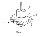
- the position sensor 6 is of the contactless type and, as shown in greater detail in figure 2 , consists of a magnetic dipole 7 fixed to a revolving free end 8 of the drive shaft 4, and a fixed reader 9 which is adapted to read the orientation of the magnetic dipole 7.
- the reader 9 is firmly connected to a supporting bracket (not shown), so as to arrange a front surface 10 of the reader 9 facing a surface 11 of the magnetic dipole 7.
- the bracket (not shown) is constructed so as to arrange the surface 10 at a predetermined distance from the magnetic dipole 7 and in a position axially and radially fixed with respect to the magnetic dipole 7.
- the position taken by the reader 9 with respect to the magnetic dipole 7 must be secure to prevent a drift of the position sensor 6 due to the variation over time of the relative position between the reader 9 and the magnetic dipole 7; specifically, it is particularly important to prevent a rotation between the reader 9 and the magnetic dipole 7 from occurring, while a limited variation of the reciprocal distance between the reader 9 and the magnetic dipole 7 may be tolerated.
- the position sensor 6 may be placed inside a housing box (not shown) for protecting and isolating the position sensor 6 itself.
- the internal combustion engine 1 further includes a control unit 12, which is connected to the position sensor 6 and is intended to process a digital electric signal output by the reader 9 which allows to determine at any time the absolute angular position of drive shaft 4, even upon starting the internal combustion engine 1.
- the reader 9 is an encoder which is the fixed part of the position sensor 6 and which contains therein the electronic components which are adapted to convert the angular position of the magnetic dipole 7 into electric output signals.
- the electric output signals transmit information related to the angular position and to the angular displacement of the magnetic dipole 7 with respect to the reader 9 itself.
- the reader 9 is able to supply indications about the angular position of the magnetic dipole 7 with a programmable bit resolution according to the calculating capacity of the control unit 12 and of the reader 9 for each complete revolution of the magnetic dipole 7.
- the electric output signals encode the exact instantaneous angular position of the magnetic dipole 7 with respect to the reader 9 itself, so that, at any time, an adequate decoding circuit inside the control unit 12 may identify the angular position of the magnetic dipole 7 itself.
- the data related to the displacement of the magnetic dipole 7 over time, and therefore the information related to the speed and the acceleration of the drive shaft 4, at the end of which the magnetic dipole 7 is fixed, are obtained by deriving the value of the angular position of the magnetic dipole 7 over the time.
- the reader 9 of the position sensor 6 outputs two digital electric signals consisting of two square waves A and B which are reciprocally offset by 90°, and a digital electric singularity signal C named "index".
- the control unit 12 is intended for processing the electric output signals of the position sensor 6 so as to select only either of the two output square waves A and B and to apply the "OR" logical operation between the selected wave A or B and the singularity signal C.
- the result is essentially a digital electric signal consisting of a square wave D, D' having a singularity which is generated by the "OR” logical operation between the selected square wave A or B and the singularity signal C and allows to determine the angular position of the drive shaft 4 by recognizing the singularity present in the digital signal D, D' itself.
- the square wave D, D' has a singularity output by the reader 9 of the position sensor 6 to the control unit 12 and which is completely similar to the square wave supplied by a traditional position sensor provided with a phonic wheel; therefore, the processing of the square wave D, D' output by the reader 9 of the position sensor 6 may be carried out by a control unit 12 of standard type without any change (except for those linked to the increase of measurement resolution).
- the reader 9 of the position sensor 6 generates a further digital electric signal consisting of a wave E having a width proportional to the absolute angular position of the magnetic dipole 7 with respect to the reader 9 by means of Pulse Width Modulation, more commonly referred to as PWM.
- PWM Pulse Width Modulation
- the absolute angular position of the magnetic dipole 7 with respect to the reader 9 (in the range between 0 and 360°) is digitally encoded in the form of time duration of height or start-up ("t on ") of each pulse of the wave E generated by the reader 9.
- the time duration of each pulse may be expressed in relation to the period between two subsequent pulses by means of the duty cycle concept; in the wave E, the duty cycle is the ratio between the time duration of height or start-up ("t on ") and the total period of the wave and is adapted to indicate for which fraction of the signal period the signal itself is high or on. If the duty cycle is equal to 10%, it means that the pulse has a zero duration of time and the absolute angular position of the magnetic dipole 7 with respect to the reader 9 is 0°, while if the duty cycle is equal to 90%, the absolute angular position of the magnetic dipole 7 with respect to the reader 9 is equal to 360°.
- the PWM signal values in the range between 0% and 10% and between 90% and 100% are commonly used for electric diagnosis of correct operation.
- the wave E containing the information about the absolute angular position of the magnetic dipole 7 with respect to the reader 9 is generated also when the magnetic dipole 7 is still.
- the wave E is also supplied by the reader 9 of the position sensor 6 to the control unit 12 which uses the wave E to determine the absolute angular position of the magnetic dipole 7 with respect to the reader 9.
- the control unit 12 uses the wave D, D' to determine the absolute angular position of the magnetic dipole 7.
- the wave D, D' is synchronous with the position of the magnetic dipole 7, i.e. the transitions of the leading/trailing edges of the wave D, D' are synchronous with the positions of the magnetic dipole 7.
- the wave E is instead not synchronous with the position of the magnetic dipole 7 because the constant frequency is generated.
- the combined processing of the two waves E and D, D' is used by the control unit 12 to determine the position of the engine and to speed up the operations of detecting the absolute position, because in virtue of the wave E it is no longer necessary to analyze the wave D, D' until the singularity is detected to know the absolute position of the engine.
- the reader 9 instead of generating the waves D, D' and E as digital electric output signals (shown in figure 3 ), generates a single wave F as digital electric output signal (shown in figure 4 ) in which all trailing edges (or, alternatively all leading edges) indicate the instants in which a same increase of the angular position of the magnetic dipole 7 occurs with respect to the reader 9 (i.e. they simulate the passage of the teeth of a traditional phonic wheel); e.g. between two consecutive trailing edges (or, alternatively between two consecutive leading edges) of the wave F the angular position of the magnetic dipole 7 with respect to the reader 9 is increased by a constant, predetermined amount (e.g. 4° or 6°).
- a constant, predetermined amount e.g. 4° or 6°
- the width of the wave F is proportional to the absolute angular position of the magnetic dipole 7 with respect to the reader 9 by means of a modulation for the width of a pulse; in other words, as described above, the absolute angular position of the magnetic dipole 7 with respect to the reader 9 (in the range between 0° and 360°) is digitally encoded in the form of time duration of height or start-up ("t on ") of each pulse of the wave F generated by the reader 9.
- control unit 12 uses the information modulated in the width of the pulse of the wave F and the sequences of trailing or leading edges to determine the absolute angular position of the magnetic dipole 7 with respect to the reader 9 when the magnetic dipole 7 is moving.
- the above-described modes for determining the angular position of the drive shaft 4 have many advantages because they are simple and cost-effective to be implemented, having very compact dimensions and do not require any particular modifications to the existing engine control units. Furthermore, the above-described modes for determining the angular position of the drive shaft 4 allow to reach very high resolutions (i.e. accuracies), theoretically down to fractions of degree, although such accuracies are not required because their use would exceed the calculation power limits of the current control units.
- very high resolutions i.e. accuracies
- the magnetic dipole 7 of the position sensor 6 is replaced by a wheel 13 fixed at the revolving free end 8 of the drive shaft 4 and is provided with a plurality of "teeth" consisting of corresponding magnetic dipoles fixed along the periphery of the wheel 13; such a wheel 13 is named “magnetic phonic wheel” and is completely similar to a traditional phonic wheel; in this embodiment, the reader 9 remains completely similar to the above-described reader 9 and is arranged facing the periphery of the magnetic phonic wheel 13.
- the reader 9 detects, in use, the variation of the magnetic field generated by the alternating of the magnetic dipoles arranged on the periphery of the magnetic phonic wheel 13.
- the magnetic dipoles which pass in front of a magnetic field generator cause a variation of the gap existing between the magnetic phonic wheel 13 and the reader 9.
- a square wave is thus induced in the reader 9 with an essentially high resolution which allows to obtain rather accurate information about the parameters of the drive shaft 4, such as for example speed, acceleration, etc.
- the magnetic phonic wheel 13 is required to be provided with a mechanical singularity, which represents the reference point of the magnetic phonic wheel 13 itself.
- the singularity is made in a manner completely similar as that for a phonic wheel of the traditional type, i.e. by removing two types of magnetic dipoles with which the magnetic phonic wheel 13 is provided.
- the two missing dipoles identify a range of width of approximately 12° which is a reference point of the drive shaft 4 for the position sensor 6.
- Each magnetic dipole of the magnetic phonic wheel 13 which follows the singularity transmits the increase of the angular position of the drive shaft 4 to the reader 9 until a 360° revolution and a new passage of the singularity are completed, both detected by the reader 9.
- the position sensor 6 is not able to recognize the absolute position of the drive shaft 4 until the first passage of the singularity, and furthermore, since the singularity is represented by a void, each revolution of the magnetic phonic wheel 13 corresponds to a 12° width range in which the position sensor 6 is blind, i.e. is able neither to detect any variations of the magnetic field nor to provide any indications about the speed of the drive shaft 4.
- the position sensor 6 allows to obtain precise information about the strength of the magnetic field generated by the alternating of magnetic dipoles, although it is able of provide indications only after the first detection of the singularity by the reader 9.
Landscapes
- Physics & Mathematics (AREA)
- General Physics & Mathematics (AREA)
- Measurement Of Length, Angles, Or The Like Using Electric Or Magnetic Means (AREA)
- Transmission And Conversion Of Sensor Element Output (AREA)
- Combined Controls Of Internal Combustion Engines (AREA)
Abstract
A unit and method of controlling an internal combustion engine (1), which is provided with a pivotally mounted drive shaft (4); the control unit has a position sensor (6) coupled to the drive shaft (4) for detecting the angular revolution speed of the drive shaft (4) itself; and a control unit (12), which is connected to the position sensor (6) and processes an output signal from the position sensor (6) itself for determining the angular position and the angular speed of the drive shaft (4); the position sensor (6) is in turn provided with a magnetic element (7), which is integral with a free end of the drive shaft (4), and with a reader (9) arranged in a fixed position facing the magnetic element (7) for reading the orientation of the magnetic element (7).
Description
- The present invention relates to a control unit and method for determining the angular position of a drive shaft of an internal combustion engine in an internal combustion engine.
- An internal combustion engine includes a number of cylinders and a corresponding number of pistons, each of which is slidingly accommodated inside a corresponding cylinder and transmits the motion to a drive shaft pivotally mounted by means of a rod-crank coupling. In a modern internal combustion engine, for controlling the fuel combustion inside the cylinders (i.e. for controlling the injection of fuel and for controlling, in controlled ignition engines, the ignition of the mixture), the instantaneous angular position of the drive shaft must be known in real time with the adequate accuracy (from which it is possible to further obtain the angular speed and the angular acceleration of the drive shaft by means of a simple time derivative operation).
- Position sensors of the "phonic wheel" type are used to determine the instantaneous angular position of the drive shaft in the currently marketed internal combustion engines; a position sensor of the "phonic wheel" type includes a toothed wheel (namely called "phonic wheel") which is provided with a plurality of teeth and is integral with the drive shaft, and a reader (e.g. of the inductive or Hall effect type) which is arranged in a fixed position close to the phonic wheel and is adapted to read the passage of each tooth of the phonic wheel. By counting the number of teeth of the phonic wheel by means of the reader, the relative angular position of the drive shaft may be determined; for determining the absolute angular position of the drive shaft, the phonic wheel is provided with a predetermined angular position of a singularity (typically two teeth missing from a 60 tooth wheel) which is known beforehand and recognized by the reader.
- A magnetic field generator (e.g. a permanent magnet) is arranged close to the reader and generates a magnetic field which hits the reader; the alternation of teeth and the voids of the phonic wheel determines cyclic variations in the intensity of the magnetic field which hits the reader modifying the gap existing between the magnetic field and the reader. Accordingly, the reader detects, in use, the variation of magnetic field generated by the alternating teeth and voids of the phonic wheel; then the reader outputs a square wave which represents the alternating of teeth and voids of the phonic wheel and has a void of larger dimensions (twice or three times normal) at the singularity of the phonic wheel. An electronic control unit of the internal combustion engine receives the square wave signal supplied by the position sensor reader and, by processing such a square wave signal, determines the absolute angular position, the average angular speed, the instantaneous angular speed, the instantaneous angular acceleration, and the direction of revolution of the drive shaft; specifically, the frequency and the width of the square wave signal supplied by the reader are proportional to the instantaneous angular speed of the drive shaft.
- In order to allow the reader to surely and accurately identify the alternating of teeth and voids of the phonic wheel, the teeth and voids of the phonic wheel itself must have a linear development which is not excessively small; accordingly, the higher the number of teeth which must be present in the phonic wheel (i.e. the higher the required angular resolution of the phonic wheel), the larger the diameter of the phonic wheel itself needs to be. Therefore, the size (and thus the resolution) of a phonic wheel must necessarily be an accommodation between the needs of accuracy and the needs to contain the mechanical inertia of the phonic wheel itself. In the currently marketed internal combustion engines, phonic wheels with a range of 6° between the beginning of one tooth and the beginning of the next tooth are used, so that sixty teeth are arranged on the periphery of the phonic wheel, except for the singularity, which represents the reference point made by removing two of the sixty teeth with which the phonic wheel is provided. In order to obtain resolutions higher than 6° it would be necessary to use larger phonic wheels, with a consequent great increase of the mechanical inertia of the phonic wheels themselves. It is worth noting that a phonic wheel provided with 60 teeth already has a non negligible size and may already have locating difficulties in the case of engines of small or very small capacity intended for very compact vehicles.
- Furthermore, upon starting the combustion engine, it is not possible to know the absolute angular position of the drive shaft until the first passage of the singularity of the phonic wheel in front of the reader; therefore, the engine control is not able to correctly control the fuel injection and, if required, the mixture ignition, at the first revolution of the drive shaft immediately after the start-up.
- Finally, since the singularity is represented by the two missing teeth, a 18° width range in which the sensor is blind, i.e. is not able to detect magnetic field variations and provide indications about the drive shaft speed, corresponds to each revolution of the phonic wheel; in other words, at the singularity, the resolution of the reader is of 18° and not 6° with the consequent considerable worsening of the position sensor accuracy. The need for obtaining information with a higher resolution, i.e. with a finer fractioning, is increasingly more felt, because the phonic wheel is able to provide information only every 6° and within this range the information may only be interpolated.
- It is the object of the present invention to provide a control unit and method for determining the angular position of a drive shaft of an internal combustion engine which are free from the above-described drawbacks and which are specifically easy and cost-effective to be implemented.
- According to the present invention, a control unit and method for determining the angular position of a drive shaft of an internal combustion engine are provided as disclosed in the appended claims.
- The present invention will now be described with reference to the accompanying drawings, which show a non-limitative embodiment thereof, in which:
-
figure 1 is a diagrammatic view of an internal combustion engine provided with a control unit constructed according to the present invention; -
figure 2 diagrammatically illustrates, on enlarged scale and with parts removed for clarity, a first embodiment of the position sensor of the control unit infigure 1 ; -
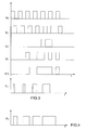
figure 3 is a graph which shows the time evolution of three digital electric signals generated by the position sensor infigure 2 and of two digital electric signals output by the position sensor infigure 2 ; -
figure 4 is a graph which shows the time evolution of a digital electric signal output by the position sensor infigure 2 according to a different embodiment; -
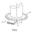
figure 5 diagrammatically illustrates, on enlarged scale and with parts removed for clarity, a second embodiment of the position sensor of the control unit infigure 2 . -
Figure 1 partially shows an internal combustion engine, which is indicated by numeral 1 as a whole. The internal combustion engine 1 includes fourcylinders 2, each of which slidingly accommodates acorresponding piston 3, which is mechanically connected to adrive shaft 4 by means of a rod-crank coupling; thedrive shaft 4 is pivotally mounted about alongitudinal revolution axis 5 and, from thepistons 3, receives the force generated by the combustion inside thecylinders 2. - The internal combustion engine 1 further includes a
position sensor 6 which reads the absolute angular position about thelongitudinal axis 5 of thedrive shaft 4 and determines the angular revolution speed of thedrive shaft 4 and a series of other parameters, including the instantaneous acceleration and the direction of revolution. - The
position sensor 6 is of the contactless type and, as shown in greater detail infigure 2 , consists of amagnetic dipole 7 fixed to a revolvingfree end 8 of thedrive shaft 4, and a fixed reader 9 which is adapted to read the orientation of themagnetic dipole 7. The reader 9 is firmly connected to a supporting bracket (not shown), so as to arrange afront surface 10 of the reader 9 facing asurface 11 of themagnetic dipole 7. The bracket (not shown) is constructed so as to arrange thesurface 10 at a predetermined distance from themagnetic dipole 7 and in a position axially and radially fixed with respect to themagnetic dipole 7. Importantly, the position taken by the reader 9 with respect to themagnetic dipole 7 must be secure to prevent a drift of theposition sensor 6 due to the variation over time of the relative position between the reader 9 and themagnetic dipole 7; specifically, it is particularly important to prevent a rotation between the reader 9 and themagnetic dipole 7 from occurring, while a limited variation of the reciprocal distance between the reader 9 and themagnetic dipole 7 may be tolerated. - With this regard, according to a further embodiment (not shown in the accompanying figures), the
position sensor 6 may be placed inside a housing box (not shown) for protecting and isolating theposition sensor 6 itself. - The internal combustion engine 1 further includes a
control unit 12, which is connected to theposition sensor 6 and is intended to process a digital electric signal output by the reader 9 which allows to determine at any time the absolute angular position ofdrive shaft 4, even upon starting the internal combustion engine 1. - The reader 9 is an encoder which is the fixed part of the
position sensor 6 and which contains therein the electronic components which are adapted to convert the angular position of themagnetic dipole 7 into electric output signals. The electric output signals transmit information related to the angular position and to the angular displacement of themagnetic dipole 7 with respect to the reader 9 itself. In this case, the reader 9 is able to supply indications about the angular position of themagnetic dipole 7 with a programmable bit resolution according to the calculating capacity of thecontrol unit 12 and of the reader 9 for each complete revolution of themagnetic dipole 7. - In the reader 9, the electric output signals encode the exact instantaneous angular position of the
magnetic dipole 7 with respect to the reader 9 itself, so that, at any time, an adequate decoding circuit inside thecontrol unit 12 may identify the angular position of themagnetic dipole 7 itself. The data related to the displacement of themagnetic dipole 7 over time, and therefore the information related to the speed and the acceleration of thedrive shaft 4, at the end of which themagnetic dipole 7 is fixed, are obtained by deriving the value of the angular position of themagnetic dipole 7 over the time. - As shown in
figure 3 , the reader 9 of theposition sensor 6 outputs two digital electric signals consisting of two square waves A and B which are reciprocally offset by 90°, and a digital electric singularity signal C named "index". Thecontrol unit 12 is intended for processing the electric output signals of theposition sensor 6 so as to select only either of the two output square waves A and B and to apply the "OR" logical operation between the selected wave A or B and the singularity signal C. The result is essentially a digital electric signal consisting of a square wave D, D' having a singularity which is generated by the "OR" logical operation between the selected square wave A or B and the singularity signal C and allows to determine the angular position of thedrive shaft 4 by recognizing the singularity present in the digital signal D, D' itself. It is worth noting that the waves A and B, the singularity signal C and thus the square wave D, D' are always generated, but are only meaningful when themagnetic dipole 7 is moving because, when themagnetic dipole 7 is still, all these digital electric signals constantly have the same value and therefore do not supply any useful indication. - Furthermore, it is worth noting that the square wave D, D' has a singularity output by the reader 9 of the
position sensor 6 to thecontrol unit 12 and which is completely similar to the square wave supplied by a traditional position sensor provided with a phonic wheel; therefore, the processing of the square wave D, D' output by the reader 9 of theposition sensor 6 may be carried out by acontrol unit 12 of standard type without any change (except for those linked to the increase of measurement resolution). - Furthermore, the reader 9 of the
position sensor 6 generates a further digital electric signal consisting of a wave E having a width proportional to the absolute angular position of themagnetic dipole 7 with respect to the reader 9 by means of Pulse Width Modulation, more commonly referred to as PWM. In other words, the absolute angular position of themagnetic dipole 7 with respect to the reader 9 (in the range between 0 and 360°) is digitally encoded in the form of time duration of height or start-up ("ton") of each pulse of the wave E generated by the reader 9. The time duration of each pulse may be expressed in relation to the period between two subsequent pulses by means of the duty cycle concept; in the wave E, the duty cycle is the ratio between the time duration of height or start-up ("ton") and the total period of the wave and is adapted to indicate for which fraction of the signal period the signal itself is high or on. If the duty cycle is equal to 10%, it means that the pulse has a zero duration of time and the absolute angular position of themagnetic dipole 7 with respect to the reader 9 is 0°, while if the duty cycle is equal to 90%, the absolute angular position of themagnetic dipole 7 with respect to the reader 9 is equal to 360°. The PWM signal values in the range between 0% and 10% and between 90% and 100% are commonly used for electric diagnosis of correct operation. - It is worth noting that the wave E containing the information about the absolute angular position of the
magnetic dipole 7 with respect to the reader 9 is generated also when themagnetic dipole 7 is still. - The wave E is also supplied by the reader 9 of the
position sensor 6 to thecontrol unit 12 which uses the wave E to determine the absolute angular position of themagnetic dipole 7 with respect to the reader 9. On the other hand, when themagnetic dipole 7 is moving, thecontrol unit 12 no longer uses the wave E, but uses the wave D, D' to determine the absolute angular position of themagnetic dipole 7. The wave D, D' is synchronous with the position of themagnetic dipole 7, i.e. the transitions of the leading/trailing edges of the wave D, D' are synchronous with the positions of themagnetic dipole 7. The wave E is instead not synchronous with the position of themagnetic dipole 7 because the constant frequency is generated. The combined processing of the two waves E and D, D' is used by thecontrol unit 12 to determine the position of the engine and to speed up the operations of detecting the absolute position, because in virtue of the wave E it is no longer necessary to analyze the wave D, D' until the singularity is detected to know the absolute position of the engine. - According to an alternative shown in
figure 4 , the reader 9, instead of generating the waves D, D' and E as digital electric output signals (shown infigure 3 ), generates a single wave F as digital electric output signal (shown infigure 4 ) in which all trailing edges (or, alternatively all leading edges) indicate the instants in which a same increase of the angular position of themagnetic dipole 7 occurs with respect to the reader 9 (i.e. they simulate the passage of the teeth of a traditional phonic wheel); e.g. between two consecutive trailing edges (or, alternatively between two consecutive leading edges) of the wave F the angular position of themagnetic dipole 7 with respect to the reader 9 is increased by a constant, predetermined amount (e.g. 4° or 6°). Furthermore, the width of the wave F is proportional to the absolute angular position of themagnetic dipole 7 with respect to the reader 9 by means of a modulation for the width of a pulse; in other words, as described above, the absolute angular position of themagnetic dipole 7 with respect to the reader 9 (in the range between 0° and 360°) is digitally encoded in the form of time duration of height or start-up ("ton") of each pulse of the wave F generated by the reader 9. - Similarly as illustrated above, the
control unit 12 uses the information modulated in the width of the pulse of the wave F and the sequences of trailing or leading edges to determine the absolute angular position of themagnetic dipole 7 with respect to the reader 9 when themagnetic dipole 7 is moving. - The above-described modes for determining the angular position of the
drive shaft 4 have many advantages because they are simple and cost-effective to be implemented, having very compact dimensions and do not require any particular modifications to the existing engine control units. Furthermore, the above-described modes for determining the angular position of thedrive shaft 4 allow to reach very high resolutions (i.e. accuracies), theoretically down to fractions of degree, although such accuracies are not required because their use would exceed the calculation power limits of the current control units. Finally, the above-described modes for determining the angular position of thedrive shaft 4 allow to accurately know the angular position of thedrive shaft 4 even when thedrive shaft 4 is still or as soon as the engine starts moving, thus the engine control upon starting the internal combustion engine 1 is much easier and more accurate. - According to a further embodiment shown in
figure 5 , themagnetic dipole 7 of theposition sensor 6 is replaced by awheel 13 fixed at the revolvingfree end 8 of thedrive shaft 4 and is provided with a plurality of "teeth" consisting of corresponding magnetic dipoles fixed along the periphery of thewheel 13; such awheel 13 is named "magnetic phonic wheel" and is completely similar to a traditional phonic wheel; in this embodiment, the reader 9 remains completely similar to the above-described reader 9 and is arranged facing the periphery of the magneticphonic wheel 13. - The reader 9 detects, in use, the variation of the magnetic field generated by the alternating of the magnetic dipoles arranged on the periphery of the magnetic
phonic wheel 13. The magnetic dipoles which pass in front of a magnetic field generator cause a variation of the gap existing between the magneticphonic wheel 13 and the reader 9. A square wave is thus induced in the reader 9 with an essentially high resolution which allows to obtain rather accurate information about the parameters of thedrive shaft 4, such as for example speed, acceleration, etc. - In this case, however, the magnetic
phonic wheel 13 is required to be provided with a mechanical singularity, which represents the reference point of the magneticphonic wheel 13 itself. The singularity is made in a manner completely similar as that for a phonic wheel of the traditional type, i.e. by removing two types of magnetic dipoles with which the magneticphonic wheel 13 is provided. The two missing dipoles identify a range of width of approximately 12° which is a reference point of thedrive shaft 4 for theposition sensor 6. - Each magnetic dipole of the magnetic
phonic wheel 13 which follows the singularity transmits the increase of the angular position of thedrive shaft 4 to the reader 9 until a 360° revolution and a new passage of the singularity are completed, both detected by the reader 9. - During the step of starting the internal combustion engine 1, the
position sensor 6 is not able to recognize the absolute position of thedrive shaft 4 until the first passage of the singularity, and furthermore, since the singularity is represented by a void, each revolution of the magneticphonic wheel 13 corresponds to a 12° width range in which theposition sensor 6 is blind, i.e. is able neither to detect any variations of the magnetic field nor to provide any indications about the speed of thedrive shaft 4. - It is therefore worth noting that, in this embodiment, the
position sensor 6 allows to obtain precise information about the strength of the magnetic field generated by the alternating of magnetic dipoles, although it is able of provide indications only after the first detection of the singularity by the reader 9.
Claims (13)
- A control unit of an internal combustion engine (1), which is provided with a pivotally mounted drive shaft (4); the control unit comprises:a position sensor (6) coupled to the drive shaft (4) for detecting the angular revolution speed of the drive shaft (4) itself; anda control unit (12), which is connected to the position sensor (6) and processes an output signal from the position sensor (6) itself for determining the angular position and the angular speed of the drive shaft (4);the control unit is characterized in that the position sensor (6) includes:a magnetic element (7, 13), which is integral with a free end of the drive shaft (4), anda reader (9), arranged in a fixed position facing the magnetic element (7, 13) for reading the orientation of the magnetic element (7, 13).
- A control unit according to claim 1, wherein the magnetic element (7) consists of a magnetic dipole (7) provided with a surface (11) facing a front surface (10) of the reader (9) at a given distance from the reader (9) itself.
- A control unit according to claim 1, wherein the magnetic element (13) consists of a wheel (13), which is provided with a plurality of magnetic dipoles distributed along the periphery of the wheel (13) itself and faces a front surface (10) of the reader (9) at a predetermined distance from the reader (9) itself.
- A control unit according to claim 3, wherein the wheel (12) is provided with a mechanical singularity made by removing at least one magnetic dipole arranged on the periphery of the wheel itself.
- A control unit according to anyone of the claims from 1 to 4, wherein the magnetic element (7, 13) and the reader (9) are arranged inside a housing box, which is adapted to protect and isolate the magnetic element (7) and the reader (9).
- A control method of an internal combustion engine (1), which is provided with a pivotally mounted drive shaft (4); the control method includes the steps of:coupling a magnetic element (7) to a free end of the drive shaft (4);reading, by means of a reader (9) arranged in a fixed position facing the magnetic element (7), the orientation of the magnetic element (7) itself; anddetermining the angular position and the angular speed of the drive shaft (4) by means of a control unit (12), which is connected to the reader (9) and processes an output signal from the reader (9) itself.
- A control method according to claim 6, and including the further steps of:outputting at least one first digital electric signal (A; B) from the sensor (9), which signal consists of a square wave, the leading and/or trailing edges of which indicate constant, predetermined increases in the angular position of the magnetic element (7); andoutputting a second digital electric signal (C) of singularity from the reader (9), which signal consists of a square wave having a leading edge at a predetermined angular position of the magnetic element (7) and the trailing edge which may be programmed according to a predetermined angular width.
- A control method according to claim 7, and including a further step of generating a third digital electric output signal (D, D') consisting of a square wave generated by an "OR" logical operation between the first digital electric signal (A; B) and the second digital electric signal (C) of singularity.
- A method according to claim 8, and including the further step of outputting two first digital electric signals (A, B) from the reader (9), which signals consist of two square waves reciprocally offset by 90°.
- A method according to claim 8 or 9, and including the further step of generating a fourth digital electric signal (E) consisting of a square wave having a proportional width to the absolute angular position of the magnetic element (7) with respect to the sensor (9).
- A method according to claim 10, and including the further steps of:determining the absolute angular position of the magnetic element (7) by means of the combined analysis of the third digital electric output signal (D, D') and of the fourth digital electric signal (E).
- A control method according to claim 7, and including the further step of generating a fifth digital electric output signal (F) consisting of a square wave, wherein each leading or trailing edge of the square wave represents a given increase of the angular position of the magnetic element (7) with respect to the reader (9); the signal (F) further having a proportional width to the absolute angular position of the magnetic element (7) with respect to the reader (9) by means of a pulse width modulation, so that the absolute angular position of the magnetic element (7) with respect to the reader (9) is digitally encoded in the form of time duration of height or start-up ("ton") of each pulse of the fifth digital electric output signal (F) generated by the reader (9).
- A control method according to claim 12, wherein the increase of the angular position of the magnetic element (7) with respect to the reader (9) is constant and depends on the resolution of the reader (9); each angular position being detected by the trailing or leading edges of the fifth digital electric output signal (F) to prevent the resolution from being lost close to the singularity.
Priority Applications (2)
| Application Number | Priority Date | Filing Date | Title |
|---|---|---|---|
| EP08425593A EP2161547A1 (en) | 2008-09-05 | 2008-09-05 | Control unit and method for determining the angular position of a drive shaft of an internal combustion engine |
| EP09151470.3A EP2161548A3 (en) | 2008-09-05 | 2009-01-27 | A control unit and method for determining the angular position of a drive shaft of an internal combustion engine |
Applications Claiming Priority (1)
| Application Number | Priority Date | Filing Date | Title |
|---|---|---|---|
| EP08425593A EP2161547A1 (en) | 2008-09-05 | 2008-09-05 | Control unit and method for determining the angular position of a drive shaft of an internal combustion engine |
Publications (1)
| Publication Number | Publication Date |
|---|---|
| EP2161547A1 true EP2161547A1 (en) | 2010-03-10 |
Family
ID=40635835
Family Applications (2)
| Application Number | Title | Priority Date | Filing Date |
|---|---|---|---|
| EP08425593A Withdrawn EP2161547A1 (en) | 2008-09-05 | 2008-09-05 | Control unit and method for determining the angular position of a drive shaft of an internal combustion engine |
| EP09151470.3A Withdrawn EP2161548A3 (en) | 2008-09-05 | 2009-01-27 | A control unit and method for determining the angular position of a drive shaft of an internal combustion engine |
Family Applications After (1)
| Application Number | Title | Priority Date | Filing Date |
|---|---|---|---|
| EP09151470.3A Withdrawn EP2161548A3 (en) | 2008-09-05 | 2009-01-27 | A control unit and method for determining the angular position of a drive shaft of an internal combustion engine |
Country Status (1)
| Country | Link |
|---|---|
| EP (2) | EP2161547A1 (en) |
Cited By (4)
| Publication number | Priority date | Publication date | Assignee | Title |
|---|---|---|---|---|
| US9488498B2 (en) | 2014-03-21 | 2016-11-08 | Infineon Technologies Ag | Cam shaft rotation sensor |
| US10222234B2 (en) | 2014-06-17 | 2019-03-05 | Infineon Technologies Ag | Rotation sensor |
| US11125768B2 (en) | 2014-06-17 | 2021-09-21 | Infineon Technologies Ag | Angle based speed sensor device |
| CN115917131A (en) * | 2020-07-16 | 2023-04-04 | 大陆汽车科技有限公司 | Magnetic sensors for vehicle drive shafts |
Citations (5)
| Publication number | Priority date | Publication date | Assignee | Title |
|---|---|---|---|---|
| GB2328752A (en) * | 1997-08-30 | 1999-03-03 | Bosch Gmbh Robert | A device for angular measurement and angular coordination. |
| DE10034927A1 (en) * | 2000-07-18 | 2002-02-07 | Infineon Technologies Ag | Magnetic sensor arrangement for internal combustion engine, has magnet and sensor that measure current rotational angle of crankshaft or cam shaft based on change in magnetic field direction |
| DE10261612A1 (en) * | 2002-12-27 | 2003-12-11 | Bosch Gmbh Robert | Rotational velocity measurement device, e.g. for a motor vehicle combustion engine component, has a magnetic pole wheel and a field sensor with at least one sensor unit operating as a spin valve sensor |
| FR2858849A1 (en) * | 2003-08-15 | 2005-02-18 | Freudenberg Carl Kg | Multipole magnetic encoder for internal combustion engine, has marking section that is limited from two sides of non magnetized central zone by magnetic poles in form of strips and of same polarization |
| DE102005027654A1 (en) * | 2005-06-15 | 2006-12-21 | Robert Bosch Gmbh | Sensor for position detection when starting an internal combustion engine |
Family Cites Families (3)
| Publication number | Priority date | Publication date | Assignee | Title |
|---|---|---|---|---|
| DE19750024B4 (en) * | 1997-11-12 | 2008-05-15 | Robert Bosch Gmbh | Method for determining an attachment error of a sensor wheel and method for controlling the fuel metering of an internal combustion engine |
| US6131547A (en) * | 1998-02-27 | 2000-10-17 | Cummins Engine Company, Inc. | Electronic engine speed and position apparatus for camshaft gear applications |
| ATE461426T1 (en) * | 2006-11-17 | 2010-04-15 | Amo Automatisierung Messtechni | POSITION MEASURING DEVICE |
-
2008
- 2008-09-05 EP EP08425593A patent/EP2161547A1/en not_active Withdrawn
-
2009
- 2009-01-27 EP EP09151470.3A patent/EP2161548A3/en not_active Withdrawn
Patent Citations (5)
| Publication number | Priority date | Publication date | Assignee | Title |
|---|---|---|---|---|
| GB2328752A (en) * | 1997-08-30 | 1999-03-03 | Bosch Gmbh Robert | A device for angular measurement and angular coordination. |
| DE10034927A1 (en) * | 2000-07-18 | 2002-02-07 | Infineon Technologies Ag | Magnetic sensor arrangement for internal combustion engine, has magnet and sensor that measure current rotational angle of crankshaft or cam shaft based on change in magnetic field direction |
| DE10261612A1 (en) * | 2002-12-27 | 2003-12-11 | Bosch Gmbh Robert | Rotational velocity measurement device, e.g. for a motor vehicle combustion engine component, has a magnetic pole wheel and a field sensor with at least one sensor unit operating as a spin valve sensor |
| FR2858849A1 (en) * | 2003-08-15 | 2005-02-18 | Freudenberg Carl Kg | Multipole magnetic encoder for internal combustion engine, has marking section that is limited from two sides of non magnetized central zone by magnetic poles in form of strips and of same polarization |
| DE102005027654A1 (en) * | 2005-06-15 | 2006-12-21 | Robert Bosch Gmbh | Sensor for position detection when starting an internal combustion engine |
Cited By (8)
| Publication number | Priority date | Publication date | Assignee | Title |
|---|---|---|---|---|
| US9488498B2 (en) | 2014-03-21 | 2016-11-08 | Infineon Technologies Ag | Cam shaft rotation sensor |
| US10222234B2 (en) | 2014-06-17 | 2019-03-05 | Infineon Technologies Ag | Rotation sensor |
| US10718633B2 (en) | 2014-06-17 | 2020-07-21 | Infineon Technologies Ag | Rotation sensor |
| US11125768B2 (en) | 2014-06-17 | 2021-09-21 | Infineon Technologies Ag | Angle based speed sensor device |
| US11359936B2 (en) | 2014-06-17 | 2022-06-14 | Infineon Technologies Ag | Rotation sensor |
| US11733260B2 (en) | 2014-06-17 | 2023-08-22 | Infineon Technologies Ag | Angle based speed sensor device |
| CN115917131A (en) * | 2020-07-16 | 2023-04-04 | 大陆汽车科技有限公司 | Magnetic sensors for vehicle drive shafts |
| CN115917131B (en) * | 2020-07-16 | 2025-09-19 | 大陆汽车科技有限公司 | Magnetic sensor for vehicle drive shaft |
Also Published As
| Publication number | Publication date |
|---|---|
| EP2161548A3 (en) | 2016-03-30 |
| EP2161548A2 (en) | 2010-03-10 |
Similar Documents
| Publication | Publication Date | Title |
|---|---|---|
| CN110177999B (en) | Sensor wheel assembly and method for acquiring absolute angular position and rotational direction | |
| US9739228B2 (en) | Method for communicating a malfunction of a system for measuring speed and direction of rotation of a rotary shaft | |
| CN103528602B (en) | Encoder | |
| US20040089272A1 (en) | Crank angle detection apparatus | |
| CN104975966A (en) | Method for determining a rotational speed | |
| CN104319947B (en) | Motor with residual magnetization detection sensor and method for measuring revolution and/or angle thereof | |
| US20200103250A1 (en) | Sensor system for determining at least one rotational characteristic of an element rotating about at least one axis of rotation | |
| CN111433568B (en) | Sensor system for determining at least one rotation characteristic of a rotating element rotating about at least one axis of rotation | |
| CN102359755B (en) | Method for detecting pitch error of ABS gear ring by magnetic induction | |
| US20210159822A1 (en) | Method for determining an angular position of a rotating component, in particular of an electric motor for a clutch actuation system of a vehicle | |
| US20170292855A1 (en) | Multipole Magnet for Use With A Pitched Magnetic Sensor | |
| CN102053165B (en) | Systems and method for measuring vehicle speed | |
| CN104975961A (en) | Method for determining a crankshaft position of an internal combustion engine | |
| US10401194B2 (en) | Sensor for determining at least one rotation characteristic of a rotating element | |
| CN102893132B (en) | A device and a method for processing signals which represent an angular position of a motor shaft | |
| JP4662674B2 (en) | Method and apparatus for identifying misconnection in signal generator | |
| CN112880725B (en) | Method for judging total pitch deviation of position sensor | |
| EP2161548A2 (en) | A control unit and method for determining the angular position of a drive shaft of an internal combustion engine | |
| CN100451555C (en) | Method for the transmission of angle information and apparatus implementing the method | |
| KR900004779B1 (en) | Timing signal generator for rotating device | |
| CN102410806A (en) | Device for detecting pitch error of ABS gear ring by magnetic induction | |
| CN113847935B (en) | Position determining method and device for hybrid encoder | |
| US6615644B2 (en) | Method for correcting the signal of a camshaft position sensor | |
| EP2058628A2 (en) | Method and apparatus to monitor position of a rotatable shaft | |
| EP2163856B1 (en) | Method for determining the angular position of a drive shaft of an internal combustion engine |
Legal Events
| Date | Code | Title | Description |
|---|---|---|---|
| PUAI | Public reference made under article 153(3) epc to a published international application that has entered the european phase |
Free format text: ORIGINAL CODE: 0009012 |
|
| AK | Designated contracting states |
Kind code of ref document: A1 Designated state(s): AT BE BG CH CY CZ DE DK EE ES FI FR GB GR HR HU IE IS IT LI LT LU LV MC MT NL NO PL PT RO SE SI SK TR |
|
| AX | Request for extension of the european patent |
Extension state: AL BA MK RS |
|
| AKY | No designation fees paid | ||
| REG | Reference to a national code |
Ref country code: DE Ref legal event code: 8566 |
|
| STAA | Information on the status of an ep patent application or granted ep patent |
Free format text: STATUS: THE APPLICATION IS DEEMED TO BE WITHDRAWN |
|
| 18D | Application deemed to be withdrawn |
Effective date: 20100911 |