EP2161179A1 - Electric power steering device - Google Patents
Electric power steering device Download PDFInfo
- Publication number
- EP2161179A1 EP2161179A1 EP08740736A EP08740736A EP2161179A1 EP 2161179 A1 EP2161179 A1 EP 2161179A1 EP 08740736 A EP08740736 A EP 08740736A EP 08740736 A EP08740736 A EP 08740736A EP 2161179 A1 EP2161179 A1 EP 2161179A1
- Authority
- EP
- European Patent Office
- Prior art keywords
- checking
- steering
- steering assisting
- ignition switch
- state
- Prior art date
- Legal status (The legal status is an assumption and is not a legal conclusion. Google has not performed a legal analysis and makes no representation as to the accuracy of the status listed.)
- Granted
Links
Images




Classifications
-
- B—PERFORMING OPERATIONS; TRANSPORTING
- B62—LAND VEHICLES FOR TRAVELLING OTHERWISE THAN ON RAILS
- B62D—MOTOR VEHICLES; TRAILERS
- B62D5/00—Power-assisted or power-driven steering
- B62D5/04—Power-assisted or power-driven steering electrical, e.g. using an electric servo-motor connected to, or forming part of, the steering gear
- B62D5/0457—Power-assisted or power-driven steering electrical, e.g. using an electric servo-motor connected to, or forming part of, the steering gear characterised by control features of the drive means as such
-
- B—PERFORMING OPERATIONS; TRANSPORTING
- B62—LAND VEHICLES FOR TRAVELLING OTHERWISE THAN ON RAILS
- B62D—MOTOR VEHICLES; TRAILERS
- B62D5/00—Power-assisted or power-driven steering
- B62D5/04—Power-assisted or power-driven steering electrical, e.g. using an electric servo-motor connected to, or forming part of, the steering gear
- B62D5/0457—Power-assisted or power-driven steering electrical, e.g. using an electric servo-motor connected to, or forming part of, the steering gear characterised by control features of the drive means as such
- B62D5/0481—Power-assisted or power-driven steering electrical, e.g. using an electric servo-motor connected to, or forming part of, the steering gear characterised by control features of the drive means as such monitoring the steering system, e.g. failures
Definitions
- the present invention relates to an electric power steering apparatus comprising a steering assisting mechanism that is provided with an electric motor to give steering assisting power to a steering system, a steering assisting control means that controls driving the steering assisting mechanism, and a self-checking means that performs initial checking including checking of a power interruption means at the start of the operation of the steering assisting control means and that makes the steering assisting control means to be energized state to operate the power interruption means, when there is no trouble in operation of the steering assisting control means in a result of the initial checking.
- an electric power steering apparatus that a control unit turns off a power supply relay and a motor relay respectively after the elapse of a delay time set beforehand since an ignition switch is turned off, and when the ignition switch is turned on again before the elapse of the delay time, the control unit makes an assist start condition (number of rotations of engine NE> 470rpm) set beforehand to be an input waiting state without performing initial checking, thereby preventing an assist start delay after the ignition switch is turned on again as the assist start is possible immediately when the ignition switch is turned on again before the elapse of the delay time (refer to patent document 1).
- an assist start condition number of rotations of engine NE> 470rpm
- the present invention has been made in view of the unsolved problems of the prior art examples and has an object to provide an electric power steering apparatus that can prevent a sonic boom from causing while shortening the initial checking time when the ignition switch is turned to on state again before the elapse of the predetermined delay time since the ignition switch is turned to off state.
- An electric power steering apparatus is characterized in that an electric power steering apparatus comprising: a steering assisting mechanism that is provided with an electric motor to give a steering assisting force to a steering system; a steering assisting control means that controls driving the electric motor of the steering assisting mechanism; and a self-checking means that performs an initial checking including a checking of a power interruption means of the steering assisting control means at least when an ignition switch is turned to on state, and that causes the steering assisting control means to operate when there is no trouble in operation of the steering assisting control means in a result of the initial checking, wherein the self-checking means is configured to determine checking items to be executed in the next initial checking on the basis of a checking result in a period until the ignition switch is turned to off state since the steering assisting control means operates.
- the self-checking performs initial checking for every operation start of steering assisting control means, however, checking items in performing initial checking are determined on the basis of a result of checking in a period until the ignition switch is turned to off state since the steering assisting control means operates at previous time. Therefore, it is possible to shorten initial checking time by performing only necessary initial checking.
- the self-checking means is configured to execute the initial checking when the ignition switch is turned to on state, and perform the initial checking for checking items except the checking items accompanying with conduction/interruption operations of the power interruption means when the ignition switch is turned to on state again before the elapse of the predetermined delay time to maintain the steering assisting control means in operation state since the ignition switch is turned to off state.
- the self-checking means performs the initial checking for checking items except the checking items accompanying with conduction/interruption operations of the power interruption means such as a relay when the ignition switch is turned to on state again before the elapse of the predetermined delay time to maintain the steering assisting control means in operation state since the ignition switch is turned to off state. Therefore, it is possible to prevent surely a sonic boom at the time of conduction operation and interruption operation of power interruption means from occurring.
- the power interruption means is controlled in operation by a control means comprising a power supply system from a power supply source except a power supply system from the ignition switch.
- the power interruption means is controlled in operation by a control means comprising a power supply system from a power supply source except a power supply system from the ignition switch. Therefore, even if the ignition switch is turned to off state, it is possible to continue an operation control of power interruption means can be continued by the control means.
- the steering assisting control means comprises an arithmetical processing unit that operates a current command value on the basis of a steering torque input from the steering torque detection means; a motor control unit that drives the electric motor on the basis of the current command value operated in the arithmetical processing unit; a power interruption means that supplies a power from the power supply unit to the motor control unit; and a motor relay that is interposed between the motor control means and the electric motor, and a power circuit that is connected between the power interruption means and motor control unit while being connected to the power supply source via the ignition switch for supplying the operation power to the arithmetical processing unit.
- the power circuit includes two of power supply systems with a power supply system via an ignition switch and a power supply system via power interruption means. Therefore, it is possible to operate the arithmetical processing unit because the power supply circuit operates until the power supply interruption means is turned power interruption state so that initial checking processing corresponding to the initial checking means is executed by this arithmetical processing unit, thereby allowing to take operational advantages similar with claim 3.
- FIG. 1 is a schematic block diagram showing one embodiment according to the present invention.
- 1 denotes a steering wheel, and a steering force acted by a driver to this steering wheel 1 is transmitted to a steering shaft 2 having an input shaft 2a and an output shaft 2b.
- this steering shaft 2 one end of the input shaft 2a is coupled to the steering wheel 1, and another end thereof, is coupled via the steering torque sensor 3 as a steering torque detection means, to one end of the output shaft 2b.
- the steering torque sensor 3 consists of a main torque sensor 3m and a sub torque sensor 3s.
- the steering force transmitted to the output shaft 2b is transmitted via an universal joint 4 to a lower shaft 5, and is additionally transmitted via an universal joint 6 to a pinion shaft 7.
- the steering force transmitted to this pinion shaft 7 is transmitted via a steering gear mechanism 8 to a tie rod 9, and makes a turning-steered wheel, which is not illustrated, to be turning-steered.
- the steering gear mechanism 8 is constituted in a rack-and-pinion form to have a pinion 8a coupled to the pinion shaft 7 and a rack 8b engaging with this pinion 8a, and convert a rotation movement transmitted to the pinion 8a to a linear movement at the rack 8b.
- a steering assisting mechanism 10 for transmitting a steering assisting force to the output shaft 2b is coupled to the output shaft 2b of the steering shaft 2.
- This steering assisting mechanism 10 includes a reduction gear 11 coupled to the output shaft 2b and an electric motor 13, as a electric motor generating the steering assisting force, coupled to the reduction gear 11.
- the main torque sensor 3m and the sub torque sensor 3s constituting the steering torque sensor 3 are provided on the steering wheel 1 to detect a steering torque transmitted to the input shaft 2a and are, for example, configured to convert the steering torque to a distortion angular displacement of the torsion bar, which is not illustrated, interposed between the input shat 2a and the output shaft 2b, and convert this distortion angular displacement to a resistance change or a magnetic change so as to detect the steering torque.
- These main torque sensor 3m and sub torque sensor 3s are configured to output the torque detection values Tm and Ts which become a predetermined neutral voltage V 0 when the input steering torque is zero, which become a more increased voltage than the neutral voltage V 0 in accordance with the increment of the steering torque when steering to right from the situation that steering torque is zero, and which become a more decreased voltage than the neutral voltage V 0 in accordance with the increment of the steering torque when steering to left from the situation that the torque is zero.
- the torque detection values Tm and Ts output by these main torque sensor 3m and sub torque sensor 3s are input to a control unit 14.
- a power is supplied via an ignition switch 16 from a battery 15 as a power supply source, and a power is supplied directly from the battery 15, vehicle speed detection value Vs detected by a vehicle speed sensor 17 and drive current detection value Im flowing into the electric motor 13 are also input to, other than the torque detection values Tm and Ts.
- a steering assisting command value Iref is calculated that occurs the steering assisting force corresponding to the input torque detection value Tm and the vehicle detection value Vs in the electric motor 13, and a drive current supplied to the electric motor 13 is feedback-controlled on the basis of the calculated steering assisting command value Iref and motor current detection value Im.
- the control unit 14, as shown in FIG.3 includes a torque detection circuit 21 in which the torque detection signals of main torque sensor 3m and sub torque sensor 3s constituting the steering torque sensor 3 are input so that plus and minus torque detection values Tm and Ts are calculated by subtracting the neutral voltage V 0 from these input torque detection signals.
- This torque detection circuit 21 includes therein a sensor voltage monitoring section 21a which monitors whether or not the sensor voltage supplied to both torque sensors 3m and 3s is normal, and outputs a voltage abnormality detection signal SA of, for example, logic value "1" when the sensor voltage is abnormal.
- control unit 14 includes an arithmetical processing unit 22 constituted in, for example, a CPU which performs a predetermined operation on the basis of the torque detection values Tm and Ts output from the torque detection circuit 21, the voltage abnormality detection signal SA and vehicle detection value Vs to output motor control signal Imr.
- This arithmetical processing unit 22 is supplied with a control electric power generated by a power supply circuit 23 which has two types of power supply systems: a power supply system in which a power from the battery 15 is supplied via the ignition switch 16; and a power supply system in which a power is supplied from an output side of the power supply relay described below.
- the arithmetical processing unit 22 is coupled to the bus 25 as a transmission path constituting a controller area network (CAN: Controller Area Network) via a communication interface circuit 24 and obtains vehicle detection value Vs from the vehicle speed sensor 17 which is coupled to the bus 25.
- the arithmetical processing unit 22 is coupled to a motor current detection circuit 26 which detects a motor current on the basis of the difference in the electric potentials between the both ends of a shunt resistance Rs interposed into an H bridge circuit described below, is also coupled to the motor terminal voltage detection circuit 27 which detects a motor terminal voltage of the electric motor 13, and is further coupled to a temperature detection circuit 28 which detects a temperature near the arithmetical processing unit 22.
- the arithmetical processing unit 22 is coupled to a non-volatile memory 29 which is constituted in, for example, an EEPROM for storing a checking result detected in a self-checking processing described below, and is further coupled to an alarm circuit 32 which issues an alarm of alarming sound or alarming display in a case where the checking result includes abnormality making it impossible to execute a steering assisting control.
- a non-volatile memory 29 which is constituted in, for example, an EEPROM for storing a checking result detected in a self-checking processing described below, and is further coupled to an alarm circuit 32 which issues an alarm of alarming sound or alarming display in a case where the checking result includes abnormality making it impossible to execute a steering assisting control.
- the arithmetical processing unit 22 has a main MCU (Micro Controller Unit) 101 and a sub MCU 102.
- the main MCU 101 has therein a watch-dog timer (WDT) 101m for self-monitoring to monitor mutually and a watch-dog timer (WDT) 101s for sub MCU.
- the sub MCU 102 also has therein a watch-dog timer (WDT) 102s for self-monitoring to monitor mutually and a watch-dog timer (WDT) 102m for main MCU.
- the sub MCU 102 determines that the main CPU 101 is abnormal due to an over flow of the program, or the like, outputs motor drive prohibition signal Mp to an FET drive circuit 31 described below to stop driving the electric motor 13, and outputs a relay control signal Cp to turn the power supply relay 34 as a power interruption means off state.
- Both of the main MCU 101 and the sub MCU 102 generate a motor driving signal Imr on the basis of torque detection values Tm and Ts, vehicle detection value Vs, motor current detection value Im, and motor terminal voltage Vm.
- the sub MCU 102 compares the motor driving signal Imr calculated by the sub MCU 102 with the motor driving signal Imr calculated by the main MCU 101, and determines that if the deviation of both is within a predetermined range, the main CPU 101 is normal.
- the sub MCU 102 determines that if the deviation is out of the predetermined range, the main CPU 101 is abnormal, and outputs motor drive prohibition signal Mp to the FET drive circuit 31 and outputs off signal to the power supply relay 34.
- the main MCU 101 has therein at least, a ROM (Read On Memory) 130 storing a steering assisting control processing program executed in both MCUs, a self-checking processing program, or the like, and a RAM (Random Access Memory) 131 storing detection data of the torque detection values Tm and Ts, vehicle detection value Vs, motor current detection value Imd, and motor terminal voltage detection value Vmd, or the like, and data or processing result to be needed in processing of the steering assisting control processing and self-checking processing executed in MCU.
- ROM Read On Memory
- RAM Random Access Memory
- the sub MCU 102 has therein at least, a ROM 130 storing a steering assisting control processing program, or the like, and a RAM 131 storing data or processing result to be needed in processing of the steering assisting control processing, or the like executed in MCU.
- step S1 torque detection value Tm detected in the main torque sensor 3m from the steering torque detection circuit 21, and vehicle speed detection value Vs detected in the vehicle speed sensor 17 are read, then the process proceeds to step S2, the motor current detection value Imd and the motor terminal voltage detection value Vmd are read, and then the process proceeds to step S3, steering assisting command value Iref to become a motor current command value is calculated with referring to the steering assisting command value calculation map shown in FIG.5 on the basis of torque detection value Tm and vehicle detection value Vs.
- the steering assisting command value calculation map consists of torque detection value Tm taken in the horizontal axis, steering assisting torque command value Iref taken in the vertical axis, and characteristic diagram represented by a parabolic curve with making vehicle speed detection value Vs as a parameter.
- the steering assisting torque command value Iref maintains "0" between the torque detection vale Tm "0" and set value Ts1 near “0", and is set so that, when the torque detection value Tm exceeds set value Ts1, at first the steering assisting command value Iref increases comparatively-gently with respect to an increment of torque detection value Tm, but when torque detection value Tm further increases, steering assisting torque command value Iref increases steeply with respect to its increment.
- the inclination of this characteristic curve is set to become small in accordance with the increment of the vehicle speed.
- step S4 an operation of following expression (1) is performed, on the basis of motor current detection value Imd and the motor terminal voltage detection value Vmd, to calculate motor angular velocity ⁇ .
- ⁇ Vmd - Imd ⁇ Rm / K 0
- Rm denotes a motor windings resistance
- K 0 denotes an electromotive force constant of a motor.
- a code of friction compensation value If is determined by a code of the torque detection value Tm and by steering direction signals for determining operation-increase/operation-returning of steering by this torque detection value Tm.
- step S6 torque detection value Tm is processed by differential operation to calculate center responsive improvement command value Ir that secures stability in an assist characteristic dead band and compensates for static friction.
- step S8 steering assisting compensation value Iref' is differentiated to calculate differential value Id for feed forward control.
- step S9 motor current detection value Imd is subtracted from steering assisting compensation value Iref' to calculate electric current deviation ⁇ I.
- step S10 electric current deviation ⁇ I is processed by proportion operation to calculate proportion value ⁇ Ip for proportion compensation control.
- step S13 motor driving current Imr calculated in step S12 and rotating direction signal Dm that corresponds to a code of plus or minus of this motor driving current Imr are output to the FET drive circuit 31 controlling field effect transistors FET1 to FET4 constituting an H bridge circuit 30 driving the electric motor 13.
- the H bridge circuit 30 has a serial circuit in which two field effect transistors FET1 and FET2 are serially-connected, and a serial circuit in which two field effect transistors FET3 and FET4 are serially-connected in parallel with a former serial circuit.
- the electric motor 13 is connected via a motor relay 33 between a connection point of field effect transistors FET1 and FET2 and a connection point of field effect transistors FET3 and FET4, and one of connection points of both serial circuits is connected via the power supply relay 34 to the battery 15 and the other is grounded via shunt resistor Rs.
- the FET drive circuit 31 performs pulse width modulation on the basis of the motor driving current Imr, when motor driving current Imr and rotating direction signal Dm are input from the main MCU 101, to form pulse width modulation pulse PWM of a duty ratio that corresponds to motor driving current Imr, and determines which group is selected, on the basis of rotating direction signal Dm, from between a group of field effect transistors FET1 and FET4 and a group of field effect transistors FET2 and FET3, on a diagonal of the H bridge circuit 30, and supplies on status signal for controlling one selected group of field effect transistors, for example, FET1 or FET3 to on state, and supplies a pulse width modulation signal PWM to the other group of field effect transistors FET2 and FET4.
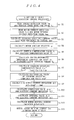
- step S21 it is determined whether or not initial checking completion flag F, which represents whether or not an execution of an initial checking is completed, is set to "1" that represents initial checking completion.
- initial checking completion flag F is reset to "0"
- the process proceeds to step S22, and all of initial checking items set beforehand are executed.
- initial checking items are set as follows: torque sensor checking processing that operates absolute value
- relay checking processing controls relay control signals Cm and Cp for the motor relay 33 and the power supply relay 34 to on state and off state, and read respectively output voltages when the motor relay 33 and the power supply relay 34 are made to be bias state and non bias state, to check a welding state of the relay connection point.
- step S23 initial checking completion flag F is set to "1"
- step S24 it is determined whether or not there is no abnormality in an initial checking result, and when there is no abnormality in the initial checking result, the process proceeds to step S29, and when there is any abnormality in the initial checking result, the process proceeds to step S25, and the checking result that abnormality occurred is stored in the nonvolatile memory 29.
- step S26 it is determined whether or not steering assisting control is possible from the checking result that abnormality occurred, and when steering assisting control is impossible, the process proceeds to step S27, and a severe alarm signal representing an event that steering assisting control is impossible is output to an alarm circuit 32, and then self-checking processing is finished, and when steering assisting control is possible, the process proceeds to step S28, and a minor alarm signal representing an event of minor abnormality is output to the alarm circuit 32, and then the process proceeds to step S29.
- step S29 relay control signals Cm and Cp, which turn the motor relay 33 and the power supply relay 34 on state, are output to make steering assisting control waiting state, subsequently the process proceeds to step S30, and it is determined whether or not a predetermined steering assisting start condition is satisfied.
- this steering assisting start condition it is determined whether or not the number of rotations (RPM) of engine became a predetermined value (for example, 470rpm) set beforehand, or more, and when the steering assistance start condition is satisfied, the process proceeds to step S31, and steering assisting control processing previously described in FIG.4 is started, and then the process proceeds to step S32, and steering assisting control in-processing flag FA representing that steering assisting control processing is being executed, to set "1" representing that steering assisting control processing is being processed, and then the process proceeds to step S36.
- RPM number of rotations
- step S30 when steering assisting control start condition is not satisfied, the process proceeds to step S33, and it is determined whether or not steering assisting control in-processing flag FA is set to "1", and when steering assisting control in-processing flag FA is reset to "0", the process proceeds to step S36 directly, and when steering assisting control in-processing flag FA is set to "1", the process proceeds to step S34, and steering assisting control processing is finished, subsequently the process proceeds to step S35, and steering assisting control in-processing flag FA is reset to "0", and then the process proceeds to step S36.
- step S36 it is determined whether or not the ignition switch 16 is turned to off state, and when the ignition switch 16 continues on state, the process proceeds to step S37, and it is determined whether or not steering assisting control in-processing flag FA is set to "1", and when steering assisting control in-processing flag FA is reset to "0", the process proceeds is turned back to step S30, and when steering assisting control in-processing flag FA is reset to "1", the process proceeds to step S38, and an abnormality checking processing in a normal state is executed, and then the process proceeds to step S39.
- the abnormality checking processing in this normal state executes torque sensor checking processing, power supply checking processing, controller abnormality processing, motor terminal voltage checking processing, motor current checking processing, overcurrent checking processing and motor checking processing, among checking items of initial checking processing previously described.
- step S39 it is determined whether or not there is no abnormality in checking result in above step S38, and when there is no abnormally, the process proceeds is turned back to step S36, and when there is any abnormality, the process proceeds to step S40, and the abnormality result is stored in the nonvolatile memory 29, and steering assisting control processing of FIG. 4 is finished, and then the process proceeds to step S43 described below.
- step S41 the process proceeds to step S41, so that steering assisting control processing of FIG. 4 is finished, and then the process proceeds to step S42, to determine whether or not a predetermined delay time (for example, 10 minutes) set beforehand has been passed since the ignition switch 16 is turned to off state.
- a predetermined delay time for example, 10 minutes
- the process proceeds to step S43, and relay control signals Cm and Cp which turn the motor relay 33 and the power supply relay 34 off state together are output, and then self-checking processing is finished, and when the predetermined delay time has not elapsed, the process proceeds to step S44.
- step S44 it is determined whether or not the ignition switch 16 is turned to on state again, and when the ignition switch 16 continues off state, the process is turned back to step S42, and when the ignition switch 16 is returned on state again, the process is turned back to step S21.
- step S45 so as to execute initial checking processing for remaining checking items except relay checking processing and controller checking processing executed in step S21, subsequently the process proceeds to step S46, and checking result determination processing similar with steps S24 to step S28 previously described, and when there is no abnormality in checking result, or in a case even if there is any abnormality, it is a minor abnormality, the process proceeds to step S30, and turns steering assisting control waiting state, and when abnormality to affect steering assisting control occurred, the abnormality is stored in the nonvolatile memory 29, and an alarm signal is output to the alarm circuit 32, and then the process proceeds to step S43.
- This processing of FIG.4 corresponds to steering assisting control means
- FIG.6 corresponds to self-checking means.
- step S21 initial checking completion flag F is reset to "0"
- initial checking processing performing checking of all initial checking items, including torque sensor checking processing, power supply checking processing, controller checking processing, temperature detection checking processing, motor terminal voltage checking processing, motor current checking processing, checking processing of main MCU, overcurrent checking processing, motor checking processing, relay checking processing and CAM checking processing previously described, is executed.
- step S24 initial checking completion flag F is set to "1". Subsequently the process proceeds to step S24, and it is determined whether or not there is no abnormality in initial checking result.
- the checking result that abnormality occurred is stored in the nonvolatile memory 29 except abnormality of the nonvolatile memory 29 (step S25), subsequently it is determined whether or not steering assisting control is possible, and in a case torque sensor abnormality, power supply abnormality, motor terminal voltage abnormality, motor current abnormality, abnormality of the main MCU 101, overcurrent abnormality, motor abnormality, relay abnormality are detected, normal steering assisting control cannot be performed, accordingly it is determined that steering assisting control is impossible and the process proceeds to step S27, and an abnormality alarm signal representing that steering assisting control is impossible, is output to the alarm circuit 32, and after alarming an effect that steering assisting control is impossible to a driver, and self-checking processing is finished.
- steering assisting control processing of FIG. 4 is not started, and the motor relay 33 and the power supply relay 34 maintain off state. Therefore, the electric motor 13 maintains stop state without being driven and the steering wheel 1 is steered only by a steering force of the driver.
- a minor abnormality signal representing an effect that it is minor abnormality is output to the alarm circuit 32, and then the process proceeds to step S29.
- the process proceeds to step S29 directly.
- step S30 it is determined whether or not steering assisting control start condition set beforehand is satisfied, and when steering assisting control start condition is not satisfied, the process proceeds to step S33, and it is determined whether or not steering assisting control in-processing flag FA is "1", Since the steering assisting control is not started and steering assisting control in-processing flag FA is reset to "0", the process proceeds step S36 directly, and it is determined whether or not the ignition switch 16 is turned to off state. In a case the ignition switch 16 continues on state, the process proceeds to step S37, and because steering assisting control in-processing flag FA is reset to "0", the process is turned back to step S30, and steering assisting control waiting state is continued.
- step S30 when a steering assisting control start condition is satisfied, the process proceeds from step S30 to step S31, and steering assisting control processing of FIG.4 is started. Subsequently, the process proceeds to step S32, and steering assisting control in-processing flag FA is set to "1", and then the process proceeds to step S36, and it is determined whether or not the ignition switch 16 is turned to off state.
- step S1 torque detection value Tm detected at main torque sensor 3m of the steering torque sensor 3 and vehicle speed detection value Vs detected in the vehicle speed sensor 17 are read (step S1), subsequently motor current detection value Imd and motor terminals voltage detection value Vmd are read (step S2), and steering assistance command value Iref is calculated with reference to steering assisting command value calculation map shown in FIG. 5 , on the basis of torque detection value Tm and vehicle speed detection value Vs (step S3).
- step S4 previously described expression (1) is operated on the basis of motor current detection value Imd and motor terminal voltage detection value Vmd, to calculate motor angular velocity ⁇ (step S4), and simultaneously inertia compensation value Ii for inertia compensation control is calculated on the basis of this motor angular velocity ⁇ , friction compensation value If for friction compensation control is calculated (step S5).
- steering torque Tm is processed by differential operation to calculate center responsive improvement command value Ir (step S6). Then, these inertia compensation value Ii, friction compensation value If and center responsive improvement compensation value Ir are added to steering assisting command value Iref to calculate steering assisting compensation value Iref' (step S7).
- steering assisting compensation value Iref' is processed by differential operation to calculate differential value Id for differential compensation control in feed forward control (step S8).
- motor current detection value Imd is subtracted from steering assisting compensation value Iref' to calculate electric current deviation ⁇ I (step S9),
- Such calculated electric current deviation ⁇ I is processed by proportion operation to calculate proportion value ⁇ Ip for proportion compensation control and simultaneously, is processed by integral operation to calculate integral value ⁇ Ii for integral compensation control (steps S10 and S11).
- differential value Id, proportion value ⁇ Ip and integral value ⁇ Ii are added to calculate motor driving signal Imr (step S12).
- calculated motor driving signal Imr is output to the FET drive circuit 31, so that control signal in on state and pulse width modulated pulse PWM are supplied to field effect transistors FET1 and FET4 or FET3 and FET2 on a diagonal of an H bridge 30 from the FET drive circuit 31, whereby a drive current is supplied to the electric motor 13 to generate steering assisting force corresponding to steering torque acted to the steering wheel 1, and to transmit this force via the reduction gear to the output shaft 2b.
- step S36 when a driver stops a vehicle and turns the ignition switch 16 off state, the process proceeds from step S36 to step S41 in self-checking processing of FIG.6 , and steering assisting control processing of FIG.4 is finished. Subsequently the process proceeds to step S42, and it is determined whether or not predetermined delay time passed. When the predetermined delay time has not passed, the process proceeds to step S44, and it is determined whether or not the ignition switch 16 is turned to on state again.
- step S43 relay control signals Cm and Cp that turn the motor relay 33 and the power supply relay 34 off state are output to turn the motor relay 33 and the power supply relay 34 off state, whereby power supply from the battery 15 to the power supply circuit 23 is interrupted so that power supply to the arithmetical processing unit 22, the H bridge circuit 30, the FET drive circuit 31 and the electric motor 13 is interrupted.
- step S24 Initial checking processing of checking items, except relay checking processing and checking processing to prohibit steering assistance with the power supply relay 34 turned off state by the sub MCU 102, among initial checking items, is executed, and then the process proceeds to step S24.
- step S30 it is determined whether or not steering assisting control start condition is satisfied, and when steering assisting control start condition is satisfied, the process proceeds to step S30, and steering assisting control processing is started to be returned in a steering assisting control state.
- relay checking processing is removed in initial checking processing to be executed in step S23. Accordingly, a sonic boom to become an impact noise by turning the motor relay 33 and the power supply relay 34 to on or off individually by relay checking processing, can be prevented surely from occurring multiple times, and can be prevented from giving uncomfortable feeling to a driver to improve its merchantability, and can remove relay checking processing that takes much time to shorten an initial checking time. Besides, because checking processing is performed for checking items except relay checking processing, necessary initial checking can be performed while shortening an initial checking time.
- checking items can be determined when the ignition switch 16 is turned to on state again on the basis of checking result executed in a period until the ignition switch 16 is turned to off state since the ignition switch 16 is turned to on state.
- abnormality detection flags FT and FM representing abnormality of the temperature detection circuit 28 and abnormality of the nonvolatile memory 29 at that time are set to "1" to be stored in a predetermined storage area of RAM or an external memory.
- the ignition switch 16 is turned to on state again, the presence or absence of abnormality detection flags FT and FM is confirmed with reference to the predetermined storage area of a RAM or an external memory in initial checking processing of step S23, so that initial checking may be performed only for checking items in which abnormality detection flag is stored.
- motor driving current Imr is calculated with software processing to perform in the arithmetical processing unit 22, but the present invention is not limited to this.
- the motor driving current Imr may be calculated with hardware in which a steering assisting command value operation unit, a center responsive improvement circuit, an inertia compensator, a friction compensator, a differential compensator, a subtractor, a proportion operation unit, an integral operation unit, an adder, and the like may be combined together.
- the above embodiment is described for a case that an EEPROM is applied as the nonvolatile memory 29, but the present mention is not limited to this.
- Arbitrary nonvolatile memory such as a flash memory can be applied.
- the above embodiment is described for a case that the arithmetical processing unit 22 is constituted of two of the main MCU 101 and the sub MCU 102, but the present mention is not limited to this, operation processing may be performed by one MCU or an arithmetical processing unit corresponding to MCU.
- initial checking is performed in self-checking means for every operation start of steering assisting control means, but checking items in performing this initial checking are determined on the basis of checking result in a period until the ignition switch is turned to off state since operating steering assisting control means operates at a previous time. Therefore, only necessary initial checking may be performed to shorten initial checking time.
Landscapes
- Engineering & Computer Science (AREA)
- Chemical & Material Sciences (AREA)
- Combustion & Propulsion (AREA)
- Transportation (AREA)
- Mechanical Engineering (AREA)
- Steering Control In Accordance With Driving Conditions (AREA)
- Power Steering Mechanism (AREA)
- Motor And Converter Starters (AREA)
Abstract
Description
- The present invention relates to an electric power steering apparatus comprising a steering assisting mechanism that is provided with an electric motor to give steering assisting power to a steering system, a steering assisting control means that controls driving the steering assisting mechanism, and a self-checking means that performs initial checking including checking of a power interruption means at the start of the operation of the steering assisting control means and that makes the steering assisting control means to be energized state to operate the power interruption means, when there is no trouble in operation of the steering assisting control means in a result of the initial checking.
- As this kind of electric power steering apparatus heretofore, for example, an electric power steering apparatus is known that a control unit turns off a power supply relay and a motor relay respectively after the elapse of a delay time set beforehand since an ignition switch is turned off, and when the ignition switch is turned on again before the elapse of the delay time, the control unit makes an assist start condition (number of rotations of engine NE> 470rpm) set beforehand to be an input waiting state without performing initial checking, thereby preventing an assist start delay after the ignition switch is turned on again as the assist start is possible immediately when the ignition switch is turned on again before the elapse of the delay time (refer to patent document 1).
- [patent document 1]
JP 2003-182598A - However, in the conventional embodiment as described in
above patent document 1, when the ignition switch is turned to on state again before the elapse of the predetermined delay time since the ignition switch is turned to off state, an assist start condition is set to be input waiting state without initial checking. Therefore there is an unsolved problem that an abnormality occurring after the initial checking in previous on state of the ignition switch cannot be detected. - In order to solve this problem, it is necessary to perform the initial checking for every time the ignition switch is turned to on state. However, in a case of checking of a power interruption means such as a relay in this initial checking is performed, it is necessary to return the power interruption means to on state after once turning it off state to ensure a conduction state. However, there is a problem that time is needed for this checking, and an abnormal sound occurs when turning the power interruption means to on state, so that an aggravation of merchantability is caused.
- Thus, the present invention has been made in view of the unsolved problems of the prior art examples and has an object to provide an electric power steering apparatus that can prevent a sonic boom from causing while shortening the initial checking time when the ignition switch is turned to on state again before the elapse of the predetermined delay time since the ignition switch is turned to off state.
- An electric power steering apparatus according to the present invention is characterized in that an electric power steering apparatus comprising: a steering assisting mechanism that is provided with an electric motor to give a steering assisting force to a steering system; a steering assisting control means that controls driving the electric motor of the steering assisting mechanism; and a self-checking means that performs an initial checking including a checking of a power interruption means of the steering assisting control means at least when an ignition switch is turned to on state, and that causes the steering assisting control means to operate when there is no trouble in operation of the steering assisting control means in a result of the initial checking,
wherein the self-checking means is configured to determine checking items to be executed in the next initial checking on the basis of a checking result in a period until the ignition switch is turned to off state since the steering assisting control means operates. - According to this configuration, the self-checking performs initial checking for every operation start of steering assisting control means, however, checking items in performing initial checking are determined on the basis of a result of checking in a period until the ignition switch is turned to off state since the steering assisting control means operates at previous time. Therefore, it is possible to shorten initial checking time by performing only necessary initial checking.
In addition, the self-checking means is configured to execute the initial checking when the ignition switch is turned to on state, and perform the initial checking for checking items except the checking items accompanying with conduction/interruption operations of the power interruption means when the ignition switch is turned to on state again before the elapse of the predetermined delay time to maintain the steering assisting control means in operation state since the ignition switch is turned to off state. - According to this configuration, the self-checking means performs the initial checking for checking items except the checking items accompanying with conduction/interruption operations of the power interruption means such as a relay when the ignition switch is turned to on state again before the elapse of the predetermined delay time to maintain the steering assisting control means in operation state since the ignition switch is turned to off state. Therefore, it is possible to prevent surely a sonic boom at the time of conduction operation and interruption operation of power interruption means from occurring.
- In addition, the power interruption means is controlled in operation by a control means comprising a power supply system from a power supply source except a power supply system from the ignition switch.
According to this configuration, the power interruption means is controlled in operation by a control means comprising a power supply system from a power supply source except a power supply system from the ignition switch. Therefore, even if the ignition switch is turned to off state, it is possible to continue an operation control of power interruption means can be continued by the control means. - Furthermore, the steering assisting control means comprises an arithmetical processing unit that operates a current command value on the basis of a steering torque input from the steering torque detection means; a motor control unit that drives the electric motor on the basis of the current command value operated in the arithmetical processing unit; a power interruption means that supplies a power from the power supply unit to the motor control unit; and a motor relay that is interposed between the motor control means and the electric motor, and a power circuit that is connected between the power interruption means and motor control unit while being connected to the power supply source via the ignition switch for supplying the operation power to the arithmetical processing unit.
- According to this configuration, the power circuit includes two of power supply systems with a power supply system via an ignition switch and a power supply system via power interruption means. Therefore, it is possible to operate the arithmetical processing unit because the power supply circuit operates until the power supply interruption means is turned power interruption state so that initial checking processing corresponding to the initial checking means is executed by this arithmetical processing unit, thereby allowing to take operational advantages similar with
claim 3. -
-
FIG.1 is a schematic block diagram showing one embodiment according to the present invention; -
FIG. 2 is a characteristic diagram illustrative of torque detection signals detected by a steering torque sensor; -
FIG.3 is a block diagram illustrative of a concrete configuration of a controller ofFIG. 1 ; -
FIG.4 is a flow chart illustrative of an example of a steering assisting control processing procedure to be executed in a main MCU and a sub MCU; -
FIG.5 is a characteristic diagram illustrative of a steering assisting command value calculation map; and -
FIG.6 is a flow chart illustrative of an example of a self-checking processing procedure to be executed in the main MCU. - Embodiments of the present invention will now be described with reference to the accompanying drawings.
FIG. 1 is a schematic block diagram showing one embodiment according to the present invention. InFIG.1, 1 denotes a steering wheel, and a steering force acted by a driver to thissteering wheel 1 is transmitted to asteering shaft 2 having aninput shaft 2a and anoutput shaft 2b. In thissteering shaft 2, one end of theinput shaft 2a is coupled to thesteering wheel 1, and another end thereof, is coupled via thesteering torque sensor 3 as a steering torque detection means, to one end of theoutput shaft 2b. Here, thesteering torque sensor 3 consists of amain torque sensor 3m and asub torque sensor 3s. - The steering force transmitted to the
output shaft 2b is transmitted via anuniversal joint 4 to alower shaft 5, and is additionally transmitted via anuniversal joint 6 to apinion shaft 7. The steering force transmitted to thispinion shaft 7 is transmitted via asteering gear mechanism 8 to atie rod 9, and makes a turning-steered wheel, which is not illustrated, to be turning-steered. Here, thesteering gear mechanism 8 is constituted in a rack-and-pinion form to have apinion 8a coupled to thepinion shaft 7 and arack 8b engaging with thispinion 8a, and convert a rotation movement transmitted to thepinion 8a to a linear movement at therack 8b. - A
steering assisting mechanism 10 for transmitting a steering assisting force to theoutput shaft 2b is coupled to theoutput shaft 2b of thesteering shaft 2. Thissteering assisting mechanism 10 includes areduction gear 11 coupled to theoutput shaft 2b and anelectric motor 13, as a electric motor generating the steering assisting force, coupled to thereduction gear 11.
Themain torque sensor 3m and thesub torque sensor 3s constituting thesteering torque sensor 3 are provided on thesteering wheel 1 to detect a steering torque transmitted to theinput shaft 2a and are, for example, configured to convert the steering torque to a distortion angular displacement of the torsion bar, which is not illustrated, interposed between theinput shat 2a and theoutput shaft 2b, and convert this distortion angular displacement to a resistance change or a magnetic change so as to detect the steering torque. - These
main torque sensor 3m andsub torque sensor 3s, as shown inFIG. 2 , are configured to output the torque detection values Tm and Ts which become a predetermined neutral voltage V0 when the input steering torque is zero, which become a more increased voltage than the neutral voltage V0 in accordance with the increment of the steering torque when steering to right from the situation that steering torque is zero, and which become a more decreased voltage than the neutral voltage V0 in accordance with the increment of the steering torque when steering to left from the situation that the torque is zero. - The torque detection values Tm and Ts output by these
main torque sensor 3m andsub torque sensor 3s are input to acontrol unit 14. In thiscontrol unit 14, a power is supplied via anignition switch 16 from abattery 15 as a power supply source, and a power is supplied directly from thebattery 15, vehicle speed detection value Vs detected by avehicle speed sensor 17 and drive current detection value Im flowing into theelectric motor 13 are also input to, other than the torque detection values Tm and Ts. Thus, a steering assisting command value Iref is calculated that occurs the steering assisting force corresponding to the input torque detection value Tm and the vehicle detection value Vs in theelectric motor 13, and a drive current supplied to theelectric motor 13 is feedback-controlled on the basis of the calculated steering assisting command value Iref and motor current detection value Im. - The
control unit 14, as shown inFIG.3 , includes atorque detection circuit 21 in which the torque detection signals ofmain torque sensor 3m andsub torque sensor 3s constituting thesteering torque sensor 3 are input so that plus and minus torque detection values Tm and Ts are calculated by subtracting the neutral voltage V0 from these input torque detection signals. Thistorque detection circuit 21 includes therein a sensorvoltage monitoring section 21a which monitors whether or not the sensor voltage supplied to bothtorque sensors - In addition, the
control unit 14 includes anarithmetical processing unit 22 constituted in, for example, a CPU which performs a predetermined operation on the basis of the torque detection values Tm and Ts output from thetorque detection circuit 21, the voltage abnormality detection signal SA and vehicle detection value Vs to output motor control signal Imr. Thisarithmetical processing unit 22 is supplied with a control electric power generated by apower supply circuit 23 which has two types of power supply systems: a power supply system in which a power from thebattery 15 is supplied via theignition switch 16; and a power supply system in which a power is supplied from an output side of the power supply relay described below. - In addition, the
arithmetical processing unit 22 is coupled to thebus 25 as a transmission path constituting a controller area network (CAN: Controller Area Network) via acommunication interface circuit 24 and obtains vehicle detection value Vs from thevehicle speed sensor 17 which is coupled to thebus 25.
In addition, thearithmetical processing unit 22 is coupled to a motorcurrent detection circuit 26 which detects a motor current on the basis of the difference in the electric potentials between the both ends of a shunt resistance Rs interposed into an H bridge circuit described below, is also coupled to the motor terminalvoltage detection circuit 27 which detects a motor terminal voltage of theelectric motor 13, and is further coupled to atemperature detection circuit 28 which detects a temperature near thearithmetical processing unit 22. In addition, thearithmetical processing unit 22 is coupled to anon-volatile memory 29 which is constituted in, for example, an EEPROM for storing a checking result detected in a self-checking processing described below, and is further coupled to analarm circuit 32 which issues an alarm of alarming sound or alarming display in a case where the checking result includes abnormality making it impossible to execute a steering assisting control. - Furthermore the
arithmetical processing unit 22 has a main MCU (Micro Controller Unit) 101 and asub MCU 102. The main MCU 101 has therein a watch-dog timer (WDT) 101m for self-monitoring to monitor mutually and a watch-dog timer (WDT) 101s for sub MCU. Thesub MCU 102 also has therein a watch-dog timer (WDT) 102s for self-monitoring to monitor mutually and a watch-dog timer (WDT) 102m for main MCU. Thus when time of a watch-dog timer 102m for the main MCU is up, thesub MCU 102 determines that themain CPU 101 is abnormal due to an over flow of the program, or the like, outputs motor drive prohibition signal Mp to anFET drive circuit 31 described below to stop driving theelectric motor 13, and outputs a relay control signal Cp to turn thepower supply relay 34 as a power interruption means off state. - Both of the
main MCU 101 and thesub MCU 102 generate a motor driving signal Imr on the basis of torque detection values Tm and Ts, vehicle detection value Vs, motor current detection value Im, and motor terminal voltage Vm. However, only the motor driving signal Imr from themain MCU 101 is input to theFET drive circuit 31 described below and the motor driving signal Imr calculated by thesub MCU 102 is used for monitoring. Therefore, thesub MCU 102 compares the motor driving signal Imr calculated by thesub MCU 102 with the motor driving signal Imr calculated by themain MCU 101, and determines that if the deviation of both is within a predetermined range, themain CPU 101 is normal. However thesub MCU 102 determines that if the deviation is out of the predetermined range, themain CPU 101 is abnormal, and outputs motor drive prohibition signal Mp to theFET drive circuit 31 and outputs off signal to thepower supply relay 34. - Here, the
main MCU 101, as shown inFIG. 3 , has therein at least, a ROM (Read On Memory) 130 storing a steering assisting control processing program executed in both MCUs, a self-checking processing program, or the like, and a RAM (Random Access Memory) 131 storing detection data of the torque detection values Tm and Ts, vehicle detection value Vs, motor current detection value Imd, and motor terminal voltage detection value Vmd, or the like, and data or processing result to be needed in processing of the steering assisting control processing and self-checking processing executed in MCU. In addition, thesub MCU 102 has therein at least, aROM 130 storing a steering assisting control processing program, or the like, and aRAM 131 storing data or processing result to be needed in processing of the steering assisting control processing, or the like executed in MCU. - In addition, in the steering assisting control processing executed in the
main MCU 101 and thesub MCU 102, as shown inFIG.4 , at first in step S1, torque detection value Tm detected in themain torque sensor 3m from the steeringtorque detection circuit 21, and vehicle speed detection value Vs detected in thevehicle speed sensor 17 are read, then the process proceeds to step S2, the motor current detection value Imd and the motor terminal voltage detection value Vmd are read, and then the process proceeds to step S3, steering assisting command value Iref to become a motor current command value is calculated with referring to the steering assisting command value calculation map shown inFIG.5 on the basis of torque detection value Tm and vehicle detection value Vs. - Here, as shown in
FIG.5 , the steering assisting command value calculation map consists of torque detection value Tm taken in the horizontal axis, steering assisting torque command value Iref taken in the vertical axis, and characteristic diagram represented by a parabolic curve with making vehicle speed detection value Vs as a parameter. The steering assisting torque command value Iref maintains "0" between the torque detection vale Tm "0" and set value Ts1 near "0", and is set so that, when the torque detection value Tm exceeds set value Ts1, at first the steering assisting command value Iref increases comparatively-gently with respect to an increment of torque detection value Tm, but when torque detection value Tm further increases, steering assisting torque command value Iref increases steeply with respect to its increment. The inclination of this characteristic curve is set to become small in accordance with the increment of the vehicle speed. - Subsequently, the process proceeds to step S4, and an operation of following expression (1) is performed, on the basis of motor current detection value Imd and the motor terminal voltage detection value Vmd, to calculate motor angular velocity ω.

Here, Rm denotes a motor windings resistance, and K0 denotes an electromotive force constant of a motor.
Subsequently, the process proceeds to step S5, and motor angular velocity ω is multiplied by inertia gain Ki, and a torque which accelerates or decelerates a motor inertia is removed from the steering torque Tm to calculate inertia compensation value Ii (= Ki · ω) for inertia compensation control to get steering sense having no inertia feeling, and friction coefficient gain Kf is multiplied by absolute value of steering assisting command value Tref, to calculate friction compensation value If (Kf · Iref) for friction compensation control to eliminate effecting to steering force by friction for power transmission or electric motor. Here, a code of friction compensation value If is determined by a code of the torque detection value Tm and by steering direction signals for determining operation-increase/operation-returning of steering by this torque detection value Tm. - Subsequently, the process proceeds to step S6, and torque detection value Tm is processed by differential operation to calculate center responsive improvement command value Ir that secures stability in an assist characteristic dead band and compensates for static friction. And the process proceeds to step S7, and the calculated inertia compensation value Ii, friction compensation value If and center responsive improvement command value Ir are added to steering assistance command value Iref to calculate steering assistance compensation value Iref' (= Iref+Ii+If+Ir). Subsequently the process proceeds to step S8, and steering assisting compensation value Iref' is differentiated to calculate differential value Id for feed forward control.
- Subsequently, the process proceeds to step S9, and motor current detection value Imd is subtracted from steering assisting compensation value Iref' to calculate electric current deviation ΔI. Subsequently the process proceeds to step S10, and electric current deviation ΔI is processed by proportion operation to calculate proportion value ΔIp for proportion compensation control. Subsequently the process proceeds to step S11, and electric current deviation ΔI is processed by integral operation to calculate integral value ΔIi for integral compensation control, subsequently the process proceeds to step S12, and differential value Id, proportion value ΔIp and integral value ΔIi are added to calculate motor driving current Imr (=Id+ΔIp+ΔIi), and the process proceeds to step S13.
- In this step S13, motor driving current Imr calculated in step S12 and rotating direction signal Dm that corresponds to a code of plus or minus of this motor driving current Imr are output to the
FET drive circuit 31 controlling field effect transistors FET1 to FET4 constituting anH bridge circuit 30 driving theelectric motor 13.
TheH bridge circuit 30 has a serial circuit in which two field effect transistors FET1 and FET2 are serially-connected, and a serial circuit in which two field effect transistors FET3 and FET4 are serially-connected in parallel with a former serial circuit. Theelectric motor 13 is connected via a motor relay 33 between a connection point of field effect transistors FET1 and FET2 and a connection point of field effect transistors FET3 and FET4, and one of connection points of both serial circuits is connected via thepower supply relay 34 to thebattery 15 and the other is grounded via shunt resistor Rs. - The
FET drive circuit 31 performs pulse width modulation on the basis of the motor driving current Imr, when motor driving current Imr and rotating direction signal Dm are input from themain MCU 101, to form pulse width modulation pulse PWM of a duty ratio that corresponds to motor driving current Imr, and determines which group is selected, on the basis of rotating direction signal Dm, from between a group of field effect transistors FET1 and FET4 and a group of field effect transistors FET2 and FET3, on a diagonal of theH bridge circuit 30, and supplies on status signal for controlling one selected group of field effect transistors, for example, FET1 or FET3 to on state, and supplies a pulse width modulation signal PWM to the other group of field effect transistors FET2 and FET4. - In addition, in the
main MCU 101, self-checking processing shown inFIG. 6 is executed.
This self-checking processing is started for execution when a power is supplied from thepower supply circuit 23 into thearithmetical processing unit 22 with theignition switch 16 turned on state. At first, in step S21, it is determined whether or not initial checking completion flag F, which represents whether or not an execution of an initial checking is completed, is set to "1" that represents initial checking completion. When initial checking completion flag F is reset to "0", the process proceeds to step S22, and all of initial checking items set beforehand are executed. Here, initial checking items are set as follows: torque sensor checking processing that operates absolute value |ΔT| of deviation ΔT of torque detection values Tm and Ts to determine whether or not this absolute value |ΔT| is a predetermined value ΔTs or more, and determine that torque sensor is abnormal when |ΔT" ≧ ΔTs and determines that torque sensor is abnormal when voltage abnormality detection signal SA is logic value "1"; power supply checking processing that detects abnormality of power supply voltage of the power supply circuit 23, battery voltage of the battery 15, and battery voltage input via the ignition switch 16; controller checking processing that detects abnormality of the main MCU 101 by the sub MCU 102; nonvolatile memory checking processing that detects abnormality of the nonvolatile memory 29 connected to the main MCU 101; temperature detection checking processing that detects abnormality of the temperature around the arithmetical processing unit 22 on the basis of temperature detection value of the temperature detection circuit 28; motor terminal voltage checking processing that detects abnormality of motor terminal voltage detected in the motor terminal voltage detection circuit 27; motor current checking processing that detects abnormality of motor current detection value Imd detected in motor current detection circuit 26; checking processing of the main MCU 101; overcurrent checking processing that detects overcurrent abnormality due to abnormality such as a earth fault, powering fault and short circuit of the H bridge circuit 30 and the FET drive circuit 31; motor checking processing that detects abnormality of the electric motor 13; relay checking processing that detects abnormality of the motor relay 33 and the power supply relay 34; and CAN checking processing that detects abnormality of CAN communication.
Here, relay checking processing controls relay control signals Cm and Cp for the motor relay 33 and thepower supply relay 34 to on state and off state, and read respectively output voltages when the motor relay 33 and thepower supply relay 34 are made to be bias state and non bias state, to check a welding state of the relay connection point. - When this initial checking processing is completed, the process proceeds to step S23, and initial checking completion flag F is set to "1", subsequently the process proceeds to step S24, and it is determined whether or not there is no abnormality in an initial checking result, and when there is no abnormality in the initial checking result, the process proceeds to step S29, and when there is any abnormality in the initial checking result, the process proceeds to step S25, and the checking result that abnormality occurred is stored in the
nonvolatile memory 29.
And then the process proceeds to step S26, and it is determined whether or not steering assisting control is possible from the checking result that abnormality occurred, and when steering assisting control is impossible, the process proceeds to step S27, and a severe alarm signal representing an event that steering assisting control is impossible is output to analarm circuit 32, and then self-checking processing is finished, and when steering assisting control is possible, the process proceeds to step S28, and a minor alarm signal representing an event of minor abnormality is output to thealarm circuit 32, and then the process proceeds to step S29. - In step S29, relay control signals Cm and Cp, which turn the motor relay 33 and the
power supply relay 34 on state, are output to make steering assisting control waiting state, subsequently the process proceeds to step S30, and it is determined whether or not a predetermined steering assisting start condition is satisfied. As this steering assisting start condition, it is determined whether or not the number of rotations (RPM) of engine became a predetermined value (for example, 470rpm) set beforehand, or more, and when the steering assistance start condition is satisfied, the process proceeds to step S31, and steering assisting control processing previously described inFIG.4 is started, and then the process proceeds to step S32, and steering assisting control in-processing flag FA representing that steering assisting control processing is being executed, to set "1" representing that steering assisting control processing is being processed, and then the process proceeds to step S36. - On the other hand, in the determination result of step S30, when steering assisting control start condition is not satisfied, the process proceeds to step S33, and it is determined whether or not steering assisting control in-processing flag FA is set to "1", and when steering assisting control in-processing flag FA is reset to "0", the process proceeds to step S36 directly, and when steering assisting control in-processing flag FA is set to "1", the process proceeds to step S34, and steering assisting control processing is finished, subsequently the process proceeds to step S35, and steering assisting control in-processing flag FA is reset to "0", and then the process proceeds to step S36.
- In step S36, it is determined whether or not the
ignition switch 16 is turned to off state, and when theignition switch 16 continues on state, the process proceeds to step S37, and it is determined whether or not steering assisting control in-processing flag FA is set to "1", and when steering assisting control in-processing flag FA is reset to "0", the process proceeds is turned back to step S30, and when steering assisting control in-processing flag FA is reset to "1", the process proceeds to step S38, and an abnormality checking processing in a normal state is executed, and then the process proceeds to step S39. The abnormality checking processing in this normal state executes torque sensor checking processing, power supply checking processing, controller abnormality processing, motor terminal voltage checking processing, motor current checking processing, overcurrent checking processing and motor checking processing, among checking items of initial checking processing previously described. - In step S39, it is determined whether or not there is no abnormality in checking result in above step S38, and when there is no abnormally, the process proceeds is turned back to step S36, and when there is any abnormality, the process proceeds to step S40, and the abnormality result is stored in the
nonvolatile memory 29, and steering assisting control processing ofFIG. 4 is finished, and then the process proceeds to step S43 described below. - In addition, when the
ignition switch 16 is turned to off state in the determination result in step S36, the process proceeds to step S41, so that steering assisting control processing ofFIG. 4 is finished, and then the process proceeds to step S42, to determine whether or not a predetermined delay time (for example, 10 minutes) set beforehand has been passed since theignition switch 16 is turned to off state. When the predetermined delay time has elapsed, the process proceeds to step S43, and relay control signals Cm and Cp which turn the motor relay 33 and thepower supply relay 34 off state together are output, and then self-checking processing is finished, and when the predetermined delay time has not elapsed, the process proceeds to step S44.
In step S44, it is determined whether or not theignition switch 16 is turned to on state again, and when theignition switch 16 continues off state, the process is turned back to step S42, and when theignition switch 16 is returned on state again, the process is turned back to step S21. - On the other hand, when initial checking completion flag F is set to "1" in determination result of step S20, the process proceeds to step S45, so as to execute initial checking processing for remaining checking items except relay checking processing and controller checking processing executed in step S21, subsequently the process proceeds to step S46, and checking result determination processing similar with steps S24 to step S28 previously described, and when there is no abnormality in checking result, or in a case even if there is any abnormality, it is a minor abnormality, the process proceeds to step S30, and turns steering assisting control waiting state, and when abnormality to affect steering assisting control occurred, the abnormality is stored in the
nonvolatile memory 29, and an alarm signal is output to thealarm circuit 32, and then the process proceeds to step S43.
This processing ofFIG.4 corresponds to steering assisting control means, and the processing ofFIG.6 corresponds to self-checking means. - Next, the operations of the above embodiment is explained.
Now, in a situation that theignition switch 16 is turned to off state in a vehicle and thepower supply relay 34 is turned to off state so that a power from thebattery 15 is not supplied to thepower supply circuit 23, themain MCU 101 and thesub 102 in thearithmetical processing unit 22 are in operation stopping state.
The steering assisting control processing ofFIG.4 and the self-checking processing ofFIG.6 are not executed in themain MCU 101, and the motor relay 33 and thepower supply relay 34 are turned to off state so that power supply from thebattery 15 to theH bridge circuit 30 is interrupted, and supply of a motor current to theelectric motor 13 is also stopped. - From this situation, when a driver gets on a vehicle and turns the
ignition switch 16 on state, a power from thebattery 15 is supplied to thepower supply circuit 23, whereby control power is supplied from thispower supply circuit 23 to themain MCU 101 and thesub MCU 102 in thearithmetical processing unit 22, and control power is also supplied to theFET drive circuit 31.
For this reason, initialization processing is executed by themain MCU 101 in thearithmetical processing unit 22 so that initial checking completion flag F is reset to "0" and various set values necessary for operation processing are set. - When this initialization processing is finished, self-checking of
FIG. 6 is started for execution. Because initial checking completion flag F is reset to "0", the process proceeds from step S21 to step S22, and initial checking processing performing checking of all initial checking items, including torque sensor checking processing, power supply checking processing, controller checking processing, temperature detection checking processing, motor terminal voltage checking processing, motor current checking processing, checking processing of main MCU, overcurrent checking processing, motor checking processing, relay checking processing and CAM checking processing previously described, is executed. - Then, after this initial checking processing is finished, the process proceeds to step S24, and initial checking completion flag F is set to "1". Subsequently the process proceeds to step S24, and it is determined whether or not there is no abnormality in initial checking result. Here, when there is any abnormality in an initial checking result, the checking result that abnormality occurred is stored in the
nonvolatile memory 29 except abnormality of the nonvolatile memory 29 (step S25), subsequently it is determined whether or not steering assisting control is possible, and in a case torque sensor abnormality, power supply abnormality, motor terminal voltage abnormality, motor current abnormality, abnormality of themain MCU 101, overcurrent abnormality, motor abnormality, relay abnormality are detected, normal steering assisting control cannot be performed, accordingly it is determined that steering assisting control is impossible and the process proceeds to step S27, and an abnormality alarm signal representing that steering assisting control is impossible, is output to thealarm circuit 32, and after alarming an effect that steering assisting control is impossible to a driver, and self-checking processing is finished. In this case, steering assisting control processing ofFIG. 4 is not started, and the motor relay 33 and thepower supply relay 34 maintain off state. Therefore, theelectric motor 13 maintains stop state without being driven and thesteering wheel 1 is steered only by a steering force of the driver. - In addition, in a case there is a minor abnormality such as abnormality of the
nonvolatile memory 29, abnormality of thetemperature detection circuit 28, and abnormality of CAN communication in initial checking result, a minor abnormality signal representing an effect that it is minor abnormality is output to thealarm circuit 32, and then the process proceeds to step S29.
On the other hand, when there is no abnormality in initial checking result in step S24, the process proceeds to step S29 directly. - In step S30, it is determined whether or not steering assisting control start condition set beforehand is satisfied, and when steering assisting control start condition is not satisfied, the process proceeds to step S33, and it is determined whether or not steering assisting control in-processing flag FA is "1", Since the steering assisting control is not started and steering assisting control in-processing flag FA is reset to "0", the process proceeds step S36 directly, and it is determined whether or not the
ignition switch 16 is turned to off state. In a case theignition switch 16 continues on state, the process proceeds to step S37, and because steering assisting control in-processing flag FA is reset to "0", the process is turned back to step S30, and steering assisting control waiting state is continued. - Afterwards, when a steering assisting control start condition is satisfied, the process proceeds from step S30 to step S31, and steering assisting control processing of
FIG.4 is started. Subsequently, the process proceeds to step S32, and steering assisting control in-processing flag FA is set to "1", and then the process proceeds to step S36, and it is determined whether or not theignition switch 16 is turned to off state.
Thus, if steering assisting control processing ofFIG.4 is started, torque detection value Tm detected atmain torque sensor 3m of thesteering torque sensor 3 and vehicle speed detection value Vs detected in thevehicle speed sensor 17 are read (step S1), subsequently motor current detection value Imd and motor terminals voltage detection value Vmd are read (step S2), and steering assistance command value Iref is calculated with reference to steering assisting command value calculation map shown inFIG. 5 , on the basis of torque detection value Tm and vehicle speed detection value Vs (step S3). - On the other hand, previously described expression (1) is operated on the basis of motor current detection value Imd and motor terminal voltage detection value Vmd, to calculate motor angular velocity ω(step S4), and simultaneously inertia compensation value Ii for inertia compensation control is calculated on the basis of this motor angular velocity ω, friction compensation value If for friction compensation control is calculated (step S5). In addition steering torque Tm is processed by differential operation to calculate center responsive improvement command value Ir (step S6). Then, these inertia compensation value Ii, friction compensation value If and center responsive improvement compensation value Ir are added to steering assisting command value Iref to calculate steering assisting compensation value Iref' (step S7).
- Then, steering assisting compensation value Iref' is processed by differential operation to calculate differential value Id for differential compensation control in feed forward control (step S8). Subsequently, motor current detection value Imd is subtracted from steering assisting compensation value Iref' to calculate electric current deviation ΔI (step S9), Such calculated electric current deviation ΔI is processed by proportion operation to calculate proportion value ΔIp for proportion compensation control and simultaneously, is processed by integral operation to calculate integral value ΔIi for integral compensation control (steps S10 and S11). Subsequently differential value Id, proportion value ΔIp and integral value ΔIi are added to calculate motor driving signal Imr (step S12).
- Then, calculated motor driving signal Imr is output to the
FET drive circuit 31, so that control signal in on state and pulse width modulated pulse PWM are supplied to field effect transistors FET1 and FET4 or FET3 and FET2 on a diagonal of anH bridge 30 from theFET drive circuit 31, whereby a drive current is supplied to theelectric motor 13 to generate steering assisting force corresponding to steering torque acted to thesteering wheel 1, and to transmit this force via the reduction gear to theoutput shaft 2b. - Then, in the so-called stationary steering situation that steers the
steering wheel 1 with a vehicle stopping, because an inclination of a characteristic line of steering assisting command value calculation map shown inFIG. 5 is large, large steering assisting command value Iref is calculated with small torque detection value Tm. Therefore, large steering assisting force is generated with theelectric motor 13, thereby allowing light steering.
On the other hand, when a vehicle takes off to move faster than a predetermined vehicle speed, an inclination of a characteristic line of a steering assisting command value calculation map shown inFIG.5 becomes small. Therefore, with an even large torque detection value Tm, small steering assisting command value Iref is calculated. Therefore steering assisting force generated at theelectric motor 13 becomes small enough to suppress lightening too much in steering of thesteering wheel 1, thereby allowing to perform most suitable steering. - Even in this steering assisting control state, normal abnormality checking processing is performed in step S38 in self-checking processing of
FIG.6 . In a case there is any abnormality in an abnormality checking result, the abnormality result is stored in thenonvolatile memory 29, and addition, steering assisting control processing is finished, and relay control signals Cm and Cp that turn the motor relay 33 and thepower supply relay 34 off state at the same time are output to stop driving theelectric motor 13, whereby power supply to thepower supply circuit 23 and thearithmetical processing unit 22 is interrupted. - Afterwards, when a driver stops a vehicle and turns the
ignition switch 16 off state, the process proceeds from step S36 to step S41 in self-checking processing ofFIG.6 , and steering assisting control processing ofFIG.4 is finished. Subsequently the process proceeds to step S42, and it is determined whether or not predetermined delay time passed. When the predetermined delay time has not passed, the process proceeds to step S44, and it is determined whether or not theignition switch 16 is turned to on state again. When the predetermined delay time has passed with theignition switch 16 being in off state, the process proceeds to step S43, and relay control signals Cm and Cp that turn the motor relay 33 and thepower supply relay 34 off state are output to turn the motor relay 33 and thepower supply relay 34 off state, whereby power supply from thebattery 15 to thepower supply circuit 23 is interrupted so that power supply to thearithmetical processing unit 22, theH bridge circuit 30, theFET drive circuit 31 and theelectric motor 13 is interrupted. - However, when the
ignition switch 16 is turned to on state again, before the elapse of the predetermined delay time since theignition switch 16 is turned to off state, the process is turned back from step S44 to step S20. Because initial checking completion flag F is set to "1", the process proceeds to step S23. Initial checking processing of checking items, except relay checking processing and checking processing to prohibit steering assistance with thepower supply relay 34 turned off state by thesub MCU 102, among initial checking items, is executed, and then the process proceeds to step S24. - For this reason, initial checking is performed again for checking items necessary to determine whether or not steering assisting control processing can be started except relay checking processing. When checking result is normal, or even if it is abnormal, steering assisting control is in possible state, the process proceeds to step S30, and it is determined whether or not steering assisting control start condition is satisfied, and when steering assisting control start condition is satisfied, the process proceeds to step S30, and steering assisting control processing is started to be returned in a steering assisting control state.
- Then, when the
ignition switch 16 is turned to on state again, relay checking processing is removed in initial checking processing to be executed in step S23. Accordingly, a sonic boom to become an impact noise by turning the motor relay 33 and thepower supply relay 34 to on or off individually by relay checking processing, can be prevented surely from occurring multiple times, and can be prevented from giving uncomfortable feeling to a driver to improve its merchantability, and can remove relay checking processing that takes much time to shorten an initial checking time. Besides, because checking processing is performed for checking items except relay checking processing, necessary initial checking can be performed while shortening an initial checking time. - In initial checking processing when the
ignition switch 16 is turned to on state again before the elapse of the predetermined delay time since thisignition switch 16 is turned to off state, because originally the motor relay 33 and thepower supply relay 34 maintain on state. In a case relay checking processing result in first initial checking processing is normal, there is no failure to resume steering assisting control processing due to abnormality occurring in the motor relay 33 and thepower supply relay 34, therefore, even if relay checking processing is removed, there is no problem. - It should be noted that the above embodiment is described in the case where the
ignition switch 16 is turned to on state again before the elapse of the predetermined delay time since theignition switch 16 is turned to off state and it is determined whether or not initial checking processing is completed to determine whether or not relay checking processing is to be executed. However, the present mention is not limited to this, checking items can be determined when theignition switch 16 is turned to on state again on the basis of checking result executed in a period until theignition switch 16 is turned to off state since theignition switch 16 is turned to on state. - In other words, for example, in steering assisting control permission state that steering assisting control is possible by starting steering assisting control processing of
FIG.4 , when a minor abnormality such as abnormality of thetemperature detection circuit 28 or abnormality of thenonvolatile memory 29 is detected, abnormality detection flags FT and FM representing abnormality of thetemperature detection circuit 28 and abnormality of thenonvolatile memory 29 at that time are set to "1" to be stored in a predetermined storage area of RAM or an external memory. When theignition switch 16 is turned to on state again, the presence or absence of abnormality detection flags FT and FM is confirmed with reference to the predetermined storage area of a RAM or an external memory in initial checking processing of step S23, so that initial checking may be performed only for checking items in which abnormality detection flag is stored. - In addition, the above embodiment is described for a case that motor driving current Imr is calculated with software processing to perform in the
arithmetical processing unit 22, but the present invention is not limited to this. The motor driving current Imr may be calculated with hardware in which a steering assisting command value operation unit, a center responsive improvement circuit, an inertia compensator, a friction compensator, a differential compensator, a subtractor, a proportion operation unit, an integral operation unit, an adder, and the like may be combined together. - More particularly, the above embodiment is described for a case that an EEPROM is applied as the
nonvolatile memory 29, but the present mention is not limited to this. Arbitrary nonvolatile memory such as a flash memory can be applied.
Furthermore the above embodiment is described for a case that thearithmetical processing unit 22 is constituted of two of themain MCU 101 and thesub MCU 102, but the present mention is not limited to this, operation processing may be performed by one MCU or an arithmetical processing unit corresponding to MCU. - According to the electric power steering apparatus of the present invention, initial checking is performed in self-checking means for every operation start of steering assisting control means, but checking items in performing this initial checking are determined on the basis of checking result in a period until the ignition switch is turned to off state since operating steering assisting control means operates at a previous time. Therefore, only necessary initial checking may be performed to shorten initial checking time.
- In addition, when the ignition switch is turned to on state again before the elapse of the predetermined delay time to maintain steering assisting control means in operation state, since the ignition switch is turned to off state, initial checking for checking items except checking items which accompanies conduction/interruption operation of a power interruption means such as a relay. Therefore, when the ignition switch is turned to off state again before the elapse of the predetermined delay time since the ignition switch is turned to off state, a checking of the power interruption means may be omitted, thereby allowing a sonic boom to be prevent surely at the time of conduction/interruption operations from occurring and allowing the improvement in its merchantability.
Claims (4)
- An electric power steering apparatus comprising: a steering assisting mechanism that is provided with an electric motor to give a steering assisting force to a steering system; a steering assisting control means that controls driving the electric motor of the steering assisting mechanism; and a self-checking means that performs an initial checking including a checking of a power interruption means of the steering assisting control means at least when an ignition switch is turned to on state, and that causes the steering assisting control means to operate when there is no trouble in operation of the steering assisting control means in a result of the initial checking,
wherein the self-checking means is configured to determine checking items to be executed in the next initial checking on the basis of a checking result in a period until the ignition switch is turned to off state since the steering assisting control means operates. - The electric power steering apparatus according to claim 1, wherein the self-checking means is configured to execute the initial checking when the ignition switch is turned to on state, and perform the initial checking for checking items except the checking items accompanying with conduction/interruption operations of the power interruption means when the ignition switch is turned to on state again before the elapse of the predetermined delay time to maintain the steering assisting control means in operation state since the ignition switch is turned to off state.
- The electric power steering apparatus according to claim 1 or 2, wherein the power interruption means is controlled in operation by a control means comprising a power supply system from a power supply source and a power supply system from the ignition switch.
- The electric power steering apparatus according to any one of claims 1 to 3, wherein the steering assisting control means comprises an arithmetical processing unit that operates a current command value on the basis of a steering torque input from the steering torque detection means; a motor control unit that drives the electric motor on the basis of the current command value operated in the arithmetical processing unit; a power interruption means that supplies a power from the power supply unit to the motor control unit; and a motor relay that is interposed between the motor control means and the electric motor, and a power circuit that is connected between the power interruption means and motor control unit while being connected to the power supply source via the ignition switch for supplying the operation power to the arithmetical processing unit.
Applications Claiming Priority (2)
| Application Number | Priority Date | Filing Date | Title |
|---|---|---|---|
| JP2007136675A JP5067015B2 (en) | 2007-05-23 | 2007-05-23 | Electric power steering device |
| PCT/JP2008/057694 WO2008142936A1 (en) | 2007-05-23 | 2008-04-21 | Electric power steering device |
Publications (3)
| Publication Number | Publication Date |
|---|---|
| EP2161179A1 true EP2161179A1 (en) | 2010-03-10 |
| EP2161179A4 EP2161179A4 (en) | 2011-08-17 |
| EP2161179B1 EP2161179B1 (en) | 2012-08-01 |
Family
ID=40031652
Family Applications (1)
| Application Number | Title | Priority Date | Filing Date |
|---|---|---|---|
| EP08740736A Active EP2161179B1 (en) | 2007-05-23 | 2008-04-21 | Electric power steering device |
Country Status (4)
| Country | Link |
|---|---|
| EP (1) | EP2161179B1 (en) |
| JP (1) | JP5067015B2 (en) |
| CN (1) | CN101678855B (en) |
| WO (1) | WO2008142936A1 (en) |
Cited By (1)
| Publication number | Priority date | Publication date | Assignee | Title |
|---|---|---|---|---|
| US20180001924A1 (en) * | 2015-05-08 | 2018-01-04 | Mitsubishi Electric Corporation | Electric power steering device |
Families Citing this family (10)
| Publication number | Priority date | Publication date | Assignee | Title |
|---|---|---|---|---|
| JP5643526B2 (en) * | 2010-03-18 | 2014-12-17 | 株式会社ダイヘン | Machine operating device |
| JP5083457B2 (en) | 2010-10-15 | 2012-11-28 | 日本精工株式会社 | Power state diagnosis method and apparatus |
| CN102085860B (en) * | 2011-01-14 | 2013-04-03 | 力帆实业(集团)股份有限公司 | Automobile hydraulic power-assisted steering switching signal processing method |
| JP5382229B1 (en) * | 2011-12-09 | 2014-01-08 | トヨタ自動車株式会社 | Electric power steering device |
| JP5379880B2 (en) * | 2012-04-18 | 2013-12-25 | 三菱電機株式会社 | Electric motor drive control device |
| JP6467670B2 (en) * | 2015-11-04 | 2019-02-13 | 日立オートモティブシステムズ株式会社 | Power steering device and control device for power steering device |
| JP6341350B2 (en) * | 2016-05-13 | 2018-06-13 | 日本精工株式会社 | Motor drive control device, electric power steering device, and vehicle |
| JP7141893B2 (en) * | 2018-09-04 | 2022-09-26 | 日立Astemo株式会社 | steering device |
| US11511795B2 (en) * | 2018-10-11 | 2022-11-29 | Steering Solutions Ip Holding Corporation | Dither noise management in electric power steering systems |
| CN111717277A (en) * | 2020-06-08 | 2020-09-29 | 北京汽车股份有限公司 | Active steering control method and system and vehicle |
Family Cites Families (5)
| Publication number | Priority date | Publication date | Assignee | Title |
|---|---|---|---|---|
| JP3928925B2 (en) * | 2001-12-14 | 2007-06-13 | 株式会社ジェイテクト | Electric power steering device |
| JP4210453B2 (en) * | 2002-01-11 | 2009-01-21 | トヨタ自動車株式会社 | Electronic control device for vehicle |
| JP2005029001A (en) * | 2003-07-14 | 2005-02-03 | Nsk Ltd | Electric power steering device |
| JP2005254888A (en) * | 2004-03-10 | 2005-09-22 | Nsk Ltd | Failure diagnosis device and method for power steering device |
| JP4882528B2 (en) * | 2005-06-10 | 2012-02-22 | 日本精工株式会社 | Control device for electric power steering device |
-
2007
- 2007-05-23 JP JP2007136675A patent/JP5067015B2/en not_active Expired - Fee Related
-
2008
- 2008-04-21 CN CN2008800168556A patent/CN101678855B/en active Active
- 2008-04-21 EP EP08740736A patent/EP2161179B1/en active Active
- 2008-04-21 WO PCT/JP2008/057694 patent/WO2008142936A1/en not_active Ceased
Cited By (2)
| Publication number | Priority date | Publication date | Assignee | Title |
|---|---|---|---|---|
| US20180001924A1 (en) * | 2015-05-08 | 2018-01-04 | Mitsubishi Electric Corporation | Electric power steering device |
| US10978986B2 (en) | 2015-05-08 | 2021-04-13 | Mitsubishi Electric Corporation | Electric power steering device |
Also Published As
| Publication number | Publication date |
|---|---|
| EP2161179A4 (en) | 2011-08-17 |
| WO2008142936A1 (en) | 2008-11-27 |
| EP2161179B1 (en) | 2012-08-01 |
| JP5067015B2 (en) | 2012-11-07 |
| CN101678855A (en) | 2010-03-24 |
| JP2008290524A (en) | 2008-12-04 |
| CN101678855B (en) | 2012-07-04 |
Similar Documents
| Publication | Publication Date | Title |
|---|---|---|
| EP2161179B1 (en) | Electric power steering device | |
| US6381528B1 (en) | Control unit for electric power steering apparatus | |
| JP2944867B2 (en) | Electric power steering control device | |
| JP4029522B2 (en) | Control device for electric power steering device | |
| JP3257971B2 (en) | Electric power steering device | |
| US8272474B2 (en) | Electric power steering system | |
| US9988072B2 (en) | Steering apparatus | |
| US6658333B2 (en) | Control apparatus of power steering device | |
| EP2628645B1 (en) | Method and device for diagnosis of power source state | |
| JP5666010B2 (en) | Electric power steering device | |
| EP2835624B1 (en) | Sensor device, motor control device, and electric power steering apparatus | |
| KR20160093665A (en) | In-vehicle device controller and power steering device | |
| US7002313B2 (en) | Electric power steering device control apparatus | |
| US20030188916A1 (en) | Electric power steering apparatus | |
| JP4035986B2 (en) | Control device for electric power steering device | |
| JP5402068B2 (en) | Motor control device | |
| JP4449840B2 (en) | Battery deterioration detection device | |
| US20050085971A1 (en) | Electric power steering system | |
| JPH11150976A (en) | Control device for electric power steering device | |
| JP2013086610A (en) | Electric power steering control device | |
| JP3572801B2 (en) | Electric power steering device | |
| JP2006062616A (en) | Vehicle steering assist device | |
| US12358552B2 (en) | Electric power steering device | |
| JP4910561B2 (en) | Electric power steering device | |
| JP2009166674A (en) | Electric power steering device |
Legal Events
| Date | Code | Title | Description |
|---|---|---|---|
| PUAI | Public reference made under article 153(3) epc to a published international application that has entered the european phase |
Free format text: ORIGINAL CODE: 0009012 |
|
| 17P | Request for examination filed |
Effective date: 20091218 |
|
| AK | Designated contracting states |
Kind code of ref document: A1 Designated state(s): AT BE BG CH CY CZ DE DK EE ES FI FR GB GR HR HU IE IS IT LI LT LU LV MC MT NL NO PL PT RO SE SI SK TR |
|
| AX | Request for extension of the european patent |
Extension state: AL BA MK RS |
|
| DAX | Request for extension of the european patent (deleted) | ||
| A4 | Supplementary search report drawn up and despatched |
Effective date: 20110720 |
|
| RIC1 | Information provided on ipc code assigned before grant |
Ipc: B62D 119/00 20060101ALI20110714BHEP Ipc: B62D 101/00 20060101ALI20110714BHEP Ipc: B62D 6/00 20060101ALI20110714BHEP Ipc: B62D 5/04 20060101AFI20110714BHEP |
|
| GRAP | Despatch of communication of intention to grant a patent |
Free format text: ORIGINAL CODE: EPIDOSNIGR1 |
|
| GRAS | Grant fee paid |
Free format text: ORIGINAL CODE: EPIDOSNIGR3 |
|
| GRAA | (expected) grant |
Free format text: ORIGINAL CODE: 0009210 |
|
| AK | Designated contracting states |
Kind code of ref document: B1 Designated state(s): AT BE BG CH CY CZ DE DK EE ES FI FR GB GR HR HU IE IS IT LI LT LU LV MC MT NL NO PL PT RO SE SI SK TR |
|
| REG | Reference to a national code |
Ref country code: GB Ref legal event code: FG4D |
|
| REG | Reference to a national code |
Ref country code: CH Ref legal event code: EP Ref country code: AT Ref legal event code: REF Ref document number: 568498 Country of ref document: AT Kind code of ref document: T Effective date: 20120815 |
|
| REG | Reference to a national code |
Ref country code: IE Ref legal event code: FG4D |
|
| REG | Reference to a national code |
Ref country code: DE Ref legal event code: R096 Ref document number: 602008017601 Country of ref document: DE Effective date: 20120927 |
|
| REG | Reference to a national code |
Ref country code: NL Ref legal event code: VDEP Effective date: 20120801 |
|
| REG | Reference to a national code |
Ref country code: AT Ref legal event code: MK05 Ref document number: 568498 Country of ref document: AT Kind code of ref document: T Effective date: 20120801 |
|
| REG | Reference to a national code |
Ref country code: LT Ref legal event code: MG4D Effective date: 20120801 |
|
| PG25 | Lapsed in a contracting state [announced via postgrant information from national office to epo] |
Ref country code: LT Free format text: LAPSE BECAUSE OF FAILURE TO SUBMIT A TRANSLATION OF THE DESCRIPTION OR TO PAY THE FEE WITHIN THE PRESCRIBED TIME-LIMIT Effective date: 20120801 Ref country code: IS Free format text: LAPSE BECAUSE OF FAILURE TO SUBMIT A TRANSLATION OF THE DESCRIPTION OR TO PAY THE FEE WITHIN THE PRESCRIBED TIME-LIMIT Effective date: 20121201 Ref country code: NO Free format text: LAPSE BECAUSE OF FAILURE TO SUBMIT A TRANSLATION OF THE DESCRIPTION OR TO PAY THE FEE WITHIN THE PRESCRIBED TIME-LIMIT Effective date: 20121101 Ref country code: FI Free format text: LAPSE BECAUSE OF FAILURE TO SUBMIT A TRANSLATION OF THE DESCRIPTION OR TO PAY THE FEE WITHIN THE PRESCRIBED TIME-LIMIT Effective date: 20120801 Ref country code: CY Free format text: LAPSE BECAUSE OF FAILURE TO SUBMIT A TRANSLATION OF THE DESCRIPTION OR TO PAY THE FEE WITHIN THE PRESCRIBED TIME-LIMIT Effective date: 20120801 Ref country code: AT Free format text: LAPSE BECAUSE OF FAILURE TO SUBMIT A TRANSLATION OF THE DESCRIPTION OR TO PAY THE FEE WITHIN THE PRESCRIBED TIME-LIMIT Effective date: 20120801 Ref country code: HR Free format text: LAPSE BECAUSE OF FAILURE TO SUBMIT A TRANSLATION OF THE DESCRIPTION OR TO PAY THE FEE WITHIN THE PRESCRIBED TIME-LIMIT Effective date: 20120801 |
|
| PG25 | Lapsed in a contracting state [announced via postgrant information from national office to epo] |
Ref country code: SE Free format text: LAPSE BECAUSE OF FAILURE TO SUBMIT A TRANSLATION OF THE DESCRIPTION OR TO PAY THE FEE WITHIN THE PRESCRIBED TIME-LIMIT Effective date: 20120801 Ref country code: SI Free format text: LAPSE BECAUSE OF FAILURE TO SUBMIT A TRANSLATION OF THE DESCRIPTION OR TO PAY THE FEE WITHIN THE PRESCRIBED TIME-LIMIT Effective date: 20120801 Ref country code: BE Free format text: LAPSE BECAUSE OF FAILURE TO SUBMIT A TRANSLATION OF THE DESCRIPTION OR TO PAY THE FEE WITHIN THE PRESCRIBED TIME-LIMIT Effective date: 20120801 Ref country code: PL Free format text: LAPSE BECAUSE OF FAILURE TO SUBMIT A TRANSLATION OF THE DESCRIPTION OR TO PAY THE FEE WITHIN THE PRESCRIBED TIME-LIMIT Effective date: 20120801 Ref country code: LV Free format text: LAPSE BECAUSE OF FAILURE TO SUBMIT A TRANSLATION OF THE DESCRIPTION OR TO PAY THE FEE WITHIN THE PRESCRIBED TIME-LIMIT Effective date: 20120801 Ref country code: GR Free format text: LAPSE BECAUSE OF FAILURE TO SUBMIT A TRANSLATION OF THE DESCRIPTION OR TO PAY THE FEE WITHIN THE PRESCRIBED TIME-LIMIT Effective date: 20121102 Ref country code: PT Free format text: LAPSE BECAUSE OF FAILURE TO SUBMIT A TRANSLATION OF THE DESCRIPTION OR TO PAY THE FEE WITHIN THE PRESCRIBED TIME-LIMIT Effective date: 20121203 |
|
| PG25 | Lapsed in a contracting state [announced via postgrant information from national office to epo] |
Ref country code: NL Free format text: LAPSE BECAUSE OF FAILURE TO SUBMIT A TRANSLATION OF THE DESCRIPTION OR TO PAY THE FEE WITHIN THE PRESCRIBED TIME-LIMIT Effective date: 20120801 |
|
| PG25 | Lapsed in a contracting state [announced via postgrant information from national office to epo] |
Ref country code: RO Free format text: LAPSE BECAUSE OF FAILURE TO SUBMIT A TRANSLATION OF THE DESCRIPTION OR TO PAY THE FEE WITHIN THE PRESCRIBED TIME-LIMIT Effective date: 20120801 Ref country code: DK Free format text: LAPSE BECAUSE OF FAILURE TO SUBMIT A TRANSLATION OF THE DESCRIPTION OR TO PAY THE FEE WITHIN THE PRESCRIBED TIME-LIMIT Effective date: 20120801 Ref country code: ES Free format text: LAPSE BECAUSE OF FAILURE TO SUBMIT A TRANSLATION OF THE DESCRIPTION OR TO PAY THE FEE WITHIN THE PRESCRIBED TIME-LIMIT Effective date: 20121112 Ref country code: CZ Free format text: LAPSE BECAUSE OF FAILURE TO SUBMIT A TRANSLATION OF THE DESCRIPTION OR TO PAY THE FEE WITHIN THE PRESCRIBED TIME-LIMIT Effective date: 20120801 Ref country code: EE Free format text: LAPSE BECAUSE OF FAILURE TO SUBMIT A TRANSLATION OF THE DESCRIPTION OR TO PAY THE FEE WITHIN THE PRESCRIBED TIME-LIMIT Effective date: 20120801 |
|
| PG25 | Lapsed in a contracting state [announced via postgrant information from national office to epo] |
Ref country code: IT Free format text: LAPSE BECAUSE OF FAILURE TO SUBMIT A TRANSLATION OF THE DESCRIPTION OR TO PAY THE FEE WITHIN THE PRESCRIBED TIME-LIMIT Effective date: 20120801 Ref country code: SK Free format text: LAPSE BECAUSE OF FAILURE TO SUBMIT A TRANSLATION OF THE DESCRIPTION OR TO PAY THE FEE WITHIN THE PRESCRIBED TIME-LIMIT Effective date: 20120801 |
|
| PLBE | No opposition filed within time limit |
Free format text: ORIGINAL CODE: 0009261 |
|
| STAA | Information on the status of an ep patent application or granted ep patent |
Free format text: STATUS: NO OPPOSITION FILED WITHIN TIME LIMIT |
|
| 26N | No opposition filed |
Effective date: 20130503 |
|
| PG25 | Lapsed in a contracting state [announced via postgrant information from national office to epo] |
Ref country code: BG Free format text: LAPSE BECAUSE OF FAILURE TO SUBMIT A TRANSLATION OF THE DESCRIPTION OR TO PAY THE FEE WITHIN THE PRESCRIBED TIME-LIMIT Effective date: 20121101 |
|
| REG | Reference to a national code |
Ref country code: DE Ref legal event code: R097 Ref document number: 602008017601 Country of ref document: DE Effective date: 20130503 |
|
| PG25 | Lapsed in a contracting state [announced via postgrant information from national office to epo] |
Ref country code: MC Free format text: LAPSE BECAUSE OF FAILURE TO SUBMIT A TRANSLATION OF THE DESCRIPTION OR TO PAY THE FEE WITHIN THE PRESCRIBED TIME-LIMIT Effective date: 20120801 |
|
| REG | Reference to a national code |
Ref country code: CH Ref legal event code: PL |
|
| GBPC | Gb: european patent ceased through non-payment of renewal fee |
Effective date: 20130421 |
|
| REG | Reference to a national code |
Ref country code: IE Ref legal event code: MM4A |
|
| PG25 | Lapsed in a contracting state [announced via postgrant information from national office to epo] |
Ref country code: LI Free format text: LAPSE BECAUSE OF NON-PAYMENT OF DUE FEES Effective date: 20130430 Ref country code: CH Free format text: LAPSE BECAUSE OF NON-PAYMENT OF DUE FEES Effective date: 20130430 Ref country code: GB Free format text: LAPSE BECAUSE OF NON-PAYMENT OF DUE FEES Effective date: 20130421 |
|
| PG25 | Lapsed in a contracting state [announced via postgrant information from national office to epo] |
Ref country code: IE Free format text: LAPSE BECAUSE OF NON-PAYMENT OF DUE FEES Effective date: 20130421 |
|
| PG25 | Lapsed in a contracting state [announced via postgrant information from national office to epo] |
Ref country code: MT Free format text: LAPSE BECAUSE OF FAILURE TO SUBMIT A TRANSLATION OF THE DESCRIPTION OR TO PAY THE FEE WITHIN THE PRESCRIBED TIME-LIMIT Effective date: 20120801 |
|
| REG | Reference to a national code |
Ref country code: FR Ref legal event code: PLFP Year of fee payment: 8 |
|
| PG25 | Lapsed in a contracting state [announced via postgrant information from national office to epo] |
Ref country code: TR Free format text: LAPSE BECAUSE OF FAILURE TO SUBMIT A TRANSLATION OF THE DESCRIPTION OR TO PAY THE FEE WITHIN THE PRESCRIBED TIME-LIMIT Effective date: 20120801 |
|
| PG25 | Lapsed in a contracting state [announced via postgrant information from national office to epo] |
Ref country code: HU Free format text: LAPSE BECAUSE OF FAILURE TO SUBMIT A TRANSLATION OF THE DESCRIPTION OR TO PAY THE FEE WITHIN THE PRESCRIBED TIME-LIMIT; INVALID AB INITIO Effective date: 20080421 Ref country code: LU Free format text: LAPSE BECAUSE OF NON-PAYMENT OF DUE FEES Effective date: 20130421 |
|
| REG | Reference to a national code |
Ref country code: FR Ref legal event code: PLFP Year of fee payment: 9 |
|
| REG | Reference to a national code |
Ref country code: FR Ref legal event code: PLFP Year of fee payment: 10 |
|
| REG | Reference to a national code |
Ref country code: FR Ref legal event code: PLFP Year of fee payment: 11 |
|
| PGFP | Annual fee paid to national office [announced via postgrant information from national office to epo] |
Ref country code: DE Payment date: 20250305 Year of fee payment: 18 |
|
| PGFP | Annual fee paid to national office [announced via postgrant information from national office to epo] |
Ref country code: FR Payment date: 20260309 Year of fee payment: 19 |