EP2161150A2 - Sliding door safety device for heavy construction equipment - Google Patents
Sliding door safety device for heavy construction equipment Download PDFInfo
- Publication number
- EP2161150A2 EP2161150A2 EP09011279A EP09011279A EP2161150A2 EP 2161150 A2 EP2161150 A2 EP 2161150A2 EP 09011279 A EP09011279 A EP 09011279A EP 09011279 A EP09011279 A EP 09011279A EP 2161150 A2 EP2161150 A2 EP 2161150A2
- Authority
- EP
- European Patent Office
- Prior art keywords
- door
- sliding door
- safety device
- roller
- open position
- Prior art date
- Legal status (The legal status is an assumption and is not a legal conclusion. Google has not performed a legal analysis and makes no representation as to the accuracy of the status listed.)
- Granted
Links
Images


Classifications
-
- E—FIXED CONSTRUCTIONS
- E02—HYDRAULIC ENGINEERING; FOUNDATIONS; SOIL SHIFTING
- E02F—DREDGING; SOIL-SHIFTING
- E02F9/00—Component parts of dredgers or soil-shifting machines, not restricted to one of the kinds covered by groups E02F3/00 - E02F7/00
- E02F9/16—Cabins, platforms, or the like, for drivers
-
- B—PERFORMING OPERATIONS; TRANSPORTING
- B60—VEHICLES IN GENERAL
- B60J—WINDOWS, WINDSCREENS, NON-FIXED ROOFS, DOORS, OR SIMILAR DEVICES FOR VEHICLES; REMOVABLE EXTERNAL PROTECTIVE COVERINGS SPECIALLY ADAPTED FOR VEHICLES
- B60J5/00—Doors
- B60J5/04—Doors arranged at the vehicle sides
- B60J5/06—Doors arranged at the vehicle sides slidable; foldable
- B60J5/062—Doors arranged at the vehicle sides slidable; foldable for utility vehicles or public transport
-
- B—PERFORMING OPERATIONS; TRANSPORTING
- B60—VEHICLES IN GENERAL
- B60J—WINDOWS, WINDSCREENS, NON-FIXED ROOFS, DOORS, OR SIMILAR DEVICES FOR VEHICLES; REMOVABLE EXTERNAL PROTECTIVE COVERINGS SPECIALLY ADAPTED FOR VEHICLES
- B60J5/00—Doors
-
- B—PERFORMING OPERATIONS; TRANSPORTING
- B60—VEHICLES IN GENERAL
- B60J—WINDOWS, WINDSCREENS, NON-FIXED ROOFS, DOORS, OR SIMILAR DEVICES FOR VEHICLES; REMOVABLE EXTERNAL PROTECTIVE COVERINGS SPECIALLY ADAPTED FOR VEHICLES
- B60J5/00—Doors
- B60J5/04—Doors arranged at the vehicle sides
- B60J5/0486—Special type
- B60J5/0487—Special type simplified doors related to cabins of, e.g. golf carts, tractors, jeeps, cranes, forklifts, etc.
-
- E—FIXED CONSTRUCTIONS
- E02—HYDRAULIC ENGINEERING; FOUNDATIONS; SOIL SHIFTING
- E02F—DREDGING; SOIL-SHIFTING
- E02F9/00—Component parts of dredgers or soil-shifting machines, not restricted to one of the kinds covered by groups E02F3/00 - E02F7/00
-
- E—FIXED CONSTRUCTIONS
- E02—HYDRAULIC ENGINEERING; FOUNDATIONS; SOIL SHIFTING
- E02F—DREDGING; SOIL-SHIFTING
- E02F9/00—Component parts of dredgers or soil-shifting machines, not restricted to one of the kinds covered by groups E02F3/00 - E02F7/00
- E02F9/16—Cabins, platforms, or the like, for drivers
- E02F9/163—Structures to protect drivers, e.g. cabins, doors for cabins; Falling object protection structure [FOPS]; Roll over protection structure [ROPS]
-
- E—FIXED CONSTRUCTIONS
- E02—HYDRAULIC ENGINEERING; FOUNDATIONS; SOIL SHIFTING
- E02F—DREDGING; SOIL-SHIFTING
- E02F9/00—Component parts of dredgers or soil-shifting machines, not restricted to one of the kinds covered by groups E02F3/00 - E02F7/00
- E02F9/24—Safety devices, e.g. for preventing overload
Definitions
- the present invention relates to a sliding door safety device for heavy construction equipment, and more particularly, to a sliding door safety device for heavy construction equipment, which can quickly provide alarm notification to an operator and properly control the lever operation and the hydraulic operation of a working device when a sliding door mounted on a cab is not fixedly kept in an open position where the sliding door is fully opened or in a closed position where the sliding door is fully closed, and secedes from the open position or the closed position due to trouble of a door locking device, rails and a roller device, vibration of the equipment, and the like.
- a cab door which is opened or closed by a hinge structure, has the problem that it may be interfered with an external object, such as a surrounding building or tree, when the equipment performs a swing operation in a downtown area or in a confined place.
- a sliding door device provided with a sliding door and guide rails on a cab has been known. The sliding door device enables the door to be opened or closed by guiding the sliding movement of the door on the guide rails when the door is opened or closed.
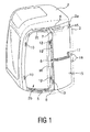
- a conventional sliding door device for heavy construction equipment includes a sliding door 3 sliding to move on an outer side wall 2a of a cab 2; a plurality of rails 4, 5, and 6 formed in upper, lower, and center parts of the outer side wall 2a; a plurality of rollers 7, 8, and 9 mounted on the door 3 to support the door 3 when the door 3 slides between a closed position where a doorway 2b is closed and an open position where the doorway 2b is open; a plurality of pairs of strikers 10, 11, 12, and 13, each of the pairs of strikers including a female striker 10 or 12 and a mail striker 11 or 13, one of the strikers of each pair being mounted on the door 3, and the other striker of the respective pair being mounted on an outer side wall 2c, so that at least one pair of strikers are engaged with each other when the door is in its closed position and at least one pair of strikers are engaged with each other when the door is in its fully opened position; wherein at least one of the
- An upper roller 7 includes a guide roller 7a that moves along an upper rail 4 when a door 3 is opened or closed
- a lower roller 8 includes a rolling roller 8a which is rotated in an X-axis direction (that means the front/rear direction of a cab) along the lower rail 5 to support the load of the door 3 when the door 3 is opened or closed
- a guide roller 8b which is rotated in a Y-axis direction (that means each side direction of the cab) to prevent the door 3 from seceding from the lower rail 5 when the door 3 is opened or closed (See FIG. 2 ).
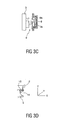
- a center roller 9 mounted on the door 3 includes a rolling roller 9a which is rotated in an X-axis direction to support the load of the door 3 when the door 3 is opened or closed, and a guide roller 9b which is rotated in a Y-axis direction to prevent the door 3 from seceding from the center rail 6 when the door 3 is opened or closed.
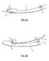
- the female and male strikers 10 and 11 are engaged with each other in a door closed position as illustrated in FIG. 3A
- the female and male strikers 12, 13, 14, and 15 are engaged with each other when the door 3 is moved in the X-axis direction and approaches the rear side of the door, as illustrated in FIGs. 3B and 3D .
- the sliding movement of the door forms a straight or curved trace, and the load and the structure of the door or the structure of the rails may greatly hinder the opening and closing of the door.
- continuous research and development are required.
- the conventional sliding door for heavy construction equipment has the problem that the door is not kept in an open position where the sliding door is fully opened or in a closed position where the sliding door is fully closed, and secedes from the open position or the closed position due to trouble of a sliding door locking device or a door holder for fixedly keeping the open position and the closed position of the door, trouble of an upper rail or a lower rail, vibration of the equipment, and the like.
- the locking state of the door is released in a fully open/closed position of the door, and the door is arbitrarily moved in front/rear direction of a cab due to the self-weight of the door even if a small vibration or impact occurs, causing the occurrence of damage of rails or rollers and safety accident.
- the conventional sliding door device has the problem that, in the case where the open/closed state of the door becomes unstable during working of the construction equipment, an operator in a cab should control the open/closed state of the door at any time to deteriorate the workability, and contact and interference may occur between a control lever of a working device and the body of the operator to cause the malfunction of the equipment and to reduce the manipulability.
- the present invention has been made to solve the above-mentioned problems occurring in the prior art while advantages achieved by the prior art are maintained intact.
- One object of the present invention is to provide a sliding door safety device for heavy construction equipment, which can sense a secession of a sliding door when the door secedes from an open position where the door is fully opened or a closed position where the door is fully closed.
- Another object of the present invention is to provide a sliding door safety device for heavy construction equipment, which can provide alarm notification to an operator, and control the driving of an operation lever in a cab and an actuator of a working device when the door secedes from an open position or a closed position of the door to improve the manipulability and working performance of the equipment.
- a sliding door safety device for heavy construction equipment which includes an outer side wall having a doorway formed thereon; an upper rail and a lower rail formed on an upper part and a lower part of the outer side wall, respectively; a sliding door sliding to move to a front or rear side of a cab by an upper roller and a lower roller engaged with the upper rail and the lower rail, respectively, to open or close the doorway; and first and second door position sensing switches mounted on one side of the outer side wall to sense a door position when the door is in its open position where the door is fully opened or in its closed position where the door is fully closed.
- the door position sensing switches may be limit switches.
- An upper roller support bracket may be installed on the inside of the sliding door so that the upper roller is engaged with the upper rail to be rotatable, and a switch driving member for driving the first door position sensing switch may be provided on the support bracket.
- a lower roller support bracket may be installed on the inside of the sliding door so that the lower roller is engaged with the lower rail to be rotatable, and a switch driving member for driving the second door position sensing switch may be provided on one side of the support bracket.
- the door position sensing switch may be connected to an electronic controller, and may generate a door secession signal when the sliding door secedes from the open position or the closed position.
- the sliding door safety device may further include an alarm which is installed in the cab and is controlled by the electronic controller to provide an alarm signal to an operator when the sliding door secedes from the open position or the closed position.
- either of the first and second door position sensing switches may generate a door secession signal.
- either of the first and second door position sensing switches may generate a door secession signal.
- the sliding door safety device may further include a center rail formed on the outer side wall of the cab, and a center roller formed on the sliding door to be engaged with the center rail.
- the sliding door safety device may further include an upper stopper in the open position, mounted on the outer side wall in the open position where the sliding door is fully open, the upper stopper being in contact with the upper roller to prevent the sliding door from shaking when the sliding door is fully open; and a lower stopper in the open position, mounted on the outer side wall in the open position where the sliding door is fully open, the lower stopper being in contact with the lower roller to prevent the sliding door from shaking when the sliding door is fully open; wherein the door position sensing switches are installed adjacent to the upper stopper and the lower stopper, respectively.
- the sliding door safety device may further include a center stopper in the open position, mounted on the outer side wall in the open position where the sliding door is fully open, the center stopper being in contact with the center roller to prevent the sliding door from shaking when the sliding door is fully open.
- the sliding door safety device may further include a door fixing holder that fixes the sliding door in the open position when the sliding door is fully opened.
- the sliding door safety device may further include a working device operation lever and a working device actuator member which are connected to the electronic controller; wherein, when the door secession signal is applied from the door position sensing switch, the electronic controller selectively controls the operation of the working device operation lever and the working device actuator member.
- the sliding door safety device may further include a switch driving member provided on one side of an inner panel of the sliding door, wherein, when the sliding door is in the open position or the closed position, either of the first and second door position sensing switches is driven by the switch driving member.
- X-axis direction means a front/rear direction of a cab that is provided in the rear of a working device such as a boom
- Y-axis direction means a left/right direction of the cab
- Z-axis direction means an upper/lower direction of the cab.
- FIG. 1 is a perspective view of a cab in the prior art
- FIG. 2 is a side view of a sliding door as shown in FIG. 1
- FIG. 3A is a section view along line S-S in FIG. 2 , showing the sliding door in a closed state
- FIG. 3B is a section view along line T-T in FIG. 2 , showing the sliding door in an open state
- FIG. 3C is a sectional view of a center rail and a center roller as shown in FIG. 1
- FIG. 3D is an enlarged view of a part indicated by a circle in FIG. 3B
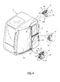
- FIG. 4 is a perspective view illustrating a sliding door safety device for heavy construction equipment according to an embodiment of the present invention
- FIG. 4 is a perspective view illustrating a sliding door safety device for heavy construction equipment according to an embodiment of the present invention
- FIG. 5 is a schematic view illustrating a flow of controlling a working device by a door secession signal of a door position sensing switch according to an embodiment of the present invention.
- FIG. 6 is a view explaining the operation state of a door position sensing switch in accordance with the movement of an upper roller as shown in FIG. 4
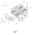
- FIG. 7 is a view illustrating the use state of a center stopper as shown in FIG. 4
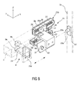
- FIG. 8 is a view explaining the operation state of a door position sensing switch in accordance with the movement of an upper roller as shown in FIG. 4
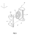
- FIG. 9 is a view illustrating the use state of a door fixing holder as shown in FIG. 4
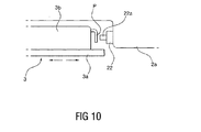
- FIG. 10 is a schematic view illustrating the operation state of a switch driving member installed on an inner panel of the door to operate a door position sensing switch according to another embodiment of the present invention.
- the sliding door safety device can be provided in a cab of heavy construction equipment having a sliding door to sense the open position and the closed position of the door.
- the sliding door safety device for heavy construction equipment includes an outer side wall 2a having a doorway 2b formed thereon; an upper rail 4 and a lower rail 5 formed on an upper part and a lower part of the outer side wall 2a, respectively; a sliding door 3 sliding to move to a front or rear side of a cab 2 by an upper roller 7 and a lower roller 8 engaged with the upper rail 4 and the lower rail 5, respectively, to open or close the doorway 2a; and first and second door position sensing switches 22 and 22' mounted on one side of the outer side wall 2a to sense a door position when the door 3 is in its open position where the door 3 is fully opened or in its closed position where the door 3 is fully closed.
- the door position sensing switches 22 and 22' are limit switches which generate electric signals when the sliding door 3 is in its open position where the door is fully opened or in its closed position where the door is fully closed.
- the upper roller 7 includes a guide roller 7a that is rotated in a Y-axis direction along the upper rail 4 when the sliding door 3 is opened or closed.
- the lower roller 8 includes a first lower roller (that means a rolling roller 8a of the lower roller 8) which is rotated in an X-axis direction along the lower rail 5 to support the load of the sliding door 3 when the sliding door 3 is opened or closed, and a second lower roller (that means a guide roller 8b of the lower roller 8) which is rotated in a Y-axis direction to prevent the sliding door 3 from seceding from the lower rail 5 when the sliding door 3 is opened or closed.
- an upper roller support bracket 24 is installed on the inside of the sliding door 3 so that the upper roller 7 is engaged with the upper rail 4 to be rotatable, and a switch driving member 24a is provided on one side of the support bracket 24.
- the switch driving member 24a becomes in contact with and secedes from a contact part 22a of the first door position sensing switch 22 so that the first door position sensing switch 22 performs the door position sensing function when the door 3 is in the open position and in the closed position, respectively.
- a lower roller support bracket 24' is installed on the inside of the sliding door 3 so that the lower roller 8 is engaged with the lower rail 5 to be rotatable, and a switch driving member 24a' is provided on one side of the lower roller support bracket 24'.
- the switch driving member 24a' becomes in contact with and secedes from a contact part 22a' of the second door position sensing switch 22' so that the second door position sensing switch 22' performs the door position sensing function when the door 3 is in the open position and in the closed position, respectively.
- switch driving members 24a and 24a' are formed in a body with the sides of the upper roller and lower roller support brackets 24 and 24' so that the switch driving members 24a and 24a' perform the operation of the door position sensing switches 22 and 22', respectively, when the sliding door 3 is in the open position and in the closed position.
- elastic members including springs may be further installed on the sides of the upper roller and lower roller support brackets 24 and 24', respectively, so that the respective switch driving members 24a and 24a' have elastic forces, and to do so is preferable in buffering impact that acts on the first and second door position sensing switches 22 and 22', the upper roller 7, and the lower roller, respectively, when the door 3 is in the open position and in the closed position.
- the first door position sensing switch 22 performs the door position sensing function in a manner that if the sliding door 3 is in the open position, the switch driving member 24a of the upper roller support bracket 24 becomes in contact with the contact part 22a of the first door position sensing switch 22 to support the contact part, while if the sliding door 3 moves along the upper rail 4 and secedes from the open position of the door, the first door position sensing switch 22 generates the door secession signal.
- the second door position sensing switch 22' performs the door position sensing function in a manner that if the sliding door 3 is in the closed position, the switch driving member 24a' of the lower roller support bracket 24' becomes in contact with the contact part 22a' of the second door position sensing switch 22' to support the contact part, while if the sliding door 3 moves along the lower rail 5 and secedes from the closed position of the door, the second door position sensing switch 22' generates the door secession signal.
- the switch driving member 24a or 24a' is provided on one side of an inner panel 3b of the sliding door 3, and either of the first door position sensing switch 22 and the second door position sensing switch 22' is operated to provide the door secession signal to the electronic controller 25 when the sliding door 3 is in the open position or in the closed position.
- the respective switch driving members 24a and 24a' are provided on one side of the inner panel 3b of the sliding door 3
- at least one of the switch driving members 24a and 24a' is provided with a projection part P which projects from the inner panel 3b and is in contact with the contact part 22a or 22a' of the first or second door position sensing switch 22 or 22'.
- the first and second door position sensing switches 22 and 22' are connected to an electronic controller 25, and the door position sensing switches 22 and 22' provide door secession signals to the electronic controller 25 when the sliding door secedes from the open position or the closed position.
- the electronic controller 25 is connected to an alarm 37 installed inside the cab 2.
- the electronic controller 25 is also connected to a monitor 36 installed inside the cab 2, a working device operation lever 38, and a working device actuator member 39 that is driven under the control of the working device operation lever 38.
- the electronic controller 25 When the door secession signal generated by the respective door position sensing switch 22 or 22' is inputted, the electronic controller 25 operates the monitor 36 and the alarm 37 for operator alarm, and controls an electric signal and a hydraulic signal for selecting the driving range of the working device operation lever 38 and the working device actuator member 39.
- the first and second door position sensing switches 22 and 22' perform the door position sensing function, and thus the electronic controller 25 can perform the electric operation of the working device operation lever 38 and the control of hydraulic driving rate of the working device actuator member 39.
- the first door position sensing switch 22 generates the door secession signal when the upper roller 7 secedes from the upper rail 4. Also, the second door position sensing switch 22' generates the door secession signal when the lower roller 8 secedes from the lower rail 5.
- the sliding door safety device further includes a door fixing holder 40 that fixes the sliding door in the open position when the sliding door is fully opened.
- the door fixing holder 40 includes a stopper bar 34 installed on one side of the outer side wall 20, and a holding plate 33 installed on the inside of the sliding door 3 to be engaged with the stopper bar 34.
- a locking piece 35 for fastening a fixing locking member (not illustrated) including a hook member or a locking striker is formed on one side of the stopper bar 34.
- the sliding door safety device further includes a center rail 6 formed on the outer side wall 2a of the cab 2, and a center roller 9 formed on the sliding door 3 to be engaged with the center rail 6.
- the center roller 9 includes a first center roller (which means a rolling roller 9a of the center roller 9) that is rotated in X-axis direction along the center rail 6 to support the load of the sliding door 3 when the sliding door 3 is opened or closed, and a second center roller (which means a guide roller 9b of the center roller 9) that is rotated in Y-axis direction to prevent the sliding door 3 from seceding from the center rail 6 when the sliding door 3 is opened or closed.
- the sliding door safety device further includes an upper stopper 21 in the open position, mounted on the outer side wall 2a in the open position where the sliding door 3 is fully open, the upper stopper 21 being in contact with the upper roller 7 to prevent the sliding door from shaking when the sliding door 3 is fully open; and a lower stopper 23 in the open position, mounted on the outer side wall 2a in the open position where the sliding door 3 is fully open, the lower stopper 23 being in contact with the lower roller 8 to prevent the sliding door 3 from shaking when the sliding door 3 is fully open; wherein the door position sensing switches 24 and 24' are installed adjacent to the upper stopper 21 and the lower stopper 23, respectively.
- the sliding door safety device further includes a center stopper 22 in the open position, mounted on the outer side wall 2a in the open position where the sliding door 3 is fully open, the center stopper being in contact with the center roller 9 to prevent the sliding door 3 from shaking when the sliding door 3 is fully open.
- the upper stopper 21 fixes a pad 20 by elastic restoring force of elastic members 26 and 27 elastically installed on a guide 25.
- the guide roller 7a is pressed in X-axis direction (i.e. the front/rear direction of the cab 2) as shown in the drawing by the structure of an inclined surface 20a of the pad 20 of which the position is fixed, and thus the sliding door 3 is prevented from shaking or moving in the X-axis direction.
- the guide roller 7a of the upper roller 7 is pressed in Y-axis direction (i.e. the side direction of the cab 2) as shown in the drawing by the contact support of the pad 20, and thus the sliding door 3 is prevented from shaking or moving in the Y-axis direction.
- the lower stopper 23 includes a first lower stopper 23a installed to press the first lower roller (i.e. the rolling roller 8a of the lower roller 8) in X-axis and Z-axis directions by the contact of the pad 20 to prevent the sliding door 3 from shaking in the X-axis (i.e. the side direction of the cab 2) and Z-axis (i.e. the upper/lower direction of the cab 2) directions when the sliding door 3 is fully opened or closed; and a second lower stopper 23b installed to press the second lower roller (i.e.
- the guide roller 8b of the lower roller 8) in X-axis and Y-axis directions by the contact of the pad 20 to prevent the sliding door 3 from shaking in the X-axis and Y-axis directions when the sliding door 3 is fully opened or closed.
- the center stopper 22 includes a first center stopper 22a installed to press the first center roller (i.e. the rolling roller 9a of the center roller 9) in X-axis and Z-axis directions by the contact of the pad 20 to prevent the sliding door 3 from shaking in the X-axis and Z-axis directions when the sliding door 3 is fully opened; and a second center stopper 22b installed to press the second center roller (i.e. the guide roller 9b of the center roller 9) in X-axis and Y-axis directions by the contact of the pad 20 to prevent the sliding door 3 from shaking in the X-axis and Y-axis directions when the sliding door 3 is fully opened.
- a first center stopper 22a installed to press the first center roller (i.e. the rolling roller 9a of the center roller 9) in X-axis and Z-axis directions by the contact of the pad 20 to prevent the sliding door 3 from shaking in the X-axis and Z-axis directions when the sliding door 3 is fully opened
- the upper stopper 21, the center stopper 22, and the lower stopper 23, as described above, may be installed to be positioned in inner end parts of the upper rail 4, the center rail 6, and the lower rail, respectively, in the open position where the sliding door 3 is fully opened.
- the upper stopper 21 or the lower stopper 23 may be modified to be positioned in the inner end part of the upper rail 4 or the lower rail 5 in the closed position where the sliding door 3 is fully closed and in the open position where the sliding door 3 is fully opened.
- the switch driving members 24a and 24a' formed on the upper roller and lower roller support brackets 24 and 24' are arranged adjacent to an upper pillar and a lower pillar of the outer side wall 2a having the doorway 2b formed thereon, respectively, when the sliding door 3 approaches the open position and the closed position thereof in the opening and closing processes of the sliding door 3, and finally become in selective contact with the first and second door position sensing switches 22 and 22', respectively, when the sliding door 3 is in the open position and in the closed position.
- the first or second door position sensing switch 22 or 22' quickly senses this.
- the sliding door 3 secedes from the open position formed on the outer side wall 2a of the doorway 2b, the contact between the switch driving member 24a of the support bracket 24 and the contact part 22a of the first door position sensing switch 22 is released, and the first door position sensing switch 22 provides the door secession signal (e.g. electric on/off signal of the limit switch) to the electronic controller 25.
- the door secession signal e.g. electric on/off signal of the limit switch
- the electronic controller 25 When the door secession signal generated by the first door position sensing switch 22 is received, the electronic controller 25 provides audible and visible alarm signals to the monitor 36 and the alarm 37, and simultaneously limits or stops the operation of the working device operation lever 38 and the working device actuator member 39 through preset hydraulic and electronic control logics.
- the electronic controller 25 provides the audible and visible alarm signals to the monitor 36 and the alarm 37, and simultaneously performs the operation of the working device operation lever 38 and the working device actuator member 39 through the preset hydraulic and electronic control logics in the same manner.
- the sliding door safety device for heavy construction equipment according to the present invention, if the sliding door is not kept in the open position where the sliding door is fully opened or in the closed position where the sliding door is fully closed and secedes from the open position or the closed position, the sliding door safety device senses this, provides an alarm notification to the operator, and stably controls the operation lever in the cab and the working device to improve the workability and manipulability. Also, the sliding door safety device can properly control the operation lever and the hydraulic supply performance of the working device depending on whether the door secedes from the open position or the closed position.
Landscapes
- Engineering & Computer Science (AREA)
- Mining & Mineral Resources (AREA)
- Civil Engineering (AREA)
- General Engineering & Computer Science (AREA)
- Structural Engineering (AREA)
- Mechanical Engineering (AREA)
- Power-Operated Mechanisms For Wings (AREA)
- Component Parts Of Construction Machinery (AREA)
Abstract
Description
- This application is based on and claims priority from Korean Patent Application No.
10-2008-0087777, filed on September 5, 2008 - The present invention relates to a sliding door safety device for heavy construction equipment, and more particularly, to a sliding door safety device for heavy construction equipment, which can quickly provide alarm notification to an operator and properly control the lever operation and the hydraulic operation of a working device when a sliding door mounted on a cab is not fixedly kept in an open position where the sliding door is fully opened or in a closed position where the sliding door is fully closed, and secedes from the open position or the closed position due to trouble of a door locking device, rails and a roller device, vibration of the equipment, and the like.
- Generally, in heavy construction equipment such as an excavator, a cab door, which is opened or closed by a hinge structure, has the problem that it may be interfered with an external object, such as a surrounding building or tree, when the equipment performs a swing operation in a downtown area or in a confined place. In order to solve this problem, a sliding door device provided with a sliding door and guide rails on a cab has been known. The sliding door device enables the door to be opened or closed by guiding the sliding movement of the door on the guide rails when the door is opened or closed.
- As illustrated in
FIGs. 1 to 3D , a conventional sliding door device for heavy construction equipment includes a slidingdoor 3 sliding to move on anouter side wall 2a of acab 2; a plurality ofrails outer side wall 2a; a plurality ofrollers door 3 to support thedoor 3 when thedoor 3 slides between a closed position where adoorway 2b is closed and an open position where thedoorway 2b is open; a plurality of pairs ofstrikers female striker mail striker door 3, and the other striker of the respective pair being mounted on anouter side wall 2c, so that at least one pair of strikers are engaged with each other when the door is in its closed position and at least one pair of strikers are engaged with each other when the door is in its fully opened position; wherein at least one of the plurality of pairs ofstrikers door 3 when thedoor 3 is fully opened, and at least one other pair of the plurality of pairs of strikers is mounted for engaging each other at a rear edge portion of thedoor 3 when thedoor 3 is fully opened. - The conventional sliding door device as described above is disclosed in
U.S. Patent No. 5,577,795 . Anupper roller 7 includes aguide roller 7a that moves along anupper rail 4 when adoor 3 is opened or closed, and alower roller 8 includes arolling roller 8a which is rotated in an X-axis direction (that means the front/rear direction of a cab) along the lower rail 5 to support the load of thedoor 3 when thedoor 3 is opened or closed, and aguide roller 8b which is rotated in a Y-axis direction (that means each side direction of the cab) to prevent thedoor 3 from seceding from the lower rail 5 when thedoor 3 is opened or closed (SeeFIG. 2 ). - Also, referring to
FIG. 3 , a center roller 9 mounted on thedoor 3 includes arolling roller 9a which is rotated in an X-axis direction to support the load of thedoor 3 when thedoor 3 is opened or closed, and aguide roller 9b which is rotated in a Y-axis direction to prevent thedoor 3 from seceding from thecenter rail 6 when thedoor 3 is opened or closed. - As described above, in the conventional sliding door device, the female and
male strikers FIG. 3A , while in a door open position, the female andmale strikers door 3 is moved in the X-axis direction and approaches the rear side of the door, as illustrated inFIGs. 3B and3D . - According to the conventional sliding door device as described above, the sliding movement of the door forms a straight or curved trace, and the load and the structure of the door or the structure of the rails may greatly hinder the opening and closing of the door. In order to improve this, continuous research and development are required.
- The conventional sliding door for heavy construction equipment has the problem that the door is not kept in an open position where the sliding door is fully opened or in a closed position where the sliding door is fully closed, and secedes from the open position or the closed position due to trouble of a sliding door locking device or a door holder for fixedly keeping the open position and the closed position of the door, trouble of an upper rail or a lower rail, vibration of the equipment, and the like.
- That is, according to the conventional sliding door device, due to long-term use of the door and so on, the locking state of the door is released in a fully open/closed position of the door, and the door is arbitrarily moved in front/rear direction of a cab due to the self-weight of the door even if a small vibration or impact occurs, causing the occurrence of damage of rails or rollers and safety accident.
- Also, the conventional sliding door device has the problem that, in the case where the open/closed state of the door becomes unstable during working of the construction equipment, an operator in a cab should control the open/closed state of the door at any time to deteriorate the workability, and contact and interference may occur between a control lever of a working device and the body of the operator to cause the malfunction of the equipment and to reduce the manipulability.
- Accordingly, the present invention has been made to solve the above-mentioned problems occurring in the prior art while advantages achieved by the prior art are maintained intact.
- One object of the present invention is to provide a sliding door safety device for heavy construction equipment, which can sense a secession of a sliding door when the door secedes from an open position where the door is fully opened or a closed position where the door is fully closed.
- Another object of the present invention is to provide a sliding door safety device for heavy construction equipment, which can provide alarm notification to an operator, and control the driving of an operation lever in a cab and an actuator of a working device when the door secedes from an open position or a closed position of the door to improve the manipulability and working performance of the equipment.
- In order to accomplish these objects, there is provided a sliding door safety device for heavy construction equipment, according to an embodiment of the present invention, which includes an outer side wall having a doorway formed thereon; an upper rail and a lower rail formed on an upper part and a lower part of the outer side wall, respectively; a sliding door sliding to move to a front or rear side of a cab by an upper roller and a lower roller engaged with the upper rail and the lower rail, respectively, to open or close the doorway; and first and second door position sensing switches mounted on one side of the outer side wall to sense a door position when the door is in its open position where the door is fully opened or in its closed position where the door is fully closed.
- The door position sensing switches may be limit switches.
- An upper roller support bracket may be installed on the inside of the sliding door so that the upper roller is engaged with the upper rail to be rotatable, and a switch driving member for driving the first door position sensing switch may be provided on the support bracket.
- A lower roller support bracket may be installed on the inside of the sliding door so that the lower roller is engaged with the lower rail to be rotatable, and a switch driving member for driving the second door position sensing switch may be provided on one side of the support bracket.
- The door position sensing switch may be connected to an electronic controller, and may generate a door secession signal when the sliding door secedes from the open position or the closed position.
- The sliding door safety device according to an embodiment of the present invention may further include an alarm which is installed in the cab and is controlled by the electronic controller to provide an alarm signal to an operator when the sliding door secedes from the open position or the closed position.
- If the upper roller moves the upper rail and the sliding door secedes from the fully open position or the fully closed position of the door, either of the first and second door position sensing switches may generate a door secession signal.
- If the lower roller moves the lower rail and the sliding door secedes from the fully open position or the fully closed position of the door, either of the first and second door position sensing switches may generate a door secession signal.
- The sliding door safety device according to an embodiment of the present invention may further include a center rail formed on the outer side wall of the cab, and a center roller formed on the sliding door to be engaged with the center rail.
- The sliding door safety device according to an embodiment of the present invention may further include an upper stopper in the open position, mounted on the outer side wall in the open position where the sliding door is fully open, the upper stopper being in contact with the upper roller to prevent the sliding door from shaking when the sliding door is fully open; and a lower stopper in the open position, mounted on the outer side wall in the open position where the sliding door is fully open, the lower stopper being in contact with the lower roller to prevent the sliding door from shaking when the sliding door is fully open; wherein the door position sensing switches are installed adjacent to the upper stopper and the lower stopper, respectively.
- The sliding door safety device according to an embodiment of the present invention may further include a center stopper in the open position, mounted on the outer side wall in the open position where the sliding door is fully open, the center stopper being in contact with the center roller to prevent the sliding door from shaking when the sliding door is fully open.
- The sliding door safety device according to an embodiment of the present invention may further include a door fixing holder that fixes the sliding door in the open position when the sliding door is fully opened.
- The sliding door safety device according to an embodiment of the present invention may further include a working device operation lever and a working device actuator member which are connected to the electronic controller; wherein, when the door secession signal is applied from the door position sensing switch, the electronic controller selectively controls the operation of the working device operation lever and the working device actuator member.
- The sliding door safety device according to an embodiment of the present invention may further include a switch driving member provided on one side of an inner panel of the sliding door, wherein, when the sliding door is in the open position or the closed position, either of the first and second door position sensing switches is driven by the switch driving member.
- The above and other objects, features and advantages of the present invention will be more apparent from the following detailed description taken in conjunction with the accompanying drawings, in which:
-
FIG. 1 is a perspective view of a cab in the prior art; -
FIG. 2 is a side view of a sliding door as shown inFIG. 1 ; -
FIG. 3A is a section view along line S-S inFIG. 2 , showing the sliding door in a closed state; -
FIG. 3B is a section view along line T-T inFIG. 2 , showing the sliding door in an open state; -
FIG. 3C is a sectional view of a center rail and a center roller as shown inFIG. 1 ; -
FIG. 3D is an enlarged view of a part indicated by a circle inFIG. 3B ; -
FIG. 4 is a perspective view illustrating a sliding door safety device for heavy construction equipment according to an embodiment of the present invention; -
FIG. 5 is a schematic view illustrating a flow of controlling a working device by a door secession signal of a door position sensing switch according to an embodiment of the present invention; -
FIG. 6 is a view explaining the operation state of a door position sensing switch in accordance with the movement of an upper roller as shown inFIG. 4 ; -
FIG. 7 is a view illustrating the use state of a center stopper as shown inFIG. 4 ; -
FIG. 8 is a view explaining the operation state of a door position sensing switch in accordance with the movement of an upper roller as shown inFIG. 4 ; -
FIG. 9 is a view illustrating the use state of a door fixing holder as shown inFIG. 4 ; and -
FIG. 10 is a schematic view illustrating the operation state of a switch driving member installed on an inner panel of the door to operate a door position sensing switch according to another embodiment of the present invention. - Hereinafter, a preferred embodiment of the present invention will be described with reference to the accompanying drawings. The matters defined in the description, such as the detailed construction and elements, are nothing but specific details provided to assist those of ordinary skill in the art in a comprehensive understanding of the invention, and thus the present invention is not limited thereto.
- In the description of the present invention, X-axis direction means a front/rear direction of a cab that is provided in the rear of a working device such as a boom, Y-axis direction means a left/right direction of the cab, and Z-axis direction means an upper/lower direction of the cab.
-
FIG. 1 is a perspective view of a cab in the prior art, andFIG. 2 is a side view of a sliding door as shown inFIG. 1 .FIG. 3A is a section view along line S-S inFIG. 2 , showing the sliding door in a closed state,FIG. 3B is a section view along line T-T inFIG. 2 , showing the sliding door in an open state,FIG. 3C is a sectional view of a center rail and a center roller as shown inFIG. 1 , andFIG. 3D is an enlarged view of a part indicated by a circle inFIG. 3B .FIG. 4 is a perspective view illustrating a sliding door safety device for heavy construction equipment according to an embodiment of the present invention, andFIG. 5 is a schematic view illustrating a flow of controlling a working device by a door secession signal of a door position sensing switch according to an embodiment of the present invention.FIG. 6 is a view explaining the operation state of a door position sensing switch in accordance with the movement of an upper roller as shown inFIG. 4 ,FIG. 7 is a view illustrating the use state of a center stopper as shown inFIG. 4 ,FIG. 8 is a view explaining the operation state of a door position sensing switch in accordance with the movement of an upper roller as shown inFIG. 4 ,FIG. 9 is a view illustrating the use state of a door fixing holder as shown inFIG. 4 , andFIG. 10 is a schematic view illustrating the operation state of a switch driving member installed on an inner panel of the door to operate a door position sensing switch according to another embodiment of the present invention. - The sliding door safety device according to an embodiment of the present invention can be provided in a cab of heavy construction equipment having a sliding door to sense the open position and the closed position of the door.
- The sliding door safety device for heavy construction equipment according to an embodiment of the present invention includes an
outer side wall 2a having adoorway 2b formed thereon; anupper rail 4 and a lower rail 5 formed on an upper part and a lower part of theouter side wall 2a, respectively; a slidingdoor 3 sliding to move to a front or rear side of acab 2 by anupper roller 7 and alower roller 8 engaged with theupper rail 4 and the lower rail 5, respectively, to open or close thedoorway 2a; and first and second door position sensing switches 22 and 22' mounted on one side of theouter side wall 2a to sense a door position when thedoor 3 is in its open position where thedoor 3 is fully opened or in its closed position where thedoor 3 is fully closed. - Preferably, the door position sensing switches 22 and 22' are limit switches which generate electric signals when the sliding
door 3 is in its open position where the door is fully opened or in its closed position where the door is fully closed. - Referring to
FIG. 6 , theupper roller 7 includes aguide roller 7a that is rotated in a Y-axis direction along theupper rail 4 when the slidingdoor 3 is opened or closed. Referring toFIG. 8 , thelower roller 8 includes a first lower roller (that means a rollingroller 8a of the lower roller 8) which is rotated in an X-axis direction along the lower rail 5 to support the load of the slidingdoor 3 when the slidingdoor 3 is opened or closed, and a second lower roller (that means aguide roller 8b of the lower roller 8) which is rotated in a Y-axis direction to prevent the slidingdoor 3 from seceding from the lower rail 5 when the slidingdoor 3 is opened or closed. - In the present invention, an upper
roller support bracket 24 is installed on the inside of the slidingdoor 3 so that theupper roller 7 is engaged with theupper rail 4 to be rotatable, and aswitch driving member 24a is provided on one side of thesupport bracket 24. Theswitch driving member 24a becomes in contact with and secedes from acontact part 22a of the first doorposition sensing switch 22 so that the first doorposition sensing switch 22 performs the door position sensing function when thedoor 3 is in the open position and in the closed position, respectively. - Also, a lower roller support bracket 24' is installed on the inside of the sliding
door 3 so that thelower roller 8 is engaged with the lower rail 5 to be rotatable, and aswitch driving member 24a' is provided on one side of the lower roller support bracket 24'. Theswitch driving member 24a' becomes in contact with and secedes from acontact part 22a' of the second door position sensing switch 22' so that the second door position sensing switch 22' performs the door position sensing function when thedoor 3 is in the open position and in the closed position, respectively. - It is preferable to form the respective
switch driving members roller support brackets 24 and 24' so that theswitch driving members door 3 is in the open position and in the closed position. - In the present invention, elastic members including springs may be further installed on the sides of the upper roller and lower
roller support brackets 24 and 24', respectively, so that the respectiveswitch driving members upper roller 7, and the lower roller, respectively, when thedoor 3 is in the open position and in the closed position. - On the other hand, if the
upper roller 7 moves along theupper rail 4 and the slidingdoor 3 secedes from the fully open position or the fully closed position, either of the first and second door position sensing switches 22 and 22' generates a door secession signal, while if thelower roller 8 moves along the lower rail 5 and the slidingdoor 3 secedes from the fully open position or the fully closed position, either of the first and second door position sensing switches 22 and 22' generates a door secession signal. - Preferably, the first door
position sensing switch 22 performs the door position sensing function in a manner that if the slidingdoor 3 is in the open position, theswitch driving member 24a of the upperroller support bracket 24 becomes in contact with thecontact part 22a of the first doorposition sensing switch 22 to support the contact part, while if the slidingdoor 3 moves along theupper rail 4 and secedes from the open position of the door, the first doorposition sensing switch 22 generates the door secession signal. - Also, the second door position sensing switch 22' performs the door position sensing function in a manner that if the sliding
door 3 is in the closed position, theswitch driving member 24a' of the lower roller support bracket 24' becomes in contact with thecontact part 22a' of the second door position sensing switch 22' to support the contact part, while if the slidingdoor 3 moves along the lower rail 5 and secedes from the closed position of the door, the second door position sensing switch 22' generates the door secession signal. - In another embodiment of the present invention, as illustrated in
FIG. 10 , theswitch driving member inner panel 3b of the slidingdoor 3, and either of the first doorposition sensing switch 22 and the second door position sensing switch 22' is operated to provide the door secession signal to theelectronic controller 25 when the slidingdoor 3 is in the open position or in the closed position. In the case where the respectiveswitch driving members inner panel 3b of the slidingdoor 3, at least one of theswitch driving members inner panel 3b and is in contact with thecontact part position sensing switch 22 or 22'. - On the other hand, referring to
FIG. 5 , the first and second door position sensing switches 22 and 22' are connected to anelectronic controller 25, and the door position sensing switches 22 and 22' provide door secession signals to theelectronic controller 25 when the sliding door secedes from the open position or the closed position. - The
electronic controller 25 is connected to analarm 37 installed inside thecab 2. Theelectronic controller 25 is also connected to amonitor 36 installed inside thecab 2, a workingdevice operation lever 38, and a workingdevice actuator member 39 that is driven under the control of the workingdevice operation lever 38. - When the door secession signal generated by the respective door
position sensing switch 22 or 22' is inputted, theelectronic controller 25 operates themonitor 36 and thealarm 37 for operator alarm, and controls an electric signal and a hydraulic signal for selecting the driving range of the workingdevice operation lever 38 and the workingdevice actuator member 39. - That is, when the sliding
door 3 secedes from the open position or the closed position, the first and second door position sensing switches 22 and 22' perform the door position sensing function, and thus theelectronic controller 25 can perform the electric operation of the workingdevice operation lever 38 and the control of hydraulic driving rate of the workingdevice actuator member 39. - For example, in one embodiment of the present invention, the first door
position sensing switch 22 generates the door secession signal when theupper roller 7 secedes from theupper rail 4. Also, the second door position sensing switch 22' generates the door secession signal when thelower roller 8 secedes from the lower rail 5. - On the other hand, the sliding door safety device according to an embodiment of the present invention further includes a
door fixing holder 40 that fixes the sliding door in the open position when the sliding door is fully opened. Thedoor fixing holder 40 includes astopper bar 34 installed on one side of theouter side wall 20, and a holdingplate 33 installed on the inside of the slidingdoor 3 to be engaged with thestopper bar 34. - On one side of the
stopper bar 34, a lockingpiece 35 for fastening a fixing locking member (not illustrated) including a hook member or a locking striker is formed. - Also, the sliding door safety device according to an embodiment of the present invention further includes a
center rail 6 formed on theouter side wall 2a of thecab 2, and a center roller 9 formed on the slidingdoor 3 to be engaged with thecenter rail 6. The center roller 9 includes a first center roller (which means a rollingroller 9a of the center roller 9) that is rotated in X-axis direction along thecenter rail 6 to support the load of the slidingdoor 3 when the slidingdoor 3 is opened or closed, and a second center roller (which means aguide roller 9b of the center roller 9) that is rotated in Y-axis direction to prevent the slidingdoor 3 from seceding from thecenter rail 6 when the slidingdoor 3 is opened or closed. - The sliding door safety device according to an embodiment of the present invention further includes an
upper stopper 21 in the open position, mounted on theouter side wall 2a in the open position where the slidingdoor 3 is fully open, theupper stopper 21 being in contact with theupper roller 7 to prevent the sliding door from shaking when the slidingdoor 3 is fully open; and alower stopper 23 in the open position, mounted on theouter side wall 2a in the open position where the slidingdoor 3 is fully open, thelower stopper 23 being in contact with thelower roller 8 to prevent the slidingdoor 3 from shaking when the slidingdoor 3 is fully open; wherein the door position sensing switches 24 and 24' are installed adjacent to theupper stopper 21 and thelower stopper 23, respectively. - The sliding door safety device according to an embodiment of the present invention further includes a
center stopper 22 in the open position, mounted on theouter side wall 2a in the open position where the slidingdoor 3 is fully open, the center stopper being in contact with the center roller 9 to prevent the slidingdoor 3 from shaking when the slidingdoor 3 is fully open. - In one embodiment of the present invention, the
upper stopper 21 fixes apad 20 by elastic restoring force ofelastic members guide 25. Theguide roller 7a is pressed in X-axis direction (i.e. the front/rear direction of the cab 2) as shown in the drawing by the structure of aninclined surface 20a of thepad 20 of which the position is fixed, and thus the slidingdoor 3 is prevented from shaking or moving in the X-axis direction. Also, theguide roller 7a of theupper roller 7 is pressed in Y-axis direction (i.e. the side direction of the cab 2) as shown in the drawing by the contact support of thepad 20, and thus the slidingdoor 3 is prevented from shaking or moving in the Y-axis direction. - Also, the
lower stopper 23 includes a firstlower stopper 23a installed to press the first lower roller (i.e. the rollingroller 8a of the lower roller 8) in X-axis and Z-axis directions by the contact of thepad 20 to prevent the slidingdoor 3 from shaking in the X-axis (i.e. the side direction of the cab 2) and Z-axis (i.e. the upper/lower direction of the cab 2) directions when the slidingdoor 3 is fully opened or closed; and a secondlower stopper 23b installed to press the second lower roller (i.e. theguide roller 8b of the lower roller 8) in X-axis and Y-axis directions by the contact of thepad 20 to prevent the slidingdoor 3 from shaking in the X-axis and Y-axis directions when the slidingdoor 3 is fully opened or closed. - Also, the
center stopper 22 includes afirst center stopper 22a installed to press the first center roller (i.e. the rollingroller 9a of the center roller 9) in X-axis and Z-axis directions by the contact of thepad 20 to prevent the slidingdoor 3 from shaking in the X-axis and Z-axis directions when the slidingdoor 3 is fully opened; and a second center stopper 22b installed to press the second center roller (i.e. theguide roller 9b of the center roller 9) in X-axis and Y-axis directions by the contact of thepad 20 to prevent the slidingdoor 3 from shaking in the X-axis and Y-axis directions when the slidingdoor 3 is fully opened. - In modified embodiments of the present invention, the
upper stopper 21, thecenter stopper 22, and thelower stopper 23, as described above, may be installed to be positioned in inner end parts of theupper rail 4, thecenter rail 6, and the lower rail, respectively, in the open position where the slidingdoor 3 is fully opened. Also, according to circumstances, theupper stopper 21 or thelower stopper 23 may be modified to be positioned in the inner end part of theupper rail 4 or the lower rail 5 in the closed position where the slidingdoor 3 is fully closed and in the open position where the slidingdoor 3 is fully opened. - In the sliding door safety device according to the present invention, the
switch driving members roller support brackets 24 and 24' are arranged adjacent to an upper pillar and a lower pillar of theouter side wall 2a having thedoorway 2b formed thereon, respectively, when the slidingdoor 3 approaches the open position and the closed position thereof in the opening and closing processes of the slidingdoor 3, and finally become in selective contact with the first and second door position sensing switches 22 and 22', respectively, when the slidingdoor 3 is in the open position and in the closed position. - However, if the sliding
door 3 is not normally kept in the open position or the closed position of the door and secedes from the open position or the closed position due to the trouble of the typical sliding door locking device, thedoor holder 40, theupper rail 4, or the lower rail 5, and the vibration of the equipment, the first or second doorposition sensing switch 22 or 22' according to the present invention quickly senses this. - For example, if the sliding
door 3 secedes from the open position formed on theouter side wall 2a of thedoorway 2b, the contact between theswitch driving member 24a of thesupport bracket 24 and thecontact part 22a of the first doorposition sensing switch 22 is released, and the first doorposition sensing switch 22 provides the door secession signal (e.g. electric on/off signal of the limit switch) to theelectronic controller 25. - When the door secession signal generated by the first door
position sensing switch 22 is received, theelectronic controller 25 provides audible and visible alarm signals to themonitor 36 and thealarm 37, and simultaneously limits or stops the operation of the workingdevice operation lever 38 and the workingdevice actuator member 39 through preset hydraulic and electronic control logics. - By contrast, if the sliding
door 3 secedes from the closed position formed on theouter side wall 2a of thedoorway 2b, the contact between theswitch driving member 24a' of the lower roller support bracket 24' and thecontact part 22a' of the second door position sensing switch 22' is released, and the second door position sensing switch 22' provides the door secession signal to theelectronic controller 25. Thereafter, theelectronic controller 25 provides the audible and visible alarm signals to themonitor 36 and thealarm 37, and simultaneously performs the operation of the workingdevice operation lever 38 and the workingdevice actuator member 39 through the preset hydraulic and electronic control logics in the same manner. - As described above, according to the sliding door safety device for heavy construction equipment according to the present invention, if the sliding door is not kept in the open position where the sliding door is fully opened or in the closed position where the sliding door is fully closed and secedes from the open position or the closed position, the sliding door safety device senses this, provides an alarm notification to the operator, and stably controls the operation lever in the cab and the working device to improve the workability and manipulability. Also, the sliding door safety device can properly control the operation lever and the hydraulic supply performance of the working device depending on whether the door secedes from the open position or the closed position.
- Although preferred embodiments of the present invention have been described for illustrative purposes, those skilled in the art will appreciate that various modifications, additions and substitutions are possible, without departing from the scope and spirit of the invention as disclosed in the accompanying claims.
Claims (14)
- A sliding door safety device for heavy construction equipment, comprising:an outer side wall having a doorway formed thereon;an upper rail and a lower rail formed on an upper part and a lower part of the outer side wall, respectively;a sliding door sliding to move to a front or rear side of a cab by an upper roller and a lower roller engaged with the upper rail and the lower rail, respectively, to open or close the doorway; andfirst and second door position sensing switches mounted on one side of the outer side wall to sense a door position when the door is in its open position where the door is fully opened or in its closed position where the door is fully closed.
- The sliding door safety device of claim 1, wherein the door position sensing switches are limit switches.
- The sliding door safety device of claim 1, wherein an upper roller support bracket is installed on the inside of the sliding door so that the upper roller is engaged with the upper rail to be rotatable, and a switch driving member for driving the first door position sensing switch is provided on the support bracket.
- The sliding door safety device of claim 1, wherein a lower roller support bracket is installed on the inside of the sliding door so that the lower roller is engaged with the lower rail to be rotatable, and a switch driving member for driving the second door position sensing switch is provided on one side of the support bracket.
- The sliding door safety device of claim 1 or 2, wherein the door position sensing switch is connected to an electronic controller, and generates a door secession signal when the sliding door secedes from the open position or the closed position.
- The sliding door safety device of claim 1, further comprising an alarm which is installed in the cab and is controlled by an electronic controller to provide an alarm signal to an operator when the sliding door secedes from the open position or the closed position.
- The sliding door safety device of claim 1 or 3, wherein if the upper roller moves the upper rail and the sliding door secedes from the fully open position or the fully closed position of the door, either of the first and second door position sensing switches generates a door secession signal.
- The sliding door safety device of claim 1 or 4, wherein if the lower roller moves the lower rail and the sliding door secedes from the fully open position or the fully closed position of the door, either of the first and second door position sensing switches generates a door secession signal.
- The sliding door safety device of claim 1, further comprising a center rail formed on the outer side wall of the cab, and a center roller formed on the sliding door to be engaged with the center rail.
- The sliding door safety device of claim 1, further comprising:an upper stopper in the open position, mounted on the outer side wall in the open position where the sliding door is fully open, the upper stopper being in contact with the upper roller to prevent the sliding door from shaking when the sliding door is fully open; anda lower stopper in the open position, mounted on the outer side wall in the open position where the sliding door is fully open, the lower stopper being in contact with the lower roller to prevent the sliding door from shaking when the sliding door is fully open;wherein the door position sensing switches are installed adjacent to the upper stopper and the lower stopper, respectively.
- The sliding door safety device of claim 9 or 10, further comprising a center stopper in the open position, mounted on the outer side wall in the open position where the sliding door is fully open, the center stopper being in contact with the center roller to prevent the sliding door from shaking when the sliding door is fully open.
- The sliding door safety device of claim 9 or 10, further comprising a door fixing holder that fixes the sliding door in the open position when the sliding door is fully opened.
- The sliding door safety device of claim 1 or 9, further comprising a switch driving member provided on one side of an inner panel of the sliding door;
wherein, when the sliding door is in the open position or the closed position, either of the first and second door position sensing switches is driven by the switch driving member. - The sliding door safety device of claim 5, further comprising a working device operation lever and a working device actuator member which are connected to the electronic controller;
wherein, when the door secession signal is applied from the door position sensing switch, the electronic controller selectively controls the operation of the working device operation lever and the working device actuator member.
Applications Claiming Priority (1)
| Application Number | Priority Date | Filing Date | Title |
|---|---|---|---|
| KR1020080087777A KR101100259B1 (en) | 2008-09-05 | 2008-09-05 | Sliding door safety device for heavy construction equipment |
Publications (3)
| Publication Number | Publication Date |
|---|---|
| EP2161150A2 true EP2161150A2 (en) | 2010-03-10 |
| EP2161150A3 EP2161150A3 (en) | 2013-03-13 |
| EP2161150B1 EP2161150B1 (en) | 2015-04-15 |
Family
ID=41394966
Family Applications (1)
| Application Number | Title | Priority Date | Filing Date |
|---|---|---|---|
| EP09011279.8A Not-in-force EP2161150B1 (en) | 2008-09-05 | 2009-09-02 | Sliding door safety device for heavy construction equipment |
Country Status (5)
| Country | Link |
|---|---|
| US (1) | US8454081B2 (en) |
| EP (1) | EP2161150B1 (en) |
| JP (1) | JP2010058785A (en) |
| KR (1) | KR101100259B1 (en) |
| CN (1) | CN101666108B (en) |
Cited By (2)
| Publication number | Priority date | Publication date | Assignee | Title |
|---|---|---|---|---|
| CN102392572A (en) * | 2011-07-15 | 2012-03-28 | 上海三一科技有限公司 | Movable door sliding and locking mechanism for crane cab and crane having the same |
| US9997266B2 (en) | 2015-12-28 | 2018-06-12 | Nuctech Company Limited | Protective device and laser raman safety inspection apparatus comprising the same |
Families Citing this family (18)
| Publication number | Priority date | Publication date | Assignee | Title |
|---|---|---|---|---|
| CN102644427A (en) * | 2011-02-22 | 2012-08-22 | 王英杰 | Cross sliding door body control structure |
| EP2803560B1 (en) * | 2012-01-12 | 2016-06-29 | Nissan Motor Company, Limited | Structure for side face of vehicle body |
| CN103469845A (en) * | 2013-09-02 | 2013-12-25 | 三一汽车制造有限公司 | Engineering machine and driving cab thereof |
| JP6202319B2 (en) * | 2013-10-29 | 2017-09-27 | アイシン精機株式会社 | Control device and control method for vehicle opening / closing body |
| JP7032168B2 (en) | 2018-02-14 | 2022-03-08 | 株式会社小松製作所 | Work vehicle and system including work vehicle |
| CN109577787B (en) * | 2018-12-29 | 2024-05-07 | 江苏三乔智能科技有限公司 | Lifting window frame special for caravan |
| US11142048B2 (en) * | 2019-03-08 | 2021-10-12 | Deere & Company | Operator cab with actuated front door |
| US11774990B2 (en) | 2019-12-30 | 2023-10-03 | Marathon Petroleum Company Lp | Methods and systems for inline mixing of hydrocarbon liquids based on density or gravity |
| US11607654B2 (en) | 2019-12-30 | 2023-03-21 | Marathon Petroleum Company Lp | Methods and systems for in-line mixing of hydrocarbon liquids |
| CA3104319C (en) | 2019-12-30 | 2023-01-24 | Marathon Petroleum Company Lp | Methods and systems for spillback control of in-line mixing of hydrocarbon liquids |
| USD980767S1 (en) * | 2020-04-09 | 2023-03-14 | LCI Italy s.r.l. | Hatch for a vehicle |
| USD987509S1 (en) * | 2020-04-09 | 2023-05-30 | LCI Italy s.r.l. | Hatch for a vehicle |
| USD987510S1 (en) * | 2020-09-30 | 2023-05-30 | LCI Italy s.r.l. | Hatch for a vehicle |
| US11578836B2 (en) | 2021-03-16 | 2023-02-14 | Marathon Petroleum Company Lp | Scalable greenhouse gas capture systems and methods |
| FR3124450B1 (en) * | 2021-06-25 | 2023-05-12 | Continental Automotive Gmbh | METHOD FOR DETECTING OPENING OPENINGS OF A MOTOR VEHICLE AND ASSOCIATED DETECTION DEVICE |
| US11447877B1 (en) | 2021-08-26 | 2022-09-20 | Marathon Petroleum Company Lp | Assemblies and methods for monitoring cathodic protection of structures |
| US20230278404A1 (en) * | 2022-03-07 | 2023-09-07 | The Shyft Group, Inc. | Delivery Vehicle |
| US11686070B1 (en) * | 2022-05-04 | 2023-06-27 | Marathon Petroleum Company Lp | Systems, methods, and controllers to enhance heavy equipment warning |
Citations (1)
| Publication number | Priority date | Publication date | Assignee | Title |
|---|---|---|---|---|
| US5577795A (en) | 1992-07-21 | 1996-11-26 | Kabushiki Kaisha Komatsu Seisakusho | Operator cab door of construction machine |
Family Cites Families (16)
| Publication number | Priority date | Publication date | Assignee | Title |
|---|---|---|---|---|
| GB2164090B (en) * | 1984-07-26 | 1987-10-14 | Ohi Seisakusho Co Ltd | Automatic sliding door system for vehicles |
| JPH0425901Y2 (en) * | 1986-05-08 | 1992-06-22 | ||
| JP3442825B2 (en) * | 1993-09-08 | 2003-09-02 | 石川島建機株式会社 | Cabin door equipment for construction machinery |
| GB2295695B (en) * | 1994-12-01 | 1999-01-20 | Lucas Ind Plc | Cruise control system for a road vehicle |
| KR100226674B1 (en) * | 1996-12-27 | 1999-10-15 | 정몽규 | Apparatus for preventing closing of a sliding door for a vehicle |
| JP3656788B2 (en) * | 1997-03-31 | 2005-06-08 | 株式会社大井製作所 | Open / close control device for vehicle sliding door |
| KR100232773B1 (en) * | 1997-09-30 | 1999-12-01 | 정몽규 | Guider roller structure of sliding door for a bus |
| AT411283B (en) * | 2000-03-16 | 2003-11-25 | Knorr Bremse Gmbh | CONTROLLING THE MOVEMENT OF A SLIDING OR Pivoting sliding door in your closing area |
| ITMI20021112A1 (en) * | 2002-05-23 | 2003-11-24 | Faac Spa | HANDLING AND LOCKING DEVICE FOR MOTORIZED SLIDING DOORS |
| JP2005171610A (en) * | 2003-12-10 | 2005-06-30 | Kanto Auto Works Ltd | Sliding door opening and closing state detection switch |
| CZ2004922A3 (en) * | 2004-09-02 | 2006-04-12 | Vúkv A. S. | Door with a drive mediated by a linear electric motor of mass transportation conveyances, particularly rail vehicles |
| KR100753985B1 (en) * | 2006-03-13 | 2007-08-31 | 볼보 컨스트럭션 이키프먼트 홀딩 스웨덴 에이비 | Cab of heavy construction equipment |
| KR100734441B1 (en) * | 2006-03-30 | 2007-07-03 | 볼보 컨스트럭션 이키프먼트 홀딩 스웨덴 에이비 | Cab door of construction heavy equipment |
| KR200424925Y1 (en) * | 2006-04-21 | 2006-08-29 | (주)에스피앤디 | The automatic sliding door with the gear |
| KR100861561B1 (en) * | 2006-11-08 | 2008-10-02 | 볼보 컨스트럭션 이키프먼트 홀딩 스웨덴 에이비 | Cabin of heavy equipment |
| KR100872183B1 (en) * | 2006-11-30 | 2008-12-09 | 볼보 컨스트럭션 이키프먼트 홀딩 스웨덴 에이비 | cabin of heavy equipment |
-
2008
- 2008-09-05 KR KR1020080087777A patent/KR101100259B1/en not_active IP Right Cessation
-
2009
- 2009-09-02 EP EP09011279.8A patent/EP2161150B1/en not_active Not-in-force
- 2009-09-04 JP JP2009204542A patent/JP2010058785A/en active Pending
- 2009-09-04 US US12/554,700 patent/US8454081B2/en not_active Expired - Fee Related
- 2009-09-04 CN CN200910171453XA patent/CN101666108B/en not_active Expired - Fee Related
Patent Citations (1)
| Publication number | Priority date | Publication date | Assignee | Title |
|---|---|---|---|---|
| US5577795A (en) | 1992-07-21 | 1996-11-26 | Kabushiki Kaisha Komatsu Seisakusho | Operator cab door of construction machine |
Cited By (4)
| Publication number | Priority date | Publication date | Assignee | Title |
|---|---|---|---|---|
| CN102392572A (en) * | 2011-07-15 | 2012-03-28 | 上海三一科技有限公司 | Movable door sliding and locking mechanism for crane cab and crane having the same |
| CN102392572B (en) * | 2011-07-15 | 2014-05-28 | 上海三一科技有限公司 | Movable door sliding and locking mechanism for crane cab and crane having the same |
| US9997266B2 (en) | 2015-12-28 | 2018-06-12 | Nuctech Company Limited | Protective device and laser raman safety inspection apparatus comprising the same |
| EP3187675B1 (en) * | 2015-12-28 | 2020-04-01 | Nuctech Company Limited | Laser safety inspection apparatus comprising a protective device |
Also Published As
| Publication number | Publication date |
|---|---|
| CN101666108A (en) | 2010-03-10 |
| KR20100028847A (en) | 2010-03-15 |
| JP2010058785A (en) | 2010-03-18 |
| CN101666108B (en) | 2013-09-25 |
| EP2161150B1 (en) | 2015-04-15 |
| EP2161150A3 (en) | 2013-03-13 |
| KR101100259B1 (en) | 2011-12-28 |
| US20100058666A1 (en) | 2010-03-11 |
| US8454081B2 (en) | 2013-06-04 |
Similar Documents
| Publication | Publication Date | Title |
|---|---|---|
| EP2161150B1 (en) | Sliding door safety device for heavy construction equipment | |
| EP1920959B1 (en) | Vehicle sliding door | |
| EP1927492B1 (en) | Operator cab for heavy equipment | |
| EP1757738A1 (en) | Construction machine | |
| US20210114440A1 (en) | Cab door | |
| JP2012127137A (en) | Construction machine | |
| EP2090729A2 (en) | Door lock system | |
| JP5332557B2 (en) | Doorway opening / closing device for construction machinery | |
| KR100780895B1 (en) | Door Striker for Heavy Construntion Machine | |
| JP2007145092A (en) | Vehicle body structure | |
| JP6352809B2 (en) | Equipment panel door structure | |
| JP5159494B2 (en) | Sliding door device with hinged door mechanism | |
| JPH10203169A (en) | Slide door support device | |
| JP5159495B2 (en) | Sliding door device with hinged door mechanism | |
| US20050001447A1 (en) | Actuating device for open/close member of vehicle | |
| JP3173939B2 (en) | Driving cabin sliding window support structure | |
| JP2000303501A (en) | Construction machine and console used therefor | |
| JP2009155815A (en) | Construction machinery | |
| KR100998612B1 (en) | Storage Box For Heavy Constructioin Equipment | |
| JP2007182697A (en) | Cab and working machine | |
| JP2002188182A (en) | Cab of construction equipment | |
| JP2019081654A (en) | Construction machinery | |
| JP2010024806A (en) | Sliding door unit with hinged door mechanism | |
| JPH08177081A (en) | Cab of construction machine | |
| JP2007253885A (en) | Vehicle body structure |
Legal Events
| Date | Code | Title | Description |
|---|---|---|---|
| PUAI | Public reference made under article 153(3) epc to a published international application that has entered the european phase |
Free format text: ORIGINAL CODE: 0009012 |
|
| AK | Designated contracting states |
Kind code of ref document: A2 Designated state(s): AT BE BG CH CY CZ DE DK EE ES FI FR GB GR HR HU IE IS IT LI LT LU LV MC MK MT NL NO PL PT RO SE SI SK SM TR |
|
| AX | Request for extension of the european patent |
Extension state: AL BA RS |
|
| PUAL | Search report despatched |
Free format text: ORIGINAL CODE: 0009013 |
|
| AK | Designated contracting states |
Kind code of ref document: A3 Designated state(s): AT BE BG CH CY CZ DE DK EE ES FI FR GB GR HR HU IE IS IT LI LT LU LV MC MK MT NL NO PL PT RO SE SI SK SM TR |
|
| AX | Request for extension of the european patent |
Extension state: AL BA RS |
|
| RIC1 | Information provided on ipc code assigned before grant |
Ipc: B60J 5/06 20060101AFI20130204BHEP Ipc: E02F 9/16 20060101ALI20130204BHEP Ipc: E02F 9/24 20060101ALI20130204BHEP Ipc: B60J 5/04 20060101ALI20130204BHEP |
|
| 17P | Request for examination filed |
Effective date: 20130913 |
|
| RBV | Designated contracting states (corrected) |
Designated state(s): AT BE BG CH CY CZ DE DK EE ES FI FR GB GR HR HU IE IS IT LI LT LU LV MC MK MT NL NO PL PT RO SE SI SK SM TR |
|
| 17Q | First examination report despatched |
Effective date: 20131101 |
|
| GRAP | Despatch of communication of intention to grant a patent |
Free format text: ORIGINAL CODE: EPIDOSNIGR1 |
|
| INTG | Intention to grant announced |
Effective date: 20141029 |
|
| GRAS | Grant fee paid |
Free format text: ORIGINAL CODE: EPIDOSNIGR3 |
|
| GRAA | (expected) grant |
Free format text: ORIGINAL CODE: 0009210 |
|
| AK | Designated contracting states |
Kind code of ref document: B1 Designated state(s): AT BE BG CH CY CZ DE DK EE ES FI FR GB GR HR HU IE IS IT LI LT LU LV MC MK MT NL NO PL PT RO SE SI SK SM TR |
|
| REG | Reference to a national code |
Ref country code: GB Ref legal event code: FG4D Ref country code: CH Ref legal event code: EP |
|
| REG | Reference to a national code |
Ref country code: IE Ref legal event code: FG4D |
|
| REG | Reference to a national code |
Ref country code: AT Ref legal event code: REF Ref document number: 721731 Country of ref document: AT Kind code of ref document: T Effective date: 20150515 |
|
| REG | Reference to a national code |
Ref country code: DE Ref legal event code: R096 Ref document number: 602009030624 Country of ref document: DE Effective date: 20150528 |
|
| REG | Reference to a national code |
Ref country code: FR Ref legal event code: PLFP Year of fee payment: 7 |
|
| REG | Reference to a national code |
Ref country code: NL Ref legal event code: VDEP Effective date: 20150415 |
|
| REG | Reference to a national code |
Ref country code: AT Ref legal event code: MK05 Ref document number: 721731 Country of ref document: AT Kind code of ref document: T Effective date: 20150415 |
|
| REG | Reference to a national code |
Ref country code: LT Ref legal event code: MG4D |
|
| PG25 | Lapsed in a contracting state [announced via postgrant information from national office to epo] |
Ref country code: NL Free format text: LAPSE BECAUSE OF FAILURE TO SUBMIT A TRANSLATION OF THE DESCRIPTION OR TO PAY THE FEE WITHIN THE PRESCRIBED TIME-LIMIT Effective date: 20150415 |
|
| PG25 | Lapsed in a contracting state [announced via postgrant information from national office to epo] |
Ref country code: PT Free format text: LAPSE BECAUSE OF FAILURE TO SUBMIT A TRANSLATION OF THE DESCRIPTION OR TO PAY THE FEE WITHIN THE PRESCRIBED TIME-LIMIT Effective date: 20150817 Ref country code: LT Free format text: LAPSE BECAUSE OF FAILURE TO SUBMIT A TRANSLATION OF THE DESCRIPTION OR TO PAY THE FEE WITHIN THE PRESCRIBED TIME-LIMIT Effective date: 20150415 Ref country code: HR Free format text: LAPSE BECAUSE OF FAILURE TO SUBMIT A TRANSLATION OF THE DESCRIPTION OR TO PAY THE FEE WITHIN THE PRESCRIBED TIME-LIMIT Effective date: 20150415 Ref country code: ES Free format text: LAPSE BECAUSE OF FAILURE TO SUBMIT A TRANSLATION OF THE DESCRIPTION OR TO PAY THE FEE WITHIN THE PRESCRIBED TIME-LIMIT Effective date: 20150415 Ref country code: NO Free format text: LAPSE BECAUSE OF FAILURE TO SUBMIT A TRANSLATION OF THE DESCRIPTION OR TO PAY THE FEE WITHIN THE PRESCRIBED TIME-LIMIT Effective date: 20150715 Ref country code: FI Free format text: LAPSE BECAUSE OF FAILURE TO SUBMIT A TRANSLATION OF THE DESCRIPTION OR TO PAY THE FEE WITHIN THE PRESCRIBED TIME-LIMIT Effective date: 20150415 |
|
| PG25 | Lapsed in a contracting state [announced via postgrant information from national office to epo] |
Ref country code: IS Free format text: LAPSE BECAUSE OF FAILURE TO SUBMIT A TRANSLATION OF THE DESCRIPTION OR TO PAY THE FEE WITHIN THE PRESCRIBED TIME-LIMIT Effective date: 20150815 Ref country code: LV Free format text: LAPSE BECAUSE OF FAILURE TO SUBMIT A TRANSLATION OF THE DESCRIPTION OR TO PAY THE FEE WITHIN THE PRESCRIBED TIME-LIMIT Effective date: 20150415 Ref country code: AT Free format text: LAPSE BECAUSE OF FAILURE TO SUBMIT A TRANSLATION OF THE DESCRIPTION OR TO PAY THE FEE WITHIN THE PRESCRIBED TIME-LIMIT Effective date: 20150415 Ref country code: GR Free format text: LAPSE BECAUSE OF FAILURE TO SUBMIT A TRANSLATION OF THE DESCRIPTION OR TO PAY THE FEE WITHIN THE PRESCRIBED TIME-LIMIT Effective date: 20150716 |
|
| REG | Reference to a national code |
Ref country code: DE Ref legal event code: R097 Ref document number: 602009030624 Country of ref document: DE |
|
| PG25 | Lapsed in a contracting state [announced via postgrant information from national office to epo] |
Ref country code: DK Free format text: LAPSE BECAUSE OF FAILURE TO SUBMIT A TRANSLATION OF THE DESCRIPTION OR TO PAY THE FEE WITHIN THE PRESCRIBED TIME-LIMIT Effective date: 20150415 Ref country code: EE Free format text: LAPSE BECAUSE OF FAILURE TO SUBMIT A TRANSLATION OF THE DESCRIPTION OR TO PAY THE FEE WITHIN THE PRESCRIBED TIME-LIMIT Effective date: 20150415 |
|
| PLBE | No opposition filed within time limit |
Free format text: ORIGINAL CODE: 0009261 |
|
| STAA | Information on the status of an ep patent application or granted ep patent |
Free format text: STATUS: NO OPPOSITION FILED WITHIN TIME LIMIT |
|
| PG25 | Lapsed in a contracting state [announced via postgrant information from national office to epo] |
Ref country code: SK Free format text: LAPSE BECAUSE OF FAILURE TO SUBMIT A TRANSLATION OF THE DESCRIPTION OR TO PAY THE FEE WITHIN THE PRESCRIBED TIME-LIMIT Effective date: 20150415 Ref country code: CZ Free format text: LAPSE BECAUSE OF FAILURE TO SUBMIT A TRANSLATION OF THE DESCRIPTION OR TO PAY THE FEE WITHIN THE PRESCRIBED TIME-LIMIT Effective date: 20150415 Ref country code: RO Free format text: LAPSE BECAUSE OF NON-PAYMENT OF DUE FEES Effective date: 20150415 Ref country code: PL Free format text: LAPSE BECAUSE OF FAILURE TO SUBMIT A TRANSLATION OF THE DESCRIPTION OR TO PAY THE FEE WITHIN THE PRESCRIBED TIME-LIMIT Effective date: 20150415 |
|
| 26N | No opposition filed |
Effective date: 20160118 |
|
| PG25 | Lapsed in a contracting state [announced via postgrant information from national office to epo] |
Ref country code: MC Free format text: LAPSE BECAUSE OF FAILURE TO SUBMIT A TRANSLATION OF THE DESCRIPTION OR TO PAY THE FEE WITHIN THE PRESCRIBED TIME-LIMIT Effective date: 20150415 Ref country code: LU Free format text: LAPSE BECAUSE OF FAILURE TO SUBMIT A TRANSLATION OF THE DESCRIPTION OR TO PAY THE FEE WITHIN THE PRESCRIBED TIME-LIMIT Effective date: 20150902 |
|
| REG | Reference to a national code |
Ref country code: CH Ref legal event code: PL |
|
| PG25 | Lapsed in a contracting state [announced via postgrant information from national office to epo] |
Ref country code: SI Free format text: LAPSE BECAUSE OF FAILURE TO SUBMIT A TRANSLATION OF THE DESCRIPTION OR TO PAY THE FEE WITHIN THE PRESCRIBED TIME-LIMIT Effective date: 20150415 |
|
| REG | Reference to a national code |
Ref country code: IE Ref legal event code: MM4A |
|
| PG25 | Lapsed in a contracting state [announced via postgrant information from national office to epo] |
Ref country code: IE Free format text: LAPSE BECAUSE OF NON-PAYMENT OF DUE FEES Effective date: 20150902 Ref country code: LI Free format text: LAPSE BECAUSE OF NON-PAYMENT OF DUE FEES Effective date: 20150930 Ref country code: CH Free format text: LAPSE BECAUSE OF NON-PAYMENT OF DUE FEES Effective date: 20150930 |
|
| PG25 | Lapsed in a contracting state [announced via postgrant information from national office to epo] |
Ref country code: BE Free format text: LAPSE BECAUSE OF FAILURE TO SUBMIT A TRANSLATION OF THE DESCRIPTION OR TO PAY THE FEE WITHIN THE PRESCRIBED TIME-LIMIT Effective date: 20150415 |
|
| REG | Reference to a national code |
Ref country code: FR Ref legal event code: PLFP Year of fee payment: 8 |
|
| PG25 | Lapsed in a contracting state [announced via postgrant information from national office to epo] |
Ref country code: MT Free format text: LAPSE BECAUSE OF FAILURE TO SUBMIT A TRANSLATION OF THE DESCRIPTION OR TO PAY THE FEE WITHIN THE PRESCRIBED TIME-LIMIT Effective date: 20150415 |
|
| PG25 | Lapsed in a contracting state [announced via postgrant information from national office to epo] |
Ref country code: BG Free format text: LAPSE BECAUSE OF FAILURE TO SUBMIT A TRANSLATION OF THE DESCRIPTION OR TO PAY THE FEE WITHIN THE PRESCRIBED TIME-LIMIT Effective date: 20150415 Ref country code: SM Free format text: LAPSE BECAUSE OF FAILURE TO SUBMIT A TRANSLATION OF THE DESCRIPTION OR TO PAY THE FEE WITHIN THE PRESCRIBED TIME-LIMIT Effective date: 20150415 Ref country code: HU Free format text: LAPSE BECAUSE OF FAILURE TO SUBMIT A TRANSLATION OF THE DESCRIPTION OR TO PAY THE FEE WITHIN THE PRESCRIBED TIME-LIMIT; INVALID AB INITIO Effective date: 20090902 |
|
| PG25 | Lapsed in a contracting state [announced via postgrant information from national office to epo] |
Ref country code: SE Free format text: LAPSE BECAUSE OF FAILURE TO SUBMIT A TRANSLATION OF THE DESCRIPTION OR TO PAY THE FEE WITHIN THE PRESCRIBED TIME-LIMIT Effective date: 20150415 Ref country code: CY Free format text: LAPSE BECAUSE OF FAILURE TO SUBMIT A TRANSLATION OF THE DESCRIPTION OR TO PAY THE FEE WITHIN THE PRESCRIBED TIME-LIMIT Effective date: 20150415 |
|
| PG25 | Lapsed in a contracting state [announced via postgrant information from national office to epo] |
Ref country code: TR Free format text: LAPSE BECAUSE OF FAILURE TO SUBMIT A TRANSLATION OF THE DESCRIPTION OR TO PAY THE FEE WITHIN THE PRESCRIBED TIME-LIMIT Effective date: 20150415 |
|
| REG | Reference to a national code |
Ref country code: FR Ref legal event code: PLFP Year of fee payment: 9 |
|
| PGFP | Annual fee paid to national office [announced via postgrant information from national office to epo] |
Ref country code: FR Payment date: 20170921 Year of fee payment: 9 Ref country code: DE Payment date: 20170926 Year of fee payment: 9 Ref country code: IT Payment date: 20170922 Year of fee payment: 9 Ref country code: GB Payment date: 20170928 Year of fee payment: 9 |
|
| PG25 | Lapsed in a contracting state [announced via postgrant information from national office to epo] |
Ref country code: MK Free format text: LAPSE BECAUSE OF FAILURE TO SUBMIT A TRANSLATION OF THE DESCRIPTION OR TO PAY THE FEE WITHIN THE PRESCRIBED TIME-LIMIT Effective date: 20150415 |
|
| REG | Reference to a national code |
Ref country code: DE Ref legal event code: R119 Ref document number: 602009030624 Country of ref document: DE |
|
| GBPC | Gb: european patent ceased through non-payment of renewal fee |
Effective date: 20180902 |
|
| PG25 | Lapsed in a contracting state [announced via postgrant information from national office to epo] |
Ref country code: IT Free format text: LAPSE BECAUSE OF NON-PAYMENT OF DUE FEES Effective date: 20180902 Ref country code: DE Free format text: LAPSE BECAUSE OF NON-PAYMENT OF DUE FEES Effective date: 20190402 |
|
| PG25 | Lapsed in a contracting state [announced via postgrant information from national office to epo] |
Ref country code: FR Free format text: LAPSE BECAUSE OF NON-PAYMENT OF DUE FEES Effective date: 20180930 |
|
| PG25 | Lapsed in a contracting state [announced via postgrant information from national office to epo] |
Ref country code: GB Free format text: LAPSE BECAUSE OF NON-PAYMENT OF DUE FEES Effective date: 20180902 |