EP2160845B1 - Système de distribution de puissance et de signal - Google Patents
Système de distribution de puissance et de signal Download PDFInfo
- Publication number
- EP2160845B1 EP2160845B1 EP07725682.4A EP07725682A EP2160845B1 EP 2160845 B1 EP2160845 B1 EP 2160845B1 EP 07725682 A EP07725682 A EP 07725682A EP 2160845 B1 EP2160845 B1 EP 2160845B1
- Authority
- EP
- European Patent Office
- Prior art keywords
- power
- distribution system
- cable
- signal distribution
- converter unit
- Prior art date
- Legal status (The legal status is an assumption and is not a legal conclusion. Google has not performed a legal analysis and makes no representation as to the accuracy of the status listed.)
- Revoked
Links
- 239000000835 fiber Substances 0.000 claims description 26
- 238000012544 monitoring process Methods 0.000 claims description 12
- 238000004519 manufacturing process Methods 0.000 claims description 11
- 230000005540 biological transmission Effects 0.000 claims description 7
- VNWKTOKETHGBQD-UHFFFAOYSA-N methane Chemical compound C VNWKTOKETHGBQD-UHFFFAOYSA-N 0.000 claims description 4
- 238000004891 communication Methods 0.000 claims description 3
- 238000000926 separation method Methods 0.000 claims description 3
- 238000006243 chemical reaction Methods 0.000 claims description 2
- 239000010779 crude oil Substances 0.000 claims description 2
- 239000003345 natural gas Substances 0.000 claims description 2
- 239000003921 oil Substances 0.000 description 5
- 238000009434 installation Methods 0.000 description 4
- 230000008054 signal transmission Effects 0.000 description 4
- 238000012986 modification Methods 0.000 description 3
- 230000004048 modification Effects 0.000 description 3
- 238000000034 method Methods 0.000 description 2
- 230000003287 optical effect Effects 0.000 description 2
- 230000006978 adaptation Effects 0.000 description 1
- 238000013461 design Methods 0.000 description 1
- 239000011521 glass Substances 0.000 description 1
- 230000013011 mating Effects 0.000 description 1
- 239000004033 plastic Substances 0.000 description 1
- 229920003023 plastic Polymers 0.000 description 1
- 230000009466 transformation Effects 0.000 description 1
Images
Classifications
-
- H—ELECTRICITY
- H04—ELECTRIC COMMUNICATION TECHNIQUE
- H04B—TRANSMISSION
- H04B3/00—Line transmission systems
- H04B3/02—Details
- H04B3/44—Arrangements for feeding power to a repeater along the transmission line
-
- H—ELECTRICITY
- H04—ELECTRIC COMMUNICATION TECHNIQUE
- H04B—TRANSMISSION
- H04B3/00—Line transmission systems
- H04B3/54—Systems for transmission via power distribution lines
- H04B3/548—Systems for transmission via power distribution lines the power on the line being DC
-
- H—ELECTRICITY
- H04—ELECTRIC COMMUNICATION TECHNIQUE
- H04B—TRANSMISSION
- H04B2203/00—Indexing scheme relating to line transmission systems
- H04B2203/54—Aspects of powerline communications not already covered by H04B3/54 and its subgroups
- H04B2203/5462—Systems for power line communications
- H04B2203/547—Systems for power line communications via DC power distribution
-
- H—ELECTRICITY
- H04—ELECTRIC COMMUNICATION TECHNIQUE
- H04B—TRANSMISSION
- H04B2203/00—Indexing scheme relating to line transmission systems
- H04B2203/54—Aspects of powerline communications not already covered by H04B3/54 and its subgroups
- H04B2203/5462—Systems for power line communications
- H04B2203/5475—Systems for power line communications adapted for drill or well combined with data transmission
Definitions
- the present invention relates to a power and signal distribution system comprising a plurality of converter and control units which are particularly arranged in areas difficult to access, for instance on the seabed. At least one control unit is connected to at least one converter unit for transmitting power and data/signals. The converter unit is connected to a remote monitoring and supplying device via at least one cable connection. Each of the control units has assigned thereto on site at least one production tree for crude oil or natural gas with corresponding means. Such means are for instance gate valves, chokes, actuators, or the like.
- the corresponding monitoring and supplying device is normally arranged onshore or above sea level. This device transmits power and signals or data via the corresponding cable connection to the converter unit.
- the power is here adapted as a rule, particularly with respect to voltage and power supply for each of the control units. Such a conversion includes, for instance, a transformation of the voltage to other values and/or to other kinds of voltage.
- the corresponding control unit is connected to the converter unit also for the transmission of power and data/signals.
- the corresponding control unit is connected to the converter unit also for the transmission of power and data/signals.
- one production tree can also only be fed and monitored by the corresponding control unit.
- the present invention improves such a power and signal distribution system such that also several production places can be fed at a large distance in a simple constructional way and without any major modifications of formerly used units.
- WO 02/098013 discloses a system for the transmission of signals to or between underwater installations comprising optical fibres for the transmission of optical signals to and from a control or between installations.
- US 2003/0098799 discloses a wireless communication system and method, in particular for subsea and oilfield related installations.
- a plurality of control units are connected to a converter unit each for transmitting power and data/signals.
- several production apparatuses can also be fed and controlled through only one converter unit via the corresponding control units.
- the corresponding converter unit comprises at least one data separation device by which the data received via the cable connection can be separated from the power supplied for the respective control units. At the same time the voltage is converted by the voltage converter of the converter unit and the converted voltage is then transmitted to each of the control units together with the data/signals assigned to each control unit.
- control units may be connected one after the other relative to the converter unit for the supply of power and via a data bus connection for communication.
- the corresponding connection devices are here looped through from one control unit to the other one at least up to the last control unit of said chain.
- each control unit is addressable via the corresponding data bus connection, and groupwise addressing is also feasible if for instance like data or signals are transmitted to the group of control units.
- control units To be able to address the control units individually, they comprise corresponding addresses. These addresses can be fixedly predetermined or also distributed dynamically in the system.
- a voltage supply with a few kV is carried out.
- the voltage supply may e.g. amount up to 10 kV. This permits lengths for the corresponding cable connection of several hundred kilometers.
- the individual control units and the devices connected to said units on the corresponding production apparatus require lower voltages, and these are produced by the corresponding voltage converter of the converter unit and normally amount to a few 100 V and e.g. particularly to about 300 V.
- the corresponding data bus connection can be configured in various ways, a field bus, such as a Can bus, being one example.
- a field bus such as a Can bus
- Such a Can bus serves in line structure to feed a plurality of successively arranged control units.
- the maximum number of participants i.e. the number of the corresponding control units, depends on the corresponding addressability of the field bus.
- 128 addresses are for instance addressable by means of a Can bus.
- About 30 to 40 addresses are normally addressed per control unit, so that in the corresponding line structure at least three control units can be operated.
- the distance between the various control units may amount to several kilometers, the corresponding distance depending on the data amount to be transmitted. If the data amount to be transmitted is a few kbits, this will e.g. result in distances up to five or more kilometers, whereas with larger data amounts smaller distances are feasible.
- At least the control units are redundantly arranged in at least two groups. This may also be applicable to the converter unit.
- two groups of control units are each time connected to a converter unit or also each group to a converter unit, wherein one converter unit and one group is active at a time.
- the cable connection from the monitoring and supplying device to each converter unit may be a coaxial cable connection.
- control units are not connected one after the other, but that they are connected in parallel with the corresponding converter unit. Combinations of parallel and serial arrangements are also possible.
- every converter unit comprises a router for the distribution of the data/signals to the respective control units.
- the connection between converter unit and control unit can further be established via a corresponding data bus connection, such as field bus, or the like.
- the router may be configured as a so-called backbone or also software router.
- the individual cable connections may here for instance be configured as a coaxial cable.
- the signal cable connection may e.g. be a fiber cable for transmitting a large volume of data; corresponding fibers may here be formed from glass or plastics.
- a fiber optic modem is assigned to the router. This modem converts the optically transmitted data into corresponding electrical signals, which can then be distributed by the router among the various control units.
- the converter unit may comprise a power-feeding device for such an additional voltage supply.
- said converter might comprise a power controller.
- an EMC electromagnetic compatibility module is assigned to router, modem and/or power controller.
- Such a module prevents overvoltages or undervoltages that might possibly destroy the partly sensitive electrical means in the converter unit or also the subsequent control units.
- the corresponding fiber cable is composed of a plurality of single fiber cables, so that for instance several single fiber cables are guided through a corresponding data or signal cable, so that it is for instance possible to feed a number of control units that is ten times greater. This applies by analogy to the power supply as well.
- the cable connection may comprise a cable converter with individual connectors for every single fiber cable and every power cable connection.
- At least some substitute single fiber cables or also substitute power cables may be provided in the cable connection.
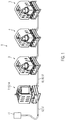
- Fig. 1 shows three control units 3, 4 and 5 arranged one after the other in series, which are connected via a cable connection 17 to one another and to a converter unit 2.
- the converter unit 2 is arranged in an area difficult to access, for instance on the seabed. It is for example connected via a coaxial cable 12 to a monitoring and supplying device 11 that is e.g. arranged on the seabed together with a converter unit 2.
- the distance to be covered via the cable connection 12 may amount up to several 100 kilometers.
- This d.c. voltage supply is transformed by a voltage converter 14 arranged in the converter unit 2 into supply voltages suited for the corresponding control units 3, 4 and 5, for instance d.c. voltages in the order of a few 100 V, particularly about 300 V.
- the corresponding data or signals are picked up in the converter unit 2 by means of a corresponding data separation device 13 and transmitted via the cable 17 to the downstream control units 3, 4, and 5.
- the corresponding data or signals are selectively assigned to the corresponding control unit, a data bus connection, such as a field bus and particularly a CAN bus 16, being used for transmitting the data or signals.
- a data bus connection such as a field bus and particularly a CAN bus 16
- up to 128 addresses can be addressed via this field or CAN bus 16
- up to three or four control units can be addressed via a converter unit in the case of 30 to 40 addresses per control unit 3, 4, and 5.
- the distance between control unit 3 and converter unit 2 and also the distance of the further control units 4 and 5 depends on the data transmission rate used by means of the field or CAN bus. At low data transmission rates correspondingly large line lengths are possible, whereas these are smaller at higher data transmission rates.
- control units 3, 4, 5 it is also possible to transmit specific data or signals to all control units 3, 4, 5, if these serve, for instance, the group control of said control units.
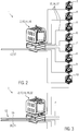
- Fig. 2 shows a further embodiment of a power and signal distribution system 1 according to the invention.
- eight control units 3 to 10 are connected in parallel with a converter unit 2.
- the connection between control units and converter unit is established by analogy with Fig. 1 , with a corresponding connection being provided between each control unit 3 to 10 and the converter unit 2 in the form of a cable 17, in particular, for voltage and signal supply.
- the converter unit 2 comprises a so-called router 18.
- Said router substantially forms some kind of distributing device which forwards incoming data or signals to specific target networks, or in the present case to control units, this process being called routing.
- the cable connection 12 in Fig. 2 is built up by analogy with Fig. 1 and the values regarding voltage, distance, or the like, are also like those of Fig. 1 .
- Fig. 3 shows a further embodiment of a power and signal distribution system 1 of the invention. This system differs from the system according to Fig. 2 , particularly in the way how the data or signals are forwarded.
- a separate cable connection 20 is provided for signal transmission, said cable connection 20 together with the power cable connection 19 forming the corresponding cable connection 12 to the monitoring and supplying device 1.
- the signal cable connection 20 is designed as a fiber cable 21, see also Fig. 5 .
- the values for voltage, distance, or the like, correspond again to those of Figs. 1 and 2 .
- corresponding control units 3 to 10 are not shown for the sake of simplicity. It should additionally be noted that corresponding fiber cables 21 may be braided with power cable connection 19 to form the cable connection 12, wherein for instance ten power cables 19 and a corresponding number of ten signal cable connections 20 may be provided.
- the number of control units 3 to 10 which can be fed by a converter unit 2 is substantially only determined by the capacity of the converter unit, so that for example, eight, nine, ten or more control units can be supplied by only one converter unit 2 with energy/power and data/signals.
- such a converter unit may be arranged approximately in the center of the oil field, the corresponding monitoring and supplying devices 11 being possibly arranged several 100 kilometers away from said place.
- the corresponding control units 3 to 10 can then be arranged relative to the converter unit and distributed over the oil field for exploring substantially the whole oil field.
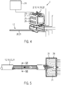
- a separate voltage supply device 24 is used for voltage supply.
- This separate voltage supply device 24 may already be used on site for instance to feed other devices such as pumps or the like. If this separate voltage supply device 24 is adequately designed for the supply of the corresponding components, it can also be used for the additional supply of the converter unit 2.
- the remaining connections between converter unit 2 and control units 3 to 10 are again by analogy particularly with Figs. 2 and 3 . It should here also be noted that it is also possible to replace one of the control units 3 to 10 according to Fig. 2 , or also a plurality of said control units, by a group of control units that are arranged one after the other according to Fig. 1 .
- safety measures refer, for instance, to the arrangement of a power controller 31 in or on the converter unit 2. This power controller monitors the voltage transmitted to the converter unit 2 via power feeding 23 from the separate voltage supply device 24 and controls the voltage to assume values needed by the converter unit 2.
- an EMC module 26 may additionally be assigned to the converter unit 2. Such a module serves here to suppress power-induced failures.
- the converter unit 2 comprises a fiber optic modem 22.
- Said modem serves to convert the data or signals transmitted via the corresponding fiber cable 21 into electrical data or signals and to transmit them (see also the observation regarding Fig. 1 ) via a cable and a corresponding field bus to the connected control units 3 to 10.
- Fig. 5 is an enlarged view of a corresponding cable connection 12 with a fiber cable 21 as a signal cable connection 20.
- a corresponding cable connector 28 is arranged at the end of the cable connection 12 assigned to the converter unit 2.
- the various fiber cables 21 and thus also power cable connections 19 are connectable by said connector also below sea level to a corresponding plug of the converter unit 2.
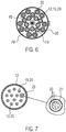
- FIG. 6 A corresponding side view of the cable connector 28 from the right side in Fig. 5 is shown in Fig. 6 .
- ten power cable connections 19 and thus ten signal cable connections 20 in the form of fiber cables 21 and the associated connectors, respectively, can be seen in said figure. These are connected with a corresponding mating connector to the converter unit 2.
- Fig. 7 shows a section taken along line VII-VII of Fig. 5 .
- a total of twelve power cable/signal cable connections 19, 20 are provided, said structure being also analogously applicable to a fiber cable 21, see Figs. 3 and 4 , on condition that according to Fig. 4 no voltage supply takes place through the corresponding cable connection 12.
- a voltage and signal transmission takes place through each of the individual cables shown in sectional view because the corresponding power cable connections 19 and signal cable connections 20 are combined to form said individual cables.
- Ten of said individual cables are used for corresponding control units 3 to 10 while two of said individual cables are configured as substitute lines 29.
- the corresponding individual cables only comprise signal cable connections in the form of fiber cables 21.
- Fig. 7 shows such an individual cable 27 on an enlarged scale, comprising nine fibers 30 and being designed as a coaxial cable that simultaneously serves the transmission of the corresponding voltage.
Claims (15)
- Un système de distribution de puissance et de signal (1) qui comprend une pluralité d'unités de convertisseur et de commande (2, 3), qui sont notamment disposées dans des zones difficiles d'accès, par exemple sur le fond océanique, au moins une unité de commande (3 à 10) étant reliée à au moins une unité de convertisseur (2) et ladite unité de convertisseur (2) étant elle-même reliée à un dispositif distant de surveillance et d'alimentation (11) via au moins une liaison par câble (12), chaque unité de commande (3 à 10) ayant affecté à cet effet sur le site au moins un arbre de production de pétrole brut ou de gaz naturel comprenant des moyens correspondants tels que des robinets-vannes, des duses, des actionneurs etc.,
caractérisé en
ce qu'une pluralité des unités de commande (3 à 10) sont reliées à une unité de convertisseur (2), chacune servant à transmettre de la puissance et des signaux ou données, ladite unité de convertisseur (2) comprenant au moins un dispositif de séparation des données (13) configuré pour séparer les données reçues de l'énergie fournie pour les unités de commande respectives et un convertisseur de tension (14), configuré pour convertir la tension de l'énergie reçue en même temps que les données sont séparées, la tension convertie de chaque unité de tension (3 à 10) pouvant être transmise en même temps que les données/signaux destinés à l'unité de commande respective (3 à 10). - Le système de distribution de puissance et de signal selon la revendication 1, caractérisé en ce que les unités de commande (3, 4, 5) sont disposées l'une après l'autre par rapport à l'unité de convertisseur (2) pour l'alimentation de puissance et sont reliées via une connexion de bus de données (15) aux fins de communication ; de préférence dans lequel l'alimentation et la connexion de bus de données (15) sont intégrées dans un câble; et/ou dans lequel la connexion de bus de données (15) est un bus de terrain (16), notamment un bus Can.
- Le système de distribution de puissance et de signal selon l'une quelconque des revendications précédentes, caractérisé en ce que les unités de commande (3 à 10) sont adressables, notamment individuellement, via la connexion de bus de données (15).
- Le système de distribution de puissance et de signal selon l'une quelconque des revendications précédentes, caractérisé en ce que prend place la conversion de tension de jusqu'à 10 kV à environ 300 V avec le convertisseur de tension (14).
- Le système de distribution de puissance et de signal selon l'une quelconque des revendications précédentes, caractérisé en ce que la distance entre les unités (2 à 10) s'élève à jusqu'à cinq kilomètres ou plus quand la quantité de données transmises s'élève à juste quelques kbits.
- Le système de distribution de puissance et de signal selon l'une quelconque des revendications précédentes, caractérisé en ce que les unités (2 à 10) sont disposées de manière redondante dans au moins deux groupes.
- Le système de distribution de puissance et de signal selon l'une quelconque des revendications précédentes, caractérisé en ce que la connexion par câble (12) entre le dispositif de surveillance et d'alimentation (11) et chaque unité de convertisseur (2) est un câble coaxial.
- Le système de distribution de puissance et de signal selon l'une quelconque des revendications précédentes, caractérisé en ce qu'une pluralité des unités de commande (3 à 10) sont reliées en parallèle à une unité de convertisseur (2).
- Le système de distribution de puissance et de signal selon l'une quelconque des revendications précédentes, caractérisé en ce que l'unité de convertisseur (2) comprend un routeur (18) pour la distribution des données/signaux aux unités de commande respectives (3 à 10).
- Le système de distribution de puissance et de signal selon la revendication 9, caractérisé en ce qu'un modem à fibres optiques (22) est affecté au routeur (18).
- Le système de distribution de puissance et de signal selon l'une quelconque des revendications précédentes, caractérisé en ce que la connexion par câble (12) comprend une pluralité de connexions de câble d'alimentation (19) et de connexions de câble de signal (20).
- Le système de distribution de puissance et de signal selon la revendication 10, caractérisé en ce que la connexion de câble de signal (20) est un câble à fibres optiques (21) ; de préférence dans lequel le câble à fibres optiques (21) comprend une pluralité de câbles monofibre (27).
- Le système de distribution de puissance et de signal selon l'une quelconque des revendications précédentes, caractérisé en ce que l'unité de convertisseur (2) comprend un dispositif d'alimentation de puissance (23) pour l'alimentation en tension supplémentaire (24), et/ou l'unité de convertisseur (2) comprend un régulateur de puissance (25) ; de préférence en ce qu'un module EMC (26) est affecté au routeur (18), modem (22) et/ou au régulateur de puissance (25).
- Le système de distribution de puissance et de signal selon l'une quelconque des revendications précédentes, caractérisé en ce que la connexion par câble (12) comprend un connecteur de câble (28) à connecteurs individuels séparés pour chaque câble monofibre et chaque connexion de câble de puissance.
- Le système de distribution de puissance et de signal selon l'une quelconque des revendications précédentes, caractérisé en ce qu'au moins un câble monofibre de remplacement est prévu dans la connexion par câble (12).
Priority Applications (1)
| Application Number | Priority Date | Filing Date | Title |
|---|---|---|---|
| EP13002494.6A EP2627012B1 (fr) | 2007-05-30 | 2007-05-30 | Système de distribution de puissance et de signal |
Applications Claiming Priority (1)
| Application Number | Priority Date | Filing Date | Title |
|---|---|---|---|
| PCT/EP2007/004793 WO2008145160A1 (fr) | 2007-05-30 | 2007-05-30 | Système de distribution de puissance et de signal |
Related Child Applications (2)
| Application Number | Title | Priority Date | Filing Date |
|---|---|---|---|
| EP13002494.6A Division EP2627012B1 (fr) | 2007-05-30 | 2007-05-30 | Système de distribution de puissance et de signal |
| EP13002494.6A Division-Into EP2627012B1 (fr) | 2007-05-30 | 2007-05-30 | Système de distribution de puissance et de signal |
Publications (2)
| Publication Number | Publication Date |
|---|---|
| EP2160845A1 EP2160845A1 (fr) | 2010-03-10 |
| EP2160845B1 true EP2160845B1 (fr) | 2018-10-03 |
Family
ID=38326201
Family Applications (2)
| Application Number | Title | Priority Date | Filing Date |
|---|---|---|---|
| EP13002494.6A Revoked EP2627012B1 (fr) | 2007-05-30 | 2007-05-30 | Système de distribution de puissance et de signal |
| EP07725682.4A Revoked EP2160845B1 (fr) | 2007-05-30 | 2007-05-30 | Système de distribution de puissance et de signal |
Family Applications Before (1)
| Application Number | Title | Priority Date | Filing Date |
|---|---|---|---|
| EP13002494.6A Revoked EP2627012B1 (fr) | 2007-05-30 | 2007-05-30 | Système de distribution de puissance et de signal |
Country Status (5)
| Country | Link |
|---|---|
| US (2) | US8264370B2 (fr) |
| EP (2) | EP2627012B1 (fr) |
| BR (1) | BRPI0721632A2 (fr) |
| NO (1) | NO343955B1 (fr) |
| WO (1) | WO2008145160A1 (fr) |
Families Citing this family (8)
| Publication number | Priority date | Publication date | Assignee | Title |
|---|---|---|---|---|
| EP2627012B1 (fr) | 2007-05-30 | 2019-04-24 | OneSubsea IP UK Limited | Système de distribution de puissance et de signal |
| WO2011113449A1 (fr) | 2010-03-18 | 2011-09-22 | Cameron International Corporation | Unité de commande et d'alimentation |
| NO346352B1 (no) | 2010-03-18 | 2022-06-20 | Onesubsea Ip Uk Ltd | Regulerings- og forsyningsenhet |
| TWM397665U (en) * | 2010-04-20 | 2011-02-01 | Cable Vision Electronics Co Ltd | Base band-type Ethernet extender transmitted through coaxial cable and powered by PoE |
| WO2012097142A2 (fr) * | 2011-01-12 | 2012-07-19 | Tait Towers, Inc. | Système de fourniture de puissance et de signaux de commande à des dispositifs |
| AU2011373423A1 (en) * | 2011-07-20 | 2014-02-27 | Cameron International Corporation | Energy and data distribution system |
| WO2014059129A1 (fr) * | 2012-10-10 | 2014-04-17 | Deublin Company | Plateforme sans fil pour raccord rotatif |
| FR3022705B1 (fr) * | 2014-06-18 | 2017-07-14 | Bernard Controls | Systeme de commande d'au moins un servomoteur a partir d'un centre de controle / commande |
Family Cites Families (19)
| Publication number | Priority date | Publication date | Assignee | Title |
|---|---|---|---|---|
| US3659280A (en) * | 1967-11-20 | 1972-04-25 | Dantronics Inc | Communication system using the electrical power distribution network of a building |
| NO307666B1 (no) | 1991-12-16 | 2000-05-08 | Inst Francais Du Petrole | Stasjonært system for aktiv eller passiv overvÕkning av en avsetning i undergrunnen |
| NO174488C (no) | 1992-02-12 | 1994-05-11 | Alcatel Stk As | Kabel for overföring av kraft og signaler |
| US7176589B2 (en) | 1995-09-22 | 2007-02-13 | Input/Output, Inc. | Electrical power distribution and communication system for an underwater cable |
| GB2332220B (en) | 1997-12-10 | 2000-03-15 | Abb Seatec Ltd | An underwater hydrocarbon production system |
| GB0105856D0 (en) | 2001-03-09 | 2001-04-25 | Alpha Thames Ltd | Power connection to and/or control of wellhead trees |
| NO314708B1 (no) * | 2001-05-30 | 2003-05-05 | Statoil Asa | Signaloverföring under vann |
| US20030108351A1 (en) | 2001-09-24 | 2003-06-12 | Feinberg Lee Daniel | Methods for ultra long-haul optical communications |
| US7301474B2 (en) | 2001-11-28 | 2007-11-27 | Schlumberger Technology Corporation | Wireless communication system and method |
| GB2382600B (en) | 2001-12-03 | 2005-05-11 | Abb Offshore Systems Ltd | Transmitting power to an underwater hydrocarbon production system |
| US7011152B2 (en) | 2002-02-11 | 2006-03-14 | Vetco Aibel As | Integrated subsea power pack for drilling and production |
| JP4344791B2 (ja) | 2002-10-21 | 2009-10-14 | 日本電気株式会社 | 海底ケーブルシステム及び海底給電分岐装置 |
| GB2396086C (en) | 2002-12-03 | 2007-11-02 | Vetco Gray Controls Ltd | A system for use in controlling a hydrocarbon production well |
| US7261162B2 (en) | 2003-06-25 | 2007-08-28 | Schlumberger Technology Corporation | Subsea communications system |
| GB2417656B (en) | 2004-08-24 | 2009-02-11 | Vetco Gray Controls Ltd | Communication apparatus |
| US7609158B2 (en) * | 2006-10-26 | 2009-10-27 | Cooper Technologies Company | Electrical power system control communications network |
| US7804280B2 (en) * | 2006-11-02 | 2010-09-28 | Current Technologies, Llc | Method and system for providing power factor correction in a power distribution system |
| US7795877B2 (en) * | 2006-11-02 | 2010-09-14 | Current Technologies, Llc | Power line communication and power distribution parameter measurement system and method |
| EP2627012B1 (fr) | 2007-05-30 | 2019-04-24 | OneSubsea IP UK Limited | Système de distribution de puissance et de signal |
-
2007
- 2007-05-30 EP EP13002494.6A patent/EP2627012B1/fr not_active Revoked
- 2007-05-30 BR BRPI0721632-7A patent/BRPI0721632A2/pt not_active IP Right Cessation
- 2007-05-30 EP EP07725682.4A patent/EP2160845B1/fr not_active Revoked
- 2007-05-30 US US12/601,740 patent/US8264370B2/en active Active
- 2007-05-30 WO PCT/EP2007/004793 patent/WO2008145160A1/fr active Application Filing
-
2009
- 2009-09-01 NO NO20092916A patent/NO343955B1/no unknown
-
2012
- 2012-08-09 US US13/571,179 patent/US8552884B2/en active Active
Non-Patent Citations (1)
| Title |
|---|
| None * |
Also Published As
| Publication number | Publication date |
|---|---|
| WO2008145160A1 (fr) | 2008-12-04 |
| NO20092916L (no) | 2010-02-26 |
| EP2627012A1 (fr) | 2013-08-14 |
| EP2627012B1 (fr) | 2019-04-24 |
| EP2160845A1 (fr) | 2010-03-10 |
| NO343955B1 (no) | 2019-07-29 |
| US20120299742A1 (en) | 2012-11-29 |
| US8552884B2 (en) | 2013-10-08 |
| US20100289668A1 (en) | 2010-11-18 |
| BRPI0721632A2 (pt) | 2013-02-13 |
| US8264370B2 (en) | 2012-09-11 |
Similar Documents
| Publication | Publication Date | Title |
|---|---|---|
| US8552884B2 (en) | Power and signal distribution system | |
| US7837397B2 (en) | Digital signal media conversion panel | |
| CN101295430B (zh) | 一种可监测多条矿用传送带的光纤通信系统 | |
| US20070007001A1 (en) | Redundant systems for downhole permanent installations | |
| CN104412541A (zh) | 混合式光纤和以太网供电 | |
| EP2354440B1 (fr) | Connexion de communication dans un puits sous-marin | |
| EP3220560B1 (fr) | Concentrateur de données à distance avec interfacé optique | |
| EP2357313A2 (fr) | Module électronique pour un puits sous-marin | |
| CN101512983A (zh) | 用于海底电子模块的路由设施 | |
| US20100303138A1 (en) | Intrinsically Safe DSL Circuit | |
| CN106506080A (zh) | 一种基于核电站给水系统的现场总线系统和方法 | |
| EP2670950B1 (fr) | Système de communication sous-marine | |
| AU2010200561A1 (en) | A subsea well control system | |
| CN103684619A (zh) | 基于光纤的供电与通信方法及系统、供电设备、受电设备 | |
| CN108141483A (zh) | 用于远程无线电头的电力线缆布线连接及相关方法 | |
| CN103025994A (zh) | 海底油气生产系统 | |
| US20080037930A1 (en) | Tappable cable segment for communication infrastructure | |
| WO1998041730A1 (fr) | Agencement d'un systeme de commande d'une production sous-marine | |
| GB2554465A (en) | Umbilical installation method and system | |
| US20140222224A1 (en) | Energy and Data Distribution System |
Legal Events
| Date | Code | Title | Description |
|---|---|---|---|
| PUAI | Public reference made under article 153(3) epc to a published international application that has entered the european phase |
Free format text: ORIGINAL CODE: 0009012 |
|
| 17P | Request for examination filed |
Effective date: 20091218 |
|
| AK | Designated contracting states |
Kind code of ref document: A1 Designated state(s): AT BE BG CH CY CZ DE DK EE ES FI FR GB GR HU IE IS IT LI LT LU LV MC MT NL PL PT RO SE SI SK TR |
|
| AX | Request for extension of the european patent |
Extension state: AL BA HR MK RS |
|
| DAX | Request for extension of the european patent (deleted) | ||
| 17Q | First examination report despatched |
Effective date: 20120905 |
|
| RAP1 | Party data changed (applicant data changed or rights of an application transferred) |
Owner name: ONESUBSEA IP UK LIMITED |
|
| STAA | Information on the status of an ep patent application or granted ep patent |
Free format text: STATUS: EXAMINATION IS IN PROGRESS |
|
| GRAP | Despatch of communication of intention to grant a patent |
Free format text: ORIGINAL CODE: EPIDOSNIGR1 |
|
| STAA | Information on the status of an ep patent application or granted ep patent |
Free format text: STATUS: GRANT OF PATENT IS INTENDED |
|
| INTG | Intention to grant announced |
Effective date: 20180502 |
|
| GRAS | Grant fee paid |
Free format text: ORIGINAL CODE: EPIDOSNIGR3 |
|
| GRAA | (expected) grant |
Free format text: ORIGINAL CODE: 0009210 |
|
| STAA | Information on the status of an ep patent application or granted ep patent |
Free format text: STATUS: THE PATENT HAS BEEN GRANTED |
|
| AK | Designated contracting states |
Kind code of ref document: B1 Designated state(s): AT BE BG CH CY CZ DE DK EE ES FI FR GB GR HU IE IS IT LI LT LU LV MC MT NL PL PT RO SE SI SK TR |
|
| REG | Reference to a national code |
Ref country code: GB Ref legal event code: FG4D |
|
| REG | Reference to a national code |
Ref country code: CH Ref legal event code: EP Ref country code: AT Ref legal event code: REF Ref document number: 1049746 Country of ref document: AT Kind code of ref document: T Effective date: 20181015 |
|
| REG | Reference to a national code |
Ref country code: DE Ref legal event code: R096 Ref document number: 602007056351 Country of ref document: DE Ref country code: IE Ref legal event code: FG4D |
|
| REG | Reference to a national code |
Ref country code: NL Ref legal event code: MP Effective date: 20181003 |
|
| REG | Reference to a national code |
Ref country code: LT Ref legal event code: MG4D |
|
| REG | Reference to a national code |
Ref country code: AT Ref legal event code: MK05 Ref document number: 1049746 Country of ref document: AT Kind code of ref document: T Effective date: 20181003 |
|
| PG25 | Lapsed in a contracting state [announced via postgrant information from national office to epo] |
Ref country code: NL Free format text: LAPSE BECAUSE OF FAILURE TO SUBMIT A TRANSLATION OF THE DESCRIPTION OR TO PAY THE FEE WITHIN THE PRESCRIBED TIME-LIMIT Effective date: 20181003 |
|
| PG25 | Lapsed in a contracting state [announced via postgrant information from national office to epo] |
Ref country code: IS Free format text: LAPSE BECAUSE OF FAILURE TO SUBMIT A TRANSLATION OF THE DESCRIPTION OR TO PAY THE FEE WITHIN THE PRESCRIBED TIME-LIMIT Effective date: 20190203 Ref country code: FI Free format text: LAPSE BECAUSE OF FAILURE TO SUBMIT A TRANSLATION OF THE DESCRIPTION OR TO PAY THE FEE WITHIN THE PRESCRIBED TIME-LIMIT Effective date: 20181003 Ref country code: CZ Free format text: LAPSE BECAUSE OF FAILURE TO SUBMIT A TRANSLATION OF THE DESCRIPTION OR TO PAY THE FEE WITHIN THE PRESCRIBED TIME-LIMIT Effective date: 20181003 Ref country code: ES Free format text: LAPSE BECAUSE OF FAILURE TO SUBMIT A TRANSLATION OF THE DESCRIPTION OR TO PAY THE FEE WITHIN THE PRESCRIBED TIME-LIMIT Effective date: 20181003 Ref country code: BG Free format text: LAPSE BECAUSE OF FAILURE TO SUBMIT A TRANSLATION OF THE DESCRIPTION OR TO PAY THE FEE WITHIN THE PRESCRIBED TIME-LIMIT Effective date: 20190103 Ref country code: PL Free format text: LAPSE BECAUSE OF FAILURE TO SUBMIT A TRANSLATION OF THE DESCRIPTION OR TO PAY THE FEE WITHIN THE PRESCRIBED TIME-LIMIT Effective date: 20181003 Ref country code: LV Free format text: LAPSE BECAUSE OF FAILURE TO SUBMIT A TRANSLATION OF THE DESCRIPTION OR TO PAY THE FEE WITHIN THE PRESCRIBED TIME-LIMIT Effective date: 20181003 Ref country code: LT Free format text: LAPSE BECAUSE OF FAILURE TO SUBMIT A TRANSLATION OF THE DESCRIPTION OR TO PAY THE FEE WITHIN THE PRESCRIBED TIME-LIMIT Effective date: 20181003 Ref country code: AT Free format text: LAPSE BECAUSE OF FAILURE TO SUBMIT A TRANSLATION OF THE DESCRIPTION OR TO PAY THE FEE WITHIN THE PRESCRIBED TIME-LIMIT Effective date: 20181003 |
|
| PG25 | Lapsed in a contracting state [announced via postgrant information from national office to epo] |
Ref country code: PT Free format text: LAPSE BECAUSE OF FAILURE TO SUBMIT A TRANSLATION OF THE DESCRIPTION OR TO PAY THE FEE WITHIN THE PRESCRIBED TIME-LIMIT Effective date: 20190203 Ref country code: GR Free format text: LAPSE BECAUSE OF FAILURE TO SUBMIT A TRANSLATION OF THE DESCRIPTION OR TO PAY THE FEE WITHIN THE PRESCRIBED TIME-LIMIT Effective date: 20190104 Ref country code: SE Free format text: LAPSE BECAUSE OF FAILURE TO SUBMIT A TRANSLATION OF THE DESCRIPTION OR TO PAY THE FEE WITHIN THE PRESCRIBED TIME-LIMIT Effective date: 20181003 |
|
| REG | Reference to a national code |
Ref country code: DE Ref legal event code: R026 Ref document number: 602007056351 Country of ref document: DE |
|
| PLBI | Opposition filed |
Free format text: ORIGINAL CODE: 0009260 |
|
| PLAX | Notice of opposition and request to file observation + time limit sent |
Free format text: ORIGINAL CODE: EPIDOSNOBS2 |
|
| PG25 | Lapsed in a contracting state [announced via postgrant information from national office to epo] |
Ref country code: IT Free format text: LAPSE BECAUSE OF FAILURE TO SUBMIT A TRANSLATION OF THE DESCRIPTION OR TO PAY THE FEE WITHIN THE PRESCRIBED TIME-LIMIT Effective date: 20181003 Ref country code: DK Free format text: LAPSE BECAUSE OF FAILURE TO SUBMIT A TRANSLATION OF THE DESCRIPTION OR TO PAY THE FEE WITHIN THE PRESCRIBED TIME-LIMIT Effective date: 20181003 |
|
| 26 | Opposition filed |
Opponent name: GE OIL & GAS UK LIMITED Effective date: 20190703 |
|
| PG25 | Lapsed in a contracting state [announced via postgrant information from national office to epo] |
Ref country code: EE Free format text: LAPSE BECAUSE OF FAILURE TO SUBMIT A TRANSLATION OF THE DESCRIPTION OR TO PAY THE FEE WITHIN THE PRESCRIBED TIME-LIMIT Effective date: 20181003 Ref country code: SK Free format text: LAPSE BECAUSE OF FAILURE TO SUBMIT A TRANSLATION OF THE DESCRIPTION OR TO PAY THE FEE WITHIN THE PRESCRIBED TIME-LIMIT Effective date: 20181003 Ref country code: RO Free format text: LAPSE BECAUSE OF FAILURE TO SUBMIT A TRANSLATION OF THE DESCRIPTION OR TO PAY THE FEE WITHIN THE PRESCRIBED TIME-LIMIT Effective date: 20181003 |
|
| PG25 | Lapsed in a contracting state [announced via postgrant information from national office to epo] |
Ref country code: SI Free format text: LAPSE BECAUSE OF FAILURE TO SUBMIT A TRANSLATION OF THE DESCRIPTION OR TO PAY THE FEE WITHIN THE PRESCRIBED TIME-LIMIT Effective date: 20181003 |
|
| PLBB | Reply of patent proprietor to notice(s) of opposition received |
Free format text: ORIGINAL CODE: EPIDOSNOBS3 |
|
| REG | Reference to a national code |
Ref country code: DE Ref legal event code: R119 Ref document number: 602007056351 Country of ref document: DE |
|
| REG | Reference to a national code |
Ref country code: CH Ref legal event code: PL |
|
| PG25 | Lapsed in a contracting state [announced via postgrant information from national office to epo] |
Ref country code: LI Free format text: LAPSE BECAUSE OF NON-PAYMENT OF DUE FEES Effective date: 20190531 Ref country code: CH Free format text: LAPSE BECAUSE OF NON-PAYMENT OF DUE FEES Effective date: 20190531 Ref country code: MC Free format text: LAPSE BECAUSE OF FAILURE TO SUBMIT A TRANSLATION OF THE DESCRIPTION OR TO PAY THE FEE WITHIN THE PRESCRIBED TIME-LIMIT Effective date: 20181003 |
|
| REG | Reference to a national code |
Ref country code: BE Ref legal event code: MM Effective date: 20190531 |
|
| PG25 | Lapsed in a contracting state [announced via postgrant information from national office to epo] |
Ref country code: LU Free format text: LAPSE BECAUSE OF NON-PAYMENT OF DUE FEES Effective date: 20190530 |
|
| PG25 | Lapsed in a contracting state [announced via postgrant information from national office to epo] |
Ref country code: TR Free format text: LAPSE BECAUSE OF FAILURE TO SUBMIT A TRANSLATION OF THE DESCRIPTION OR TO PAY THE FEE WITHIN THE PRESCRIBED TIME-LIMIT Effective date: 20181003 |
|
| PLAB | Opposition data, opponent's data or that of the opponent's representative modified |
Free format text: ORIGINAL CODE: 0009299OPPO |
|
| PG25 | Lapsed in a contracting state [announced via postgrant information from national office to epo] |
Ref country code: DE Free format text: LAPSE BECAUSE OF NON-PAYMENT OF DUE FEES Effective date: 20191203 Ref country code: IE Free format text: LAPSE BECAUSE OF NON-PAYMENT OF DUE FEES Effective date: 20190530 |
|
| R26 | Opposition filed (corrected) |
Opponent name: GE OIL & GAS UK LIMITED Effective date: 20190703 |
|
| PG25 | Lapsed in a contracting state [announced via postgrant information from national office to epo] |
Ref country code: BE Free format text: LAPSE BECAUSE OF NON-PAYMENT OF DUE FEES Effective date: 20190531 |
|
| PG25 | Lapsed in a contracting state [announced via postgrant information from national office to epo] |
Ref country code: FR Free format text: LAPSE BECAUSE OF NON-PAYMENT OF DUE FEES Effective date: 20190531 |
|
| PLAB | Opposition data, opponent's data or that of the opponent's representative modified |
Free format text: ORIGINAL CODE: 0009299OPPO |
|
| R26 | Opposition filed (corrected) |
Opponent name: GE OIL & GAS UK LIMITED Effective date: 20190703 |
|
| PG25 | Lapsed in a contracting state [announced via postgrant information from national office to epo] |
Ref country code: CY Free format text: LAPSE BECAUSE OF FAILURE TO SUBMIT A TRANSLATION OF THE DESCRIPTION OR TO PAY THE FEE WITHIN THE PRESCRIBED TIME-LIMIT Effective date: 20181003 |
|
| PG25 | Lapsed in a contracting state [announced via postgrant information from national office to epo] |
Ref country code: MT Free format text: LAPSE BECAUSE OF FAILURE TO SUBMIT A TRANSLATION OF THE DESCRIPTION OR TO PAY THE FEE WITHIN THE PRESCRIBED TIME-LIMIT Effective date: 20181003 Ref country code: HU Free format text: LAPSE BECAUSE OF FAILURE TO SUBMIT A TRANSLATION OF THE DESCRIPTION OR TO PAY THE FEE WITHIN THE PRESCRIBED TIME-LIMIT; INVALID AB INITIO Effective date: 20070530 |
|
| RDAF | Communication despatched that patent is revoked |
Free format text: ORIGINAL CODE: EPIDOSNREV1 |
|
| REG | Reference to a national code |
Ref country code: DE Ref legal event code: R103 Ref document number: 602007056351 Country of ref document: DE Ref country code: DE Ref legal event code: R064 Ref document number: 602007056351 Country of ref document: DE |
|
| RDAG | Patent revoked |
Free format text: ORIGINAL CODE: 0009271 |
|
| STAA | Information on the status of an ep patent application or granted ep patent |
Free format text: STATUS: PATENT REVOKED |
|
| REG | Reference to a national code |
Ref country code: CH Ref legal event code: PL |
|
| REG | Reference to a national code |
Ref country code: FI Ref legal event code: MGE |
|
| 27W | Patent revoked |
Effective date: 20220307 |
|
| GBPR | Gb: patent revoked under art. 102 of the ep convention designating the uk as contracting state |
Effective date: 20220307 |
|
| PGFP | Annual fee paid to national office [announced via postgrant information from national office to epo] |
Ref country code: GB Payment date: 20220407 Year of fee payment: 16 |
|
| P01 | Opt-out of the competence of the unified patent court (upc) registered |
Effective date: 20231212 |