EP2160252B1 - Self regulating vent for a paint supply vessel - Google Patents
Self regulating vent for a paint supply vessel Download PDFInfo
- Publication number
- EP2160252B1 EP2160252B1 EP08760690A EP08760690A EP2160252B1 EP 2160252 B1 EP2160252 B1 EP 2160252B1 EP 08760690 A EP08760690 A EP 08760690A EP 08760690 A EP08760690 A EP 08760690A EP 2160252 B1 EP2160252 B1 EP 2160252B1
- Authority
- EP
- European Patent Office
- Prior art keywords
- vessel
- valve
- closure lid
- air inlet
- openings
- Prior art date
- Legal status (The legal status is an assumption and is not a legal conclusion. Google has not performed a legal analysis and makes no representation as to the accuracy of the status listed.)
- Active
Links
Images


Classifications
-
- B—PERFORMING OPERATIONS; TRANSPORTING
- B05—SPRAYING OR ATOMISING IN GENERAL; APPLYING FLUENT MATERIALS TO SURFACES, IN GENERAL
- B05B—SPRAYING APPARATUS; ATOMISING APPARATUS; NOZZLES
- B05B7/00—Spraying apparatus for discharge of liquids or other fluent materials from two or more sources, e.g. of liquid and air, of powder and gas
- B05B7/24—Spraying apparatus for discharge of liquids or other fluent materials from two or more sources, e.g. of liquid and air, of powder and gas with means, e.g. a container, for supplying liquid or other fluent material to a discharge device
- B05B7/2402—Apparatus to be carried on or by a person, e.g. by hand; Apparatus comprising containers fixed to the discharge device
- B05B7/2405—Apparatus to be carried on or by a person, e.g. by hand; Apparatus comprising containers fixed to the discharge device using an atomising fluid as carrying fluid for feeding, e.g. by suction or pressure, a carried liquid from the container to the nozzle
- B05B7/2408—Apparatus to be carried on or by a person, e.g. by hand; Apparatus comprising containers fixed to the discharge device using an atomising fluid as carrying fluid for feeding, e.g. by suction or pressure, a carried liquid from the container to the nozzle characterised by the container or its attachment means to the spray apparatus
-
- B—PERFORMING OPERATIONS; TRANSPORTING
- B05—SPRAYING OR ATOMISING IN GENERAL; APPLYING FLUENT MATERIALS TO SURFACES, IN GENERAL
- B05B—SPRAYING APPARATUS; ATOMISING APPARATUS; NOZZLES
- B05B7/00—Spraying apparatus for discharge of liquids or other fluent materials from two or more sources, e.g. of liquid and air, of powder and gas
- B05B7/24—Spraying apparatus for discharge of liquids or other fluent materials from two or more sources, e.g. of liquid and air, of powder and gas with means, e.g. a container, for supplying liquid or other fluent material to a discharge device
- B05B7/2402—Apparatus to be carried on or by a person, e.g. by hand; Apparatus comprising containers fixed to the discharge device
- B05B7/2478—Gun with a container which, in normal use, is located above the gun
Definitions
- the present invention relates to a vessel, in particular for containing paint, comprising a reservoir and a closure lid which reservoir is provided for being closed by said closure lid, which closure lid is applicable on top of a liquid application tool, said vessel having an air inlet comprising a plurality of openings, said closure lid comprises a conically shaped part.
- Such a vessel is known from the International Patent application WO 03/006170 .
- the latter application relates to a vessel being mounted on top of a liquid application tool.
- gravity helps feeding the liquid into the application tool.
- the vessel also comprises a conically shaped part, which allows to easily apply a filter between the reservoir and the application tool, which keeps the latter from clogging up.
- the conically shaped part further allows feeding the liquid into the liquid application tool even if the latter is used in a non-horizontal position. Openings are provided on the reservoir to provide vacuum relief for the liquid application tool. This implies that the reservoir is not liquid-tight any more.
- the above mentioned patents therefore describe the use of a flexible liner within the cavity of the reservoir, which liner holds the liquid. The advantage is that the reservoir can be used multiple times.
- a drawback of the known vessel is that it requires an extra element, namely the liner. It also requires at least one extra step using such a vessel, namely placing the flexible liner into the reservoir.
- a vessel according to the present invention is characterised in that said air inlet is provided with a closure valve made of flexible elastomer material, said valve being resiliently mounted on said air inlet in such a manner as to cover said plurality of openings, of which each opening having a surface area of at the most 15 mm 2 , and as to open upon a predetermined pressure difference between a first pressure inside said vessel and a second pressure outside said vessel, said closure lid (3) being provided with a protrusion applied on said conically shaped part and forming a flat contact face for said valve.
- the vessel is capable of holding a liquid because a valve is used to cover the openings.
- the vessel is capable of holding a liquid, there is no need any more for a flexible liner, and the liquid can be applied directly into the reservoir. Because there is no flexible liner, in using the vessel, there is no need to apply such a liner, which makes the use of the vessel easier. No openings are to be provided in the reservoir so as to keep the latter intact and consequently suitable for using multiple times.
- the valve is not applied on the reservoir which forms the top part of the vessel in a mounted position, but the valve is applied on the closure lid. No particular measures are to be applied on the reservoir for vacuum relief, which makes any cup which fits to the closure lid suitable for being used as reservoir.
- the valve is applied on the closure lid, which forms the lower part of the vessel in a mounted position, when air enters the vessel through the valve, the air enters below the liquid surface. This results in bubbles rising to the liquid surface, thereby creating turbulences inside the liquid. These turbulences induce a mixing effect to the liquid, which is especially advantageous in multi component liquids.
- a first preferred embodiment of a vessel according to the present invention is characterised in that said openings are applied along a circumference of a circle and wherein said valve has a circularly shaped member covering said openings.
- the circular distribution of the openings stimulates a well distributed air flow.
- a second preferred embodiment of a vessel according to the present invention is characterised in that a further opening is applied in the centre of said circle, said valve having a stem extending from said member and penetrating into said further opening. In such a manner the stem is surrounded by the air flow openings.
- the invention also relates to a closure lid for a vessel according to the present invention.
- the closure lid having a central opening, being applicable on top of a liquid application tool and comprising a conically shaped part.
- the closure lid according to the invention is characterised by the closure lid having an air inlet comprising a plurality of openings wherein the air inlet is provided with a closure valve made of flexible elastomer material, said valve being resiliently mounted on said air inlet in such a manner as to cover said plurality of openings, of which each opening has a surface area of 15 mm 2 at the most and as to open upon a predetermined pressure difference between a first pressure inside a vessel closed by the lid and a second pressure outside a vessel closed by the lid, said closure lid being provided with a protrusion applied on said conically shaped part, the protrusion forming a flat contact face for said valve.
- the vessel 1 illustrated in figure 1 is mounted on a spray gun 4 provided with a handle 5 for controlling the spray volume.
- a spray gun is used as a liquid application tool. It will however be clear that other application tools than a spray gun can be used.
- the vessel is provided for storing and conveying paint to the spray gun. It will however be clear that the present invention is not limited to vessels for storing paint and that the vessels may contain any other liquid or viscous material to be supplied to the application tool.
- the vessel also comprises a reservoir 2, which is closed by means of a closure lid 3. The closure lid is preferably clicked on a rim of the reservoir with a pressure fit interlocking design.
- the vessel can also comprise a mixing cup which is removably mounted thereto.
- the mixing cup is used for preparing a mixture, in particular paint, prior to pouring it into the vessel, which is subsequently mounted onto the application tool.
- the removably mounted mixing cup enables to incorporate the mixing cup as part of the vessel, thereby avoiding the need to transfer the liquid to another vessel prior to the application thereof. This extends the utility of a mixing cup, reduces waste, and reduces the cost and the number of steps in the liquid (paint) preparation process.
- the closure lid further comprises an air inlet 9.
- the air inlet crosses the closure lid surface 11 and comprises a plurality of openings 10.
- the air inlet is applied approximately half way between the closure rim 6 and the central opening 7.
- the openings are applied along'a circumference of a circle.
- the air inlet is preferably applied on a seat 12.
- the seat 12 forms a triangularly shaped protrusion (as seen in the sectioned view of figure 4 ) inside the vessel and with respect to the cover lid surface 11. By this protrusion, a flat surface is created on which the air inlet can be provided.
- the air inlet location may be adjusted for various reasons, such as to incorporate the aforementioned filtering screen.
- the air inlet is applied on the closure lid.
- the air inlet could also be applied on the reservoir 2, preferably in the upper part thereof.
- the openings 10 are applied in the flat surface part of the seat which extend substantially parallel with respect to line 13. In such a manner, the air penetrates perpendicularly through the openings 10 and turbulences are avoided which would be generated in case that the openings would be applied in the conical surface.
- the air inlet 9 is as if to say applied in a cavity, applied on the closure lid's surface 11.
- FIG 5 which shows a detailed view of the openings
- the dimension of the diameter d1 is determined in function of the liquid to be applied and the amount of air flow needed into the interior of the vessel.
- the diameter of each opening can vary between 0.2 mm to 4 mm.
- At the most each of the plurality of openings have a surface of 15 mm 2 .
- diameter d2 may also vary according to the liquid to be applied and air flow needed into the vessel interior.
- the air inlet is further provided with a closure valve 14 made of a flexible elastomer material such as silicone rubber, fluorosilicone, fluoroelastomers or perfluoroelastomers.
- a closure valve 14 made of a flexible elastomer material such as silicone rubber, fluorosilicone, fluoroelastomers or perfluoroelastomers.
- the choice of the elastomer material of which the valve is made is in function of the liquid that will be present in the vessel. Indeed, care has to be taken that the latter material is chemically resistant to this liquid.
- the valve assembly may also be mounted in the reservoir if the air inlet is applied there.
- the air inlet is preferably provided with a further opening 17 as illustrated in figures 5 and 6 .
- This further opening 17 is applied in a centre of the circle C within which the openings 10 are applied.
- the valve comprises preferably a stem 15 on which a circularly shaped member 16 is mounted as illustrated in figure 6 .
- the circularly shaped member is dimensioned in such a manner that it covers the plurality of openings.
- Such a type of valve is also called an umbrella valve.
- the circularly shaped member 16 extends on the inner side of the closure lid, whereas the stem 15 penetrates through the further opening 17 in order to reach the outer side of the closure lid 3.
- the stem 15 is somewhat compressed inside the further opening 17 so that it bulges out at the outer side, thereby firmly fixing the valve to the air inlet.
- the valve thus covers the openings and opens upon a pressure difference between a first pressure P1 inside the vessel and a second pressure P2 outside the vessel.
- the gun When the user activates the handle 5 of the spray gun, the gun will open thereby causing a pressure drop inside the vessel. As the pressure P1, inside the vessel is then lower than the pressure P2 outside the vessel, a pressure difference will be established over the air inlet, causing the valve to open and thus allowing air from the outside to flow via the plurality of openings 10 inside the vessel. As soon as the handle is released, the pressure difference becomes negligible, thereby causing the valve to close. The valve is thus self regulating and as the valve closes after release of the handle, the vessel is closed and there is no need to change the closure lid, even if the liquid remains stored in the vessel.
- the closure lid and the reservoir are preferably made of plastic disposable material so as to provide a low cost product. Moreover, there is also no need to clean the reservoir. It has to be noted that a silicone valve may swell upon exposure to certain solvents which may be present in the liquid. However this will not affect the operation of the valve as the member 16 does not cross the boundaries of the seat.
- the valve can be designed in such a manner that it opens at predetermined pressure differential between the interior and exterior of the vessel.
- the valve design can be optimized to open at as low as 5 millibar of pressure or as high as 10 KPa, depending on needs of the application.
- the valve has also a self sealing feature, as even without pressure difference the stem holds the valve closed due to the pre-tension in the stem.
- the self regulating properties of the valve cause the air volume passing through the plurality of openings to be directly dependent on the amount of liquid sprayed.
- the size of the valve and seat openings can be increased or multiple valve mountings could be used.
Landscapes
- Closures For Containers (AREA)
- Containers And Packaging Bodies Having A Special Means To Remove Contents (AREA)
Description
- The present invention relates to a vessel, in particular for containing paint, comprising a reservoir and a closure lid which reservoir is provided for being closed by said closure lid, which closure lid is applicable on top of a liquid application tool, said vessel having an air inlet comprising a plurality of openings, said closure lid comprises a conically shaped part.
- Such a vessel is known from the International Patent application
WO 03/006170 - A drawback of the known vessel is that it requires an extra element, namely the liner. It also requires at least one extra step using such a vessel, namely placing the flexible liner into the reservoir.
- It is an object of the present invention to provide a vessel which allows using a reservoir multiple times, and which vessel is easier to use than prior art vessels.
- For this purpose, a vessel according to the present invention is characterised in that said air inlet is provided with a closure valve made of flexible elastomer material, said valve being resiliently mounted on said air inlet in such a manner as to cover said plurality of openings, of which each opening having a surface area of at the most 15 mm2, and as to open upon a predetermined pressure difference between a first pressure inside said vessel and a second pressure outside said vessel, said closure lid (3) being provided with a protrusion applied on said conically shaped part and forming a flat contact face for said valve. Despite the openings, the vessel is capable of holding a liquid because a valve is used to cover the openings. Because the vessel is capable of holding a liquid, there is no need any more for a flexible liner, and the liquid can be applied directly into the reservoir. Because there is no flexible liner, in using the vessel, there is no need to apply such a liner, which makes the use of the vessel easier. No openings are to be provided in the reservoir so as to keep the latter intact and consequently suitable for using multiple times.
- It should be noted that a combination of
WO 03/006170 US Patent 4388997 would not lead to the present invention. A person skilled in the art starting fromWO 03/006170 US Patent 4388997 , as the latter discloses a valve suitable for being used in the present invention. However inWO 03/006170 US Patent 4388997 , the valve is applied above the liquid surface. In combining those documents, a person skilled in the art would come up with the solution to apply the valve on the top part of the vessel in a mounted position. - However the solution provided by the present invention is different from the solution the skilled person could come up with. In the present invention, the valve is not applied on the reservoir which forms the top part of the vessel in a mounted position, but the valve is applied on the closure lid. No particular measures are to be applied on the reservoir for vacuum relief, which makes any cup which fits to the closure lid suitable for being used as reservoir. Moreover the valve is applied on the closure lid, which forms the lower part of the vessel in a mounted position, when air enters the vessel through the valve, the air enters below the liquid surface. This results in bubbles rising to the liquid surface, thereby creating turbulences inside the liquid. These turbulences induce a mixing effect to the liquid, which is especially advantageous in multi component liquids.
- To ensure a duly closing of the valve to the closure lid comprising a conically shaped part, adaptation has to be made. By creating a protrusion on the conically shaped part of the closure lid, a flat surface is obtained on the closure lid. Due to the valve being applied to the flat surface, openings can be duly closed by the valve.
- A first preferred embodiment of a vessel according to the present invention is characterised in that said openings are applied along a circumference of a circle and wherein said valve has a circularly shaped member covering said openings. The circular distribution of the openings stimulates a well distributed air flow.
- A second preferred embodiment of a vessel according to the present invention is characterised in that a further opening is applied in the centre of said circle, said valve having a stem extending from said member and penetrating into said further opening. In such a manner the stem is surrounded by the air flow openings.
- The invention also relates to a closure lid for a vessel according to the present invention. The closure lid having a central opening, being applicable on top of a liquid application tool and comprising a conically shaped part. The closure lid according to the invention is characterised by the closure lid having an air inlet comprising a plurality of openings wherein the air inlet is provided with a closure valve made of flexible elastomer material, said valve being resiliently mounted on said air inlet in such a manner as to cover said plurality of openings, of which each opening has a surface area of 15 mm2 at the most and as to open upon a predetermined pressure difference between a first pressure inside a vessel closed by the lid and a second pressure outside a vessel closed by the lid, said closure lid being provided with a protrusion applied on said conically shaped part, the protrusion forming a flat contact face for said valve.
- The invention will now be described in more details with reference to the drawings showing a preferred embodiment of a vessel according to the invention. In the drawings :
-
figure 1 shows an overall view of the vessel mounted on a spray gun; -
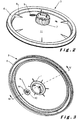
figure 2 shows a top view of the closure lid; -
figure 3 shows the inner side of the closure lid; -
figure 4 shows a cross section along the line IV-IV'; -
figure 5 shows a detailed view of the plurality of holes; and -
figure 6 shows a cross section through the closure valve. - In the drawings a same reference sign has been allocated to a same or analogous element.
- The
vessel 1 illustrated infigure 1 , is mounted on aspray gun 4 provided with ahandle 5 for controlling the spray volume. In this particular example a spray gun is used as a liquid application tool. It will however be clear that other application tools than a spray gun can be used. The vessel is provided for storing and conveying paint to the spray gun. It will however be clear that the present invention is not limited to vessels for storing paint and that the vessels may contain any other liquid or viscous material to be supplied to the application tool. The vessel also comprises areservoir 2, which is closed by means of aclosure lid 3. The closure lid is preferably clicked on a rim of the reservoir with a pressure fit interlocking design. The vessel can also comprise a mixing cup which is removably mounted thereto. The mixing cup is used for preparing a mixture, in particular paint, prior to pouring it into the vessel, which is subsequently mounted onto the application tool. The removably mounted mixing cup enables to incorporate the mixing cup as part of the vessel, thereby avoiding the need to transfer the liquid to another vessel prior to the application thereof. This extends the utility of a mixing cup, reduces waste, and reduces the cost and the number of steps in the liquid (paint) preparation process. - As illustrated in
figure 2 , which shows a top view of theclosure lid 3, the latter comprises aclosure rim 6 for fixing the closure lid on thereservoir 2. The closure rim is upright with respect to theclosure lid surface 11 extending from the closure rim towards acentral opening 7 applied on a protrusion and provided for mounting thevessel 1 on thespray gun 4. Triangularlyshaped reinforcement elements 8 extend as from the closure rim's upright part towards the central opening over a short section of theclosure lid surface 11. The reinforcement elements reinforce the connection between theclosure rim 6 and theclosure lid surface 11 and also the whole closure lid, in such a manner as to firmly sustain the weight of the liquid when the vessel is applied on the application tool. - The closure lid further comprises an
air inlet 9. As illustrated in thefigures 2 and 3 , the air inlet crosses theclosure lid surface 11 and comprises a plurality ofopenings 10. The air inlet is applied approximately half way between theclosure rim 6 and thecentral opening 7. The openings are applied along'a circumference of a circle. As illustrated infigure 4 , the air inlet is preferably applied on aseat 12. Especially when the closure lid comprises a conically shaped part, which is favourable when a filtering screen is mounted, theseat 12 forms a triangularly shaped protrusion (as seen in the sectioned view offigure 4 ) inside the vessel and with respect to thecover lid surface 11. By this protrusion, a flat surface is created on which the air inlet can be provided. The air inlet location may be adjusted for various reasons, such as to incorporate the aforementioned filtering screen. In the illustrated embodiment the air inlet is applied on the closure lid. Alternatively the air inlet could also be applied on thereservoir 2, preferably in the upper part thereof. - The
openings 10 are applied in the flat surface part of the seat which extend substantially parallel with respect toline 13. In such a manner, the air penetrates perpendicularly through theopenings 10 and turbulences are avoided which would be generated in case that the openings would be applied in the conical surface. When seen from the outer side of the closure lid (figure 2 ), theair inlet 9 is as if to say applied in a cavity, applied on the closure lid'ssurface 11. - As is illustrated in
figure 5 , which shows a detailed view of the openings, the latter are rather small and have preferably a diameter d1 = 1,6 mm. The dimension of the diameter d1 is determined in function of the liquid to be applied and the amount of air flow needed into the interior of the vessel. The diameter of each opening can vary between 0.2 mm to 4 mm. At the most each of the plurality of openings have a surface of 15 mm2. Preferably the plurality ofholes 10 are situated inside a circle C having a diameter d2 = 6 mm. However, diameter d2 may also vary according to the liquid to be applied and air flow needed into the vessel interior. - The air inlet is further provided with a
closure valve 14 made of a flexible elastomer material such as silicone rubber, fluorosilicone, fluoroelastomers or perfluoroelastomers. The choice of the elastomer material of which the valve is made, is in function of the liquid that will be present in the vessel. Indeed, care has to be taken that the latter material is chemically resistant to this liquid. Nor is the location of the valve assembly limited to placement in the closure lid, the valve assembly may also be mounted in the reservoir if the air inlet is applied there. - In order to apply the closure valve, the air inlet is preferably provided with a
further opening 17 as illustrated infigures 5 and 6 . This further opening 17 is applied in a centre of the circle C within which theopenings 10 are applied. The valve comprises preferably astem 15 on which a circularly shapedmember 16 is mounted as illustrated infigure 6 . The circularly shaped member is dimensioned in such a manner that it covers the plurality of openings. Such a type of valve is also called an umbrella valve. The circularly shapedmember 16 extends on the inner side of the closure lid, whereas thestem 15 penetrates through thefurther opening 17 in order to reach the outer side of theclosure lid 3. Thestem 15 is somewhat compressed inside thefurther opening 17 so that it bulges out at the outer side, thereby firmly fixing the valve to the air inlet. The valve thus covers the openings and opens upon a pressure difference between a first pressure P1 inside the vessel and a second pressure P2 outside the vessel. - When the user activates the
handle 5 of the spray gun, the gun will open thereby causing a pressure drop inside the vessel. As the pressure P1, inside the vessel is then lower than the pressure P2 outside the vessel, a pressure difference will be established over the air inlet, causing the valve to open and thus allowing air from the outside to flow via the plurality ofopenings 10 inside the vessel. As soon as the handle is released, the pressure difference becomes negligible, thereby causing the valve to close. The valve is thus self regulating and as the valve closes after release of the handle, the vessel is closed and there is no need to change the closure lid, even if the liquid remains stored in the vessel. - The closure lid and the reservoir are preferably made of plastic disposable material so as to provide a low cost product. Moreover, there is also no need to clean the reservoir. It has to be noted that a silicone valve may swell upon exposure to certain solvents which may be present in the liquid. However this will not affect the operation of the valve as the
member 16 does not cross the boundaries of the seat. - The valve can be designed in such a manner that it opens at predetermined pressure differential between the interior and exterior of the vessel. The valve design can be optimized to open at as low as 5 millibar of pressure or as high as 10 KPa, depending on needs of the application. The valve has also a self sealing feature, as even without pressure difference the stem holds the valve closed due to the pre-tension in the stem. The self regulating properties of the valve cause the air volume passing through the plurality of openings to be directly dependent on the amount of liquid sprayed. To increase the flow of air into the vessel, the size of the valve and seat openings can be increased or multiple valve mountings could be used.
Claims (8)
- A vessel (1), in particular for containing paint, comprising a reservoir (2) and a closure lid (3) which reservoir (2) is provided for being closed by said closure lid (3), which closure lid (3) is applicable on top of a liquid application tool (4), said vessel (1) having an air inlet (9) comprising a plurality of openings (10), said closure lid (3) comprises a conically shaped part, characterised in that said air inlet is provided with a closure valve (14) made of flexible elastomer material, said valve being resiliently mounted on said air inlet in such a manner as to cover said plurality of openings, of which each opening having a surface area of at the most 15 mm2, and as to open upon a predetermined pressure difference between a first pressure inside said vessel and a second pressure outside said vessel, said closure lid (3) being provided with a protrusion (12) applied on said conically shaped part and forming a flat contact face for said valve.
- The vessel as claimed in claim 1, characterised in that said openings (10) are applied along a circumference of a circle and wherein said valve has a circularly shaped member (16) covering said openings.
- The vessel as claimed in claim 2, characterised in that a further opening (17) is applied in a centre of said circle, said valve having a stem (15) extending from said member (18) and penetrating into said further opening.
- The vessel as claimed in anyone of the claims 1 to 3, characterised in that said air inlet is applied on a seat formed by a protrusion extending inside said vessel.
- The vessel as claimed in anyone of the claims 1 to 4, characterise in that said air inlet is applied on a seat applied approximately half way between a rim (6) and a centre of said lid.
- The vessel as claimed in anyone of the claims 1 to 5, characterised in that said closure lid (3) is provided for receiving a filtering screen.
- The vessel as claimed in any one of the claims 1 to 6, characterised in that the vessel comprises a mixing cup removably mounted therein.
- A closure lid (3) for a vessel (1) according to any of claims 1 to 7, the closure lid (3) having a central opening (7), being applicable on top of a liquid application tool (4), and comprising a conically shaped part, characterised by the closure lid (3) having an air inlet (9) comprising a plurality of openings (10) wherein the air inlet (9) is provided with a closure valve (14) made of flexible elastomer material, said valve (14) being resiliently mounted on said air inlet (9) in such a manner as to cover said plurality of openings, of which each opening has a surface area of 15 mm2 at the most and as to open upon a predetermined pressure difference between a first pressure inside a vessel closed by the lid (3) and a second pressure outside a vessel closed by the lid (3), said closure lid (3) being provided with a protrusion applied on said conically shaped part, the protrusion forming a flat contact face for said valve (14).
Priority Applications (1)
| Application Number | Priority Date | Filing Date | Title |
|---|---|---|---|
| EP08760690A EP2160252B1 (en) | 2007-06-07 | 2008-06-06 | Self regulating vent for a paint supply vessel |
Applications Claiming Priority (3)
| Application Number | Priority Date | Filing Date | Title |
|---|---|---|---|
| EP07109834A EP2000218A1 (en) | 2007-06-07 | 2007-06-07 | Self regulating vent for a paint supply vessel. |
| EP08760690A EP2160252B1 (en) | 2007-06-07 | 2008-06-06 | Self regulating vent for a paint supply vessel |
| PCT/EP2008/057121 WO2008148887A1 (en) | 2007-06-07 | 2008-06-06 | Self regulating vent for a paint supply vessel |
Publications (2)
| Publication Number | Publication Date |
|---|---|
| EP2160252A1 EP2160252A1 (en) | 2010-03-10 |
| EP2160252B1 true EP2160252B1 (en) | 2013-01-09 |
Family
ID=38459585
Family Applications (2)
| Application Number | Title | Priority Date | Filing Date |
|---|---|---|---|
| EP07109834A Withdrawn EP2000218A1 (en) | 2007-06-07 | 2007-06-07 | Self regulating vent for a paint supply vessel. |
| EP08760690A Active EP2160252B1 (en) | 2007-06-07 | 2008-06-06 | Self regulating vent for a paint supply vessel |
Family Applications Before (1)
| Application Number | Title | Priority Date | Filing Date |
|---|---|---|---|
| EP07109834A Withdrawn EP2000218A1 (en) | 2007-06-07 | 2007-06-07 | Self regulating vent for a paint supply vessel. |
Country Status (5)
| Country | Link |
|---|---|
| US (1) | US20100288772A1 (en) |
| EP (2) | EP2000218A1 (en) |
| CA (1) | CA2689229A1 (en) |
| ES (1) | ES2402594T3 (en) |
| WO (1) | WO2008148887A1 (en) |
Families Citing this family (35)
| Publication number | Priority date | Publication date | Assignee | Title |
|---|---|---|---|---|
| EP1835997B1 (en) | 2004-12-16 | 2012-06-13 | Saint-Gobain Abrasives, Inc. | Liquid supply cup and liner assembly for spray guns |
| DK2029285T3 (en) | 2006-06-20 | 2013-03-11 | Saint Gobain Abrasives Inc | The liquid supply device |
| US11040360B2 (en) | 2006-06-20 | 2021-06-22 | Saint-Gobain Abrasives, Inc. | Liquid supply assembly |
| GB0811050D0 (en) * | 2008-06-17 | 2008-07-23 | U Pol Ltd | A Connector for a gravity feed spray gun, a gravity feed spray gun and a method of preparing a spray paint |
| CA2835088C (en) | 2011-05-06 | 2018-01-16 | Saint-Gobain Abrasives, Inc. | Paint cup assembly with an extended ring |
| ES2739299T3 (en) | 2011-06-30 | 2020-01-30 | Saint Gobain Abrasives Inc | Paint container set |
| CN107262308B (en) * | 2011-10-27 | 2022-07-08 | 固瑞克明尼苏达有限公司 | Sprayer fluid supply system with collapsible liner |
| MX2014007887A (en) | 2011-12-30 | 2014-10-06 | Saint Gobain Abrasives Inc | Convertible paint cup assembly with air inlet valve. |
| JP6694816B2 (en) | 2013-12-05 | 2020-05-20 | スリーエム イノベイティブ プロパティズ カンパニー | Container for spray equipment |
| US9796492B2 (en) | 2015-03-12 | 2017-10-24 | Graco Minnesota Inc. | Manual check valve for priming a collapsible fluid liner for a sprayer |
| JP6807915B2 (en) * | 2015-07-08 | 2021-01-06 | スリーエム イノベイティブ プロパティズ カンパニー | Spray gun cups, containers, and how to use |
| CA3011435A1 (en) * | 2016-01-15 | 2017-07-20 | 3M Innovative Properties Company | Spray gun cups, receptacles, and methods of use |
| CA3011441C (en) | 2016-01-15 | 2024-01-16 | 3M Innovative Properties Company | Wide-mouthed fluid connector for hand-held spray guns |
| ES3032934T3 (en) | 2016-01-15 | 2025-07-29 | 3M Innovative Properties Company | Connector system for hand-held spray guns |
| USD793530S1 (en) * | 2016-03-24 | 2017-08-01 | 3M Innovative Properties Company | Lid for spray gun cup |
| USD811525S1 (en) * | 2016-03-24 | 2018-02-27 | 3M Innovative Properties Company | Retention collar for spray gun cup |
| AU2017207351B2 (en) | 2016-01-15 | 2019-10-31 | 3M Innovative Properties Company | Modular spray gun lid assemblies and methods of design and use |
| WO2017123709A1 (en) | 2016-01-15 | 2017-07-20 | 3M Innovative Properties Company | Spray gun cups, receptacles, lids, and methods of use |
| US10689165B2 (en) | 2016-01-15 | 2020-06-23 | 3M Innovative Properties Company | Reservoir systems for hand-held spray guns and methods of use |
| ITUB201653118U1 (en) | 2016-03-01 | 2017-09-01 | Cartotecnica Basic S N C Di Traverso Ruggero E C | GRAVITY PAINT TANK FOR PAINTING GUN |
| CN110891693B (en) | 2017-07-14 | 2022-07-01 | 3M创新有限公司 | Fluid delivery assembly for spray gun |
| IT201800009634A1 (en) * | 2018-10-19 | 2020-04-19 | Walmec Spa | Improved Paint Tank |
| IT201800010567A1 (en) * | 2018-11-26 | 2020-05-26 | Walmec Spa | Sprayable product tank to feed an airbrush |
| US11326830B2 (en) | 2019-03-22 | 2022-05-10 | Robert W. Jacobi | Multiple module modular systems for refrigeration |
| TWI855085B (en) | 2019-05-31 | 2024-09-11 | 美商葛萊兒明尼蘇達股份有限公司 | Handheld fluid sprayer |
| JP1651759S (en) * | 2019-07-04 | 2020-01-27 | ||
| CN212550094U (en) * | 2019-12-23 | 2021-02-19 | 青岛汉柏塑料科技有限公司 | Spray gun liquid reservoir cover and spray gun liquid reservoir |
| USD937968S1 (en) | 2020-03-12 | 2021-12-07 | 3M Innovative Properties Company | Container |
| USD971725S1 (en) | 2020-03-12 | 2022-12-06 | 3M Innovative Properties Company | Container lid |
| DE102020109913A1 (en) | 2020-04-08 | 2021-10-14 | Sata Gmbh & Co. Kg | Color cups made from natural fiber |
| CN111438020B (en) * | 2020-04-22 | 2024-09-13 | 青岛汉柏塑料科技有限公司 | Storage cups and spray gun fluid reservoirs |
| USD952097S1 (en) * | 2020-07-14 | 2022-05-17 | Yuyao Yufeng Scutcheon Plastic Factory | Paint spraying pot lid |
| DE102020120226A1 (en) * | 2020-07-31 | 2022-02-03 | Sata Gmbh & Co. Kg | Gravity cup for a spray gun with a screw cap |
| DE102020120228A1 (en) | 2020-07-31 | 2022-02-03 | Sata Gmbh & Co. Kg | Gravity cup for a spray gun with an aeration device |
| USD1029185S1 (en) * | 2022-02-23 | 2024-05-28 | Huaian Hohear Tech. Co., Ltd. | Paint spraying system |
Family Cites Families (19)
| Publication number | Priority date | Publication date | Assignee | Title |
|---|---|---|---|---|
| BE491243A (en) * | 1948-09-21 | |||
| US2788926A (en) * | 1954-12-17 | 1957-04-16 | Lester G Morrison | Paint cup |
| US3211324A (en) * | 1963-10-10 | 1965-10-12 | Raymond C Henery | Liner for paint receptacle of paint spray gun |
| US3955720A (en) * | 1972-11-15 | 1976-05-11 | Malone David C | Low pressure dispensing apparatus with air pump |
| US3858810A (en) * | 1973-07-31 | 1975-01-07 | Larry E Seeley | Spray paint container and attachment therefor |
| US3990609A (en) * | 1976-03-12 | 1976-11-09 | Champion Spark Plug Company | Attachment for paint spray gun systems |
| US4388997A (en) * | 1981-04-20 | 1983-06-21 | Champion Spark Plug Company | Vent for paint cups |
| US4796776A (en) * | 1987-02-19 | 1989-01-10 | Northland Aluminum Products, Inc. | Pressure cooker for microwave ovens |
| US5238140A (en) * | 1992-06-18 | 1993-08-24 | Maze David L | Medication storage and dispensing device |
| US5558846A (en) * | 1994-12-05 | 1996-09-24 | Ciba Geigy Corporation | Apparatus for disinfecting contact lenses having improved vent means |
| US6820824B1 (en) * | 1998-01-14 | 2004-11-23 | 3M Innovative Properties Company | Apparatus for spraying liquids, disposable containers and liners suitable for use therewith |
| US5944211A (en) * | 1997-08-26 | 1999-08-31 | Anchor Hocking Plastics/Plastics Inc. | Container system including an air evacuation valve |
| US6435426B1 (en) * | 1999-05-11 | 2002-08-20 | William H. Copp, Jr. | Floating gasket plate for paint cup on spray gun |
| US6235010B1 (en) * | 1999-08-06 | 2001-05-22 | Becton Dickinson And Company | Closed system specimen collection container |
| US6588681B2 (en) * | 2001-07-09 | 2003-07-08 | 3M Innovative Properties Company | Liquid supply assembly |
| FR2859118B1 (en) * | 2003-08-26 | 2007-03-09 | Michel Camilleri | DISPOSABLE BUCKET TO BE MOUNTED ON A GUN FOR THE PREPARATION, APPLICATION AND PRESERVATION OF A PAINT |
| US7165732B2 (en) * | 2004-01-16 | 2007-01-23 | Illinois Tool Works Inc. | Adapter assembly for a fluid supply assembly |
| DE202004003376U1 (en) * | 2004-03-04 | 2005-07-14 | Sata Farbspritztechnik Gmbh & Co.Kg | Fluid e.g. paint, bowl for paint spray gun, has container on which cover is placed, where defined area is formed in wall of container and is pierced using pointed work tool to form ventilation opening in wall |
| US9079201B2 (en) * | 2010-01-22 | 2015-07-14 | Finishing Brands Holdings Inc. | Liquid supply system for a gravity feed spray device |
-
2007
- 2007-06-07 EP EP07109834A patent/EP2000218A1/en not_active Withdrawn
-
2008
- 2008-06-06 WO PCT/EP2008/057121 patent/WO2008148887A1/en not_active Ceased
- 2008-06-06 CA CA002689229A patent/CA2689229A1/en not_active Abandoned
- 2008-06-06 US US12/663,238 patent/US20100288772A1/en not_active Abandoned
- 2008-06-06 EP EP08760690A patent/EP2160252B1/en active Active
- 2008-06-06 ES ES08760690T patent/ES2402594T3/en active Active
Also Published As
| Publication number | Publication date |
|---|---|
| EP2160252A1 (en) | 2010-03-10 |
| CA2689229A1 (en) | 2008-12-11 |
| ES2402594T3 (en) | 2013-05-07 |
| US20100288772A1 (en) | 2010-11-18 |
| EP2000218A1 (en) | 2008-12-10 |
| WO2008148887A1 (en) | 2008-12-11 |
Similar Documents
| Publication | Publication Date | Title |
|---|---|---|
| US20100288772A1 (en) | Self regulating vent for a paint supply vessel | |
| CN101132863B (en) | Pressurized paint supply cup with liner and bottom air inlet | |
| EP1424135B1 (en) | A manual spray gun and associated disposable cup | |
| EP3651911B1 (en) | Fluid delivery assembly for a spray gun | |
| RU2424963C1 (en) | Tight cap for container with drink | |
| EP2303466B1 (en) | A connector for a gravity feed spray gun, a gravity feed spray gun and a method of preparing a spray paint | |
| AU2004315547B2 (en) | Fluid reservoir for a paint spray gun | |
| US7175110B2 (en) | Manual spray gun and associated disposable cup | |
| CN101952177B (en) | Valve mounting assembly with slit misalignment prevention feature | |
| JP2005524528A (en) | Adaptive bag storage for spray guns | |
| JP6329444B2 (en) | Cap for container with check valve | |
| US20170119205A1 (en) | Water filter assembly with protective check valve screen | |
| US20190038065A1 (en) | Press beverage brewers and related brewing methods | |
| US10919676B2 (en) | Lid with ventilation system | |
| EP3922595B1 (en) | Backup valve for closed transfer coupler | |
| CA2613929A1 (en) | Closure for can filler port and can vent | |
| KR20210107612A (en) | Beverage dispensing system with composite beverage container and operating process of the system | |
| KR101961228B1 (en) | Multi-cap discharging liquid by spray method or combined method | |
| KR102136588B1 (en) | Pressure-Open type Required Quantity Supply Cap | |
| NZ767278B2 (en) | Assembly and method for delivery of micro-volume droplets from a squeeze bottle | |
| JP2003210337A (en) | Inner stopper for air pot | |
| WO2005019062A1 (en) | Holder for color to be mixed | |
| HK1186635A1 (en) | Beverage container |
Legal Events
| Date | Code | Title | Description |
|---|---|---|---|
| PUAI | Public reference made under article 153(3) epc to a published international application that has entered the european phase |
Free format text: ORIGINAL CODE: 0009012 |
|
| 17P | Request for examination filed |
Effective date: 20100106 |
|
| AK | Designated contracting states |
Kind code of ref document: A1 Designated state(s): AT BE BG CH CY CZ DE DK EE ES FI FR GB GR HR HU IE IS IT LI LT LU LV MC MT NL NO PL PT RO SE SI SK TR |
|
| AX | Request for extension of the european patent |
Extension state: AL BA MK RS |
|
| DAX | Request for extension of the european patent (deleted) | ||
| 17Q | First examination report despatched |
Effective date: 20111128 |
|
| GRAP | Despatch of communication of intention to grant a patent |
Free format text: ORIGINAL CODE: EPIDOSNIGR1 |
|
| GRAS | Grant fee paid |
Free format text: ORIGINAL CODE: EPIDOSNIGR3 |
|
| GRAP | Despatch of communication of intention to grant a patent |
Free format text: ORIGINAL CODE: EPIDOSNIGR1 |
|
| GRAA | (expected) grant |
Free format text: ORIGINAL CODE: 0009210 |
|
| AK | Designated contracting states |
Kind code of ref document: B1 Designated state(s): AT BE BG CH CY CZ DE DK EE ES FI FR GB GR HR HU IE IS IT LI LT LU LV MC MT NL NO PL PT RO SE SI SK TR |
|
| REG | Reference to a national code |
Ref country code: GB Ref legal event code: FG4D |
|
| REG | Reference to a national code |
Ref country code: CH Ref legal event code: EP Ref country code: AT Ref legal event code: REF Ref document number: 592421 Country of ref document: AT Kind code of ref document: T Effective date: 20130115 |
|
| REG | Reference to a national code |
Ref country code: IE Ref legal event code: FG4D |
|
| REG | Reference to a national code |
Ref country code: DE Ref legal event code: R096 Ref document number: 602008021554 Country of ref document: DE Effective date: 20130307 |
|
| REG | Reference to a national code |
Ref country code: ES Ref legal event code: FG2A Ref document number: 2402594 Country of ref document: ES Kind code of ref document: T3 Effective date: 20130507 |
|
| PG25 | Lapsed in a contracting state [announced via postgrant information from national office to epo] |
Ref country code: SI Free format text: LAPSE BECAUSE OF FAILURE TO SUBMIT A TRANSLATION OF THE DESCRIPTION OR TO PAY THE FEE WITHIN THE PRESCRIBED TIME-LIMIT Effective date: 20130109 |
|
| REG | Reference to a national code |
Ref country code: NL Ref legal event code: T3 |
|
| REG | Reference to a national code |
Ref country code: AT Ref legal event code: MK05 Ref document number: 592421 Country of ref document: AT Kind code of ref document: T Effective date: 20130109 |
|
| REG | Reference to a national code |
Ref country code: LT Ref legal event code: MG4D |
|
| PG25 | Lapsed in a contracting state [announced via postgrant information from national office to epo] |
Ref country code: IS Free format text: LAPSE BECAUSE OF FAILURE TO SUBMIT A TRANSLATION OF THE DESCRIPTION OR TO PAY THE FEE WITHIN THE PRESCRIBED TIME-LIMIT Effective date: 20130509 Ref country code: SE Free format text: LAPSE BECAUSE OF FAILURE TO SUBMIT A TRANSLATION OF THE DESCRIPTION OR TO PAY THE FEE WITHIN THE PRESCRIBED TIME-LIMIT Effective date: 20130109 Ref country code: NO Free format text: LAPSE BECAUSE OF FAILURE TO SUBMIT A TRANSLATION OF THE DESCRIPTION OR TO PAY THE FEE WITHIN THE PRESCRIBED TIME-LIMIT Effective date: 20130409 Ref country code: LT Free format text: LAPSE BECAUSE OF FAILURE TO SUBMIT A TRANSLATION OF THE DESCRIPTION OR TO PAY THE FEE WITHIN THE PRESCRIBED TIME-LIMIT Effective date: 20130109 Ref country code: AT Free format text: LAPSE BECAUSE OF FAILURE TO SUBMIT A TRANSLATION OF THE DESCRIPTION OR TO PAY THE FEE WITHIN THE PRESCRIBED TIME-LIMIT Effective date: 20130109 Ref country code: BG Free format text: LAPSE BECAUSE OF FAILURE TO SUBMIT A TRANSLATION OF THE DESCRIPTION OR TO PAY THE FEE WITHIN THE PRESCRIBED TIME-LIMIT Effective date: 20130409 |
|
| PG25 | Lapsed in a contracting state [announced via postgrant information from national office to epo] |
Ref country code: GR Free format text: LAPSE BECAUSE OF FAILURE TO SUBMIT A TRANSLATION OF THE DESCRIPTION OR TO PAY THE FEE WITHIN THE PRESCRIBED TIME-LIMIT Effective date: 20130410 Ref country code: PL Free format text: LAPSE BECAUSE OF FAILURE TO SUBMIT A TRANSLATION OF THE DESCRIPTION OR TO PAY THE FEE WITHIN THE PRESCRIBED TIME-LIMIT Effective date: 20130109 Ref country code: LV Free format text: LAPSE BECAUSE OF FAILURE TO SUBMIT A TRANSLATION OF THE DESCRIPTION OR TO PAY THE FEE WITHIN THE PRESCRIBED TIME-LIMIT Effective date: 20130109 Ref country code: PT Free format text: LAPSE BECAUSE OF FAILURE TO SUBMIT A TRANSLATION OF THE DESCRIPTION OR TO PAY THE FEE WITHIN THE PRESCRIBED TIME-LIMIT Effective date: 20130509 Ref country code: FI Free format text: LAPSE BECAUSE OF FAILURE TO SUBMIT A TRANSLATION OF THE DESCRIPTION OR TO PAY THE FEE WITHIN THE PRESCRIBED TIME-LIMIT Effective date: 20130109 |
|
| PLBI | Opposition filed |
Free format text: ORIGINAL CODE: 0009260 |
|
| PG25 | Lapsed in a contracting state [announced via postgrant information from national office to epo] |
Ref country code: HR Free format text: LAPSE BECAUSE OF FAILURE TO SUBMIT A TRANSLATION OF THE DESCRIPTION OR TO PAY THE FEE WITHIN THE PRESCRIBED TIME-LIMIT Effective date: 20130109 |
|
| 26 | Opposition filed |
Opponent name: SATA GMBH & CO. KG Effective date: 20130924 |
|
| PG25 | Lapsed in a contracting state [announced via postgrant information from national office to epo] |
Ref country code: DK Free format text: LAPSE BECAUSE OF FAILURE TO SUBMIT A TRANSLATION OF THE DESCRIPTION OR TO PAY THE FEE WITHIN THE PRESCRIBED TIME-LIMIT Effective date: 20130109 Ref country code: CZ Free format text: LAPSE BECAUSE OF FAILURE TO SUBMIT A TRANSLATION OF THE DESCRIPTION OR TO PAY THE FEE WITHIN THE PRESCRIBED TIME-LIMIT Effective date: 20130109 Ref country code: RO Free format text: LAPSE BECAUSE OF FAILURE TO SUBMIT A TRANSLATION OF THE DESCRIPTION OR TO PAY THE FEE WITHIN THE PRESCRIBED TIME-LIMIT Effective date: 20130109 Ref country code: SK Free format text: LAPSE BECAUSE OF FAILURE TO SUBMIT A TRANSLATION OF THE DESCRIPTION OR TO PAY THE FEE WITHIN THE PRESCRIBED TIME-LIMIT Effective date: 20130109 Ref country code: EE Free format text: LAPSE BECAUSE OF FAILURE TO SUBMIT A TRANSLATION OF THE DESCRIPTION OR TO PAY THE FEE WITHIN THE PRESCRIBED TIME-LIMIT Effective date: 20130109 |
|
| PLAX | Notice of opposition and request to file observation + time limit sent |
Free format text: ORIGINAL CODE: EPIDOSNOBS2 |
|
| PG25 | Lapsed in a contracting state [announced via postgrant information from national office to epo] |
Ref country code: CY Free format text: LAPSE BECAUSE OF FAILURE TO SUBMIT A TRANSLATION OF THE DESCRIPTION OR TO PAY THE FEE WITHIN THE PRESCRIBED TIME-LIMIT Effective date: 20130109 |
|
| REG | Reference to a national code |
Ref country code: DE Ref legal event code: R026 Ref document number: 602008021554 Country of ref document: DE Effective date: 20130924 |
|
| PLBI | Opposition filed |
Free format text: ORIGINAL CODE: 0009260 |
|
| PG25 | Lapsed in a contracting state [announced via postgrant information from national office to epo] |
Ref country code: MC Free format text: LAPSE BECAUSE OF FAILURE TO SUBMIT A TRANSLATION OF THE DESCRIPTION OR TO PAY THE FEE WITHIN THE PRESCRIBED TIME-LIMIT Effective date: 20130109 |
|
| 26 | Opposition filed |
Opponent name: CHEMICAR EUROPE NV Effective date: 20140115 |
|
| PLAF | Information modified related to communication of a notice of opposition and request to file observations + time limit |
Free format text: ORIGINAL CODE: EPIDOSCOBS2 |
|
| REG | Reference to a national code |
Ref country code: IE Ref legal event code: MM4A |
|
| PG25 | Lapsed in a contracting state [announced via postgrant information from national office to epo] |
Ref country code: IE Free format text: LAPSE BECAUSE OF NON-PAYMENT OF DUE FEES Effective date: 20130606 |
|
| PLAN | Information deleted related to communication of a notice of opposition and request to file observations + time limit |
Free format text: ORIGINAL CODE: EPIDOSDOBS2 |
|
| PLAB | Opposition data, opponent's data or that of the opponent's representative modified |
Free format text: ORIGINAL CODE: 0009299OPPO |
|
| PLAX | Notice of opposition and request to file observation + time limit sent |
Free format text: ORIGINAL CODE: EPIDOSNOBS2 |
|
| PG25 | Lapsed in a contracting state [announced via postgrant information from national office to epo] |
Ref country code: MT Free format text: LAPSE BECAUSE OF FAILURE TO SUBMIT A TRANSLATION OF THE DESCRIPTION OR TO PAY THE FEE WITHIN THE PRESCRIBED TIME-LIMIT Effective date: 20130109 |
|
| PLAF | Information modified related to communication of a notice of opposition and request to file observations + time limit |
Free format text: ORIGINAL CODE: EPIDOSCOBS2 |
|
| PG25 | Lapsed in a contracting state [announced via postgrant information from national office to epo] |
Ref country code: TR Free format text: LAPSE BECAUSE OF FAILURE TO SUBMIT A TRANSLATION OF THE DESCRIPTION OR TO PAY THE FEE WITHIN THE PRESCRIBED TIME-LIMIT Effective date: 20130109 |
|
| PLBB | Reply of patent proprietor to notice(s) of opposition received |
Free format text: ORIGINAL CODE: EPIDOSNOBS3 |
|
| PG25 | Lapsed in a contracting state [announced via postgrant information from national office to epo] |
Ref country code: HU Free format text: LAPSE BECAUSE OF FAILURE TO SUBMIT A TRANSLATION OF THE DESCRIPTION OR TO PAY THE FEE WITHIN THE PRESCRIBED TIME-LIMIT; INVALID AB INITIO Effective date: 20080606 |
|
| REG | Reference to a national code |
Ref country code: FR Ref legal event code: PLFP Year of fee payment: 9 |
|
| REG | Reference to a national code |
Ref country code: FR Ref legal event code: PLFP Year of fee payment: 10 |
|
| REG | Reference to a national code |
Ref country code: DE Ref legal event code: R100 Ref document number: 602008021554 Country of ref document: DE |
|
| PLCK | Communication despatched that opposition was rejected |
Free format text: ORIGINAL CODE: EPIDOSNREJ1 |
|
| STAA | Information on the status of an ep patent application or granted ep patent |
Free format text: STATUS: THE PATENT HAS BEEN GRANTED |
|
| RAP2 | Party data changed (patent owner data changed or rights of a patent transferred) |
Owner name: CARR-CUP |
|
| REG | Reference to a national code |
Ref country code: DE Ref legal event code: R081 Ref document number: 602008021554 Country of ref document: DE Owner name: CARR-CUP, BE Free format text: FORMER OWNER: S.A. OMNIFORM, WAVER, BE |
|
| REG | Reference to a national code |
Ref country code: LU Ref legal event code: PD Owner name: CARR-CUP; BE Free format text: FORMER OWNER: CARR-CUP Effective date: 20171129 |
|
| REG | Reference to a national code |
Ref country code: NL Ref legal event code: PD Owner name: CARR-CUP; BE Free format text: DETAILS ASSIGNMENT: CHANGE OF OWNER(S), ASSIGNMENT; FORMER OWNER NAME: S.A. OMNIFORM Effective date: 20171127 |
|
| PLBN | Opposition rejected |
Free format text: ORIGINAL CODE: 0009273 |
|
| STAA | Information on the status of an ep patent application or granted ep patent |
Free format text: STATUS: OPPOSITION REJECTED |
|
| REG | Reference to a national code |
Ref country code: GB Ref legal event code: 732E Free format text: REGISTERED BETWEEN 20180104 AND 20180110 |
|
| REG | Reference to a national code |
Ref country code: BE Ref legal event code: PD Owner name: CARR-CUP; BE Free format text: DETAILS ASSIGNMENT: CHANGE OF OWNER(S), AFFECTATION / CESSION; FORMER OWNER NAME: S.A. OMNIFORM Effective date: 20171108 |
|
| 27O | Opposition rejected |
Effective date: 20170925 |
|
| REG | Reference to a national code |
Ref country code: FR Ref legal event code: PLFP Year of fee payment: 11 |
|
| REG | Reference to a national code |
Ref country code: CH Ref legal event code: NV Representative=s name: GEVERS SA, CH Ref country code: CH Ref legal event code: PUE Owner name: CARR-CUP, BE Free format text: FORMER OWNER: S.A. OMNIFORM, BE |
|
| REG | Reference to a national code |
Ref country code: CH Ref legal event code: NV Representative=s name: BOVARD SA NEUCHATEL CONSEILS EN PROPRIETE INTE, CH |
|
| PGFP | Annual fee paid to national office [announced via postgrant information from national office to epo] |
Ref country code: NL Payment date: 20250527 Year of fee payment: 18 |
|
| PGFP | Annual fee paid to national office [announced via postgrant information from national office to epo] |
Ref country code: DE Payment date: 20250626 Year of fee payment: 18 |
|
| PGFP | Annual fee paid to national office [announced via postgrant information from national office to epo] |
Ref country code: GB Payment date: 20250617 Year of fee payment: 18 |
|
| PGFP | Annual fee paid to national office [announced via postgrant information from national office to epo] |
Ref country code: LU Payment date: 20250624 Year of fee payment: 18 Ref country code: BE Payment date: 20250527 Year of fee payment: 18 |
|
| PGFP | Annual fee paid to national office [announced via postgrant information from national office to epo] |
Ref country code: FR Payment date: 20250528 Year of fee payment: 18 |
|
| PGFP | Annual fee paid to national office [announced via postgrant information from national office to epo] |
Ref country code: ES Payment date: 20250710 Year of fee payment: 18 |
|
| PGFP | Annual fee paid to national office [announced via postgrant information from national office to epo] |
Ref country code: IT Payment date: 20250623 Year of fee payment: 18 |
|
| PGFP | Annual fee paid to national office [announced via postgrant information from national office to epo] |
Ref country code: CH Payment date: 20250701 Year of fee payment: 18 |
|
| REG | Reference to a national code |
Ref country code: CH Ref legal event code: R18 Free format text: ST27 STATUS EVENT CODE: U-0-0-R10-R18 (AS PROVIDED BY THE NATIONAL OFFICE) Effective date: 20260209 |
|
| REG | Reference to a national code |
Ref country code: CH Ref legal event code: R18 Free format text: ST27 STATUS EVENT CODE: U-0-0-R10-R18 (AS PROVIDED BY THE NATIONAL OFFICE) Effective date: 20260320 |