EP2159634A1 - Terahertz-wave optical generating apparatus and corresponding generation method - Google Patents
Terahertz-wave optical generating apparatus and corresponding generation method Download PDFInfo
- Publication number
- EP2159634A1 EP2159634A1 EP09168594A EP09168594A EP2159634A1 EP 2159634 A1 EP2159634 A1 EP 2159634A1 EP 09168594 A EP09168594 A EP 09168594A EP 09168594 A EP09168594 A EP 09168594A EP 2159634 A1 EP2159634 A1 EP 2159634A1
- Authority
- EP
- European Patent Office
- Prior art keywords
- excitation light
- terahertz wave
- optical crystal
- optical
- crystal
- Prior art date
- Legal status (The legal status is an assumption and is not a legal conclusion. Google has not performed a legal analysis and makes no representation as to the accuracy of the status listed.)
- Granted
Links
- 230000003287 optical effect Effects 0.000 title claims abstract description 130
- 238000000034 method Methods 0.000 title claims description 11
- 230000005284 excitation Effects 0.000 claims abstract description 99
- 239000013078 crystal Substances 0.000 claims abstract description 89
- 230000003321 amplification Effects 0.000 claims abstract description 17
- 238000003199 nucleic acid amplification method Methods 0.000 claims abstract description 17
- 230000000644 propagated effect Effects 0.000 claims abstract description 11
- 229910003327 LiNbO3 Inorganic materials 0.000 claims description 5
- 230000001902 propagating effect Effects 0.000 claims description 5
- 238000010586 diagram Methods 0.000 description 5
- 230000003993 interaction Effects 0.000 description 5
- 238000005516 engineering process Methods 0.000 description 2
- 238000003384 imaging method Methods 0.000 description 2
- GQYHUHYESMUTHG-UHFFFAOYSA-N lithium niobate Chemical compound [Li+].[O-][Nb](=O)=O GQYHUHYESMUTHG-UHFFFAOYSA-N 0.000 description 2
- 238000005259 measurement Methods 0.000 description 2
- 239000004065 semiconductor Substances 0.000 description 2
- 239000000126 substance Substances 0.000 description 2
- 238000001328 terahertz time-domain spectroscopy Methods 0.000 description 2
- 238000004458 analytical method Methods 0.000 description 1
- 230000005466 cherenkov radiation Effects 0.000 description 1
- 230000000694 effects Effects 0.000 description 1
- 239000000463 material Substances 0.000 description 1
- 230000009022 nonlinear effect Effects 0.000 description 1
- 230000010287 polarization Effects 0.000 description 1
- 239000007787 solid Substances 0.000 description 1
- 238000004611 spectroscopical analysis Methods 0.000 description 1
Images

Classifications
-
- G—PHYSICS
- G02—OPTICS
- G02F—OPTICAL DEVICES OR ARRANGEMENTS FOR THE CONTROL OF LIGHT BY MODIFICATION OF THE OPTICAL PROPERTIES OF THE MEDIA OF THE ELEMENTS INVOLVED THEREIN; NON-LINEAR OPTICS; FREQUENCY-CHANGING OF LIGHT; OPTICAL LOGIC ELEMENTS; OPTICAL ANALOGUE/DIGITAL CONVERTERS
- G02F1/00—Devices or arrangements for the control of the intensity, colour, phase, polarisation or direction of light arriving from an independent light source, e.g. switching, gating or modulating; Non-linear optics
- G02F1/35—Non-linear optics
- G02F1/39—Non-linear optics for parametric generation or amplification of light, infrared or ultraviolet waves
- G02F1/395—Non-linear optics for parametric generation or amplification of light, infrared or ultraviolet waves in optical waveguides
-
- G—PHYSICS
- G02—OPTICS
- G02F—OPTICAL DEVICES OR ARRANGEMENTS FOR THE CONTROL OF LIGHT BY MODIFICATION OF THE OPTICAL PROPERTIES OF THE MEDIA OF THE ELEMENTS INVOLVED THEREIN; NON-LINEAR OPTICS; FREQUENCY-CHANGING OF LIGHT; OPTICAL LOGIC ELEMENTS; OPTICAL ANALOGUE/DIGITAL CONVERTERS
- G02F1/00—Devices or arrangements for the control of the intensity, colour, phase, polarisation or direction of light arriving from an independent light source, e.g. switching, gating or modulating; Non-linear optics
- G02F1/35—Non-linear optics
- G02F1/353—Frequency conversion, i.e. wherein a light beam is generated with frequency components different from those of the incident light beams
- G02F1/3544—Particular phase matching techniques
-
- G—PHYSICS
- G02—OPTICS
- G02F—OPTICAL DEVICES OR ARRANGEMENTS FOR THE CONTROL OF LIGHT BY MODIFICATION OF THE OPTICAL PROPERTIES OF THE MEDIA OF THE ELEMENTS INVOLVED THEREIN; NON-LINEAR OPTICS; FREQUENCY-CHANGING OF LIGHT; OPTICAL LOGIC ELEMENTS; OPTICAL ANALOGUE/DIGITAL CONVERTERS
- G02F1/00—Devices or arrangements for the control of the intensity, colour, phase, polarisation or direction of light arriving from an independent light source, e.g. switching, gating or modulating; Non-linear optics
- G02F1/35—Non-linear optics
- G02F1/353—Frequency conversion, i.e. wherein a light beam is generated with frequency components different from those of the incident light beams
- G02F1/3544—Particular phase matching techniques
- G02F1/3548—Quasi phase matching [QPM], e.g. using a periodic domain inverted structure
-
- G—PHYSICS
- G02—OPTICS
- G02F—OPTICAL DEVICES OR ARRANGEMENTS FOR THE CONTROL OF LIGHT BY MODIFICATION OF THE OPTICAL PROPERTIES OF THE MEDIA OF THE ELEMENTS INVOLVED THEREIN; NON-LINEAR OPTICS; FREQUENCY-CHANGING OF LIGHT; OPTICAL LOGIC ELEMENTS; OPTICAL ANALOGUE/DIGITAL CONVERTERS
- G02F2203/00—Function characteristic
- G02F2203/02—Function characteristic reflective
- G02F2203/023—Function characteristic reflective total internal reflection
Definitions
- the present invention relates to a terahertz wave generating apparatus and a terahertz wave generating method for generating high-intensified terahertz waves.
- Terahertz waves are electromagnetic waves having frequency in a range between 0.1 and 10THz and having wavelength in a range between 30 and 3000 ⁇ m, which approximately correspond to a range between a microwave band and a light. Taking advantage of this characteristic, the terahertz wave has been expected to be applied to various areas such as telecommunication, examination and the like.
- a device and a method for generating terahertz waves are disclosed in a non-patent document 1: Kiyomi Sakai "terahertz time-domain spectroscopy (THz-TDS)", spectroscopy kenkyu, Vol, 50, No. 6, 2001, p.261-273 , and a non-patent document 2: Hoffman et al., "Efficient terahertz generation by optical rectification at 1035 nm", OPTICS EXPRESS, Vol. 15, No. 18, 3 September 2007, pp.11706-11713 .
- THz-TDS terahertz time-domain spectroscopy
- a terahertz wave is generated by use of an antenna element such as a voltage- biased antenna having a micro antenna structure. Specifically, the terahertz wave is generated by using the antenna irradiated with an ultra short pulse laser. As another example, a terahertz wave is generated on the basis of a nonlinear effect. Specifically, the terahertz wave is generated on the basis of light rectification effect by using a certain material having a reversal symmetry ⁇ (2) irradiated with ultra short pulse laser. Furthermore, a surface semiconductor and an application of magnetic field are used in order to generate the terahertz wave.
- the wavefront of the incident laser needs to be tilted
- an optical system for propagating a beam image focused on the diffraction grating, by use of the diffraction grating and a lens is used.
- the light tilted at the diffraction grating may be dispersed at areas other than the vicinity of the focal point of the lens, accordingly, a positional alignment of the optical system needs to be adjusted very precisely.
- a terahertz wave generating apparatus includes an excitation light source for outputting an excitation light at a predetermined wavelength, an optical crystal being excited by an irradiation with the excitation light in order to generate a terahertz wave and terahertz wave amplifying means for repeatedly performing an optical parametric amplification for the terahertz wave by use of the excitation light, wherein the terahertz wave amplifying means includes an optical waveguide having the optical crystal serving as a core and a medium serving as a clad whose refractive index is smaller than a refractive index of the optical crystal, and the inputted excitation light is propagated within the optical waveguide with fulfilling a condition for a total reflection.
- the optical crystal is formed in a plate shape body having a predetermined thickness and having first and second principle surfaces formed so as to be parallel to each other and a tapered surface, a predetermined angle is set between each of the first and second principle surfaces and the tapered surface, the excitation light vertically enters the optical crystal through the tapered surface, the clad including a layer of the medium having a predetermined refractive index is arranged so as to contact at least one of the first and second principle surfaces of the optical crystal, the terahertz wave amplifying means is structured so as to perform a total reflection on an interfacial surface between the first principle surface and the clad and on an interfacial surface between the second principle surface and the clad, and the predetermined thickness of the optical crystal is set so as to fulfill a phase matching condition of the optical parametric amplification between the excitation light and the terahertz wave propagated within the optical crystal and so as to fulfill a condition where a propagation mode of the terahertz
- the optical crystal is a LiNbO 3 crystal.
- a terahertz wave generating method includes steps of; outputting an excitation light toward an optical crystal at a predetermined wavelength, generating a terahertz wave by exciting the optical crystal and propagating the inputted excitation light with performing a total reflection within the optical waveguide having the optical crystal as a core, and repeatedly performing an optical parametric amplification for the terahertz wave by use of the excitation light,
- Fig. 1 illustrates a configuration diagram of a terahertz wave generating apparatus of an embodiment related to the present invention
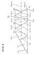
- Fig. 2 illustrates a diagram for explaining interactions between an excitation light and a terahertz wave.
- FIG. 1 A terahertz wave generating apparatus related to the present invention will be explained in accordance with a drawing in Fig. 1 .
- the drawing of Fig. 1 illustrates a configuration of the terahertz wave generating apparatus of an embodiment.
- the terahertz wave generating apparatus in the embodiment is mounted to an imaging examination apparatus or the like which uses terahertz waves.
- Fig. 1 illustrates a terahertz wave generating apparatus 10 in the embodiment including an excitation light source 11, a nonlinear optical crystal 12 and optical systems 17 and 18.
- the excitation light source 11 is a semiconductor laser equipment serving as a light source for emitting an excitation light 13 serving as a toward the nonlinear optical crystal 12 serving as an optical crystal.
- the excitation light 13 is set at 780 nm of its wavelength, and a polarization direction of the excitation light 13 is set so as to be parallel to an axis Z in Fig. 1 .
- the nonlinear optical crystal 12 generates terahertz waves by process of an optical parametric generation on the basis of a nonlinear optical principle for an incident light such as a laser light.
- LN (LiNbO 3 : lithium niobate) crystal is used as the nonlinear optical crystal 12, and an optic axis of the nonlinear optical crystal 12 is in parallel with the axis Z in Fig. 1 .
- the nonlinear optical crystal 12 is formed in a plate shape (e.g., plate like body) whose thickness is "d" ( ⁇ m).
- the thickness "d” is set so as to fulfill a condition where the terahertz wave 15 propagates within the nonlinear optical crystal 12 in a single mode and fulfill a phase matching condition for the optical parametric amplification between the excitation light 13 and the terahertz wave 15.
- the thickness "d" of the nonlinear optical crystal 12 in the embodiment is set to 100 ⁇ m.
- the nonlinear optical crystal 12, serving as a core, and air 16, serving as a clad configure an optical waveguide.
- the optical system 17 is an optical system such as a lens provided between the excitation light source 11 and the nonlinear optical crystal 12.
- the optical system 17 is illustrated in the diagram of Fig. 1 in a simplified manner, however, another optical system may be used in stead of the optical system 17 depending on the configuration of the terahertz wave generating apparatus or an examination apparatus to which the terahertz wave generating apparatus is mounted.
- terahertz wave generating apparatus 10 Only main components of the terahertz wave generating apparatus 10 are explained above and illustrated in the diagram in Fig. 1 for the sake of convenience, however, other parts such as a casing may be provided at the terahertz wave generating apparatus 10.
- the excitation light 13 entering the nonlinear optical crystal 12 generates an idler wave 14 and a terahertz wave 15 by process of optical parametric generation.
- the excitation light 13 is total-reflected on the total reflection planes 12a and 12b, each of which configures principle surfaces of the nonlinear optical crystal 12.
- a refractive index of LN crystal used for the nonlinear optical crystal 12 is set to 2.15, and a refractive index of the air is 1.0003
- the optical waveguide fulfills a condition of the total reflection of the excitation light 13 at an angle ⁇ of 30°. Accordingly, the excitation light 13 propagates within the nonlinear optical crystal 12 by repeating several times the total reflections on the total reflection planes 12a and 12b at the incident angle ⁇ of 30°.
- the terahertz wave 15 propagates within the nonlinear optical crystal 12 at a single mode in a direction indicated by an arrow illustrated in the diagram in Fig. 1 .
- the excitation light 13-1 After entering the nonlinear optical crystal 12 through the incident plane 12c and generating the terahertz wave 15 and the idler wave 14, the excitation light 13-1 propagates toward the total reflection plane 12a after being total-reflected on the total reflection plane 12b.
- the terahertz wave 15 generated within the nonlinear optical crystal 12 is propagated in the direction indicated by an arrow in Fig. 2 .
- the excitation light 13-1 and the terahertz wave 15-1 form an equilateral triangle, and because the propagation speed of the terahertz wave 15 within the nonlinear optical crystal 12 is half of the propagation speed of the excitation light 13 within the nonlinear optical crystal 12, the excitation light 13-1 and the terahertz wave 15-1 reach the point S1 at the same time.
- the intensity of the excitation light 13-1 is reduced by the amplification of the terahertz wave 15-1 so as to be the excitation light 13-2, whose intensity is lower than that of the excitation light 13-1, and the excitation light 13-2 is further propagated within the nonlinear optical crystal 12.
- the excitation light 13-2 total-reflected on the total reflection plane 12a and the terahertz wave 15-2 interact with each other at the point S2 repetitively, so that the terahertz wave 15-2 is amplified to be the terahertz wave 15-3, and the intensity of the excitation light 13-2 is reduced so as to be an excitation light 13-3 whose intensity is lower than that of the excitation light 13-2.
- the terahertz wave 15 After “n” times of the interaction (at the point Sn), the terahertz wave 15 has been amplified by the excitation light 13 "n” times so as to be the terahertz wave 15out, whose intensity is relatively highest, and the terahertz wave 15out exits the nonlinear optical crystal 12 through the exit plane 12d.
- An object to be examined is irradiated with the outputted terahertz wave 15out in order to obtain, for example image information of the object, by means of a detecting means of the examination apparatus.
- the intensity of the excitation light 13 has been reduced so as to be the excitation light 13out, whose intensity is relatively the lowest, and exits the nonlinear optical crystal 12 through the exit plane 12d.
- the outputted excitation light 13out and the idler wave 14 are absorbed by an absorving apparatus or the like.
Landscapes
- Physics & Mathematics (AREA)
- Nonlinear Science (AREA)
- General Physics & Mathematics (AREA)
- Optics & Photonics (AREA)
- Optical Modulation, Optical Deflection, Nonlinear Optics, Optical Demodulation, Optical Logic Elements (AREA)
Abstract
Description
- The present invention relates to a terahertz wave generating apparatus and a terahertz wave generating method for generating high-intensified terahertz waves.
- Terahertz waves are electromagnetic waves having frequency in a range between 0.1 and 10THz and having wavelength in a range between 30 and 3000µm, which approximately correspond to a range between a microwave band and a light. Taking advantage of this characteristic, the terahertz wave has been expected to be applied to various areas such as telecommunication, examination and the like.
- A device and a method for generating terahertz waves are disclosed in a non-patent document 1: Kiyomi Sakai "terahertz time-domain spectroscopy (THz-TDS)", spectroscopy kenkyu, Vol, 50, No. 6, 2001, p.261-273, and a non-patent document 2: Hoffman et al., "Efficient terahertz generation by optical rectification at 1035 nm", OPTICS EXPRESS, Vol. 15, No. 18, 3 September 2007, pp.11706-11713.
- In the
non-patent document 1, several technologies for generating terahertz waves are disclosed. As one example, a terahertz wave is generated by use of an antenna element such as a voltage- biased antenna having a micro antenna structure. Specifically, the terahertz wave is generated by using the antenna irradiated with an ultra short pulse laser. As another example, a terahertz wave is generated on the basis of a nonlinear effect. Specifically, the terahertz wave is generated on the basis of light rectification effect by using a certain material having a reversal symmetry χ(2) irradiated with ultra short pulse laser. Furthermore, a surface semiconductor and an application of magnetic field are used in order to generate the terahertz wave. - In the
non-patent document 2, a technology for generating high-intensified terahertz waves, on the basis of the Cherenkov radiation theory, within LN(LiNbO3 : lithium niobate) crystal, in such a way that wavefront of an incident laser is tilted by use of diffraction grating, is disclosed. - According to the
non-patent document 1, because the intensity of the obtained terahertz wave (output) is relatively low, such terahertz wave may not be used for areas other than spectroscopic measurement. - Further, according to the
non-patent document 2, because the wavefront of the incident laser needs to be tilted, an optical system for propagating a beam image focused on the diffraction grating, by use of the diffraction grating and a lens, is used. In this configuration, the light tilted at the diffraction grating may be dispersed at areas other than the vicinity of the focal point of the lens, accordingly, a positional alignment of the optical system needs to be adjusted very precisely. - A need thus exists for a terahertz wave generating apparatus and a terahertz wave generating method by which a high-intensified terahertz wave is generated by a simple structure.
- According to an aspect of the present invention, a terahertz wave generating apparatus includes an excitation light source for outputting an excitation light at a predetermined wavelength, an optical crystal being excited by an irradiation with the excitation light in order to generate a terahertz wave and terahertz wave amplifying means for repeatedly performing an optical parametric amplification for the terahertz wave by use of the excitation light, wherein the terahertz wave amplifying means includes an optical waveguide having the optical crystal serving as a core and a medium serving as a clad whose refractive index is smaller than a refractive index of the optical crystal, and the inputted excitation light is propagated within the optical waveguide with fulfilling a condition for a total reflection.
- According to another aspect of the present invention, the optical crystal is formed in a plate shape body having a predetermined thickness and having first and second principle surfaces formed so as to be parallel to each other and a tapered surface, a predetermined angle is set between each of the first and second principle surfaces and the tapered surface, the excitation light vertically enters the optical crystal through the tapered surface, the clad including a layer of the medium having a predetermined refractive index is arranged so as to contact at least one of the first and second principle surfaces of the optical crystal, the terahertz wave amplifying means is structured so as to perform a total reflection on an interfacial surface between the first principle surface and the clad and on an interfacial surface between the second principle surface and the clad, and the predetermined thickness of the optical crystal is set so as to fulfill a phase matching condition of the optical parametric amplification between the excitation light and the terahertz wave propagated within the optical crystal and so as to fulfill a condition where a propagation mode of the terahertz wave is in a single mode.
- According to further aspect of the present invention, the optical crystal is a LiNbO3 crystal.
- According to yet further aspect of the present invention, a terahertz wave generating method includes steps of; outputting an excitation light toward an optical crystal at a predetermined wavelength, generating a terahertz wave by exciting the optical crystal and propagating the inputted excitation light with performing a total reflection within the optical waveguide having the optical crystal as a core, and repeatedly performing an optical parametric amplification for the terahertz wave by use of the excitation light,
- The foregoing and additional features and characteristics of the present invention will become more apparent from the following detailed description considered with the reference to the accompanying drawings, wherein:
-
Fig. 1 illustrates a configuration diagram of a terahertz wave generating apparatus of an embodiment related to the present invention; and -
Fig. 2 illustrates a diagram for explaining interactions between an excitation light and a terahertz wave. - A terahertz wave generating apparatus related to the present invention will be explained in accordance with a drawing in
Fig. 1 . The drawing ofFig. 1 illustrates a configuration of the terahertz wave generating apparatus of an embodiment. The terahertz wave generating apparatus in the embodiment is mounted to an imaging examination apparatus or the like which uses terahertz waves. -
Fig. 1 illustrates a terahertzwave generating apparatus 10 in the embodiment including anexcitation light source 11, a nonlinearoptical crystal 12 andoptical systems - The
excitation light source 11 is a semiconductor laser equipment serving as a light source for emitting anexcitation light 13 serving as a toward the nonlinearoptical crystal 12 serving as an optical crystal. In the embodiment, theexcitation light 13 is set at 780 nm of its wavelength, and a polarization direction of theexcitation light 13 is set so as to be parallel to an axis Z inFig. 1 . - The nonlinear
optical crystal 12 generates terahertz waves by process of an optical parametric generation on the basis of a nonlinear optical principle for an incident light such as a laser light. In the embodiment, LN (LiNbO3 : lithium niobate) crystal is used as the nonlinearoptical crystal 12, and an optic axis of the nonlinearoptical crystal 12 is in parallel with the axis Z inFig. 1 . - As illustrated in
Fig. 1 , the nonlinearoptical crystal 12 is formed in a plate shape (e.g., plate like body) whose thickness is "d" (µm). The thickness "d" is set so as to fulfill a condition where theterahertz wave 15 propagates within the nonlinearoptical crystal 12 in a single mode and fulfill a phase matching condition for the optical parametric amplification between theexcitation light 13 and theterahertz wave 15. The thickness "d" of the nonlinearoptical crystal 12 in the embodiment is set to 100µm. - The nonlinear
optical crystal 12 includes anincident plane 12c (e.g., a tapered surface) through which the excitation right 13 enters the nonlinearoptical crystal 12. Theincident plane 12c is formed so as to form an angle θ between theincident plane 12c and principle surfaces (total reflection planes 12a and 12b formed parallel to each other) of the nonlinearoptical crystal 12. The angle θ is set so as to fulfill a condition where theexcitation light 13 is total-reflected on thetotal reflection planes 12a and 12b. In the embodiment, the angle θ is set to 30°, and anexit plane 12d through which theexcitation light 13 and theterahertz wave 15 exit the nonlinearoptical crystal 12 is formed so as to be vertical relative to each of thetotal reflection planes 12a and 12b. - Because the wavelength of the
excitation light 13 is different from that of theterahertz wave 15, theexcitation light 13 and theterahertz wave 15 propagate within the nonlinearoptical crystal 12 at different speeds. In the embodiment, the propagation speed of theterahertz wave 15 is set so as to be a half of the propagation speed of theexcitation light 13, - In this configuration, the nonlinear
optical crystal 12, serving as a core, andair 16, serving as a clad, configure an optical waveguide. - The
optical system 17 is an optical system such as a lens provided between theexcitation light source 11 and the nonlinearoptical crystal 12. Theoptical system 17 is illustrated in the diagram ofFig. 1 in a simplified manner, however, another optical system may be used in stead of theoptical system 17 depending on the configuration of the terahertz wave generating apparatus or an examination apparatus to which the terahertz wave generating apparatus is mounted. - Only main components of the terahertz
wave generating apparatus 10 are explained above and illustrated in the diagram inFig. 1 for the sake of convenience, however, other parts such as a casing may be provided at the terahertzwave generating apparatus 10. - An actuation of the terahertz
wave generating apparatus 10 structured as mentioned above will be explained. - As illustrated in the drawing in
Fig. 1 , when theexcitation light source 11 emits theexcitation light 13 toward theincident plane 12c of the nonlinearoptical crystal 12, theexcitation light 13 vertically enters the nonlinearoptical crystal 12 through theincident plane 12c. - The
excitation light 13 entering the nonlinearoptical crystal 12 generates anidler wave 14 and aterahertz wave 15 by process of optical parametric generation. On the basis of law of conservation of energy, a relation among an angular frequency of the excitation light 13 (ω1), an angular frequency of the idler wave 14 (ω2) and an angular frequency of the terahertz wave 15 (ω3) is expressed by a formula: ω1=ω2+ω3. Further, on the basis of law of conservation of momentum, a relation among a light vector of the excitation light 13 (k1), a light vector of the idler wave 14 (k2) and a light vector of the terahertz wave 15 (k3) is expressed by a formula: k1=k2+k3. - Then, the
excitation light 13 is total-reflected on thetotal reflection planes 12a and 12b, each of which configures principle surfaces of the nonlinearoptical crystal 12. Because a refractive index of LN crystal used for the nonlinearoptical crystal 12 is set to 2.15, and a refractive index of the air is 1.0003, the optical waveguide fulfills a condition of the total reflection of theexcitation light 13 at an angle θ of 30°. Accordingly, theexcitation light 13 propagates within the nonlinearoptical crystal 12 by repeating several times the total reflections on thetotal reflection planes 12a and 12b at the incident angle θ of 30°. - The
terahertz wave 15 propagates within the nonlinearoptical crystal 12 at a single mode in a direction indicated by an arrow illustrated in the diagram inFig. 1 . - A relationship between the
excitation light 13 and theterahertz wave 15 will be explained in detail in accordance with the drawing ofFig. 2 . InFig. 2 , theexcitation light 13 is indicated by numerals of 13-1,13-2,···, 13-n (n=positive integer) and 13out in its propagation order, and theterahertz wave 15 is indicated by numerals of 15-1,15-2,···, 15-n (n=posiflve integer) and 15out in its propagation order, Points S1, S2 and Sn (n=positive integer) each indicates an imaginary point at which theexcitation light 13 and theterahertz wave 15 interact with each other. - After entering the nonlinear
optical crystal 12 through theincident plane 12c and generating theterahertz wave 15 and theidler wave 14, the excitation light 13-1 propagates toward the total reflection plane 12a after being total-reflected on thetotal reflection plane 12b. Theterahertz wave 15 generated within the nonlinearoptical crystal 12 is propagated in the direction indicated by an arrow inFig. 2 . - As indicated in the drawing of
Fig. 2 , because the excitation light 13-1 and the terahertz wave 15-1 form an equilateral triangle, and because the propagation speed of theterahertz wave 15 within the nonlinearoptical crystal 12 is half of the propagation speed of theexcitation light 13 within the nonlinearoptical crystal 12, the excitation light 13-1 and the terahertz wave 15-1 reach the point S1 at the same time. - Then, an interaction between the excitation light 13-1 and the terahertz wave 15-1 occurs at the point S1. A phase matching condition of the optical parametric amplification between the
excitation light 13 and theterahertz wave 15 is fulfilled in this interaction. Accordingly, the terahertz wave 15-1 is optical-parametrically amplified to be the terahertz wave 15-2, which has an intensity that is higher than the intensity of the terahertz wave 15-1, and the amplified terahertz wave 15-2 is further propagated within the nonlinearoptical crystal 12. On the other hand, the intensity of the excitation light 13-1 is reduced by the amplification of the terahertz wave 15-1 so as to be the excitation light 13-2, whose intensity is lower than that of the excitation light 13-1, and the excitation light 13-2 is further propagated within the nonlinearoptical crystal 12. - The excitation light 13-2 total-reflected on the total reflection plane 12a and the terahertz wave 15-2 interact with each other at the point S2 repetitively, so that the terahertz wave 15-2 is amplified to be the terahertz wave 15-3, and the intensity of the excitation light 13-2 is reduced so as to be an excitation light 13-3 whose intensity is lower than that of the excitation light 13-2.
- After "n" times of the interaction (at the point Sn), the
terahertz wave 15 has been amplified by theexcitation light 13 "n" times so as to be the terahertz wave 15out, whose intensity is relatively highest, and the terahertz wave 15out exits the nonlinearoptical crystal 12 through theexit plane 12d. An object to be examined is irradiated with the outputted terahertz wave 15out in order to obtain, for example image information of the object, by means of a detecting means of the examination apparatus. - The intensity of the
excitation light 13 has been reduced so as to be the excitation light 13out, whose intensity is relatively the lowest, and exits the nonlinearoptical crystal 12 through theexit plane 12d. The outputted excitation light 13out and theidler wave 14 are absorbed by an absorving apparatus or the like. - Because the positive integer "n" is increased in accordance with the size of the nonlinear
optical crystal 12 in a propagation direction, the intensity of theterahertz wave 15 may be appropriately increased depending on the size of the nonlinearoptical crystal 12 by means of the interaction between theterahertz wave 15 and theexcitation light 13. However, because the intensity of theexcitation light 13 is reduced by repeating the amplification of theterahertz wave 15, theexcitation light 13 is fogged as the propagation thereof proceeds. Therefore, the size of the nonlinearoptical crystal 12 in the propagation direction may be set appropriately in consideration with the intensity of theexcitation light 13 entering the nonlinearoptical crystal 12. - In the embodiment, the total reflection of the excitation light is repeated within the nonlinear
optical crystal 12, which configures the optical waveguide, at the same time, the terahertz wave generated within the nonlinear optical crystal by process of the optical parametric generation interacts with the excitation light so as to fulfill the phase matching condition of the optical parametric amplification. Accordingly, using a single excitation light, the terahertz wave may be parametrically amplified several times, in other words, a terahertz wave with high intensity may be generated by a device whose configuration is relatively simple. - The terahertz wave generating apparatus and method in the embodiment may be modified or may be applied to another apparatus'.
- For example, in the embodiment, the angle θ indicated in the drawing of
Fig. 1 is set to 30°, however, the angle θ may be modified as long as a condition where theexcitation light 13 is total-reflected is fulfilled, and a condition where the phase matching condition between theexcitation light 13 and theterahertz wave 15 is also fulfilled. Further, types of theexcitation light 13 and the nonlinearoptical crystal 12 may be changed in the same manner as the angle θ. - Further, in the embodiment, the optical waveguide is comprised of the nonlinear
optical crystal 12 serving as a core and theair 16 serving as clad, however, the medium may be changed, regardless of vapor or solid substance, as long as it fulfills the condition for the total reflection of theexcitation light 13. - In the embodiment, the terahertz
wave generating apparatus 10 is mounted to an imaging examination apparatus, however, the device may be applied to another apparatus such as a spectroscopic measurement apparatus, a telecommunication apparatus, a chemical analysis apparatus and the like. - As described in the embodiment, a terahertz wave generating apparatus includes an excitation light source for outputting an excitation light at a predetermined wavelength, an optical crystal being excited by an irradiation with the excitation light in order to generate a terahertz wave and terahertz wave amplifying means for repeatedly performing an optical parametric amplification for the terahertz wave by use of the excitation light, wherein the terahertz wave amplifying means includes an optical waveguide having the optical crystal serving as a core and a medium serving as a clad whose refractive index is smaller than a refractive index of the optical crystal, and the inputted excitation light is propagated within the optical waveguide with fulfilling a condition for a total reflection.
- Further, the optical crystal is formed in a plate shape body having a predetermined thickness and having first and second principle surfaces formed so as to be parallel to each other and a tapered surface, a predetermined angle is set between each of the first and second principle surfaces and the tapered surface, the excitation light vertically enters the optical crystal through the tapered surface, the clad including a layer of the medium having a predetermined refractive index is arranged so as to contact at least one of the first and second principle surfaces of the optical crystal, the terahertz wave amplifying means is structured so as to perform a total reflection on an interfacial surface between the first principle surface and the clad and on an interfacial surface between the second principle surface and the clad, and the predetermined thickness of the optical crystal is set so as to fulfill a phase matching condition of the optical parametric amplification between the excitation light and the terahertz wave propagated within the optical crystal and so as to fulfill a condition where a propagation mode of the terahertz wave is in a single mode.
- Furthermore, the optical crystal is a LiNbO3 crystal, and a terahertz wave generating method includes steps of; outputting an excitation light toward an optical crystal at a predetermined wavelength, generating a terahertz wave by exciting the optical crystal and propagating the inputted excitation light with performing a total reflection within the optical waveguide having the optical crystal as a core, and repeatedly performing an optical parametric amplification for the terahertz wave by use of the excitation light.
- Thus, high-intensified terahertz waves are generated by repeatedly performing the optical parametric amplification of the terahertz waves, generated by use of the optical crystal excited by the irradiation with the excitation light, by use of the excitation light propagating with performing the total reflection within the optical waveguide including the optical crystal serving as a core.
A terahertz wave generating apparatus includes an excitation light source (11) for outputting an excitation light (13) at a predetermined wavelength, an optical crystal (12) being excited by an irradiation with the excitation light (13) in order to generate a terahertz wave (15) and terahertz wave amplifying means for repeatedly performing an optical parametric amplification for the terahertz wave (15) by use of the excitation light (13), wherein the terahertz wave amplifying means includes an optical waveguide having the optical crystal (12) serving as a core and a medium serving as a clad whose refractive index is smaller than a refractive index of the optical crystal (12), and the inputted excitation light (13) is propagated within the optical waveguide with fulfilling a condition for a total reflection.
Claims (4)
- A terahertz wave generating apparatus comprising:an excitation light source (11) for outputting an excitation light (13) at a predetermined wavelength;an optical crystal (12) being excited by an irradiation with the excitation light (13) in order to generate a terahertz wave (15); andterahertz wave amplifying means for repeatedly performing an optical parametric amplification for the terahertz wave (15) by use of the excitation light (13);wherein
the terahertz wave amplifying means includes an optical waveguide having the optical crystal (12) serving as a core and a medium serving as a clad whose refractive index is smaller than a refractive index of the optical crystal (12), and the inputted excitation light (13) is propagated within the optical waveguide with fulfilling a condition for a total reflection. - The terahertz wave generating apparatus according to Claim 1, wherein the optical crystal (12) is formed in a plate shape body having a predetermined thickness and having first and second principle surfaces (12a, 12b) formed so as to be parallel to each other and a tapered surface (12c), a predetermined angle is set between each of the first and second principle surfaces (12a, 12b) and the tapered surface (12c), the excitation light (13) vertically enters the optical crystal (12) through the tapered surface (12c), the clad (16) including a layer of the medium having a predetermined refractive index is arranged so as to contact at least one of the first and second principle surfaces (12a, 12b) of the optical crystal (12), the terahertz wave amplifying means is structured so as to perform a total reflection on an interfacial surface between the first principle surface (12a) and the clad (16) and on an interfacial surface between the second principle surface (12b) and the clad (16), and the predetermined thickness of the optical crystal (12) is set so as to fulfill a phase matching condition of the optical parametric amplification between the excitation light (13) and the terahertz wave (15) propagated within the optical crystal (12) and so as to fulfill a condition where a propagation mode of the terahertz wave (15) is in a single mode.
- The terahertz wave generating apparatus according to Claims 1 or 2, wherein the optical crystal (12) is a LiNbO3 crystal.
- A terahertz wave generating method comprising steps of:outputting an excitation light (13) toward an optical crystal (12) at a predetermined wavelength;generating a terahertz wave (15) by exciting the optical crystal (12); andpropagating the inputted excitation light (13) with performing a total reflection within the optical waveguide having the optical crystal (12) as a core, and repeatedly performing an optical parametric amplification for the terahertz wave (15) by use of the excitation light (13), outputting an excitation light.
Applications Claiming Priority (1)
| Application Number | Priority Date | Filing Date | Title |
|---|---|---|---|
| JP2008217050A JP5098895B2 (en) | 2008-08-26 | 2008-08-26 | Terahertz wave generation apparatus and terahertz wave generation method |
Publications (2)
| Publication Number | Publication Date |
|---|---|
| EP2159634A1 true EP2159634A1 (en) | 2010-03-03 |
| EP2159634B1 EP2159634B1 (en) | 2011-08-24 |
Family
ID=41057782
Family Applications (1)
| Application Number | Title | Priority Date | Filing Date |
|---|---|---|---|
| EP09168594A Not-in-force EP2159634B1 (en) | 2008-08-26 | 2009-08-25 | Terahertz-wave optical generating apparatus |
Country Status (4)
| Country | Link |
|---|---|
| US (1) | US20100054296A1 (en) |
| EP (1) | EP2159634B1 (en) |
| JP (1) | JP5098895B2 (en) |
| AT (1) | ATE521914T1 (en) |
Families Citing this family (8)
| Publication number | Priority date | Publication date | Assignee | Title |
|---|---|---|---|---|
| JP5419411B2 (en) * | 2008-10-08 | 2014-02-19 | キヤノン株式会社 | Terahertz wave generator |
| JP5555042B2 (en) * | 2010-04-22 | 2014-07-23 | 浜松ホトニクス株式会社 | Terahertz wave generator |
| HU229943B1 (en) * | 2010-09-22 | 2015-01-28 | Pecsi Tudomanyegyetem | Optical excited thz radiation source based on rectification |
| US9040919B2 (en) * | 2010-10-25 | 2015-05-26 | Thomas E. Darcie | Photomixer-waveguide coupling tapers |
| WO2013046842A1 (en) * | 2011-09-28 | 2013-04-04 | 株式会社アドバンテスト | Electromagnetic wave detector device |
| CN104037595B (en) * | 2014-06-20 | 2017-05-24 | 华北水利水电大学 | Terahertz wave amplifier based on optical parametric effect |
| US9742145B1 (en) * | 2016-12-01 | 2017-08-22 | National Tsing Hua University | Off-axis zigzag parametric oscillator |
| US11474414B2 (en) * | 2018-10-31 | 2022-10-18 | Pécsi Tudományegyetem | Reflection and/or diffraction-based method and setup to generate high-energy terahertz pulses |
Citations (2)
| Publication number | Priority date | Publication date | Assignee | Title |
|---|---|---|---|---|
| US5640480A (en) | 1995-08-07 | 1997-06-17 | Northrop Grumman Corporation | Zig-zag quasi-phase-matched wavelength converter apparatus |
| EP1717634A1 (en) | 2005-04-25 | 2006-11-02 | ONERA (Office National d'Etudes et de Recherches Aérospatiales) | Wave generation by compensation of propagation phase-lag in a nonlinear optical medium |
Family Cites Families (7)
| Publication number | Priority date | Publication date | Assignee | Title |
|---|---|---|---|---|
| US3983406A (en) * | 1975-06-16 | 1976-09-28 | Massachusetts Institute Of Technology | Method of and apparatus for generating tunable coherent radiation by nonlinear light mixing in systems having folded noncollinear geometries |
| GB2343964B (en) * | 1998-11-03 | 2000-11-01 | Toshiba Res Europ Ltd | An optical device |
| JP3266194B2 (en) * | 1999-02-18 | 2002-03-18 | 日本電気株式会社 | Optical waveguide and laser oscillator and laser amplifier using the optical waveguide |
| US20020171913A1 (en) * | 2000-11-16 | 2002-11-21 | Lightbit Corporation | Method and apparatus for acheiving |
| JP4609993B2 (en) * | 2004-12-08 | 2011-01-12 | 独立行政法人理化学研究所 | Terahertz wave generation method and apparatus |
| JP4354932B2 (en) * | 2005-06-07 | 2009-10-28 | 独立行政法人科学技術振興機構 | Terahertz light source |
| JP2009180809A (en) * | 2008-01-29 | 2009-08-13 | Sekisui Chem Co Ltd | Terahertz electromagnetic wave generator |
-
2008
- 2008-08-26 JP JP2008217050A patent/JP5098895B2/en not_active Expired - Fee Related
-
2009
- 2009-08-24 US US12/546,236 patent/US20100054296A1/en not_active Abandoned
- 2009-08-25 EP EP09168594A patent/EP2159634B1/en not_active Not-in-force
- 2009-08-25 AT AT09168594T patent/ATE521914T1/en not_active IP Right Cessation
Patent Citations (2)
| Publication number | Priority date | Publication date | Assignee | Title |
|---|---|---|---|---|
| US5640480A (en) | 1995-08-07 | 1997-06-17 | Northrop Grumman Corporation | Zig-zag quasi-phase-matched wavelength converter apparatus |
| EP1717634A1 (en) | 2005-04-25 | 2006-11-02 | ONERA (Office National d'Etudes et de Recherches Aérospatiales) | Wave generation by compensation of propagation phase-lag in a nonlinear optical medium |
Non-Patent Citations (10)
| Title |
|---|
| KOMINE H ET AL.: "OPTICS LETTERS", vol. 23, 1 May 1998, OPTICAL SOCIETY OF AMERICA, article "Quasi-phase-matched second-harmonic generation by use of a total- internal-reflection phase shift in gallium arsenide and zinc selenide plates", pages: 661 - 663 |
| KOMINE H ET AL: "QUASI-PHASE-MATCHED SECOND-HARMONIC GENERATION BY USE OF A TOTAL- INTERNAL-REFLECTION PHASE SHIFT IN GALLIUM ARSENIDE AND ZINC SELENIDE PLATES", OPTICS LETTERS, OSA, OPTICAL SOCIETY OF AMERICA, WASHINGTON, DC, US, vol. 23, no. 9, 1 May 1998 (1998-05-01), pages 661 - 663, XP000755365, ISSN: 0146-9592 * |
| L'HUILLIER J A ET AL.: "Generation of THz radiation using bulk, periodically and aperiodically poled lithium niobate - Part 2: Experiments", APPLIED PHYSICS B; LASERS AND OPTICS, vol. 86, 13 December 2006 (2006-12-13), pages 197 - 208 |
| L'HUILLIER J A ET AL: "Generation of THz radiation using bulk, periodically and aperiodically poled lithium niobate - Part 2: Experiments", APPLIED PHYSICS B ; LASERS AND OPTICS, SPRINGER, BERLIN, DE, vol. 86, no. 2, 13 December 2006 (2006-12-13), pages 197 - 208, XP019473385, ISSN: 1432-0649 * |
| RAYBAUT M ET AL.: "A guided wave approach to Fresnel Phase Matching: Application to parametric oscillation and terahertz-wave generation", LASERS AND ELECTRO-OPTICS AND 2006 QUANTUM ELECTRONICS AND LASER SCIENCE CONFERENCE. CLEO/QELS 2006. CONFERENCE ON, IEEE, PISCATAWAY, 21 May 2006 (2006-05-21), pages 1 - 2 |
| RAYBAUT M ET AL: "A guided wave approach to Fresnel Phase Matching: Application to parametric oscillation and terahertz-wave generation", LASERS AND ELECTRO-OPTICS AND 2006 QUANTUM ELECTRONICS AND LASER SCIENCE CONFERENCE. CLEO/QELS 2006. CONFERENCE ON, IEEE, PISCATAWAY, NJ, USA, 21 May 2006 (2006-05-21), pages 1 - 2, XP031394479, ISBN: 978-1-55752-813-1 * |
| RAYBAUT MYRIAM ET AL.: "APPLIED PHYSICS LETTERS", vol. 92, 28 March 2008, AMERICAN INSTITUTE OF PHYSICS, article "Nonlinear reflection effects on Fresnel phase matching", pages: 121112 - 121112 |
| RAYBAUT MYRIAM ET AL: "Nonlinear reflection effects on Fresnel phase matching", APPLIED PHYSICS LETTERS, AIP, AMERICAN INSTITUTE OF PHYSICS, MELVILLE, NY, US, vol. 92, no. 12, 28 March 2008 (2008-03-28), pages 121112 - 121112, XP012106104, ISSN: 0003-6951 * |
| SERKLAND D ET AL.: "CW optical parametric oscillation near 2.1 um, pumped by 1064 nm", LASERS AND ELECTRO-OPTICS SOCIETY ANNUAL MEETING, 1993. LEOS '93 CONFERENCE PROCEEDINGS, 15 November 1993 (1993-11-15), pages 105 - 106 |
| SERKLAND D ET AL: "CW optical parametric oscillation near 2.1 /spl mu/m, pumped by 1064 nm", LASERS AND ELECTRO-OPTICS SOCIETY ANNUAL MEETING, 1993. LEOS '93 CONFE RENCE PROCEEDINGS. IEEE SAN JOSE, CA, USA 15-18 NOV. 1993, NEW YORK, NY, USA,IEEE, 15 November 1993 (1993-11-15), pages 105 - 106, XP010129277, ISBN: 978-0-7803-1263-0 * |
Also Published As
| Publication number | Publication date |
|---|---|
| JP5098895B2 (en) | 2012-12-12 |
| ATE521914T1 (en) | 2011-09-15 |
| US20100054296A1 (en) | 2010-03-04 |
| EP2159634B1 (en) | 2011-08-24 |
| JP2010054611A (en) | 2010-03-11 |
Similar Documents
| Publication | Publication Date | Title |
|---|---|---|
| EP2159634B1 (en) | Terahertz-wave optical generating apparatus | |
| Tomasino et al. | Wideband THz time domain spectroscopy based on optical rectification and electro-optic sampling | |
| JP5419411B2 (en) | Terahertz wave generator | |
| JP5642405B2 (en) | Terahertz wave generator | |
| CN102998260B (en) | A terahertz wave imaging device based on two-photon entanglement | |
| JP6692103B2 (en) | System and method for high contrast / near real time acquisition of terahertz images | |
| US20160197447A1 (en) | Broadband terahertz generation of metamaterials | |
| CN105737984A (en) | Terahertz time domain spectral radiation and detecting device | |
| Wang et al. | Enhanced on-chip terahertz sensing with hybrid metasurface/lithium niobate structures | |
| JP6779937B2 (en) | Terahertz wave generator and terahertz time region spectrometer | |
| CN103097952B (en) | Electromagnetic THz wave generating device, electromagnetic THz wave detecting device and time domain spectroscopic device | |
| US20150136987A1 (en) | Terahertz wave generator, terahertz wave detector, and terahertz time domain spectroscopy device | |
| JP5527570B2 (en) | Terahertz light source | |
| US8759779B2 (en) | Terahertz wave generation element, terahertz wave detection element, and terahertz time domain spectral device | |
| Chen et al. | Continuously tunable and energy-enhanced injection pulse-seeded terahertz parametric generator based on KTP crystal | |
| US20160377958A1 (en) | Terahertz wave generating apparatus and information obtaining apparatus | |
| CN104037595B (en) | Terahertz wave amplifier based on optical parametric effect | |
| JP2009180809A (en) | Terahertz electromagnetic wave generator | |
| JP2010139604A (en) | Electromagnetic wave generation/transmission apparatus | |
| JP4838111B2 (en) | Electromagnetic wave detector and electromagnetic wave detection system | |
| Smith et al. | THz field enhancement by antenna coupling to a tapered thick slot waveguide | |
| Schulz et al. | Integrated nonlinear waveguide optics for high-efficiency and wideband-tunable generation of THz radiation | |
| US9846348B2 (en) | Photon energy conversion by near-zero permittivity nonlinear materials | |
| JP2014081345A (en) | Sensor | |
| US20040262544A1 (en) | Semiconductor surface-field emitter for T-ray generation |
Legal Events
| Date | Code | Title | Description |
|---|---|---|---|
| PUAI | Public reference made under article 153(3) epc to a published international application that has entered the european phase |
Free format text: ORIGINAL CODE: 0009012 |
|
| AK | Designated contracting states |
Kind code of ref document: A1 Designated state(s): AT BE BG CH CY CZ DE DK EE ES FI FR GB GR HR HU IE IS IT LI LT LU LV MC MK MT NL NO PL PT RO SE SI SK SM TR |
|
| AX | Request for extension of the european patent |
Extension state: AL BA RS |
|
| 17P | Request for examination filed |
Effective date: 20100902 |
|
| 17Q | First examination report despatched |
Effective date: 20101013 |
|
| GRAP | Despatch of communication of intention to grant a patent |
Free format text: ORIGINAL CODE: EPIDOSNIGR1 |
|
| RTI1 | Title (correction) |
Free format text: TERAHERTZ-WAVE OPTICAL GENERATING APPARATUS |
|
| RIN1 | Information on inventor provided before grant (corrected) |
Inventor name: UEHARA, YUZURU Inventor name: OHTAKE, HIDEYUKI Inventor name: NAGAI, MASAYA Inventor name: TANAKA, KOICHIRO Inventor name: ICHIKAWA, YUKI |
|
| GRAS | Grant fee paid |
Free format text: ORIGINAL CODE: EPIDOSNIGR3 |
|
| GRAA | (expected) grant |
Free format text: ORIGINAL CODE: 0009210 |
|
| AK | Designated contracting states |
Kind code of ref document: B1 Designated state(s): AT BE BG CH CY CZ DE DK EE ES FI FR GB GR HR HU IE IS IT LI LT LU LV MC MK MT NL NO PL PT RO SE SI SK SM TR |
|
| REG | Reference to a national code |
Ref country code: GB Ref legal event code: FG4D |
|
| REG | Reference to a national code |
Ref country code: CH Ref legal event code: EP |
|
| REG | Reference to a national code |
Ref country code: IE Ref legal event code: FG4D |
|
| REG | Reference to a national code |
Ref country code: DE Ref legal event code: R096 Ref document number: 602009002247 Country of ref document: DE Effective date: 20111020 |
|
| REG | Reference to a national code |
Ref country code: NL Ref legal event code: VDEP Effective date: 20110824 |
|
| PG25 | Lapsed in a contracting state [announced via postgrant information from national office to epo] |
Ref country code: MT Free format text: LAPSE BECAUSE OF FAILURE TO SUBMIT A TRANSLATION OF THE DESCRIPTION OR TO PAY THE FEE WITHIN THE PRESCRIBED TIME-LIMIT Effective date: 20110824 |
|
| LTIE | Lt: invalidation of european patent or patent extension |
Effective date: 20110824 |
|
| PG25 | Lapsed in a contracting state [announced via postgrant information from national office to epo] |
Ref country code: NO Free format text: LAPSE BECAUSE OF FAILURE TO SUBMIT A TRANSLATION OF THE DESCRIPTION OR TO PAY THE FEE WITHIN THE PRESCRIBED TIME-LIMIT Effective date: 20111124 Ref country code: FI Free format text: LAPSE BECAUSE OF FAILURE TO SUBMIT A TRANSLATION OF THE DESCRIPTION OR TO PAY THE FEE WITHIN THE PRESCRIBED TIME-LIMIT Effective date: 20110824 Ref country code: IS Free format text: LAPSE BECAUSE OF FAILURE TO SUBMIT A TRANSLATION OF THE DESCRIPTION OR TO PAY THE FEE WITHIN THE PRESCRIBED TIME-LIMIT Effective date: 20111224 Ref country code: HR Free format text: LAPSE BECAUSE OF FAILURE TO SUBMIT A TRANSLATION OF THE DESCRIPTION OR TO PAY THE FEE WITHIN THE PRESCRIBED TIME-LIMIT Effective date: 20110824 Ref country code: PT Free format text: LAPSE BECAUSE OF FAILURE TO SUBMIT A TRANSLATION OF THE DESCRIPTION OR TO PAY THE FEE WITHIN THE PRESCRIBED TIME-LIMIT Effective date: 20111226 Ref country code: SE Free format text: LAPSE BECAUSE OF FAILURE TO SUBMIT A TRANSLATION OF THE DESCRIPTION OR TO PAY THE FEE WITHIN THE PRESCRIBED TIME-LIMIT Effective date: 20110824 Ref country code: LT Free format text: LAPSE BECAUSE OF FAILURE TO SUBMIT A TRANSLATION OF THE DESCRIPTION OR TO PAY THE FEE WITHIN THE PRESCRIBED TIME-LIMIT Effective date: 20110824 Ref country code: NL Free format text: LAPSE BECAUSE OF FAILURE TO SUBMIT A TRANSLATION OF THE DESCRIPTION OR TO PAY THE FEE WITHIN THE PRESCRIBED TIME-LIMIT Effective date: 20110824 |
|
| REG | Reference to a national code |
Ref country code: AT Ref legal event code: MK05 Ref document number: 521914 Country of ref document: AT Kind code of ref document: T Effective date: 20110824 |
|
| PG25 | Lapsed in a contracting state [announced via postgrant information from national office to epo] |
Ref country code: GR Free format text: LAPSE BECAUSE OF FAILURE TO SUBMIT A TRANSLATION OF THE DESCRIPTION OR TO PAY THE FEE WITHIN THE PRESCRIBED TIME-LIMIT Effective date: 20111125 Ref country code: LV Free format text: LAPSE BECAUSE OF FAILURE TO SUBMIT A TRANSLATION OF THE DESCRIPTION OR TO PAY THE FEE WITHIN THE PRESCRIBED TIME-LIMIT Effective date: 20110824 Ref country code: PL Free format text: LAPSE BECAUSE OF FAILURE TO SUBMIT A TRANSLATION OF THE DESCRIPTION OR TO PAY THE FEE WITHIN THE PRESCRIBED TIME-LIMIT Effective date: 20110824 Ref country code: AT Free format text: LAPSE BECAUSE OF FAILURE TO SUBMIT A TRANSLATION OF THE DESCRIPTION OR TO PAY THE FEE WITHIN THE PRESCRIBED TIME-LIMIT Effective date: 20110824 Ref country code: CY Free format text: LAPSE BECAUSE OF FAILURE TO SUBMIT A TRANSLATION OF THE DESCRIPTION OR TO PAY THE FEE WITHIN THE PRESCRIBED TIME-LIMIT Effective date: 20110824 Ref country code: SI Free format text: LAPSE BECAUSE OF FAILURE TO SUBMIT A TRANSLATION OF THE DESCRIPTION OR TO PAY THE FEE WITHIN THE PRESCRIBED TIME-LIMIT Effective date: 20110824 |
|
| PG25 | Lapsed in a contracting state [announced via postgrant information from national office to epo] |
Ref country code: MC Free format text: LAPSE BECAUSE OF NON-PAYMENT OF DUE FEES Effective date: 20110831 Ref country code: BE Free format text: LAPSE BECAUSE OF FAILURE TO SUBMIT A TRANSLATION OF THE DESCRIPTION OR TO PAY THE FEE WITHIN THE PRESCRIBED TIME-LIMIT Effective date: 20110824 |
|
| PG25 | Lapsed in a contracting state [announced via postgrant information from national office to epo] |
Ref country code: SK Free format text: LAPSE BECAUSE OF FAILURE TO SUBMIT A TRANSLATION OF THE DESCRIPTION OR TO PAY THE FEE WITHIN THE PRESCRIBED TIME-LIMIT Effective date: 20110824 Ref country code: CZ Free format text: LAPSE BECAUSE OF FAILURE TO SUBMIT A TRANSLATION OF THE DESCRIPTION OR TO PAY THE FEE WITHIN THE PRESCRIBED TIME-LIMIT Effective date: 20110824 |
|
| REG | Reference to a national code |
Ref country code: IE Ref legal event code: MM4A |
|
| PG25 | Lapsed in a contracting state [announced via postgrant information from national office to epo] |
Ref country code: IT Free format text: LAPSE BECAUSE OF FAILURE TO SUBMIT A TRANSLATION OF THE DESCRIPTION OR TO PAY THE FEE WITHIN THE PRESCRIBED TIME-LIMIT Effective date: 20110824 Ref country code: RO Free format text: LAPSE BECAUSE OF FAILURE TO SUBMIT A TRANSLATION OF THE DESCRIPTION OR TO PAY THE FEE WITHIN THE PRESCRIBED TIME-LIMIT Effective date: 20110824 Ref country code: EE Free format text: LAPSE BECAUSE OF FAILURE TO SUBMIT A TRANSLATION OF THE DESCRIPTION OR TO PAY THE FEE WITHIN THE PRESCRIBED TIME-LIMIT Effective date: 20110824 |
|
| PG25 | Lapsed in a contracting state [announced via postgrant information from national office to epo] |
Ref country code: DK Free format text: LAPSE BECAUSE OF FAILURE TO SUBMIT A TRANSLATION OF THE DESCRIPTION OR TO PAY THE FEE WITHIN THE PRESCRIBED TIME-LIMIT Effective date: 20110824 |
|
| PLBE | No opposition filed within time limit |
Free format text: ORIGINAL CODE: 0009261 |
|
| STAA | Information on the status of an ep patent application or granted ep patent |
Free format text: STATUS: NO OPPOSITION FILED WITHIN TIME LIMIT |
|
| PG25 | Lapsed in a contracting state [announced via postgrant information from national office to epo] |
Ref country code: IE Free format text: LAPSE BECAUSE OF NON-PAYMENT OF DUE FEES Effective date: 20110825 |
|
| 26N | No opposition filed |
Effective date: 20120525 |
|
| REG | Reference to a national code |
Ref country code: FR Ref legal event code: ST Effective date: 20120706 |
|
| PG25 | Lapsed in a contracting state [announced via postgrant information from national office to epo] |
Ref country code: FR Free format text: LAPSE BECAUSE OF NON-PAYMENT OF DUE FEES Effective date: 20111024 |
|
| REG | Reference to a national code |
Ref country code: DE Ref legal event code: R097 Ref document number: 602009002247 Country of ref document: DE Effective date: 20120525 |
|
| PG25 | Lapsed in a contracting state [announced via postgrant information from national office to epo] |
Ref country code: MK Free format text: LAPSE BECAUSE OF FAILURE TO SUBMIT A TRANSLATION OF THE DESCRIPTION OR TO PAY THE FEE WITHIN THE PRESCRIBED TIME-LIMIT Effective date: 20110824 |
|
| PG25 | Lapsed in a contracting state [announced via postgrant information from national office to epo] |
Ref country code: SM Free format text: LAPSE BECAUSE OF FAILURE TO SUBMIT A TRANSLATION OF THE DESCRIPTION OR TO PAY THE FEE WITHIN THE PRESCRIBED TIME-LIMIT Effective date: 20110824 Ref country code: ES Free format text: LAPSE BECAUSE OF FAILURE TO SUBMIT A TRANSLATION OF THE DESCRIPTION OR TO PAY THE FEE WITHIN THE PRESCRIBED TIME-LIMIT Effective date: 20111205 |
|
| PG25 | Lapsed in a contracting state [announced via postgrant information from national office to epo] |
Ref country code: LU Free format text: LAPSE BECAUSE OF NON-PAYMENT OF DUE FEES Effective date: 20110825 |
|
| PG25 | Lapsed in a contracting state [announced via postgrant information from national office to epo] |
Ref country code: BG Free format text: LAPSE BECAUSE OF FAILURE TO SUBMIT A TRANSLATION OF THE DESCRIPTION OR TO PAY THE FEE WITHIN THE PRESCRIBED TIME-LIMIT Effective date: 20111124 |
|
| PG25 | Lapsed in a contracting state [announced via postgrant information from national office to epo] |
Ref country code: TR Free format text: LAPSE BECAUSE OF FAILURE TO SUBMIT A TRANSLATION OF THE DESCRIPTION OR TO PAY THE FEE WITHIN THE PRESCRIBED TIME-LIMIT Effective date: 20110824 |
|
| PG25 | Lapsed in a contracting state [announced via postgrant information from national office to epo] |
Ref country code: HU Free format text: LAPSE BECAUSE OF FAILURE TO SUBMIT A TRANSLATION OF THE DESCRIPTION OR TO PAY THE FEE WITHIN THE PRESCRIBED TIME-LIMIT Effective date: 20110824 |
|
| REG | Reference to a national code |
Ref country code: CH Ref legal event code: PL |
|
| PG25 | Lapsed in a contracting state [announced via postgrant information from national office to epo] |
Ref country code: CH Free format text: LAPSE BECAUSE OF NON-PAYMENT OF DUE FEES Effective date: 20130831 Ref country code: LI Free format text: LAPSE BECAUSE OF NON-PAYMENT OF DUE FEES Effective date: 20130831 |
|
| PGFP | Annual fee paid to national office [announced via postgrant information from national office to epo] |
Ref country code: GB Payment date: 20160824 Year of fee payment: 8 Ref country code: DE Payment date: 20160330 Year of fee payment: 8 |
|
| REG | Reference to a national code |
Ref country code: DE Ref legal event code: R119 Ref document number: 602009002247 Country of ref document: DE |
|
| GBPC | Gb: european patent ceased through non-payment of renewal fee |
Effective date: 20170825 |
|
| PG25 | Lapsed in a contracting state [announced via postgrant information from national office to epo] |
Ref country code: DE Free format text: LAPSE BECAUSE OF NON-PAYMENT OF DUE FEES Effective date: 20180301 Ref country code: GB Free format text: LAPSE BECAUSE OF NON-PAYMENT OF DUE FEES Effective date: 20170825 |