EP2159604A2 - Radiation image converting panel - Google Patents
Radiation image converting panel Download PDFInfo
- Publication number
- EP2159604A2 EP2159604A2 EP08022501A EP08022501A EP2159604A2 EP 2159604 A2 EP2159604 A2 EP 2159604A2 EP 08022501 A EP08022501 A EP 08022501A EP 08022501 A EP08022501 A EP 08022501A EP 2159604 A2 EP2159604 A2 EP 2159604A2
- Authority
- EP
- European Patent Office
- Prior art keywords
- film
- radiation
- film thickness
- main surface
- converting
- Prior art date
- Legal status (The legal status is an assumption and is not a legal conclusion. Google has not performed a legal analysis and makes no representation as to the accuracy of the status listed.)
- Granted
Links
Images



Classifications
-
- G—PHYSICS
- G01—MEASURING; TESTING
- G01T—MEASUREMENT OF NUCLEAR OR X-RADIATION
- G01T1/00—Measuring X-radiation, gamma radiation, corpuscular radiation, or cosmic radiation
- G01T1/16—Measuring radiation intensity
- G01T1/20—Measuring radiation intensity with scintillation detectors
- G01T1/202—Measuring radiation intensity with scintillation detectors the detector being a crystal
-
- G—PHYSICS
- G01—MEASURING; TESTING
- G01T—MEASUREMENT OF NUCLEAR OR X-RADIATION
- G01T1/00—Measuring X-radiation, gamma radiation, corpuscular radiation, or cosmic radiation
- G01T1/29—Measurement performed on radiation beams, e.g. position or section of the beam; Measurement of spatial distribution of radiation
- G01T1/2914—Measurement of spatial distribution of radiation
- G01T1/2921—Static instruments for imaging the distribution of radioactivity in one or two dimensions; Radio-isotope cameras
Definitions
- the present invention relates to a radiation image converting panel comprising a radiation converting film having a columnar crystal structure, which converts an incident radiation ray to a visible light.
- Radiation images typified by X-ray images have conventionally been widely used for a purposes such as disease diagnosis.
- a technique for obtaining such a radiation image for example, a radiation image recording and reproducing technique using a radiation converting film that accumulates and records irradiated radiation energy, and also emits a visible light according to radiation energy accumulated and recorded as a result of irradiating an excitation light has been widely put into practical use.
- a radiation image converting panel to be applied to such a radiation image recording and reproducing technique as this includes a support body and a radiation converting film provided on the support body.
- a photostimulable phosphor layer having a columnar crystal structure formed by vapor-phase growth (deposition) has been known.
- the photostimulable phosphor layer has a columnar crystal structure, since a photostimulable excitation light or photostimulable emission is effectively suppressed from diffusing in the horizontal direction (reaches the support body surface while repeating reflection at crack (columnar crystal) interfaces), this allows remarkably increasing the sharpness of an image by photostimulable emission.
- Japanese Patent Application Laid-Open No. H02-58000 has proposed a radiation image converting panel having a photostimulable phosphor layer for which formed by a vapor-phase deposition method on a support body are slender columnar crystals with a constant tilt with respect to a normal direction of the support body.
- Japanese Patent Application Laid-Open No. 2005-315786 has proposed a technique for preventing, by sealing a photostimulable phosphor layer formed on a support body with a moisture-proof protective film made of a base material having a surface roughness Ra of 20nm or less and a multilayered moisture-proof layer, deterioration of the photostimulable phosphor layer due to moisture and the like.
- the present inventors have examined the conventional radiation image converting panels in detail, and as a result, have discovered the following problems. That is, in the conventional radiation image converting panels, luminance distribution in the panel surface has changed between before and after formation of a protective film on the surface of the radiation converting film. As an example of the change in luminance distribution, specifically, the luminance in the vicinity of the center of the panel slightly decreases, while the luminance in the periphery of the panel increases. Therefore, conventional radiation image converting panels have had luminance distribution characteristics that the luminance in the periphery of the panel is higher than that in the vicinity of the center. In an actual service condition, the vicinity of the center of the panel is considered to be most frequently used, and there has been a problem that a luminance unevenness on the panel surface becomes significant as time passes.
- the present invention has been developed to eliminate the problems described above. It is an object of the present invention to provide a radiation image converting panel with a structure capable of, in consideration of a change in luminance distribution of the panel surface between before and after formation of a protective film to be provided on the surface of a radiation converting film, arbitrarily controlling the luminance distribution of the panel surface after formation of a protective film according to usage conditions.
- a radiation image converting panel according to the present invention has been completed by the inventors' discovery that control of the film thickness of a radiation converting film makes it possible to adjust the luminance of the panel surface after formation of a protective film.
- a radiation image converting panel according to the present invention comprises a support body, and a radiation converting film formed on the support body.
- the support body includes a parallel plate having a first main surface on which the radiation converting film is formed and a second main surface opposing the first main surface.
- the radiation converting film is provided on a film forming region.
- the film forming region exists within the first main surface of the support body and includes at least a gravity center position of the first main surface.
- the radiation converting film is an Eu-doped photostimulable phosphor layer, and is comprised of columnar crystals which are coincident or tilted at a predetermined angle with respect to a normal direction of the first main surface.
- the radiation converting film has a sectional shape of any one of a convex sectional shape, a sectional W-shape, a concave sectional shape, and a sectional M-shape, in order to arbitrarily control the luminance distribution of the panel surface after formation of a protective film.
- the radiation converting film has a convex sectional shape
- a part of the radiation converting film having a maximum film thickness locates on a central area around the gravity center position whose radius equals 5% or less of a minimum distance from the gravity center position to an edge of the film forming region
- a part of the radiation converting film having a minimum film thickness locates on a peripheral area sandwiched by a circumference of a circle whose radius equals 80% of the minimum distance and the edge of the film forming region.
- the film thickness of the radiation converting film monotonically decreases from a maximum film thickness point, which is located on the central area and corresponds to a position where the film thickness of the radiation converting film is maximized, toward a minimum film thickness point, which is located on the peripheral area and corresponds to a position where the film thickness of the radiation converting film is minimized.
- a linear line connecting the point that indicates the maximum film thickness and the point that provides the minimum film thickness has a gradient of more than -0.002 and less than 0.
- the radiation converting film has a sectional W-shape
- a part of the radiation converting film having a maximum film thickness locates on a central area around the gravity center position whose radius equals 5% or less of a minimum distance from the gravity center position to an edge of the film forming region
- a part of the radiation converting film having a minimum film thickness locates on a middle area sandwiched by a circumference of a circle whose radius equals 80% of the minimum distance and a contour of the central area.
- the film thickness of the radiation converting film located on a peripheral area, sandwiched by the circumference of the circle defining the middle area and the edge of the film forming region monotonically increases from the circumference of the circle defining the middle area toward the edge of the film forming region.
- the radiation converting film has a concave sectional shape
- a part of the radiation converting film having a minimum film thickness locates on a central area around the gravity center position whose radius equals 5% or less of a minimum distance from the gravity center position to an edge of the film forming region
- a part of the radiation converting film having a maximum film thickness locates on a peripheral area sandwiched by a circumference of a circle whose radius equals 80% of the minimum distance and the edge of the film forming region.
- the radiation converting film having such a concave sectional shape is effective when an attention imaging region exists in the periphery of the panel.
- the film thickness of the radiation converting film monotonically increases from a minimum film thickness point, which is located on the central area and corresponds to a position where the film thickness of the radiation converting film is minimized, toward a maximum film thickness point, which is located on the peripheral area and corresponds to a position where the film thickness of the radiation converting film is maximized.
- a linear line connecting the point that indicates the minimum film thickness and the point that provides the maximum film thickness has a gradient of more than 0 and less than 0.002.
- the radiation converting film has a sectional M-shape
- a part of the radiation converting film having a minimum film thickness locates on a central area around the gravity center position whose radius equals 5% or less of a minimum distance from the gravity center position to an edge of the film forming region
- a part of the radiation converting film having a maximum film thickness locates on a middle area sandwiched by a circumference of a circle whose radius equals 80% of the minimum distance and a contour of the central area.
- the film thickness of the radiation converting film located on a peripheral area, which is sandwiched by the circumference of the circle defining the middle area and the edge of the film forming region monotonically decreases from the circumference of the circle defining the middle area toward the edge of the film forming region.
- the radiation image converting panel according to the present invention may include a moisture-resistant protective film (transparent organic film) that covers an exposed surface of the radiation converting film excluding a surface covered by the first main surface of the support body.
- a moisture-resistant protective film transparent organic film
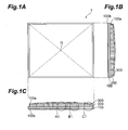
- FIGs. 1A to 1C are views showing a structure of an embodiment of a radiation image converting panel according to the present invention.
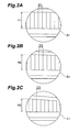
- Figs. 2A to 2C are views showing sectional structures of respective parts in a radiation converting film of a radiation image converting panel according to the present invention
- Figs. 3A to 3C are views for concretely explaining a method for specifying a central area and a peripheral area on the first main surface of a support body;
- Figs. 4A to 4E are views for explaining various embodiments of a radiation converting film in a radiation image converting panel according to the present invention.
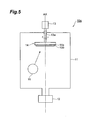
- Fig. 5 is a view showing a configuration of a manufacturing apparatus for forming, on a support body, a radiation converting film with a flat surface, as a part of the manufacturing process of a radiation image converting panel according to the present invention
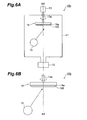
- Figs. 6A and 6B are views showing a configuration of a manufacturing apparatus for forming, on a support body, a radiation converting film with a film thickness reduced from the vicinity of the center toward the periphery, as a part of the manufacturing process of a radiation image converting panel according to the present invention
- Figs. 7A and 7B are views showing a configuration of a manufacturing apparatus for forming, on a support body, a radiation converting film with a film thickness increased from the vicinity of the center toward the periphery, as a part of the manufacturing process of a radiation image converting panel according to the present invention
- Figs. 8A and 8B are a table and a graph showing relationships between the film thickness and luminance of radiation converting films
- Figs. 9A and 9B are graphs showing relationships between the distance from the gravity center position and the luminance, with regard to radiation converting films according to comparative examples before and after formation of protective films;
- Figs. 10A and 10B are graphs showing relationships between the distance from the gravity center position and the luminance value, with regard to samples of radiation converting films (each forming a part of a radiation image converting panel according to the present invention) before and after formation of protective films.
- Figs. 1A to 1C are views showing a structure of an embodiment of a radiation image converting panel according to the present invention.
- Figs. 1A is a plan view of the radiation image converting panel 1
- Fig. 1B is a sectional view of the radiation image converting panel 1 along the line I-I in Fig. 1A
- Fig. 1C is a sectional view of the radiation image converting panel 1 along the line II-II in Fig. 1A .
- the radiation image converting panel 1 comprises a support body 100, a radiation converting film 200 formed on the support body 100, and a protective film 300 (transparent organic film) that wholly covers the support body 100 and the radiation converting film 200.
- the support body 100 is a parallel plate having a first main surface 100a on which the radiation converting film 200 is formed and a second main surface 100b opposing the first main surface 100a.
- an anti-corrosion film such as an anodic oxidation film is preferably formed on the surface thereof.
- the radiation converting film 200 is formed on a film forming region R.
- the film forming region R exists within the first main surface 100a of the support body 100 and includes at least a gravity center position G of the first main surface 100a.
- This radiation converting film 200 is comprised of columnar crystals which are coincident or tilted at a predetermined angle with respect to a normal direction of the first main surface 100a.
- Figs. 2A to 2C are views showing sectional structures of respective parts in a radiation converting film according to the present invention.
- Fig. 2A is a sectional view of a region A 1 in Fig. 1C
- Fig. 2B is a sectional view of a region B 1 in Fig. 1C
- Fig. 2C is a sectional view of a region C 1 in Fig. 1C .
- the crystal diameters D1 to D3 of columnar crystals that form the radiation converting film 200 are all approximately 7 ⁇ m, which are almost uniform across the entire surface of the radiation converting film 200.
- the radiation converting film 200 has been doped with Eu being an activator, and for the film thickness of the radiation converting film 200, in consideration of a change in luminance distribution between before and after formation of a protective film 300, the sectional shape is adjusted so as to meet a specific purpose.
- Figs. 3A to 3C description will be given, in terms of a film forming region R in the first main surface 100a of the support body 100, of a central area AR1, a peripheral area AR2, and a middle area AR3 of the film forming region R for defining a film thickness distribution of the radiation converting film 200 to be formed on the film forming region R.
- Fig. 3A is a view for concretely explaining a method for specifying a central area AR1 and a peripheral area AR2 in the first main surface 100a (film forming region R) of the support body 100.
- the central area AR1 in the film forming region R is a local region including the gravity center position G
- this is a local region including the gravity center position G whose radius equals 5% of a minimum distance W min from the gravity center position G to an edge of the film forming region R. Accordingly, a distance from the gravity center position G to a contour of the central area AR1 is given by W 0.05 .
- the peripheral area AR2 in the film forming region R is a local region sandwiched by the edge of the film forming region R and the circumference of a circle whose radius equals 40% to 80% of the minimum distance W min from the gravity center position G to an edge of the film forming region R.
- the radius is given at this time by a distance W 0.8 (when the distance is 80% of the minimum distance W min ) from the gravity center position G to the circumference.
- the middle area AR3 is a region sandwiched by the contour of the central area AR1 and the circumference of the circle to define the peripheral area AR2.
- the radiation converting film 200 is formed on the film forming region R of the first main surface 100a where the central area AR1, the peripheral area AR2, and the middle area AR3 are thus defined, and the vicinity of the center and periphery of the radiation converting film 200 may be considered as regions substantially coincident with the central area AR1 and the peripheral area AR2 defined in Fig. 3A , respectively.
- the radiation converting film 200 has a sectional shape (for example, a section along the line II-II in Fig. 1A ) of any one of a convex sectional shape, a sectional W-shape, a concave sectional shape, and a sectional M-shape, in order to arbitrarily control the luminance distribution of the panel surface after formation of the protective film 300.
- a sectional shape for example, a section along the line II-II in Fig. 1A ) of any one of a convex sectional shape, a sectional W-shape, a concave sectional shape, and a sectional M-shape, in order to arbitrarily control the luminance distribution of the panel surface after formation of the protective film 300.
- the film thickness monotonically decreases from a maximum film thickness point, which is located on the central area AR1 and corresponds to a position where the film thickness of the radiation converting film 200 is maximized (for example, the gravity center position G), toward a minimum film thickness point, which is located on the peripheral area AR2 and corresponds to a position where the film thickness of the radiation converting film 200 is minimized (for example, a position where a distance from the gravity center position G is W 0.8 ).
- a maximum film thickness point which is located on the central area AR1 and corresponds to a position where the film thickness of the radiation converting film 200 is maximized (for example, the gravity center position G)
- a minimum film thickness point which is located on the peripheral area AR2 and corresponds to a position where the film thickness of the radiation converting film 200 is minimized (for example, a position where a distance from the gravity center position G is W 0.8 ).
- 3B is a graph showing a relationship between the distance and a change in film thickness, wherein the maximum film thickness point, which is located on the central area AR1 and corresponds to the gravity center position G where the film thickness of the radiation converting film 200 is maximized, is assumed as the origin, a distance (>0) from the maximum film thickness point is assumed as the horizontal axis, and a film thickness (>0) of the radiation converting film 200 at a position corresponding to the distance from the maximum film thickness point is assumed as the longitudinal axis.
- the support body 100 assumes a minimum size of 100mm ⁇ 100mm and a maximum size of 1000mm ⁇ 1000mm.
- the radiation converting film 200 has a film thickness of 100 ⁇ m to 1100 ⁇ m.
- an allowable range of variation in film thickness of the radiation converting film 200 is ⁇ 100 ⁇ m, preferably, ⁇ 80 ⁇ m (when a variation in film thickness of the entire surface of the film forming region R is provided as ⁇ 100 ⁇ m at a maximum, ⁇ 80 ⁇ m at a position of the distance W 0.8 ).
- the film thickness at the position separated from the gravity center position G by the distance W 0.8 (the minimum distance W min is 50mm, and a distance that equals 80% thereof is 40mm) is reduced by 80 ⁇ m at a maximum from the film thickness of the radiation converting film 200 at the gravity center position G
- the film thickness monotonically increases from a minimum film thickness point, which is located on the central area AR1 and corresponds to a position where the film thickness of the radiation converting film 200 is minimized (for example, the gravity center position G), toward a maximum film thickness point, which is located on the peripheral area AR2 and corresponds to a position where the film thickness of the radiation converting film 200 is maximized (for example, a position where a distance from the gravity center position G is W 0.8 ).
- a minimum film thickness point which is located on the central area AR1 and corresponds to a position where the film thickness of the radiation converting film 200 is minimized (for example, the gravity center position G)
- a maximum film thickness point which is located on the peripheral area AR2 and corresponds to a position where the film thickness of the radiation converting film 200 is maximized (for example, a position where a distance from the gravity center position G is W 0.8 ).
- 3C is a graph showing a relationship between the distance and a change in film thickness, wherein the minimum film thickness point, which is located on the central area AR1 and corresponds to the gravity center position G where the film thickness of the radiation converting film 200 is minimized, is assumed as the origin, a distance (>0) from the minimum film thickness point is assumed as the horizontal axis, and a film thickness (>0) of the radiation converting film 200 at a position corresponding to the distance from the minimum film thickness point is assumed as the longitudinal axis.
- Figs. 4A and 4B are views for explaining various embodiments of the radiation converting film in a radiation image converting panel 1 according to the present invention.
- the sections shown in Figs. 4A to 4E are sectional views along the line II-II in Fig. 1A .
- Fig. 4A is a sectional view of a radiation image converting panel having a radiation converting film formed so that the film thickness becomes uniform, prepared for a comparison.
- the radiation image converting panel according to a comparative example shown in Fig. 4A includes a radiation converting film having a flat sectional shape without a change in film thickness between the vicinity of the center and periphery.
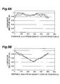
- Such a radiation image converting panel showed a sharp drop in luminance in the vicinity of the center of the panel after formation of a protective film, and a luminance unevenness occurred in the panel as a whole (see Figs. 9A and 9B to be described later).
- Fig. 4B is a sectional view of the radiation image converting panel 1 according to the present invention, which includes a radiation converting film 200 having a convex sectional shape.
- a radiation converting film 200 having such a convex sectional shape is adopted, an effect that a luminance distribution of the panel surface after formation of a protective film becomes flat is obtained.
- a part of the radiation converting film 200 having the maximum film thickness locates on the central area AR1, while a part of the radiation converting film 200 having the minimum film thickness locates on the peripheral area AR2.
- a change in film thickness at this time is represented by a monotonic decreasing function with a gradient "a" that satisfies -0.002 ⁇ a ⁇ 0, as shown in Fig. 3B .
- Fig. 4C is a sectional view of the radiation image converting panel 1 according to the present invention, which includes a radiation converting film 200 having a sectional W-shape.
- a radiation converting film 200 having such a sectional W-shape is adopted, there is an effect, on the panel surface after formation of a protective film, that the luminance in the vicinity of the center of the panel can further be increased while wholly maintaining a luminance equal to or more than an average luminance of the radiation converting film 200 having a flat sectional shape in Fig. 4A .
- the film thickness of the radiation converting film 200 located on the peripheral area AR2 monotonically increases from the middle area AR3 toward the edge of the film forming region R.
- Fig. 4D is a sectional view of the radiation image converting panel 1 according to the present invention, which includes a radiation converting film 200 having a concave sectional shape.
- a radiation converting film 200 having such a concave sectional shape is adopted, an effect that the luminance in the periphery of the panel is increased is obtained on the panel surface after formation of a protective film.
- the radiation converting film 200 having such a concave sectional shape is effective when an attention imaging region exists in the periphery of the panel.
- a part of the radiation converting film 200 having the minimum film thickness exists on the central area AR1, while a part of the radiation converting film 200 having the maximum film thickness locates on the peripheral area AR2.
- a change in film thickness at this time is represented by a monotonic increasing function with a gradient "b" that satisfies 0 ⁇ b ⁇ 0.002, as shown in Fig. 3C .
- Fig. 4E is a sectional view of the radiation image converting panel 1 according to the present invention, which includes a radiation converting film 200 having a sectional M-shape.
- a radiation converting film 200 having such a sectional M-shape is adopted, an effect to make the effect of the sectional concave shape shown in Fig. 4D further prominent is obtained on the panel surface after formation of a protective film.
- the film thickness of the radiation converting film 200 on the peripheral area AR2 monotonically decreases from the middle area AR3 toward the edge of the film forming region R.
- the radiation image converting panel 1 specifically, the radiation converting film 200 provided on the support body 100 is formed by a manufacturing apparatus shown in any one of Figs. 5 and 6A to 7B . More specifically, by controlling the position to install a phosphor evaporation source and the inflow direction of a metal vapor in each of the manufacturing apparatuses shown in Fig. 5 and 6A to 7B , the radiation converting films 200 having various sectional structures as shown in Figs. 4B to 4E are obtained.
- Fig. 5 is a view showing a configuration of a manufacturing apparatus 10a for forming, on the support body 100, a radiation converting film 200 with a flat surface (a flat sectional shape), as a part of the manufacturing process of the radiation image converting panel 1 according to the present invention.
- the manufacturing apparatus 10a shown in Fig. 5 is an apparatus that forms a radiation converting film 200 on the first main surface 100a of the support body 100 by a vapor-phase deposition method.
- a vapor-phase deposition method a vapor deposition method, a sputtering method, a CVD method, an ion plating method, or the like is applicable, and description will be given for, as an example, a case where the radiation converting film 200 of Eu-doped CsBr is formed on the support body 100 by a vapor deposition method.
- This manufacturing apparatus 10a includes, at least, a vacuum container 11, a support body holder 14, a rotary shaft 13a, a drive unit 13, a phosphor evaporation source 15, and a vacuum pump 12.
- the support body holder 14, the evaporation source 15, and a part of the rotary shaft 13 a are arranged in the vacuum container 11.
- the support body holder 14 includes a heater 14a to heat the support body 100.
- One end of the rotary shaft 13a extended from the drive unit 13 is attached to the support body holder 14, and the drive unit 13 rotates the support body holder 14 via the rotary shaft 13a.
- the vacuum pump 12 depressurizes the interior of the vacuum container 11 to a predetermined degree of vacuum.
- the phosphor evaporation source 15 a mixture material of CsBr and EuBr is set. Moreover, the phosphor evaporation source 15 is set so that the inflow direction of a metal vapor points to the middle area AR3 of the support body 100 from the position off the axis AX.
- the support body 100 is set on the support body holder 14.
- the crystal diameter of columnar crystals to be formed on a surface, of the support body 100, facing the phosphor evaporation source 15 is adjusted by adjusting the temperature of the support body 100 itself with the heater 14a, and by controlling the degree of vacuum in the vacuum container 11, an inflow angle of the metal vapor from the material source 15 to the support body 100, and the like.
- columnar crystals of Eu-doped CsBr are grown on the first main surface 100a (the surface facing the phosphor evaporation source 15) of the support body 100 by a vapor deposition method.
- the drive unit 13 is rotating the support body holder 14 via the rotary shaft 13a, and accordingly, the support body 100 is also rotating around the axis AX.
- a radiation converting film 200 with a film thickness of 500 ⁇ m ⁇ 50 ⁇ m is formed on the support body 100.
- the crystal diameter of columnar crystals of the radiation converting film 200 is approximately 3 ⁇ m to 10 ⁇ m on average.
- Figs. 6A and 6B are views showing a configuration of a manufacturing apparatus 10b for forming, on the support body 100, a radiation converting film 200 with a film thickness reduced from the vicinity of the center toward the periphery (a convex sectional shape), as a part of the manufacturing process of the radiation image converting panel 1 according to the present invention.
- the manufacturing apparatus 10b shown in Figs. 6A and 6B differs from the manufacturing apparatus 10a shown in Fig. 5 in terms of arrangement of the phosphor evaporation source 15 and inflow direction of a metal vapor.
- the phosphor evaporation source 15 is installed at a position off the axis AX, and the inflow direction of a metal vapor from the phosphor evaporation source 15 is oriented to the middle area AR3 located at an opposite side across the axis AX in a manner crossing the axis AX.
- a radiation converting film 200 having a convex sectional shape as shown in Fig. 4B is formed on the first main surface 100a of the support body 100.
- Fig. 6B discloses only a main part of Fig. 6A , which differs from the case of Fig.
- Figs. 7A and 7B are views showing a configuration of a manufacturing apparatus 10c for forming, on the support body 100, a radiation converting film 200 with a film thickness increased from the vicinity of the center toward the periphery (a concave sectional shape), as a part of the manufacturing process of the radiation image converting panel 1 according to the present invention.
- the manufacturing apparatus 10c shown in Figs. 7A and 7B differs from the manufacturing apparatuses 10a and 10b shown in Figs. 5 , 6A, and 6B in terms of arrangement of the phosphor evaporation source 15 and inflow direction of a metal vapor.
- the phosphor evaporation source 15 is installed in the vicinity of the support body 100, and the inflow direction of a metal vapor from the phosphor evaporation source 15 is oriented to the peripheral area AR2 of the support body 100 (namely, the edge of the support body 100).
- a radiation converting film 200 having a concave sectional shape as shown in Fig. 4D is formed on the first main surface 100a of the support body 100.
- Fig. 7B discloses only a main part of Fig. 7A , which differs from the case of Fig. 7A in position to install the phosphor evaporation source 15.
- the phosphor evaporation source 15 is installed in a manner separated from the support body 100 further than in the case of Fig. 7A , while the inflow direction of a metal vapor therefrom is oriented to the edge of the support body 100 as in the case of Fig. 7A .
- a radiation converting film 200 having a concave sectional shape as shown in Fig. 4D is obtained.
- the radiation converting films 200 having such special sectional shapes as in Figs. 4C and 4E are formed, it suffices to combine the evaporation source arrangements shown in Fig. 5 and 6A to 7B described above.
- the radiation converting film 200 having a sectional W-shape shown in Fig. 4C is obtained by combining the arrangement for a sectional convex shape shown in Fig. 6A or 6B and the arrangement for a sectional concave shape shown in Fig. 7A or 7B .
- the radiation converting film 200 having a sectional M-shape shown in Fig. 4E is obtained by combining the arrangement for a flat sectional shape shown in Fig. 5 and the arrangement for a sectional convex shape (where the inflow direction of a metal vapor being off the center of the support body 100) shown in Fig. 6A or 6B .
- the CsBr being a material of the radiation converting film 200 formed on the support body 100 by any one of the manufacturing apparatuses 10a to 10c of Figs. 5 and 6A to 7B or combining these as described above is highly hygroscopic.
- the radiation converting film 200 absorbs vapor in the air to deliquesce when this is kept exposed. Therefore, subsequent to the forming step of the radiation converting film 200 by a vapor deposition method, a moisture-resistant protective film 300 is formed by a CVD method so as to cover an entire exposed surface of the radiation converting film 200.
- the support body 100 on which the radiation converting film 200 has been formed is placed in a CVD apparatus, and a moisture-resistant protective film 300 with a film thickness of approximately 10 ⁇ m is formed on the exposed surface of the radiation converting film 200.
- a moisture-resistant protective film 300 with a film thickness of approximately 10 ⁇ m is formed on the exposed surface of the radiation converting film 200.
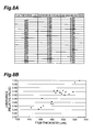
- Figs. 8A and 8B are a table and a graph showing relationships between the film thickness and luminance of the radiation converting films 200.
- Fig. 8A is a table showing numerical values when radiation converting film samples having various film thicknesses ( ⁇ m) were prepared and respective luminances were measured. In Fig. 8A , the luminances are shown as relative values (standardized values with the maximum value provided as 1).
- Fig. 8B is a graph plotting the relationships between the film thickness and luminance relative value shown in Fig. 8A .
- the radiation converting films generally have a tendency that as the film thickness increases, the luminance also increases. It can be understood from this that individually adjusting the film thicknesses of arbitrary regions of the radiation converting film 200, the luminance distribution of the panel surface can be adjusted according to usage conditions. In the following, referring to Figs. 9A to 10B , effects of luminance distribution control by the present invention will be concretely described.
- Figs. 9A and 9B are graphs showing relationships between the distance from the gravity center position and the luminance, with regard to radiation converting films according to comparative examples before and after formation of protective films.
- Two samples of radiation converting films prepared as the comparative examples have flat sectional shapes.
- Fig. 9A is a graph showing a relationship between the measuring position (displayed as the distance from the gravity center position) and the relative luminance value, with regard to two prepared samples according to the comparative examples before formation of protective films.
- Fig. 9B is a graph showing a relationship between the measuring position and the relative luminance value, with regard to two prepared samples according to the comparative examples after formation of protective films.
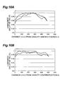
- Figs. 10A and 10B are graphs showing relationships between the distance from the gravity center position and the luminance value, with regard to radiation converting films (each forming a part of a radiation image converting panel according to the present invention) before and after formation of protective films.
- Two samples of the radiation converting films 200 to be applied to the radiation image converting panels 1 according to the present invention have convex sectional shapes.
- Fig. 10A is a graph showing a relationship between the measuring position (displayed as the distance from the gravity center position) and relative luminance value, with regard to two prepared samples before formation of protective films.
- Fig. 10B is a graph showing a relationship between the measuring position and the relative luminance value, with regard to two samples after formation of protective films.
- the present invention it becomes possible, in consideration of a change in luminance distribution of the panel surface between before and after formation of a protective film to be provided on the surface of a radiation converting film, to arbitrarily control the luminance distribution of the panel surface after formation of a protective film according to usage conditions, such as making the luminance of the panel surface as a whole uniform, or increasing luminance in only a specific attention region.
Landscapes
- Physics & Mathematics (AREA)
- Health & Medical Sciences (AREA)
- Life Sciences & Earth Sciences (AREA)
- General Physics & Mathematics (AREA)
- High Energy & Nuclear Physics (AREA)
- Molecular Biology (AREA)
- Spectroscopy & Molecular Physics (AREA)
- Chemical & Material Sciences (AREA)
- Crystallography & Structural Chemistry (AREA)
- Conversion Of X-Rays Into Visible Images (AREA)
- Apparatus For Radiation Diagnosis (AREA)
Abstract
Description
- The present invention relates to a radiation image converting panel comprising a radiation converting film having a columnar crystal structure, which converts an incident radiation ray to a visible light.
- Radiation images typified by X-ray images have conventionally been widely used for a purposes such as disease diagnosis. As a technique for obtaining such a radiation image, for example, a radiation image recording and reproducing technique using a radiation converting film that accumulates and records irradiated radiation energy, and also emits a visible light according to radiation energy accumulated and recorded as a result of irradiating an excitation light has been widely put into practical use.
- A radiation image converting panel to be applied to such a radiation image recording and reproducing technique as this includes a support body and a radiation converting film provided on the support body. As the radiation converting film, a photostimulable phosphor layer having a columnar crystal structure formed by vapor-phase growth (deposition) has been known. When the photostimulable phosphor layer has a columnar crystal structure, since a photostimulable excitation light or photostimulable emission is effectively suppressed from diffusing in the horizontal direction (reaches the support body surface while repeating reflection at crack (columnar crystal) interfaces), this allows remarkably increasing the sharpness of an image by photostimulable emission.
- For example, Japanese Patent Application Laid-Open No. H02-58000 has proposed a radiation image converting panel having a photostimulable phosphor layer for which formed by a vapor-phase deposition method on a support body are slender columnar crystals with a constant tilt with respect to a normal direction of the support body. Furthermore, Japanese Patent Application Laid-Open No.
2005-315786 - The present inventors have examined the conventional radiation image converting panels in detail, and as a result, have discovered the following problems. That is, in the conventional radiation image converting panels, luminance distribution in the panel surface has changed between before and after formation of a protective film on the surface of the radiation converting film. As an example of the change in luminance distribution, specifically, the luminance in the vicinity of the center of the panel slightly decreases, while the luminance in the periphery of the panel increases. Therefore, conventional radiation image converting panels have had luminance distribution characteristics that the luminance in the periphery of the panel is higher than that in the vicinity of the center. In an actual service condition, the vicinity of the center of the panel is considered to be most frequently used, and there has been a problem that a luminance unevenness on the panel surface becomes significant as time passes.
- The present invention has been developed to eliminate the problems described above. It is an object of the present invention to provide a radiation image converting panel with a structure capable of, in consideration of a change in luminance distribution of the panel surface between before and after formation of a protective film to be provided on the surface of a radiation converting film, arbitrarily controlling the luminance distribution of the panel surface after formation of a protective film according to usage conditions.
- A radiation image converting panel according to the present invention has been completed by the inventors' discovery that control of the film thickness of a radiation converting film makes it possible to adjust the luminance of the panel surface after formation of a protective film. In oncrete terms, a radiation image converting panel according to the present invention comprises a support body, and a radiation converting film formed on the support body. The support body includes a parallel plate having a first main surface on which the radiation converting film is formed and a second main surface opposing the first main surface. The radiation converting film is provided on a film forming region. The film forming region exists within the first main surface of the support body and includes at least a gravity center position of the first main surface. The radiation converting film is an Eu-doped photostimulable phosphor layer, and is comprised of columnar crystals which are coincident or tilted at a predetermined angle with respect to a normal direction of the first main surface.
- Particularly, in the radiation image converting panel according to the present invention, the radiation converting film has a sectional shape of any one of a convex sectional shape, a sectional W-shape, a concave sectional shape, and a sectional M-shape, in order to arbitrarily control the luminance distribution of the panel surface after formation of a protective film.
- In the case that the radiation converting film has a convex sectional shape, in the film forming region of the first main surface, a part of the radiation converting film having a maximum film thickness locates on a central area around the gravity center position whose radius equals 5% or less of a minimum distance from the gravity center position to an edge of the film forming region, while a part of the radiation converting film having a minimum film thickness locates on a peripheral area sandwiched by a circumference of a circle whose radius equals 80% of the minimum distance and the edge of the film forming region. Also, when a radiation converting film having such a convex sectional shape is adopted, an effect that a luminance distribution of the panel surface after formation of a protective film becomes flat is obtained.
- In the case that the radiation converting film has such a sectional convex shape, the film thickness of the radiation converting film monotonically decreases from a maximum film thickness point, which is located on the central area and corresponds to a position where the film thickness of the radiation converting film is maximized, toward a minimum film thickness point, which is located on the peripheral area and corresponds to a position where the film thickness of the radiation converting film is minimized. Moreover, when assuming the maximum film thickness point in the central area, corresponding to a position where the film thickness of the radiation converting film is maximized, as an origin, a distance (>0) from the maximum film thickness point as a horizontal axis, and a film thickness (>0) of the radiation converting film at a position corresponding to the distance from the maximum film thickness point as a longitudinal axis, a linear line connecting the point that indicates the maximum film thickness and the point that provides the minimum film thickness has a gradient of more than -0.002 and less than 0.
- In the case that the radiation converting film has a sectional W-shape, in the film forming region of the first main surface, a part of the radiation converting film having a maximum film thickness locates on a central area around the gravity center position whose radius equals 5% or less of a minimum distance from the gravity center position to an edge of the film forming region, while a part of the radiation converting film having a minimum film thickness locates on a middle area sandwiched by a circumference of a circle whose radius equals 80% of the minimum distance and a contour of the central area. Also, in such a sectional W-shape, the film thickness of the radiation converting film located on a peripheral area, sandwiched by the circumference of the circle defining the middle area and the edge of the film forming region, monotonically increases from the circumference of the circle defining the middle area toward the edge of the film forming region. When a radiation converting film having such a sectional W-shape is adopted, there is an effect, on the panel surface after formation of a protective film, that the luminance in the vicinity of the center of the panel can further be increased while entirely maintaining a luminance equal to or more than an average luminance of the conventional radiation converting film having a flat sectional shape.
- Furthermore, in the case that the radiation converting film has a concave sectional shape, in the film forming region of the first main surface, a part of the radiation converting film having a minimum film thickness locates on a central area around the gravity center position whose radius equals 5% or less of a minimum distance from the gravity center position to an edge of the film forming region, while a part of the radiation converting film having a maximum film thickness locates on a peripheral area sandwiched by a circumference of a circle whose radius equals 80% of the minimum distance and the edge of the film forming region. Also, the radiation converting film having such a concave sectional shape is effective when an attention imaging region exists in the periphery of the panel.
- When the radiation converting film has such a concave sectional shape, the film thickness of the radiation converting film monotonically increases from a minimum film thickness point, which is located on the central area and corresponds to a position where the film thickness of the radiation converting film is minimized, toward a maximum film thickness point, which is located on the peripheral area and corresponds to a position where the film thickness of the radiation converting film is maximized. Moreover, when assuming the minimum film thickness point in the central area, corresponding to a position where the film thickness of the radiation converting film is minimized, as an origin, a distance (>0) from the minimum film thickness point as a horizontal axis, and a film thickness (>0) of the radiation converting film at a position corresponding to the distance from the minimum film thickness point as a longitudinal axis, a linear line connecting the point that indicates the minimum film thickness and the point that provides the maximum film thickness has a gradient of more than 0 and less than 0.002.
- In the case that the radiation converting film has a sectional M-shape, in the film forming region of the first main surface, a part of the radiation converting film having a minimum film thickness locates on a central area around the gravity center position whose radius equals 5% or less of a minimum distance from the gravity center position to an edge of the film forming region, while a part of the radiation converting film having a maximum film thickness locates on a middle area sandwiched by a circumference of a circle whose radius equals 80% of the minimum distance and a contour of the central area. Also, in such a sectional M-shape, the film thickness of the radiation converting film located on a peripheral area, which is sandwiched by the circumference of the circle defining the middle area and the edge of the film forming region, monotonically decreases from the circumference of the circle defining the middle area toward the edge of the film forming region. When a radiation converting film having such a sectional M-shape is adopted, an effect to make the effect of the sectional concave shape described above further prominent is obtained on the panel surface after formation of a protective film.
- Furthermore, the radiation image converting panel according to the present invention may include a moisture-resistant protective film (transparent organic film) that covers an exposed surface of the radiation converting film excluding a surface covered by the first main surface of the support body.
- The present invention will be more fully understood from the detailed description given hereinbelow and the accompanying drawings, which are given by way of illustration only and are not to be considered as limiting the present invention.
- Further scope of applicability of the present invention will become apparent from the detailed description given hereinafter. However, it should be understood that the detailed description and specific examples, while indicating preferred embodiments of the invention, are given by way of illustration only, since various changes and modifications within the scope of the invention will be apparent to those skilled in the art from this detailed description.
-
Figs. 1A to 1C are views showing a structure of an embodiment of a radiation image converting panel according to the present invention; -
Figs. 2A to 2C are views showing sectional structures of respective parts in a radiation converting film of a radiation image converting panel according to the present invention; -
Figs. 3A to 3C are views for concretely explaining a method for specifying a central area and a peripheral area on the first main surface of a support body; -
Figs. 4A to 4E are views for explaining various embodiments of a radiation converting film in a radiation image converting panel according to the present invention; -
Fig. 5 is a view showing a configuration of a manufacturing apparatus for forming, on a support body, a radiation converting film with a flat surface, as a part of the manufacturing process of a radiation image converting panel according to the present invention; -
Figs. 6A and 6B are views showing a configuration of a manufacturing apparatus for forming, on a support body, a radiation converting film with a film thickness reduced from the vicinity of the center toward the periphery, as a part of the manufacturing process of a radiation image converting panel according to the present invention; -
Figs. 7A and 7B are views showing a configuration of a manufacturing apparatus for forming, on a support body, a radiation converting film with a film thickness increased from the vicinity of the center toward the periphery, as a part of the manufacturing process of a radiation image converting panel according to the present invention; -
Figs. 8A and 8B are a table and a graph showing relationships between the film thickness and luminance of radiation converting films; -
Figs. 9A and 9B are graphs showing relationships between the distance from the gravity center position and the luminance, with regard to radiation converting films according to comparative examples before and after formation of protective films; and -
Figs. 10A and 10B are graphs showing relationships between the distance from the gravity center position and the luminance value, with regard to samples of radiation converting films (each forming a part of a radiation image converting panel according to the present invention) before and after formation of protective films. - In the following, embodiments of a radiation image converting panel according to the present invention will be explained in detail with reference to
Figs. 1A to 4E, 5 , and6A to 10B . In the description of the drawings, identical or corresponding components are designated by the same reference numerals, and overlapping description is omitted. -
Figs. 1A to 1C are views showing a structure of an embodiment of a radiation image converting panel according to the present invention. In particular,Figs. 1A is a plan view of the radiationimage converting panel 1,Fig. 1B is a sectional view of the radiationimage converting panel 1 along the line I-I inFig. 1A, and Fig. 1C is a sectional view of the radiationimage converting panel 1 along the line II-II inFig. 1A . - In
Figs. 1A to 1C , the radiationimage converting panel 1 comprises asupport body 100, aradiation converting film 200 formed on thesupport body 100, and a protective film 300 (transparent organic film) that wholly covers thesupport body 100 and theradiation converting film 200. Thesupport body 100 is a parallel plate having a firstmain surface 100a on which theradiation converting film 200 is formed and a secondmain surface 100b opposing the firstmain surface 100a. Moreover, when thesupport body 100 is made of a corrodible metal material such as Al, an anti-corrosion film such as an anodic oxidation film is preferably formed on the surface thereof. Theradiation converting film 200 is formed on a film forming region R. The film forming region R exists within the firstmain surface 100a of thesupport body 100 and includes at least a gravity center position G of the firstmain surface 100a. Thisradiation converting film 200 is comprised of columnar crystals which are coincident or tilted at a predetermined angle with respect to a normal direction of the firstmain surface 100a. -
Figs. 2A to 2C are views showing sectional structures of respective parts in a radiation converting film according to the present invention. In concrete terms,Fig. 2A is a sectional view of aregion A 1 inFig. 1C ,Fig. 2B is a sectional view of aregion B 1 inFig. 1C , andFig. 2C is a sectional view of aregion C 1 inFig. 1C . - As can be understood from
Figs. 2A to 2C , the crystal diameters D1 to D3 of columnar crystals that form theradiation converting film 200 are all approximately 7µm, which are almost uniform across the entire surface of theradiation converting film 200. However, theradiation converting film 200 has been doped with Eu being an activator, and for the film thickness of theradiation converting film 200, in consideration of a change in luminance distribution between before and after formation of aprotective film 300, the sectional shape is adjusted so as to meet a specific purpose. - Next, by use of
Figs. 3A to 3C , description will be given, in terms of a film forming region R in the firstmain surface 100a of thesupport body 100, of a central area AR1, a peripheral area AR2, and a middle area AR3 of the film forming region R for defining a film thickness distribution of theradiation converting film 200 to be formed on the film forming region R.Fig. 3A is a view for concretely explaining a method for specifying a central area AR1 and a peripheral area AR2 in the firstmain surface 100a (film forming region R) of thesupport body 100. - As shown in
Fig. 3A , the central area AR1 in the film forming region R is a local region including the gravity center position G In concrete terms, this is a local region including the gravity center position G whose radius equals 5% of a minimum distance Wmin from the gravity center position G to an edge of the film forming region R. Accordingly, a distance from the gravity center position G to a contour of the central area AR1 is given by W0.05. On the other hand, the peripheral area AR2 in the film forming region R is a local region sandwiched by the edge of the film forming region R and the circumference of a circle whose radius equals 40% to 80% of the minimum distance Wmin from the gravity center position G to an edge of the film forming region R. The radius is given at this time by a distance W0.8 (when the distance is 80% of the minimum distance Wmin) from the gravity center position G to the circumference. Moreover, the middle area AR3 is a region sandwiched by the contour of the central area AR1 and the circumference of the circle to define the peripheral area AR2. - Also, the
radiation converting film 200 is formed on the film forming region R of the firstmain surface 100a where the central area AR1, the peripheral area AR2, and the middle area AR3 are thus defined, and the vicinity of the center and periphery of theradiation converting film 200 may be considered as regions substantially coincident with the central area AR1 and the peripheral area AR2 defined inFig. 3A , respectively. - The
radiation converting film 200 has a sectional shape (for example, a section along the line II-II inFig. 1A ) of any one of a convex sectional shape, a sectional W-shape, a concave sectional shape, and a sectional M-shape, in order to arbitrarily control the luminance distribution of the panel surface after formation of theprotective film 300. - Particularly, in the case that the
radiation converting film 200 has a convex sectional shape, as shown in, for example,Fig. 3B , the film thickness monotonically decreases from a maximum film thickness point, which is located on the central area AR1 and corresponds to a position where the film thickness of theradiation converting film 200 is maximized (for example, the gravity center position G), toward a minimum film thickness point, which is located on the peripheral area AR2 and corresponds to a position where the film thickness of theradiation converting film 200 is minimized (for example, a position where a distance from the gravity center position G is W0.8). Also,Fig. 3B is a graph showing a relationship between the distance and a change in film thickness, wherein the maximum film thickness point, which is located on the central area AR1 and corresponds to the gravity center position G where the film thickness of theradiation converting film 200 is maximized, is assumed as the origin, a distance (>0) from the maximum film thickness point is assumed as the horizontal axis, and a film thickness (>0) of theradiation converting film 200 at a position corresponding to the distance from the maximum film thickness point is assumed as the longitudinal axis. - The
support body 100 assumes a minimum size of 100mm×100mm and a maximum size of 1000mm×1000mm. At this time, theradiation converting film 200 has a film thickness of 100µm to 1100µm. When reading a radiation image accumulated in a photostimulable phosphor layer serving as theradiation converting film 200 by a scanner, for avoiding a deterioration in the S/N ratio whenever possible, an allowable range of variation in film thickness of theradiation converting film 200 is ±100µm, preferably, ±80µm (when a variation in film thickness of the entire surface of the film forming region R is provided as ±100µm at a maximum, ±80µm at a position of the distance W0.8). - In concrete terms, when the
support body 100 has a size of 100mm×100mm (the film forming region R has a slightly smaller size), the film thickness at the position separated from the gravity center position G by the distance W0.8 (the minimum distance Wmin is 50mm, and a distance that equals 80% thereof is 40mm) is reduced by 80µm at a maximum from the film thickness of theradiation converting film 200 at the gravity center position G At this time, a gradient "a" of the graph shown inFig. 3B is -0.0002 (= -0.008mm/40mm). Accordingly, when theradiation converting film 200 has a convex sectional shape, the gradient "a" of the graph showing a change in film thickness (monotonic decrease) satisfies -0.002<a<0. - On the other hand, in the case that the
radiation converting film 200 has a concave sectional shape, as shown in, for example,Fig. 3C , the film thickness monotonically increases from a minimum film thickness point, which is located on the central area AR1 and corresponds to a position where the film thickness of theradiation converting film 200 is minimized (for example, the gravity center position G), toward a maximum film thickness point, which is located on the peripheral area AR2 and corresponds to a position where the film thickness of theradiation converting film 200 is maximized (for example, a position where a distance from the gravity center position G is W0.8). Also,Fig. 3C is a graph showing a relationship between the distance and a change in film thickness, wherein the minimum film thickness point, which is located on the central area AR1 and corresponds to the gravity center position G where the film thickness of theradiation converting film 200 is minimized, is assumed as the origin, a distance (>0) from the minimum film thickness point is assumed as the horizontal axis, and a film thickness (>0) of theradiation converting film 200 at a position corresponding to the distance from the minimum film thickness point is assumed as the longitudinal axis. - For calculating a gradient "b" of the graph shown in
Fig. 3C under the same conditions as those in the case ofFig. 3B , when thesupport body 100 has a size of 100mm×100mm (the film forming region R has a slightly smaller size), the film thickness at the position separated from the gravity center position G by the distance W0.8 (the minimum distance Wmin is 50mm, and a distance that equals 80% thereof is 40mm) is increased by 80µm at a maximum from the film thickness of theradiation converting film 200 at the gravity center position G At this time, a gradient "b" of the graph shown in Fis. 3C is 0.0002 (= 0.008mm/40mm). Accordingly, when theradiation converting film 200 has a concave sectional shape, the gradient "b" of the graph showing a change in film thickness (monotonic increase) satisfies 0<b<0.002. - Next, description will be given of a concrete sectional structure of the
radiation converting film 200 to be applied to the radiationimage converting panel 1 according to the present invention.Figs. 4A and 4B are views for explaining various embodiments of the radiation converting film in a radiationimage converting panel 1 according to the present invention. The sections shown inFigs. 4A to 4E are sectional views along the line II-II inFig. 1A . Also,Fig. 4A is a sectional view of a radiation image converting panel having a radiation converting film formed so that the film thickness becomes uniform, prepared for a comparison. - The radiation image converting panel according to a comparative example shown in
Fig. 4A includes a radiation converting film having a flat sectional shape without a change in film thickness between the vicinity of the center and periphery. Such a radiation image converting panel showed a sharp drop in luminance in the vicinity of the center of the panel after formation of a protective film, and a luminance unevenness occurred in the panel as a whole (seeFigs. 9A and 9B to be described later). -
Fig. 4B is a sectional view of the radiationimage converting panel 1 according to the present invention, which includes aradiation converting film 200 having a convex sectional shape. In the case that aradiation converting film 200 having such a convex sectional shape is adopted, an effect that a luminance distribution of the panel surface after formation of a protective film becomes flat is obtained. - In the
radiation converting film 200 having a convex sectional shape, a part of theradiation converting film 200 having the maximum film thickness locates on the central area AR1, while a part of theradiation converting film 200 having the minimum film thickness locates on the peripheral area AR2. A change in film thickness at this time is represented by a monotonic decreasing function with a gradient "a" that satisfies -0.002<a<0, as shown inFig. 3B . -
Fig. 4C is a sectional view of the radiationimage converting panel 1 according to the present invention, which includes aradiation converting film 200 having a sectional W-shape. In the case that aradiation converting film 200 having such a sectional W-shape is adopted, there is an effect, on the panel surface after formation of a protective film, that the luminance in the vicinity of the center of the panel can further be increased while wholly maintaining a luminance equal to or more than an average luminance of theradiation converting film 200 having a flat sectional shape inFig. 4A . - In the
radiation converting film 200 having a sectional W-shape, a part of theradiation converting film 200 having the maximum film thickness exists on the central area AR1, while a part of theradiation converting film 200 having the minimum film thickness locates on the middle area AR3. Moreover, the film thickness of theradiation converting film 200 located on the peripheral area AR2 monotonically increases from the middle area AR3 toward the edge of the film forming region R. -
Fig. 4D is a sectional view of the radiationimage converting panel 1 according to the present invention, which includes aradiation converting film 200 having a concave sectional shape. In the case that aradiation converting film 200 having such a concave sectional shape is adopted, an effect that the luminance in the periphery of the panel is increased is obtained on the panel surface after formation of a protective film. Theradiation converting film 200 having such a concave sectional shape is effective when an attention imaging region exists in the periphery of the panel. - In the
radiation converting film 200 having a sectional concave shape, a part of theradiation converting film 200 having the minimum film thickness exists on the central area AR1, while a part of theradiation converting film 200 having the maximum film thickness locates on the peripheral area AR2. A change in film thickness at this time is represented by a monotonic increasing function with a gradient "b" that satisfies 0<b<0.002, as shown inFig. 3C . -
Fig. 4E is a sectional view of the radiationimage converting panel 1 according to the present invention, which includes aradiation converting film 200 having a sectional M-shape. In the case that aradiation converting film 200 having such a sectional M-shape is adopted, an effect to make the effect of the sectional concave shape shown inFig. 4D further prominent is obtained on the panel surface after formation of a protective film. - In the
radiation converting film 200 having a sectional M-shape, a part of theradiation converting film 200 having the minimum film thickness exists on the central area AR1, while a part of theradiation converting film 200 having the maximum film thickness locates on the middle area AR3. Moreover, the film thickness of theradiation converting film 200 on the peripheral area AR2 monotonically decreases from the middle area AR3 toward the edge of the film forming region R. - The radiation
image converting panel 1 according to the present invention, specifically, theradiation converting film 200 provided on thesupport body 100 is formed by a manufacturing apparatus shown in any one ofFigs. 5 and6A to 7B . More specifically, by controlling the position to install a phosphor evaporation source and the inflow direction of a metal vapor in each of the manufacturing apparatuses shown inFig. 5 and6A to 7B , theradiation converting films 200 having various sectional structures as shown inFigs. 4B to 4E are obtained. - First,
Fig. 5 is a view showing a configuration of amanufacturing apparatus 10a for forming, on thesupport body 100, aradiation converting film 200 with a flat surface (a flat sectional shape), as a part of the manufacturing process of the radiationimage converting panel 1 according to the present invention. - The
manufacturing apparatus 10a shown inFig. 5 is an apparatus that forms aradiation converting film 200 on the firstmain surface 100a of thesupport body 100 by a vapor-phase deposition method. As the vapor-phase deposition method, a vapor deposition method, a sputtering method, a CVD method, an ion plating method, or the like is applicable, and description will be given for, as an example, a case where theradiation converting film 200 of Eu-doped CsBr is formed on thesupport body 100 by a vapor deposition method. Thismanufacturing apparatus 10a includes, at least, avacuum container 11, asupport body holder 14, arotary shaft 13a, adrive unit 13, aphosphor evaporation source 15, and avacuum pump 12. Thesupport body holder 14, theevaporation source 15, and a part of therotary shaft 13 a are arranged in thevacuum container 11. Thesupport body holder 14 includes aheater 14a to heat thesupport body 100. One end of therotary shaft 13a extended from thedrive unit 13 is attached to thesupport body holder 14, and thedrive unit 13 rotates thesupport body holder 14 via therotary shaft 13a. Thephosphor evaporation source 15, which is arranged at a position deviated from a center axis AX of thevacuum container 11, holds a metal material supplied as a metal vapor to be vapor-deposited on thesupport body 100 installed on thesupport body holder 14. Thevacuum pump 12 depressurizes the interior of thevacuum container 11 to a predetermined degree of vacuum. - In the
phosphor evaporation source 15, a mixture material of CsBr and EuBr is set. Moreover, thephosphor evaporation source 15 is set so that the inflow direction of a metal vapor points to the middle area AR3 of thesupport body 100 from the position off the axis AX. Thesupport body 100 is set on thesupport body holder 14. The crystal diameter of columnar crystals to be formed on a surface, of thesupport body 100, facing thephosphor evaporation source 15 is adjusted by adjusting the temperature of thesupport body 100 itself with theheater 14a, and by controlling the degree of vacuum in thevacuum container 11, an inflow angle of the metal vapor from thematerial source 15 to thesupport body 100, and the like. - First, columnar crystals of Eu-doped CsBr are grown on the first
main surface 100a (the surface facing the phosphor evaporation source 15) of thesupport body 100 by a vapor deposition method. At this time, thedrive unit 13 is rotating thesupport body holder 14 via therotary shaft 13a, and accordingly, thesupport body 100 is also rotating around the axis AX. - By such a vapor deposition method, a
radiation converting film 200 with a film thickness of 500µm±50µm is formed on thesupport body 100. At this time, the crystal diameter of columnar crystals of theradiation converting film 200 is approximately 3µm to 10µm on average. -
Figs. 6A and 6B are views showing a configuration of amanufacturing apparatus 10b for forming, on thesupport body 100, aradiation converting film 200 with a film thickness reduced from the vicinity of the center toward the periphery (a convex sectional shape), as a part of the manufacturing process of the radiationimage converting panel 1 according to the present invention. Themanufacturing apparatus 10b shown inFigs. 6A and 6B differs from themanufacturing apparatus 10a shown inFig. 5 in terms of arrangement of thephosphor evaporation source 15 and inflow direction of a metal vapor. - More specifically, in the
manufacturing apparatus 10b shown inFig. 6A , thephosphor evaporation source 15 is installed at a position off the axis AX, and the inflow direction of a metal vapor from thephosphor evaporation source 15 is oriented to the middle area AR3 located at an opposite side across the axis AX in a manner crossing the axis AX. As a result of thephosphor evaporation source 15 being thus installed, aradiation converting film 200 having a convex sectional shape as shown inFig. 4B is formed on the firstmain surface 100a of thesupport body 100. Meanwhile,Fig. 6B discloses only a main part ofFig. 6A , which differs from the case ofFig. 6A in position to install thephosphor evaporation source 15. That is, in theapparatus 10b shown inFig. 6B , the inflow direction of a metal vapor from thephosphor evaporation source 15 is oriented to the central area AR1 of thesupport body 100. Thus, as a result of thephosphor evaporation source 15 being installed as shown inFig. 6B as well, aradiation converting film 200 having a convex sectional shape as shown inFig. 4B is obtained. - Furthermore,
Figs. 7A and 7B are views showing a configuration of amanufacturing apparatus 10c for forming, on thesupport body 100, aradiation converting film 200 with a film thickness increased from the vicinity of the center toward the periphery (a concave sectional shape), as a part of the manufacturing process of the radiationimage converting panel 1 according to the present invention. Themanufacturing apparatus 10c shown inFigs. 7A and 7B differs from themanufacturing apparatuses Figs. 5 ,6A, and 6B in terms of arrangement of thephosphor evaporation source 15 and inflow direction of a metal vapor. - More specifically, in the
manufacturing apparatus 10c shown inFig. 7A , thephosphor evaporation source 15 is installed in the vicinity of thesupport body 100, and the inflow direction of a metal vapor from thephosphor evaporation source 15 is oriented to the peripheral area AR2 of the support body 100 (namely, the edge of the support body 100). As a result of thephosphor evaporation source 15 being thus installed, aradiation converting film 200 having a concave sectional shape as shown inFig. 4D is formed on the firstmain surface 100a of thesupport body 100. Meanwhile,Fig. 7B discloses only a main part ofFig. 7A , which differs from the case ofFig. 7A in position to install thephosphor evaporation source 15. That is, in theapparatus 10c shown inFig. 7B , thephosphor evaporation source 15 is installed in a manner separated from thesupport body 100 further than in the case ofFig. 7A , while the inflow direction of a metal vapor therefrom is oriented to the edge of thesupport body 100 as in the case ofFig. 7A . Thus, as a result of thephosphor evaporation source 15 being installed as shown inFig. 7B as well, aradiation converting film 200 having a concave sectional shape as shown inFig. 4D is obtained. - Also, in the case that the
radiation converting films 200 having such special sectional shapes as inFigs. 4C and 4E are formed, it suffices to combine the evaporation source arrangements shown inFig. 5 and6A to 7B described above. For example, theradiation converting film 200 having a sectional W-shape shown inFig. 4C is obtained by combining the arrangement for a sectional convex shape shown inFig. 6A or 6B and the arrangement for a sectional concave shape shown inFig. 7A or 7B . In addition, theradiation converting film 200 having a sectional M-shape shown inFig. 4E is obtained by combining the arrangement for a flat sectional shape shown inFig. 5 and the arrangement for a sectional convex shape (where the inflow direction of a metal vapor being off the center of the support body 100) shown inFig. 6A or 6B . - The CsBr being a material of the
radiation converting film 200 formed on thesupport body 100 by any one of themanufacturing apparatuses 10a to 10c ofFigs. 5 and6A to 7B or combining these as described above is highly hygroscopic. Theradiation converting film 200 absorbs vapor in the air to deliquesce when this is kept exposed. Therefore, subsequent to the forming step of theradiation converting film 200 by a vapor deposition method, a moisture-resistantprotective film 300 is formed by a CVD method so as to cover an entire exposed surface of theradiation converting film 200. More specifically, thesupport body 100 on which theradiation converting film 200 has been formed is placed in a CVD apparatus, and a moisture-resistantprotective film 300 with a film thickness of approximately 10µm is formed on the exposed surface of theradiation converting film 200. Thereby, the radiationimage converting panel 1 for which the moisture-resistantprotective film 300 has been formed on theradiation converting film 200 and thesupport body 100 is obtained. - Next, description will be given of a relationship between film thickness control and a change in luminance of the
radiation converting film 200.Figs. 8A and 8B are a table and a graph showing relationships between the film thickness and luminance of theradiation converting films 200.Fig. 8A is a table showing numerical values when radiation converting film samples having various film thicknesses (µm) were prepared and respective luminances were measured. InFig. 8A , the luminances are shown as relative values (standardized values with the maximum value provided as 1).Fig. 8B is a graph plotting the relationships between the film thickness and luminance relative value shown inFig. 8A . - As can be understood from
Fig. 8B , the radiation converting films generally have a tendency that as the film thickness increases, the luminance also increases. It can be understood from this that individually adjusting the film thicknesses of arbitrary regions of theradiation converting film 200, the luminance distribution of the panel surface can be adjusted according to usage conditions. In the following, referring toFigs. 9A to 10B , effects of luminance distribution control by the present invention will be concretely described. -
Figs. 9A and 9B are graphs showing relationships between the distance from the gravity center position and the luminance, with regard to radiation converting films according to comparative examples before and after formation of protective films. Two samples of radiation converting films prepared as the comparative examples have flat sectional shapes.Fig. 9A is a graph showing a relationship between the measuring position (displayed as the distance from the gravity center position) and the relative luminance value, with regard to two prepared samples according to the comparative examples before formation of protective films. Also,Fig. 9B is a graph showing a relationship between the measuring position and the relative luminance value, with regard to two prepared samples according to the comparative examples after formation of protective films. These two samples according to the comparative examples had, before formation of protective films, a ratio of the amount of variation (maximum luminance value minus minimum luminance value) with reference to the maximum luminance value of 2.7%. However, after formation of protective films, for the two samples according to the comparative examples, the ratio of the amount of variation (maximum luminance value minus minimum luminance value) with reference to the maximum luminance value has increased to 5.6%. In particular, as can be understood fromFig. 9B , a drop in luminance in the vicinity of the center of the panel was significant. - In contrast thereto,
Figs. 10A and 10B are graphs showing relationships between the distance from the gravity center position and the luminance value, with regard to radiation converting films (each forming a part of a radiation image converting panel according to the present invention) before and after formation of protective films. Two samples of theradiation converting films 200 to be applied to the radiationimage converting panels 1 according to the present invention have convex sectional shapes.Fig. 10A is a graph showing a relationship between the measuring position (displayed as the distance from the gravity center position) and relative luminance value, with regard to two prepared samples before formation of protective films. Also,Fig. 10B is a graph showing a relationship between the measuring position and the relative luminance value, with regard to two samples after formation of protective films. These two samples had, before formation of protective films, a large ratio of the amount of variation (maximum luminance value minus minimum luminance value) with reference to the maximum luminance value, that is, 6.0%. However, for the two samples after formation of protective films, the ratio of the amount of variation (maximum luminance value minus minimum luminance value) with reference to the maximum luminance value has reduced to 3.2%. In particular, as can be understood fromFig. 10B , as a result of the radiation ray converting films having convex sectional shapes being applied, the luminance of the panel surfaces after formation of protective films is further improved in uniformity. - As in the above, according to the present invention, it becomes possible, in consideration of a change in luminance distribution of the panel surface between before and after formation of a protective film to be provided on the surface of a radiation converting film, to arbitrarily control the luminance distribution of the panel surface after formation of a protective film according to usage conditions, such as making the luminance of the panel surface as a whole uniform, or increasing luminance in only a specific attention region.
- From the invention thus described, it will be obvious that the embodiments of the invention may be varied in many ways. Such variations are not to be regarded as a departure from the scope of the invention, and all such modifications as would be obvious to one skilled in the art are intended for inclusion within the scope of the following claims.
Claims (14)
- A radiation image converting panel comprising:a support body having a first main surface and a second main surface opposing said first main surface; anda radiation converting film provided on a film forming region which exists within said first main surface of said support body and includes at least a gravity center position of said first main surface, said radiation converting film being comprised of columnar crystals which are coincident or tilted at a predetermined angle with respect to a normal direction of said first main surface,wherein, in said film forming region of said first main surface, a part of said radiation converting film having a maximum film thickness locates on a central area around the gravity center position whose radius equals 5% or less of a minimum distance from the gravity center position to an edge of said film forming region, and a part of said radiation converting film having a minimum film thickness locates on a peripheral area sandwiched by a circumference of a circle whose radius equals 80% of the minimum distance and the edge of the film forming region.
- A radiation image converting panel according to claim 1, wherein the film thickness of said radiation converting film monotonically decreases from a maximum film thickness point, which is located on said central area and corresponds to a position where the film thickness of said radiation converting film is maximized, toward a minimum film thickness point, which is located on said peripheral area and corresponds to a position where the film thickness of said radiation converting film is minimized.
- A radiation image converting panel according to claim 2, wherein, when assuming the maximum film thickness point in said central area as an origin, a distance (>0) from the maximum film thickness point as a horizontal axis, and a film thickness (>0) of said radiation converting film at a position corresponding to the distance from the maximum film thickness point as a longitudinal axis, a linear line connecting the point that indicates the maximum film thickness and the point that provides the minimum film thickness has a gradient of more than -0.002 and less than 0.
- A radiation image converting panel according to claim 1, further comprising a protective film that covers an exposed surface of said radiation converting film excluding a surface covered by said first main surface of said support body.
- A radiation image converting panel comprising:a support body having a first main surface and a second main surface opposing said first main surface; anda radiation converting film provided on a film forming region which exists within said first main surface of said support body and includes at least a gravity center position of said first main surface, said radiation converting film being comprised of columnar crystals which are coindicent or tilted at a predetermined angle with respect to a normal direction of said first main surface,wherein, in the film forming region of said first main surface, a part of said radiation converting film having a maximum film thickness locates on a central area around the gravity center position whose radius equals 5% or less of a minimum distance from the gravity center position to an edge of said film forming region, and a part of said radiation converting film having a minimum film thickness locates on a middle area sandwiched by a circumference of a circle whose radius equals 80% of the minimum distance and a contour of the central area.
- A radiation image converting panel according to claim 5, wherein the film thickness of said radiation converting film located on a peripheral area, which is sandwiched by the circumference of the circle defining the middle area and the edge of the film forming region, monotonically increases from the circumference of the circle defining the middle area toward the edge of said film forming region.
- A radiation image converting panel according to claim 5, further comprising a protective film that covers an exposed surface of said radiation converting film excluding a surface covered by said first main surface of said support body.
- A radiation image converting panel comprising:a support body having a first main surface and a second main surface opposing said first main surface; anda radiation converting film provided on a film forming region which exists within said first main surface of said support body and includes at least a gravity center position of said first main surface, said radiation converting film being comprised of columnar crystals which are coincident or tilted at a predetermined angle with respect to a normal direction of said first main surface,wherein, in the film forming region of said first main surface, a part of said radiation converting film having a minimum film thickness locates on a central area around the gravity center position whose radius equals 5% or less of a minimum distance from the gravity center position to an edge of said film forming region, and a part of said radiation converting film having a maximum film thickness locates on a peripheral area sandwiched by a circumference of a circle whose radius equals 80% of the minimum distance and the edge of said film forming region.
- A radiation image converting panel according to claim 8, wherein the film thickness of said radiation converting film monotonically increases from a minimum film thickness point, wich is located on the central area and corresponds to a position where the film thickness of said radiation converting film is minimized, toward a maximum film thickness point, which is located on the peripheral area and corresponds to a position where the film thickness of said radiation converting film is maximized.
- A radiation image converting panel according to claim 9, wherein, when assuming the minimum film thickness point as an origin, a distance (>0) from the minimum film thickness point as a horizontal axis, and a film thickness (>0) of said radiation converting film at a position corresponding to the distance from the minimum film thickness point as a longitudinal axis, a linear line connecting the point that indicates the minimum film thickness and the point that provides the maximum film thickness has a gradient of more than 0 and less than 0.002.
- A radiation image converting panel according to claim 8, further comprising a protective film that covers an exposed surface of said radiation converting film excluding a surface covered by said first main surface of said support body.
- A radiation image converting panel comprising:a support body having a first main surface and a second main surface opposing said first main surface; anda radiation converting film provided on a film forming region which exists within said first main surface of said support body and includes at least a gravity center position of said first main surface, said radiation converting film being comprised of columnar crystals which are coincident or tilted at a predetermined angle with respect to a normal direction of said first main surface,wherein, in said film forming region of said first main surface, a part of said radiation converting film having a minimum film thickness locates on a central area around the gravity center position whose radius equals 5% or less of a minimum distance from the gravity center position to an edge of said film forming region, and a part of said radiation converting film having a maximum film thickness locates on a middle area sandwiched by a circumference of a circle whose radius equals 80% of the minimum distance and a contour of the central area.
- A radiation image converting panel according to claim 12, wherein the film thickness of said radiation converting film located on a peripheral area, which is sandwiched by the circumference of the circle that defines the middle area and the edge of said film forming region, monotonically decreases from the circumference of the circle that defines the middle area toward the edge of said film forming region.
- A radiation image converting panel according to claim 12, further comprising a protective film that covers an exposed surface of said radiation converting film excluding a surface covered by said first main surface of said support body.
Applications Claiming Priority (1)
| Application Number | Priority Date | Filing Date | Title |
|---|---|---|---|
| JP2008110369A JP2009258054A (en) | 2008-04-21 | 2008-04-21 | Radiation image converting panel |
Publications (3)
| Publication Number | Publication Date |
|---|---|
| EP2159604A2 true EP2159604A2 (en) | 2010-03-03 |
| EP2159604A3 EP2159604A3 (en) | 2016-12-07 |
| EP2159604B1 EP2159604B1 (en) | 2019-04-17 |
Family
ID=41200330
Family Applications (1)
| Application Number | Title | Priority Date | Filing Date |
|---|---|---|---|
| EP08022501.4A Active EP2159604B1 (en) | 2008-04-21 | 2008-12-29 | Radiation image converting panel |
Country Status (3)
| Country | Link |
|---|---|
| US (1) | US7994490B2 (en) |
| EP (1) | EP2159604B1 (en) |
| JP (1) | JP2009258054A (en) |
Families Citing this family (1)
| Publication number | Priority date | Publication date | Assignee | Title |
|---|---|---|---|---|
| JP2015021752A (en) | 2013-07-16 | 2015-02-02 | キヤノン株式会社 | Radiation imaging apparatus, manufacturing method thereof and radiation inspection device |
Citations (2)
| Publication number | Priority date | Publication date | Assignee | Title |
|---|---|---|---|---|
| JPH0258000A (en) | 1988-05-27 | 1990-02-27 | Konica Corp | Radiation image converting panel and its production method |
| JP2005315786A (en) | 2004-04-30 | 2005-11-10 | Fuji Photo Film Co Ltd | Radiation image conversion panel |
Family Cites Families (8)
| Publication number | Priority date | Publication date | Assignee | Title |
|---|---|---|---|---|
| EP0869533B1 (en) * | 1996-09-18 | 2003-11-19 | Kabushiki Kaisha Toshiba | X-ray image tube and method for manufacturing the same |
| AU5878898A (en) * | 1997-02-14 | 1998-09-08 | Hamamatsu Photonics K.K. | Radiation detection device and method of producing the same |
| JP4789372B2 (en) | 2001-08-27 | 2011-10-12 | キヤノン株式会社 | Radiation detection apparatus, system, and scintillator panel provided in them |
| JP4474877B2 (en) | 2003-09-17 | 2010-06-09 | コニカミノルタエムジー株式会社 | Radiation image conversion panel and method for manufacturing radiation image conversion panel |
| EP1678525A1 (en) * | 2003-10-22 | 2006-07-12 | Canon Kabushiki Kaisha | Radiation detection device, scintillator panel, method of making the same, making apparatus, and radiation image pick-up system |
| JP4594188B2 (en) * | 2004-08-10 | 2010-12-08 | キヤノン株式会社 | Radiation detection apparatus and radiation detection system |
| JP2006098239A (en) * | 2004-09-29 | 2006-04-13 | Fuji Photo Film Co Ltd | Radiological image conversion panel |
| JP2006133152A (en) * | 2004-11-09 | 2006-05-25 | Konica Minolta Medical & Graphic Inc | Radiological image conversion panel |
-
2008
- 2008-04-21 JP JP2008110369A patent/JP2009258054A/en active Pending
- 2008-12-29 EP EP08022501.4A patent/EP2159604B1/en active Active
-
2009
- 2009-01-08 US US12/350,500 patent/US7994490B2/en active Active
Patent Citations (2)
| Publication number | Priority date | Publication date | Assignee | Title |
|---|---|---|---|---|
| JPH0258000A (en) | 1988-05-27 | 1990-02-27 | Konica Corp | Radiation image converting panel and its production method |
| JP2005315786A (en) | 2004-04-30 | 2005-11-10 | Fuji Photo Film Co Ltd | Radiation image conversion panel |
Also Published As
| Publication number | Publication date |
|---|---|
| EP2159604B1 (en) | 2019-04-17 |
| JP2009258054A (en) | 2009-11-05 |
| US20090261254A1 (en) | 2009-10-22 |
| US7994490B2 (en) | 2011-08-09 |
| EP2159604A3 (en) | 2016-12-07 |
Similar Documents
| Publication | Publication Date | Title |
|---|---|---|
| EP2793052B1 (en) | Scintillator array, and x-ray detector and x-ray examination device using scintillator array | |
| US20040042585A1 (en) | Pixellated micro-columnar film scintillator | |
| JP6241132B2 (en) | Scintillator plate and radiation detection panel | |
| JP5720566B2 (en) | Scintillator panel, scintillator panel manufacturing method, radiographic image detector, and radiographic image detector manufacturing method | |
| JP2016085056A (en) | Scintillator panel and radiation detector | |
| EP2112666B1 (en) | Radiation image converting panel | |
| US9418768B2 (en) | Radiographic image conversion panel and radiographic image detector | |
| EP2159604B1 (en) | Radiation image converting panel | |
| US20080006780A1 (en) | Radiation image conversion panel and process for producing the same | |
| EP2439749A1 (en) | Method for manufacturing scintillator panel, scintillator panel, and radiological image detector | |
| EP2112667B1 (en) | Radiation image converting panel | |
| US20060065861A1 (en) | Radiation image storage panel | |
| EP2112668B1 (en) | Radiation image converting panel | |
| JP6354484B2 (en) | Radiation image conversion panel | |
| JP6436793B2 (en) | A scintillator panel, a radiation detector, and a manufacturing method thereof. | |
| JP4765292B2 (en) | Radiation image reading method, radiation image reading apparatus, and stimulable phosphor plate | |
| JP2000098041A (en) | Method of manufacturing radiation detector for computer tomography apparatus and radiation detector manufactured thereby | |
| US20070280414A1 (en) | Fluorescent x-ray analysis apparatus | |
| US20070096041A1 (en) | Stimulable phosphor panel and method of producing stimulable phosphor panel | |
| Tian et al. | Influence of the humid air on the structure and fluorescent property of CsI: Tl thin film | |
| WO2007060814A1 (en) | Scintillator plate for radiation | |
| US20020179869A1 (en) | Radiation image read-out method and apparatus, and stimulable phosphor sheet | |
| EP4053244A1 (en) | Scintilltor array, method for manufacturing scintillator array, radiation detector, and radiation inspection device | |
| US20060249691A1 (en) | Radiation image conversion panel | |
| Nakazawa et al. | X-ray section topographs of a cube-shaped diamond |
Legal Events
| Date | Code | Title | Description |
|---|---|---|---|
| PUAI | Public reference made under article 153(3) epc to a published international application that has entered the european phase |
Free format text: ORIGINAL CODE: 0009012 |
|
| AK | Designated contracting states |
Kind code of ref document: A2 Designated state(s): AT BE BG CH CY CZ DE DK EE ES FI FR GB GR HR HU IE IS IT LI LT LU LV MC MT NL NO PL PT RO SE SI SK TR |
|
| AX | Request for extension of the european patent |
Extension state: AL BA MK RS |
|
| PUAL | Search report despatched |
Free format text: ORIGINAL CODE: 0009013 |
|
| AK | Designated contracting states |
Kind code of ref document: A3 Designated state(s): AT BE BG CH CY CZ DE DK EE ES FI FR GB GR HR HU IE IS IT LI LT LU LV MC MT NL NO PL PT RO SE SI SK TR |
|
| AX | Request for extension of the european patent |
Extension state: AL BA MK RS |
|
| RIC1 | Information provided on ipc code assigned before grant |
Ipc: G01T 1/202 20060101ALI20161031BHEP Ipc: G01T 1/29 20060101ALI20161031BHEP Ipc: G01T 1/20 20060101AFI20161031BHEP |
|
| STAA | Information on the status of an ep patent application or granted ep patent |
Free format text: STATUS: REQUEST FOR EXAMINATION WAS MADE |
|
| 17P | Request for examination filed |
Effective date: 20170116 |
|
| RBV | Designated contracting states (corrected) |
Designated state(s): AT BE BG CH CY CZ DE DK EE ES FI FR GB GR HR HU IE IS IT LI LT LU LV MC MT NL NO PL PT RO SE SI SK TR |
|
| AKX | Designation fees paid |
Designated state(s): AT BE BG CH CY CZ DE DK EE ES FI FR GB GR HR HU IE IS IT LI LT LU LV MC MT NL NO PL PT RO SE SI SK TR |
|
| GRAP | Despatch of communication of intention to grant a patent |
Free format text: ORIGINAL CODE: EPIDOSNIGR1 |
|
| STAA | Information on the status of an ep patent application or granted ep patent |
Free format text: STATUS: GRANT OF PATENT IS INTENDED |
|
| INTG | Intention to grant announced |
Effective date: 20181029 |
|
| GRAS | Grant fee paid |
Free format text: ORIGINAL CODE: EPIDOSNIGR3 |
|
| GRAA | (expected) grant |
Free format text: ORIGINAL CODE: 0009210 |
|
| STAA | Information on the status of an ep patent application or granted ep patent |
Free format text: STATUS: THE PATENT HAS BEEN GRANTED |
|
| AK | Designated contracting states |
Kind code of ref document: B1 Designated state(s): AT BE BG CH CY CZ DE DK EE ES FI FR GB GR HR HU IE IS IT LI LT LU LV MC MT NL NO PL PT RO SE SI SK TR |
|
| REG | Reference to a national code |
Ref country code: GB Ref legal event code: FG4D |
|
| REG | Reference to a national code |
Ref country code: CH Ref legal event code: EP |
|
| REG | Reference to a national code |
Ref country code: DE Ref legal event code: R096 Ref document number: 602008059752 Country of ref document: DE |
|
| REG | Reference to a national code |
Ref country code: AT Ref legal event code: REF Ref document number: 1122188 Country of ref document: AT Kind code of ref document: T Effective date: 20190515 Ref country code: IE Ref legal event code: FG4D |
|
| REG | Reference to a national code |
Ref country code: SE Ref legal event code: TRGR |
|
| REG | Reference to a national code |
Ref country code: NL Ref legal event code: MP Effective date: 20190417 |
|
| REG | Reference to a national code |
Ref country code: LT Ref legal event code: MG4D |
|
| PG25 | Lapsed in a contracting state [announced via postgrant information from national office to epo] |
Ref country code: NL Free format text: LAPSE BECAUSE OF FAILURE TO SUBMIT A TRANSLATION OF THE DESCRIPTION OR TO PAY THE FEE WITHIN THE PRESCRIBED TIME-LIMIT Effective date: 20190417 |
|
| PG25 | Lapsed in a contracting state [announced via postgrant information from national office to epo] |
Ref country code: LT Free format text: LAPSE BECAUSE OF FAILURE TO SUBMIT A TRANSLATION OF THE DESCRIPTION OR TO PAY THE FEE WITHIN THE PRESCRIBED TIME-LIMIT Effective date: 20190417 Ref country code: FI Free format text: LAPSE BECAUSE OF FAILURE TO SUBMIT A TRANSLATION OF THE DESCRIPTION OR TO PAY THE FEE WITHIN THE PRESCRIBED TIME-LIMIT Effective date: 20190417 Ref country code: ES Free format text: LAPSE BECAUSE OF FAILURE TO SUBMIT A TRANSLATION OF THE DESCRIPTION OR TO PAY THE FEE WITHIN THE PRESCRIBED TIME-LIMIT Effective date: 20190417 Ref country code: HR Free format text: LAPSE BECAUSE OF FAILURE TO SUBMIT A TRANSLATION OF THE DESCRIPTION OR TO PAY THE FEE WITHIN THE PRESCRIBED TIME-LIMIT Effective date: 20190417 Ref country code: NO Free format text: LAPSE BECAUSE OF FAILURE TO SUBMIT A TRANSLATION OF THE DESCRIPTION OR TO PAY THE FEE WITHIN THE PRESCRIBED TIME-LIMIT Effective date: 20190717 Ref country code: PT Free format text: LAPSE BECAUSE OF FAILURE TO SUBMIT A TRANSLATION OF THE DESCRIPTION OR TO PAY THE FEE WITHIN THE PRESCRIBED TIME-LIMIT Effective date: 20190817 |
|
| PG25 | Lapsed in a contracting state [announced via postgrant information from national office to epo] |
Ref country code: GR Free format text: LAPSE BECAUSE OF FAILURE TO SUBMIT A TRANSLATION OF THE DESCRIPTION OR TO PAY THE FEE WITHIN THE PRESCRIBED TIME-LIMIT Effective date: 20190718 Ref country code: PL Free format text: LAPSE BECAUSE OF FAILURE TO SUBMIT A TRANSLATION OF THE DESCRIPTION OR TO PAY THE FEE WITHIN THE PRESCRIBED TIME-LIMIT Effective date: 20190417 Ref country code: LV Free format text: LAPSE BECAUSE OF FAILURE TO SUBMIT A TRANSLATION OF THE DESCRIPTION OR TO PAY THE FEE WITHIN THE PRESCRIBED TIME-LIMIT Effective date: 20190417 Ref country code: BG Free format text: LAPSE BECAUSE OF FAILURE TO SUBMIT A TRANSLATION OF THE DESCRIPTION OR TO PAY THE FEE WITHIN THE PRESCRIBED TIME-LIMIT Effective date: 20190717 |
|
| REG | Reference to a national code |
Ref country code: AT Ref legal event code: MK05 Ref document number: 1122188 Country of ref document: AT Kind code of ref document: T Effective date: 20190417 |
|
| PG25 | Lapsed in a contracting state [announced via postgrant information from national office to epo] |
Ref country code: IS Free format text: LAPSE BECAUSE OF FAILURE TO SUBMIT A TRANSLATION OF THE DESCRIPTION OR TO PAY THE FEE WITHIN THE PRESCRIBED TIME-LIMIT Effective date: 20190817 |
|
| REG | Reference to a national code |
Ref country code: DE Ref legal event code: R097 Ref document number: 602008059752 Country of ref document: DE |
|
| PG25 | Lapsed in a contracting state [announced via postgrant information from national office to epo] |
Ref country code: SK Free format text: LAPSE BECAUSE OF FAILURE TO SUBMIT A TRANSLATION OF THE DESCRIPTION OR TO PAY THE FEE WITHIN THE PRESCRIBED TIME-LIMIT Effective date: 20190417 Ref country code: EE Free format text: LAPSE BECAUSE OF FAILURE TO SUBMIT A TRANSLATION OF THE DESCRIPTION OR TO PAY THE FEE WITHIN THE PRESCRIBED TIME-LIMIT Effective date: 20190417 Ref country code: CZ Free format text: LAPSE BECAUSE OF FAILURE TO SUBMIT A TRANSLATION OF THE DESCRIPTION OR TO PAY THE FEE WITHIN THE PRESCRIBED TIME-LIMIT Effective date: 20190417 Ref country code: RO Free format text: LAPSE BECAUSE OF FAILURE TO SUBMIT A TRANSLATION OF THE DESCRIPTION OR TO PAY THE FEE WITHIN THE PRESCRIBED TIME-LIMIT Effective date: 20190417 Ref country code: AT Free format text: LAPSE BECAUSE OF FAILURE TO SUBMIT A TRANSLATION OF THE DESCRIPTION OR TO PAY THE FEE WITHIN THE PRESCRIBED TIME-LIMIT Effective date: 20190417 Ref country code: DK Free format text: LAPSE BECAUSE OF FAILURE TO SUBMIT A TRANSLATION OF THE DESCRIPTION OR TO PAY THE FEE WITHIN THE PRESCRIBED TIME-LIMIT Effective date: 20190417 |
|
| PLBE | No opposition filed within time limit |
Free format text: ORIGINAL CODE: 0009261 |
|
| STAA | Information on the status of an ep patent application or granted ep patent |
Free format text: STATUS: NO OPPOSITION FILED WITHIN TIME LIMIT |
|
| PG25 | Lapsed in a contracting state [announced via postgrant information from national office to epo] |
Ref country code: IT Free format text: LAPSE BECAUSE OF FAILURE TO SUBMIT A TRANSLATION OF THE DESCRIPTION OR TO PAY THE FEE WITHIN THE PRESCRIBED TIME-LIMIT Effective date: 20190417 |
|
| 26N | No opposition filed |
Effective date: 20200120 |
|
| PG25 | Lapsed in a contracting state [announced via postgrant information from national office to epo] |
Ref country code: TR Free format text: LAPSE BECAUSE OF FAILURE TO SUBMIT A TRANSLATION OF THE DESCRIPTION OR TO PAY THE FEE WITHIN THE PRESCRIBED TIME-LIMIT Effective date: 20190417 |
|
| PG25 | Lapsed in a contracting state [announced via postgrant information from national office to epo] |
Ref country code: SI Free format text: LAPSE BECAUSE OF FAILURE TO SUBMIT A TRANSLATION OF THE DESCRIPTION OR TO PAY THE FEE WITHIN THE PRESCRIBED TIME-LIMIT Effective date: 20190417 |
|
| REG | Reference to a national code |
Ref country code: CH Ref legal event code: PL |
|
| REG | Reference to a national code |
Ref country code: BE Ref legal event code: MM Effective date: 20191231 |
|
| PG25 | Lapsed in a contracting state [announced via postgrant information from national office to epo] |
Ref country code: MC Free format text: LAPSE BECAUSE OF FAILURE TO SUBMIT A TRANSLATION OF THE DESCRIPTION OR TO PAY THE FEE WITHIN THE PRESCRIBED TIME-LIMIT Effective date: 20190417 |
|
| PG25 | Lapsed in a contracting state [announced via postgrant information from national office to epo] |
Ref country code: IE Free format text: LAPSE BECAUSE OF NON-PAYMENT OF DUE FEES Effective date: 20191229 Ref country code: LU Free format text: LAPSE BECAUSE OF NON-PAYMENT OF DUE FEES Effective date: 20191229 |
|
| PG25 | Lapsed in a contracting state [announced via postgrant information from national office to epo] |
Ref country code: CH Free format text: LAPSE BECAUSE OF NON-PAYMENT OF DUE FEES Effective date: 20191231 Ref country code: LI Free format text: LAPSE BECAUSE OF NON-PAYMENT OF DUE FEES Effective date: 20191231 Ref country code: BE Free format text: LAPSE BECAUSE OF NON-PAYMENT OF DUE FEES Effective date: 20191231 |
|
| PG25 | Lapsed in a contracting state [announced via postgrant information from national office to epo] |
Ref country code: CY Free format text: LAPSE BECAUSE OF FAILURE TO SUBMIT A TRANSLATION OF THE DESCRIPTION OR TO PAY THE FEE WITHIN THE PRESCRIBED TIME-LIMIT Effective date: 20190417 |
|
| PG25 | Lapsed in a contracting state [announced via postgrant information from national office to epo] |
Ref country code: HU Free format text: LAPSE BECAUSE OF FAILURE TO SUBMIT A TRANSLATION OF THE DESCRIPTION OR TO PAY THE FEE WITHIN THE PRESCRIBED TIME-LIMIT; INVALID AB INITIO Effective date: 20081229 Ref country code: MT Free format text: LAPSE BECAUSE OF FAILURE TO SUBMIT A TRANSLATION OF THE DESCRIPTION OR TO PAY THE FEE WITHIN THE PRESCRIBED TIME-LIMIT Effective date: 20190417 |
|
| P01 | Opt-out of the competence of the unified patent court (upc) registered |
Effective date: 20230509 |
|
| PGFP | Annual fee paid to national office [announced via postgrant information from national office to epo] |
Ref country code: DE Payment date: 20251104 Year of fee payment: 18 |
|
| PGFP | Annual fee paid to national office [announced via postgrant information from national office to epo] |
Ref country code: GB Payment date: 20251114 Year of fee payment: 18 |
|
| PGFP | Annual fee paid to national office [announced via postgrant information from national office to epo] |
Ref country code: FR Payment date: 20251110 Year of fee payment: 18 |
|
| PGFP | Annual fee paid to national office [announced via postgrant information from national office to epo] |
Ref country code: SE Payment date: 20251112 Year of fee payment: 18 |