EP2159595B1 - A target tracking system and a method for tracking a target - Google Patents
A target tracking system and a method for tracking a target Download PDFInfo
- Publication number
- EP2159595B1 EP2159595B1 EP08163157A EP08163157A EP2159595B1 EP 2159595 B1 EP2159595 B1 EP 2159595B1 EP 08163157 A EP08163157 A EP 08163157A EP 08163157 A EP08163157 A EP 08163157A EP 2159595 B1 EP2159595 B1 EP 2159595B1
- Authority
- EP
- European Patent Office
- Prior art keywords
- target
- tracking
- output
- model
- tracking system
- Prior art date
- Legal status (The legal status is an assumption and is not a legal conclusion. Google has not performed a legal analysis and makes no representation as to the accuracy of the status listed.)
- Active
Links
Images

Classifications
-
- G—PHYSICS
- G01—MEASURING; TESTING
- G01S—RADIO DIRECTION-FINDING; RADIO NAVIGATION; DETERMINING DISTANCE OR VELOCITY BY USE OF RADIO WAVES; LOCATING OR PRESENCE-DETECTING BY USE OF THE REFLECTION OR RERADIATION OF RADIO WAVES; ANALOGOUS ARRANGEMENTS USING OTHER WAVES
- G01S11/00—Systems for determining distance or velocity not using reflection or reradiation
- G01S11/02—Systems for determining distance or velocity not using reflection or reradiation using radio waves
- G01S11/026—Systems for determining distance or velocity not using reflection or reradiation using radio waves using moving transmitters
-
- G—PHYSICS
- G01—MEASURING; TESTING
- G01S—RADIO DIRECTION-FINDING; RADIO NAVIGATION; DETERMINING DISTANCE OR VELOCITY BY USE OF RADIO WAVES; LOCATING OR PRESENCE-DETECTING BY USE OF THE REFLECTION OR RERADIATION OF RADIO WAVES; ANALOGOUS ARRANGEMENTS USING OTHER WAVES
- G01S11/00—Systems for determining distance or velocity not using reflection or reradiation
- G01S11/02—Systems for determining distance or velocity not using reflection or reradiation using radio waves
- G01S11/04—Systems for determining distance or velocity not using reflection or reradiation using radio waves using angle measurements
-
- G—PHYSICS
- G01—MEASURING; TESTING
- G01S—RADIO DIRECTION-FINDING; RADIO NAVIGATION; DETERMINING DISTANCE OR VELOCITY BY USE OF RADIO WAVES; LOCATING OR PRESENCE-DETECTING BY USE OF THE REFLECTION OR RERADIATION OF RADIO WAVES; ANALOGOUS ARRANGEMENTS USING OTHER WAVES
- G01S11/00—Systems for determining distance or velocity not using reflection or reradiation
- G01S11/12—Systems for determining distance or velocity not using reflection or reradiation using electromagnetic waves other than radio waves
Definitions
- the present invention relates in general to tracking systems, and in particular to a target tracking system as defined in the preamble of claim 1.
- the present invention also relates to a method for tracking a target as defined in the preamble of claim 10, and a computer program product as defined in the preamble of claim 14.
- a target tracking system typically receives measurements of a target from a sensor, for example, a camera, an antenna or other measurement devices. The tracking system may then use the received sensor measurements in order to estimate the state of the target.
- the state of the target may consist of, for example, the position and velocity of the target, and may also include acceleration, turning rate, the size of the target etc.
- a model-based target tracking system may utilize a model of a target's dynamics in order to stabilize the tracking of the target.
- a model for a target that travels with constant velocity, that is, along a straight line, is relatively simple. However, such a non-manoeuvring target model is not valid for a manoeuvring target.
- the tracking of a manoeuvring target with a target tracking system arranged to track non-manoeuvring targets presents a number of problems.
- the tracking filter in the target tracking system may start to diverge and become numerically unstable.
- the tracking filter in the target tracking system may start to produce erroneous, but perhaps realistic estimates of, for example, the position of the target and the uncertainty of the tracking filter parameters. This may result in that other systems which are using the target tracking system outputs may receive misguiding target information. This may be particularly critical if said target tracking system is implemented in, for example, a collision avoidance system or other similar guidance systems.
- US 5214433 describe an apparatus and method for tracking maneuvering and non-maneuvering targets in the presence of stochastic acceleration are provided.
- the apparatus and method utilize a two-stage Kalman estimator, the first stage of which is a bias-free filter providing target position and velocity estimates, and the second stage of which is a bias filter providing estimates of target acceleration. These two filters act together to provide parallel processing calculations thereby achieving high speed target state determination.
- the output of the second stage is used to correct the output of the first stage.
- the second stage is turned off and the first stage provides the target position and velocity estimates.
- US 2002113729 A1 describes a method for calculating the range to a moving object by means of a sensor that determines the angle of the object.
- the sensor and the object move relative to one another, and after one measurement the procedure is as follows: on the assumption that the target maintains a constant velocity, a number of possible target ranges are calculated, as well as areas of uncertainty associated with these ranges, so-called “straight trajectory models”, on the assumption that the target accelerates, a number of possible target ranges are calculated, as well as areas of uncertainty associated with these ranges, so-called “manoeuvring models”, a number of the straight trajectory models having a manoeuvring model assigned to them.
- data from the respective manoeuvring model is incorporated to a predetermined extent if the probability that the target manoeuvres exceeds a predetermined limit.
- the range of the target from the sensor is deemed to be a weighted average of a number of ranges of the straight trajectory models, the weighting being based on the probability of each straight trajectory model.
- Target tracking systems designed to track manoeuvring targets are known. However, they often have a high computational complexity and are difficult to implement.
- the object of the present invention is achieved by a target tracking system according to claim 1.
- An advantage of the above described invention is that it provides only reliable outputs describing the state of a non-manoeuvring or manoeuvring target without adding to the computational complexity of the system in which it is implemented in. Thus, it provides a robust and simple target tracking system.
- a further advantage of the above described invention is that it ensures that the tracking system does not corrupt any sensor measurement output data even if the target manoeuvres.
- the present invention is provided with a simple flexibility enabling it to select the reliable and trusted outputs from a variety of sources.
- a further advantage of this feature is that the target tracking system may easily be modified for different surrounding applications of the system in which it is implemented in.
- the tracking means is arranged to increase the process noise of the model-based tracking in response the detection of a target manoeuvre. This provides an increased robustness against model errors in the tracking filter, which beneficially pulls the estimations of the model-based tracking filter towards the sensor measurement outputs, that is, give more importance to the information given by the sensor measurement outputs than the information given by the model.
- the target tracking system preferably comprises input switching means arranged to disconnect the input of the tracking means from the measurement output of the sensor. This prevents the tracking filter from beginning to diverge and become numerically unstable. Furthermore, the input switching means is preferably arranged to increase uncertainty parameters in the sensor output measurements. In this way, the input switching means is able to make sure that the sensor does not overestimates or underestimates the uncertainty parameters of the sensor output measurements.
- the output switching means is preferably arranged to increase the uncertainty parameters in the model estimations received from the tracking means. This adds the opportunity for the output switching means to modify the uncertainty parameters in the tracking filter outputs, and allows the output switching means to make sure that the tracking filter does not overestimates or underestimates the uncertainty parameters of the estimated state of the target.
- the supplemental filter or filters in the target tracking system are simple, non-model based filters, such as, a low-pass filter and/or a differential filter.
- the sensor is a camera, an antenna or the like.
- the object of the present invention is further achieved by a collision avoidance system comprising a target tracking system according to the above.
- the object of the present invention is further achieved by a method for tracking a target by performing model-based tracking based on received measurements from a sensor.
- the method is characterized by the steps of: detecting as a target performs a manoeuvre; and switching from a first output mode in which model estimations are forwarded to a second output mode in which only reliable outputs are forwarded, in response to detecting a target manoeuvre.
- the object of the present invention is further achieved by a computer program product for use in a target tracking system, said computer program product comprising computer readable code means, which when run in the target tracking system causes said target tracking system to perform the steps of: detecting as a target performs a manoeuvre; and switching from a first output mode in which model estimations are forwarded to a second output mode in which only reliable outputs are forwarded, in response to detecting a target manoeuvre.
- FIG. 1 The scenario shown in the exemplary illustration in Fig. 1 serves to explain the use of a target tracking system according to the present invention when implemented in a collision avoidance system in an autonomous platform.
- the present invention may be implemented in a wide variety of applications in which there is a need for tracking a target.
- an autonomous platform 1 is approaching a target 2.
- a target tracking system implemented in the platform 1 may comprise a tracking filter.
- the tracking filter may be arranged to perform model-based target tracking.
- the outputs of the model-based target tracking may be, for example, the estimated state and its uncertainty parameters.
- the uncertainty parameters may be the covariance matrix of the estimated state.
- the uncertainty parameters, or the covariance matrix are equally important as the estimated state, for example, in a collision avoidance system as demonstrated in Fig. 1 .
- the collision avoidance system in the platform 1 may use the uncertainty parameters in order to calculate an evasive manoeuvre.
- the target tracking system in the platform 1 may estimate the position of the target 2, and its uncertainty parameters, e.g. the covariance matrix, which defines an area of uncertainty 3a, 3b.
- the collision avoidance system of the platform 1 may perform an evasive manoeuvre 4a (dashed arrow) that is based on the estimated area of uncertainty 3a (lined area).
- the present invention addresses the problems discussed above by providing a robust and simple target tracking system capable of producing reliable tracking data for both non-manoeuvring and manoeuvring targets. This is achieved by a target tracking system comprising a manoeuvre detection unit and output switch arranged to only forward trusted and reliable tracking data to the output of the target tracking system. Exemplary embodiments of the present invention are described below in reference to Fig. 2-6 .
- Fig. 2 shows a target tracking system 20 according to an embodiment of the present invention.
- the target tracking system 20 may comprise a tracking unit 22, a manoeuvring detection unit 23 and an output switch 24.
- a sensor 21 is arranged to provide the target tracking system 20 with sensor measurement data.
- the sensor measurement data may comprise sensor measurements and uncertainty parameters for said sensor measurements.
- the sensor 21 may be a passive sensor, such as, a camera, receiving antenna or the like.
- the tracking unit 22 may be a model-based tracking filter for tracking non-manoeuvring targets.
- the tracking unit 22 may use a constant velocity model as a target model and a Kalman filter, a particle filter or the like for performing the tracking of the target.
- the tracking unit 22 may be arranged to estimate the state of the target based on its model and received sensor measurement data from the sensor 21.
- the model may also be used for estimating states of a target that the sensor is not able to measure. Such estimated states may be referred to as observable states.
- An example is in the case of bearings-only tracking, that is, when using passive sensors measuring the bearing to the target, where the derivate of the bearing is an observable state.
- the estimated state of the target may include, but are not limited to, for example, the bearing to the target, the bearing rate of the target, the range to the target, the range rate of the target, Time-To-Go (TTG), etc.
- TTG is the quote between range and the range's rate of change.
- the tracking unit 22 may further be arranged to output the estimated state of the target and its uncertainty parameters, e.g. the covariance matrix of the estimated state, according to the model comprised therein.
- the tracking unit 22 may be arranged to retrieve suitable parameters from a series of received sensor measurements or may use predefined constants, which may be determined upon testing suitable filters for a specific application.
- the manoeuvre detection unit 23 is arranged to detect when a target that is being tracked by the tracking unit 22 performs a manoeuvre.
- the manoeuvre detection unit 23 may be connected to or form a part of the tracking unit 22.
- the manoeuvre detection unit 23 may also be arranged to send a manoeuvre detection alert to the output switch 24 as the target performs a manoeuvre. It may also be arranged to send a manoeuvre detection release to the output switch 24 in order to indicate that the target has stopped manoeuvring.
- the detection of a target manoeuvre by the manoeuvre detection unit 23 may be performed by comparing the sensor measurement outputs from the sensor 21 with received estimated target states of the tracking filter in the tracking unit 22. Based on the resulting comparison signal, the manoeuvre detection unit 23 may detect when a target that is being tracked by the tracking filter in the tracking unit 22 performs a manoeuvre.
- the manoeuvre detection unit 23 may be arranged to send a manoeuvre detection alert when, for example, the resulting comparison signal exceeds a specific limit or have been exceeding the specific limit for a predetermined period of time. This may be achieved, for example, by using cumulative sum calculations.
- the manoeuvre detection unit 23 may also be arranged with multiple limits in order to, for example, be able to send different manoeuvre detection alerts for small or large target manoeuvres.
- the manoeuvre detection unit 23 may further be arranged to, upon detecting a target manoeuvre, indicate to the tracking unit 22 that the process noise for the tracking filter in the tracking unit 22 should be increased.
- Increasing the process noise will also increase the value of the uncertainties parameters, which reduces the risk of underestimating said uncertainty parameters and leads to an increased robustness against modelling errors in the tracking filter of the tracking unit 22. Additionally, this will also result in an increase of the gain of the tracking filter.
- the increase of the process noise may be adapted to amount of received manoeuvre detection alerts.
- the process noise may thus be increased to a suitable level where manoeuvre detection alerts may no longer be received.
- the output switch 24 is arranged to continuously receive model estimations, that is, the estimated state of the target and its uncertainty parameters, from the tracking filter in the tracking unit 22.
- the output switch 24 is also arranged to receive manoeuvre detection alerts from the manoeuvre detection unit 23.
- the output switch 24 is further arranged to operate in at least two different output modes, and may switch between the at least two different output modes in response to receiving a manoeuvre detection alert from the manoeuvre detection unit 23.
- the outputs from the output switch 24 may be forwarded to any subsequent system in the platform in which the target tracking system 20 is implemented.
- the output switch 24 forwards the received model estimations from the tracking filter in the tracking unit 22.
- This may be a default/start setting since targets are usually detected at long distances where target manoeuvres are hard to identify, and the initial values of the uncertainty parameters in the tracking filter in the tracking unit 22 often are large.
- this first output mode it is assumed that the model estimations outputted by the tracking unit 22 corresponds well with the true state of a non-manoeuvring target.
- the output switch 24 may switch to a second output mode. In the second output mode, the output switch 24 only forwards the model estimations that are reliable and therefore may be trusted. This is because as the target performs a manoeuvre, some of the model estimations of the non-manoeuvring tracking filter in the tracking unit 22 are not valid. These model estimations may not be valid for a number of reasons as discussed above in the background.
- the output switch 24 may forward the bearing and bearing rate of the target, while blocking the range and range rate of the target.
- the tracking filter in the tracking unit 22 may still be able to track the bearing and bearing rate of the manoeuvring target in a manner which corresponds well with the true state of the manoeuvring target. This is true in, for example, the case of the bearings-only tracking using passive sensors.
- the bearing and bearing rate of the manoeuvring target may be considered reliable and trusted model estimations.
- the output switch 24 may further be arranged to increase the uncertainty parameters of the bearing and bearing rate of the manoeuvring target before outputting the trusted model estimations. This may be performed as a manoeuvre detection alert is received, and if the tracking filter in the tracking unit 22 tends to underestimate said uncertainty parameters.
- the output switch 24 may be arranged to add a predetermined uncertainty to the uncertainty parameters as a target manoeuvre is detected by the manoeuvring detection unit 23.
- the predetermined uncertainty may be, for example, a constant uncertainty valule or an uncertainty value that slowly increases over time. The latter may be used because reasonably the uncertainty should increase over time when using an erroneous model. If a manoeuvre detection unit 23 capable of sending separate alerts for small or large manoeuvres is used, the predetermined uncertainty value may be selected based on if the manoeuvre is small or large.
- the output switch 24 may be arranged to receive a manoeuvre detection release from the manoeuvre detection unit 23.
- the manoeuvre detection release may indicate to the output switch 24 that the target has stopped manoeuvring.
- the output switch 24 may then switch back to the first output mode, and again forward received model estimations from the tracking filter in the tracking unit 22.
- the tracking filter in the tracking unit 22 may then have to be re-started.
- the output switch 24 may be arranged to switch back to the first output mode, when a manoeuvre detection alert has not been received for a predetermined period of time.
- Fig. 3 shows a target tracking system 30 according to an embodiment of the present invention.
- the target tracking system 30 comprises an input switch 31.
- the input switch 31 may be arranged to increase the uncertainty parameters in the sensor output measurements of the sensor 21. This may be performed as a manoeuvre detection alert is received, and if the sensor 21 tends to underestimate said uncertainty parameters. Even if the sensor 21 does not tend to underestimate said uncertainty parameters, the input switch 31 may be arranged to increase said uncertainty parameters if, for example, it is noted during the designing of the tracking system 30 that the tracking filter in the tracking unit 22 would produce more reliable values for the uncertainty parameters of the estimated target states, and achieve a better balance between sensor noise attenuation and model errors.
- Fig. 4 shows a target tracking system 40 according to an embodiment of the present invention.
- the target tracking system 40 comprise a supplemental filter 41 and an output switch 44.
- the filter 41 may be arranged to receive and filter sensor measurement outputs from the sensor 21.
- the filter 41 may be a simple, non-model based filter, such as, for example, a low-pass filter. If the low-pass filter is combined with a differential filter in the filter 41, the filter 41 may also calculate derivates of the sensor measurements outputs.
- the filter 41 may thus provide, for example, the bearing and bearing rate of a target to the output switch 44.
- the output switch 44 is identical with the output switch 24, except that it may further be arranged to receive outputs from the filter 41, and switch to and operate in a third output mode. In the third output mode, the output switch 44 only forwards the received outputs from the filter 41. These filter outputs, for example, the bearing and bearing rate of a target, may be considered reliable measurements and may therefore be trusted. Note that preferably no uncertainty parameters of estimated target states are forwarded by the output switch 44 in this third output mode. However, the uncertainty parameters of sensor measurement outputs may be forwarded, as well as, the uncertainty parameters of the bearing rate and the bearing rate of change provided by the filter 41, which may be analysed during the design phase in order to achieve a suitable parameter correction.
- the output switch 44 may be arranged to decide whether to switch to the second output mode or to the third output mode, that is, use the outputs from the tracking filter in the tracking unit 22 or from the filter 41. This, however, requires a bit more logic to be included in the output switch 44. For example, if a manoeuvre detection unit 23 capable of sending separate alerts for small or large manoeuvres is used, the output switch 44 may be arranged to select the most suitable of the second and third output modes. The most suitable output mode may also be switched to in dependence of the requirements of the surrounding system in which the target tracking system 40 is implemented.
- a further alternative is a fourth output mode where the tracking unit 22 and the filter 41 is bypassed and the sensor measurement outputs from the sensor 21 is directly sent to the output switch 44 (as shown by the dotted line in Fig. 4 ).
- This results in that only the measured states may be forwarded by the output switch 44 as reliable and trusted outputs.
- the bearing of the target may be forwarded by the output switch 44 as a reliable and trusted output.
- An advantage with this alternative is that the filter 41 does not have to be designed and implemented.
- Fig. 5 shows a target tracking system 50 according to an embodiment of the present invention.
- the target tracking system 50 comprise an input switch 51.
- the input switch 51 is identical with the input switch 31, except that it may further arranged to disconnect or block the input of the tracking unit 22 from the sensor measurement output of the sensor 21. In this way, the input switch 51 may protect the tracking filter in the tracking unit 22 from bad or corrupt sensor measurement outputs from the sensor 21, and prevent the tracking filter from starting to diverge and becoming numerically unstable. The input switch 51 may disconnect or block the input of the tracking unit 22 in response to receiving a manoeuvre detection alert from the manoeuvre detection unit 23.
- the input switch 51 may also be arranged to increase the uncertainty parameters in the sensor output measurements of the sensor 21.
- Fig. 6 shows flowchart illustrating a method according to an embodiment of the present invention.
- step S61 a target manoeuvre is detected.
- the manoeuvre detection unit 23 may compare the sensor measurement outputs from the sensor 21 with the estimated states of the tracking filter in the tracking unit 22. Based on said comparison the manoeuvre detection unit 23 may detect when a target that is being tracked by the tracking filter in the tracking unit 22 performs a manoeuvre.
- step S62 a switch from a first output mode to at least a second output mode is performed in response to the target manoeuvre detection in step S61.
- the manoeuvre detection unit 23 may send a manoeuvre detection alert to a tracking filter 22, an output switch 24 or 44, and/or an input switch 31.
- the output switch 24 or 44 may switch between a first output mode, in which model estimations from the tracking filter in the tracking unit 22 are forwarded, and a second, third or fourth output mode, in which only reliable outputs are forwarded.
- the present invention described in the exemplary embodiments above may be used in all kinds of tracking, but may be particularly beneficial in situations such as, for example, where manoeuvring targets are common and result in a degradation in the performance of the non-manoeuvring tracking filter, or where surrounding applications require that the estimated errors are reflected well in the uncertainty parameters of the tracking filter outputted by the target tracking system.
- the target tracking system 20, 30, 40, 50 according to the present invention as described above, including all or some of the units of the group comprising the tracking unit 22, the manoeuvring detection unit 23, the output switch 24, the inputs switch 31 and the filter 41, may also be implemented as software algorithms in a computer program product or as dedicated computer hardware.
Landscapes
- Physics & Mathematics (AREA)
- Engineering & Computer Science (AREA)
- General Physics & Mathematics (AREA)
- Radar, Positioning & Navigation (AREA)
- Remote Sensing (AREA)
- Electromagnetism (AREA)
- Radar Systems Or Details Thereof (AREA)
- Control Of Position, Course, Altitude, Or Attitude Of Moving Bodies (AREA)
Description
- The present invention relates in general to tracking systems, and in particular to a target tracking system as defined in the preamble of
claim 1. The present invention also relates to a method for tracking a target as defined in the preamble of claim 10, and a computer program product as defined in the preamble of claim 14. - A target tracking system typically receives measurements of a target from a sensor, for example, a camera, an antenna or other measurement devices. The tracking system may then use the received sensor measurements in order to estimate the state of the target. The state of the target may consist of, for example, the position and velocity of the target, and may also include acceleration, turning rate, the size of the target etc.
- A model-based target tracking system may utilize a model of a target's dynamics in order to stabilize the tracking of the target. A model for a target that travels with constant velocity, that is, along a straight line, is relatively simple. However, such a non-manoeuvring target model is not valid for a manoeuvring target.
- The tracking of a manoeuvring target with a target tracking system arranged to track non-manoeuvring targets presents a number of problems. First, there is a risk that the tracking filter in the target tracking system may start to diverge and become numerically unstable. Secondly, the tracking filter in the target tracking system may start to produce erroneous, but perhaps realistic estimates of, for example, the position of the target and the uncertainty of the tracking filter parameters. This may result in that other systems which are using the target tracking system outputs may receive misguiding target information. This may be particularly critical if said target tracking system is implemented in, for example, a collision avoidance system or other similar guidance systems.
-
US 5214433 describe an apparatus and method for tracking maneuvering and non-maneuvering targets in the presence of stochastic acceleration are provided. The apparatus and method utilize a two-stage Kalman estimator, the first stage of which is a bias-free filter providing target position and velocity estimates, and the second stage of which is a bias filter providing estimates of target acceleration. These two filters act together to provide parallel processing calculations thereby achieving high speed target state determination. During target maneuvers, the output of the second stage is used to correct the output of the first stage. In the absence of maneuver, the second stage is turned off and the first stage provides the target position and velocity estimates. -
US 2002113729 A1 describes a method for calculating the range to a moving object by means of a sensor that determines the angle of the object. The sensor and the object move relative to one another, and after one measurement the procedure is as follows: on the assumption that the target maintains a constant velocity, a number of possible target ranges are calculated, as well as areas of uncertainty associated with these ranges, so-called "straight trajectory models", on the assumption that the target accelerates, a number of possible target ranges are calculated, as well as areas of uncertainty associated with these ranges, so-called "manoeuvring models", a number of the straight trajectory models having a manoeuvring model assigned to them. In calculating the target range in the straight trajectory models that have associated manoeuvring models, data from the respective manoeuvring model is incorporated to a predetermined extent if the probability that the target manoeuvres exceeds a predetermined limit. The range of the target from the sensor is deemed to be a weighted average of a number of ranges of the straight trajectory models, the weighting being based on the probability of each straight trajectory model. - Koteswara Rao S Et Al: "Unscented Kalman Filter With Application To Bearings-Only Passive Manoeuvring Target Tracking" SIGNAL PROCESSING, COMMUNICATIONS AND NETWORKING, 2008. ICSN'08 . INTERNATIONAL CONFERENCE ON, IEEE, P1, 1 january 2008, pages 219-224, ISBN: 978-1-4244-1923-4 describes that the unscented transformation coupled with certain parts of the classic Kalman filter, provides a more accurate method than the Extended Kalman Filter for nonlinear state estimation. Using bearings-only measurements, the unscented Kalman Filter algorithm estimates target motion parameters and detects target maneuver, using zero mean chi-square distributed random sequence residuals, in a sliding window format. During target maneuvering, the covariance of the process noise is sufficiently increased in such a way that the disturbance in the solution is minimized. When target maneuver is completed, the covariance of process noise is lowered.
- Holst J Et Al: "On Target Manouvres in Bearing Only Tracking (Sonar)" SIGNALS, SYSTEMS AND COMPUTERS, 1991. 1991 CONFERENCE RECORD OF THE TWENTY-FIFTH ASILOMAR CONFERENCE ON PACIFIC GROVE, CA, USA 4-6 NOV. 1991, LOS ALAMITOS, CA, USA,IEEE COMPUT. SOC, US, 4 November 1991 (1991-11-04), pages 272-276, XP010026442 ISBN: 978-0-8186-2470-4 describes that manoeuver detection is an essential part of target motion analysis (TMA) but represents a departure from the basic assumptions on which standard TMA algorithms are built. The target is assumed at a random instant to switch between two linear motions by changing its course. The proposed manoeuver handling algorithm detects the change, estimates the time of change, and recomputes the target motion estimates up to the detection time.
- Target tracking systems designed to track manoeuvring targets are known. However, they often have a high computational complexity and are difficult to implement.
- It is an object of the present invention to design a robust and simple target tracking system capable of producing reliable tracking data for both non-manoeuvring and manoeuvring targets.
- The object of the present invention is achieved by a target tracking system according to
claim 1. - An advantage of the above described invention is that it provides only reliable outputs describing the state of a non-manoeuvring or manoeuvring target without adding to the computational complexity of the system in which it is implemented in. Thus, it provides a robust and simple target tracking system.
- A further advantage of the above described invention is that it ensures that the tracking system does not corrupt any sensor measurement output data even if the target manoeuvres.
- By having the reliable outputs provided to the output switching device as a selection of the model estimations received from the tracking means, outputs received from a supplemental filter and/or outputs received directly from the sensor, the present invention is provided with a simple flexibility enabling it to select the reliable and trusted outputs from a variety of sources. A further advantage of this feature is that the target tracking system may easily be modified for different surrounding applications of the system in which it is implemented in.
- In a preferred embodiment the tracking means is arranged to increase the process noise of the model-based tracking in response the detection of a target manoeuvre. This provides an increased robustness against model errors in the tracking filter, which beneficially pulls the estimations of the model-based tracking filter towards the sensor measurement outputs, that is, give more importance to the information given by the sensor measurement outputs than the information given by the model.
- The target tracking system preferably comprises input switching means arranged to disconnect the input of the tracking means from the measurement output of the sensor. This prevents the tracking filter from beginning to diverge and become numerically unstable. Furthermore, the input switching means is preferably arranged to increase uncertainty parameters in the sensor output measurements. In this way, the input switching means is able to make sure that the sensor does not overestimates or underestimates the uncertainty parameters of the sensor output measurements.
- The output switching means is preferably arranged to increase the uncertainty parameters in the model estimations received from the tracking means. This adds the opportunity for the output switching means to modify the uncertainty parameters in the tracking filter outputs, and allows the output switching means to make sure that the tracking filter does not overestimates or underestimates the uncertainty parameters of the estimated state of the target.
- Preferably, the supplemental filter or filters in the target tracking system are simple, non-model based filters, such as, a low-pass filter and/or a differential filter. Preferably, the sensor is a camera, an antenna or the like.
- The object of the present invention is further achieved by a collision avoidance system comprising a target tracking system according to the above.
- The object of the present invention is further achieved by a method for tracking a target by performing model-based tracking based on received measurements from a sensor. The method is characterized by the steps of: detecting as a target performs a manoeuvre; and switching from a first output mode in which model estimations are forwarded to a second output mode in which only reliable outputs are forwarded, in response to detecting a target manoeuvre.
- The object of the present invention is further achieved by a computer program product for use in a target tracking system, said computer program product comprising computer readable code means, which when run in the target tracking system causes said target tracking system to perform the steps of: detecting as a target performs a manoeuvre; and switching from a first output mode in which model estimations are forwarded to a second output mode in which only reliable outputs are forwarded, in response to detecting a target manoeuvre.
- Further advantageous embodiments of the target tracking system, the method and the computer program product are set forth in the dependent claims.
- The present invention will be described in more detail in the following, with reference to the appended drawings, in which:
-
Fig. 1 is an exemplary illustration describing how the principles of present invention may be used in a collision avoidance system. -
Fig. 2 is a target tracking system according to an embodiment of the present invention. -
Fig. 3 is a target tracking system according to another embodiment of the present invention. -
Fig. 4 is a target tracking system according to a further embodiment of the present invention. -
Fig. 5 is a target tracking system according to a further embodiment of the present invention. -
Fig. 6 is a flowchart illustrating a method according to an embodiment of the present invention. - The scenario shown in the exemplary illustration in
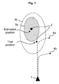
Fig. 1 serves to explain the use of a target tracking system according to the present invention when implemented in a collision avoidance system in an autonomous platform. However, it is to be understood that the present invention may be implemented in a wide variety of applications in which there is a need for tracking a target. InFig. 1 , anautonomous platform 1 is approaching atarget 2. - A target tracking system implemented in the
platform 1 may comprise a tracking filter. The tracking filter may be arranged to perform model-based target tracking. The outputs of the model-based target tracking may be, for example, the estimated state and its uncertainty parameters. The uncertainty parameters may be the covariance matrix of the estimated state. - In some applications, the uncertainty parameters, or the covariance matrix, are equally important as the estimated state, for example, in a collision avoidance system as demonstrated in
Fig. 1 . The collision avoidance system in theplatform 1 may use the uncertainty parameters in order to calculate an evasive manoeuvre. As shown in the scenario ofFig. 1 , the target tracking system in theplatform 1 may estimate the position of thetarget 2, and its uncertainty parameters, e.g. the covariance matrix, which defines an area ofuncertainty platform 1 may perform anevasive manoeuvre 4a (dashed arrow) that is based on the estimated area ofuncertainty 3a (lined area). This will result in anevasive manoeuvre 4a which may be dangerously close to a possible true position of thetarget 2. In a worst case, a collision may not be avoided. In addition, if the uncertainty parameters are overestimated, it may result in that the collision avoidance system of theplatform 1 performs unnecessary manoeuvres which may be interpreted as nuisance behaviour. - Therefore, a well-balanced estimation of the uncertainty parameters is desired. This will result in that the collision avoidance system of the
platform 1 may perform anevasive manoeuvre 4b (dotted arrow) that is based on the estimated area ofuncertainty 3b (dotted area). However, to achieve such a well-balanced estimation of the uncertainty parameters for both non-manoeuvring and manoeuvring targets is a difficult task that requires complex, advanced calculations, which puts a high computational load on the target tracking system. Furthermore, it should be noted such calculations does not guarantee that the target tracking system produces good estimates of the state of thetarget 2. - The present invention addresses the problems discussed above by providing a robust and simple target tracking system capable of producing reliable tracking data for both non-manoeuvring and manoeuvring targets. This is achieved by a target tracking system comprising a manoeuvre detection unit and output switch arranged to only forward trusted and reliable tracking data to the output of the target tracking system. Exemplary embodiments of the present invention are described below in reference to
Fig. 2-6 . -
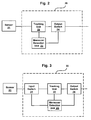
Fig. 2 shows atarget tracking system 20 according to an embodiment of the present invention. Thetarget tracking system 20 may comprise atracking unit 22, amanoeuvring detection unit 23 and anoutput switch 24. - A
sensor 21 is arranged to provide thetarget tracking system 20 with sensor measurement data. The sensor measurement data may comprise sensor measurements and uncertainty parameters for said sensor measurements. Thesensor 21 may be a passive sensor, such as, a camera, receiving antenna or the like. - The
tracking unit 22 may be a model-based tracking filter for tracking non-manoeuvring targets. For example, thetracking unit 22 may use a constant velocity model as a target model and a Kalman filter, a particle filter or the like for performing the tracking of the target. Thetracking unit 22 may be arranged to estimate the state of the target based on its model and received sensor measurement data from thesensor 21. The model may also be used for estimating states of a target that the sensor is not able to measure. Such estimated states may be referred to as observable states. An example is in the case of bearings-only tracking, that is, when using passive sensors measuring the bearing to the target, where the derivate of the bearing is an observable state. - The estimated state of the target may include, but are not limited to, for example, the bearing to the target, the bearing rate of the target, the range to the target, the range rate of the target, Time-To-Go (TTG), etc. TTG is the quote between range and the range's rate of change. The
tracking unit 22 may further be arranged to output the estimated state of the target and its uncertainty parameters, e.g. the covariance matrix of the estimated state, according to the model comprised therein. - If the sensor measurement data from the
sensor 21 does not include any uncertainty parameters, thetracking unit 22 may be arranged to retrieve suitable parameters from a series of received sensor measurements or may use predefined constants, which may be determined upon testing suitable filters for a specific application. - The
manoeuvre detection unit 23 is arranged to detect when a target that is being tracked by thetracking unit 22 performs a manoeuvre. Themanoeuvre detection unit 23 may be connected to or form a part of thetracking unit 22. Themanoeuvre detection unit 23 may also be arranged to send a manoeuvre detection alert to theoutput switch 24 as the target performs a manoeuvre. It may also be arranged to send a manoeuvre detection release to theoutput switch 24 in order to indicate that the target has stopped manoeuvring. - According to a preferred embodiment, the detection of a target manoeuvre by the
manoeuvre detection unit 23 may be performed by comparing the sensor measurement outputs from thesensor 21 with received estimated target states of the tracking filter in thetracking unit 22. Based on the resulting comparison signal, themanoeuvre detection unit 23 may detect when a target that is being tracked by the tracking filter in thetracking unit 22 performs a manoeuvre. Themanoeuvre detection unit 23 may be arranged to send a manoeuvre detection alert when, for example, the resulting comparison signal exceeds a specific limit or have been exceeding the specific limit for a predetermined period of time. This may be achieved, for example, by using cumulative sum calculations. Themanoeuvre detection unit 23 may also be arranged with multiple limits in order to, for example, be able to send different manoeuvre detection alerts for small or large target manoeuvres. - The
manoeuvre detection unit 23 may further be arranged to, upon detecting a target manoeuvre, indicate to thetracking unit 22 that the process noise for the tracking filter in thetracking unit 22 should be increased. Increasing the process noise will also increase the value of the uncertainties parameters, which reduces the risk of underestimating said uncertainty parameters and leads to an increased robustness against modelling errors in the tracking filter of thetracking unit 22. Additionally, this will also result in an increase of the gain of the tracking filter. - In the preferred embodiment above, since the resulting comparison signal is an indication of how well the sensor measurement outputs fits to the estimations of the tracking filter model in the
tracking unit 22, the increase of the process noise may be adapted to amount of received manoeuvre detection alerts. The process noise may thus be increased to a suitable level where manoeuvre detection alerts may no longer be received. - The
output switch 24 is arranged to continuously receive model estimations, that is, the estimated state of the target and its uncertainty parameters, from the tracking filter in thetracking unit 22. Theoutput switch 24 is also arranged to receive manoeuvre detection alerts from themanoeuvre detection unit 23. Theoutput switch 24 is further arranged to operate in at least two different output modes, and may switch between the at least two different output modes in response to receiving a manoeuvre detection alert from themanoeuvre detection unit 23. The outputs from theoutput switch 24 may be forwarded to any subsequent system in the platform in which thetarget tracking system 20 is implemented. - In the first output mode, the
output switch 24 forwards the received model estimations from the tracking filter in thetracking unit 22. This may be a default/start setting since targets are usually detected at long distances where target manoeuvres are hard to identify, and the initial values of the uncertainty parameters in the tracking filter in thetracking unit 22 often are large. In this first output mode, it is assumed that the model estimations outputted by thetracking unit 22 corresponds well with the true state of a non-manoeuvring target. - As a manoeuvre detection alert is received, the
output switch 24 may switch to a second output mode. In the second output mode, theoutput switch 24 only forwards the model estimations that are reliable and therefore may be trusted. This is because as the target performs a manoeuvre, some of the model estimations of the non-manoeuvring tracking filter in thetracking unit 22 are not valid. These model estimations may not be valid for a number of reasons as discussed above in the background. - For example, in the second output mode, the
output switch 24 may forward the bearing and bearing rate of the target, while blocking the range and range rate of the target. This is because the tracking filter in thetracking unit 22 may still be able to track the bearing and bearing rate of the manoeuvring target in a manner which corresponds well with the true state of the manoeuvring target. This is true in, for example, the case of the bearings-only tracking using passive sensors. However, other model estimates are likely to be erroneous as the target performs a manoeuvre. Therefore, the bearing and bearing rate of the manoeuvring target may be considered reliable and trusted model estimations. - In the second output mode, the
output switch 24 may further be arranged to increase the uncertainty parameters of the bearing and bearing rate of the manoeuvring target before outputting the trusted model estimations. This may be performed as a manoeuvre detection alert is received, and if the tracking filter in thetracking unit 22 tends to underestimate said uncertainty parameters. For example, theoutput switch 24 may be arranged to add a predetermined uncertainty to the uncertainty parameters as a target manoeuvre is detected by themanoeuvring detection unit 23. The predetermined uncertainty may be, for example, a constant uncertainty valule or an uncertainty value that slowly increases over time. The latter may be used because reasonably the uncertainty should increase over time when using an erroneous model. If amanoeuvre detection unit 23 capable of sending separate alerts for small or large manoeuvres is used, the predetermined uncertainty value may be selected based on if the manoeuvre is small or large. - Furthermore, the
output switch 24 may be arranged to receive a manoeuvre detection release from themanoeuvre detection unit 23. The manoeuvre detection release may indicate to theoutput switch 24 that the target has stopped manoeuvring. Theoutput switch 24 may then switch back to the first output mode, and again forward received model estimations from the tracking filter in thetracking unit 22. The tracking filter in thetracking unit 22 may then have to be re-started. As an alternative to the manoeuvre detection release, theoutput switch 24 may be arranged to switch back to the first output mode, when a manoeuvre detection alert has not been received for a predetermined period of time. -
Fig. 3 shows atarget tracking system 30 according to an embodiment of the present invention. In addition to atracking unit 22, amanoeuvring detection unit 23 and anoutput switch 24, as described in thetarget tracking system 20 in reference toFig. 2 , thetarget tracking system 30 comprises aninput switch 31. - The
input switch 31 may be arranged to increase the uncertainty parameters in the sensor output measurements of thesensor 21. This may be performed as a manoeuvre detection alert is received, and if thesensor 21 tends to underestimate said uncertainty parameters. Even if thesensor 21 does not tend to underestimate said uncertainty parameters, theinput switch 31 may be arranged to increase said uncertainty parameters if, for example, it is noted during the designing of thetracking system 30 that the tracking filter in thetracking unit 22 would produce more reliable values for the uncertainty parameters of the estimated target states, and achieve a better balance between sensor noise attenuation and model errors. -
Fig. 4 shows atarget tracking system 40 according to an embodiment of the present invention. In addition to atracking unit 22 and amanoeuvring detection unit 23, as described in thetarget tracking system 20 in reference toFig. 2 , thetarget tracking system 40 comprise asupplemental filter 41 and anoutput switch 44. - The
filter 41 may be arranged to receive and filter sensor measurement outputs from thesensor 21. Thefilter 41 may be a simple, non-model based filter, such as, for example, a low-pass filter. If the low-pass filter is combined with a differential filter in thefilter 41, thefilter 41 may also calculate derivates of the sensor measurements outputs. Thefilter 41 may thus provide, for example, the bearing and bearing rate of a target to theoutput switch 44. - The
output switch 44 is identical with theoutput switch 24, except that it may further be arranged to receive outputs from thefilter 41, and switch to and operate in a third output mode. In the third output mode, theoutput switch 44 only forwards the received outputs from thefilter 41. These filter outputs, for example, the bearing and bearing rate of a target, may be considered reliable measurements and may therefore be trusted. Note that preferably no uncertainty parameters of estimated target states are forwarded by theoutput switch 44 in this third output mode. However, the uncertainty parameters of sensor measurement outputs may be forwarded, as well as, the uncertainty parameters of the bearing rate and the bearing rate of change provided by thefilter 41, which may be analysed during the design phase in order to achieve a suitable parameter correction. - As the
output switch 44 receives a manoeuvre detection alert from themanoeuvre detection unit 23, it may be arranged to decide whether to switch to the second output mode or to the third output mode, that is, use the outputs from the tracking filter in thetracking unit 22 or from thefilter 41. This, however, requires a bit more logic to be included in theoutput switch 44. For example, if amanoeuvre detection unit 23 capable of sending separate alerts for small or large manoeuvres is used, theoutput switch 44 may be arranged to select the most suitable of the second and third output modes. The most suitable output mode may also be switched to in dependence of the requirements of the surrounding system in which thetarget tracking system 40 is implemented. - A further alternative is a fourth output mode where the
tracking unit 22 and thefilter 41 is bypassed and the sensor measurement outputs from thesensor 21 is directly sent to the output switch 44 (as shown by the dotted line inFig. 4 ). This, however, results in that only the measured states may be forwarded by theoutput switch 44 as reliable and trusted outputs. In the case of bearings-only tracking, the bearing of the target may be forwarded by theoutput switch 44 as a reliable and trusted output. An advantage with this alternative is that thefilter 41 does not have to be designed and implemented. -
Fig. 5 shows atarget tracking system 50 according to an embodiment of the present invention. In addition to atracking unit 22, amanoeuvring detection unit 23, afilter 41 and anoutput switch 44, as described in thetarget tracking system 40 in reference toFig. 4 , thetarget tracking system 50 comprise aninput switch 51. - The
input switch 51 is identical with theinput switch 31, except that it may further arranged to disconnect or block the input of thetracking unit 22 from the sensor measurement output of thesensor 21. In this way, theinput switch 51 may protect the tracking filter in thetracking unit 22 from bad or corrupt sensor measurement outputs from thesensor 21, and prevent the tracking filter from starting to diverge and becoming numerically unstable. Theinput switch 51 may disconnect or block the input of thetracking unit 22 in response to receiving a manoeuvre detection alert from themanoeuvre detection unit 23. - As the previously described
input switch 31, theinput switch 51 may also be arranged to increase the uncertainty parameters in the sensor output measurements of thesensor 21. -
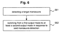
Fig. 6 shows flowchart illustrating a method according to an embodiment of the present invention. - In step S61, a target manoeuvre is detected. The
manoeuvre detection unit 23 may compare the sensor measurement outputs from thesensor 21 with the estimated states of the tracking filter in thetracking unit 22. Based on said comparison themanoeuvre detection unit 23 may detect when a target that is being tracked by the tracking filter in thetracking unit 22 performs a manoeuvre. - In step S62, a switch from a first output mode to at least a second output mode is performed in response to the target manoeuvre detection in step S61. The
manoeuvre detection unit 23 may send a manoeuvre detection alert to a trackingfilter 22, anoutput switch input switch 31. In response to receiving the manoeuvre detection alert, theoutput switch tracking unit 22 are forwarded, and a second, third or fourth output mode, in which only reliable outputs are forwarded. - The present invention described in the exemplary embodiments above may be used in all kinds of tracking, but may be particularly beneficial in situations such as, for example, where manoeuvring targets are common and result in a degradation in the performance of the non-manoeuvring tracking filter, or where surrounding applications require that the estimated errors are reflected well in the uncertainty parameters of the tracking filter outputted by the target tracking system.
- The
target tracking system tracking unit 22, themanoeuvring detection unit 23, theoutput switch 24, the inputs switch 31 and thefilter 41, may also be implemented as software algorithms in a computer program product or as dedicated computer hardware. - The description above is of the best mode presently contemplated for practising the present invention. The description is not intended to be taken in a limiting sense, but is made merely for the purpose of describing the general principles of the invention.
- The scope of the present invention should only be ascertained with reference to the issued claims.
Claims (14)
- A target tracking system (20; 30; 40; 50) comprising- tracking means (22) arranged to perform model-based tracking of a target (2) based on received measurements from a passive sensor (21),- detection means (23) arranged to detect when a target (2) performs a manoeuvre;- output switching means (24) arranged to receive manoeuvre detection alerts from the detection means (23) and to switch between first and second output modes in response to the received detection alerts from said detection means (23),characterized in that the output switching means are arranged to continuously receive model estimations from the tracking means (22), wherein in the first output mode the output switching means are arranged to forward the received model estimations corresponding with the true state of a non-manoeuvring target, and wherein in the at least second output mode the switch is arranged to only forward reliable outputs corresponding with the true state of a manoeuvring target, and wherein in the first output mode the switching means are arranged to forward bearing and bearing rate and range and range rate and wherein in the at least second output mode the bearing and bearing rate of the target is forwarded while range and range rate is blocked.
- A target tracking system (20; 30; 40; 50) according to claim 1, wherein said reliable outputs are a selection of said model estimations received from said tracking means (22), outputs received from a filter (41) and/or outputs received directly from the sensor (21).
- A target tracking system (20; 30; 40; 50) according to any one of the claims 1-2, wherein said tracking means (22) is arranged to increase the process noise of the model-based tracking in response to information indicating the detection of a target manoeuvre being received from said detection means (23).
- A target tracking system (20; 30; 40; 50) according to any one of the claims 1-3, further comprising:input switching means (31; 51) arranged to disconnect an input of the tracking means (22) from the measurement output of the sensor (21), and/or increase uncertainty parameters in the sensor output measurements.
- A target tracking system (20; 30; 40; 50) according to any one of the claims 1-4, wherein said output switching means (24) is arranged to increase uncertainty parameters in the model estimations received from said tracking means (22).
- A target tracking system (20; 30; 40; 50) according to any one of the claims 2-5, wherein said filter (41) is, non-model based filters, such as a low-pass filter and/or a differential filter.
- A target tracking system (20; 30; 40; 50) according to any one of the claims 1-6, wherein said sensor (21) is a camera or an antenna.
- A collision avoidance system comprising a target tracking system according to any one of the claims 1-7.
- A method for tracking a target (2) by performing model-based tracking of a target using tracking means based on received measurements from a passive sensor (21), comprising the step of:- detecting as the target (2) performs a manoeuvre;- continuously receiving model estimations from the tracking means,- forwarding in a first output mode the received model estimations corresponding with the true state of a non-maneuvering target,- receiving maneuver detection alerts based on the detection,- switching in response to said detection, from the first output mode to a second output modecharacterized in that in the first mode bearing and bearing rate and range and range rate are forwarded and in that in the second output mode only reliable outputs are forwarded corresponding with the true state of a manoeuvring target, wherein bearing and bearing rate of the target is forwarded while range and range rate is blocked.
- A method according to claim 9, further comprising the step of:receiving said reliable outputs as a selection of said model estimations, as filter outputs (41) and/or as sensor outputs (21).
- A method according to claims 9 or 10, further comprising the step of:increasing the process noise of the model-based tracking in response to information indicating a target manoeuvre.
- A method according to any one of the claims 9-11, further comprising the step of:disconnecting the input of a tracking means (22) from the measurement output of said sensor (21); and/orincreasing the uncertainty parameters in the sensor output measurements and/or in the model estimations.
- A computer program product for use in a target tracking system (20; 30; 40; 50) performing model-based tracking of a target using tracking means, said computer program product comprising computer readable code means, which when run in the target tracking system (20; 30; 40; 50) causes said target tracking system (20; 30; 40; 50) to perform the steps of:- detecting as the target (2) performs a manoeuvre;- continuously receiving model estimations from the tracking means,- forwarding in a first output mode the received model estimations corresponding with the true state of a non-maneuvering,- receiving maneuver detection alerts based on the detection,- switching in response to said detection, from the first output mode to a second output mode,characterized in that in the first mode bearing and bearing rate and range and range rate are forwarded and in that in the second output mode only reliable outputs are forwarded corresponding with the true state of a manoeuvring target, wherein bearing and bearing rate of the target is forwarded while range and range rate is blocked
- A computer program product for use in a target tracking system (20; 30; 40; 50) according to claim 13, wherein said code means is stored on a readable storage medium.
Priority Applications (5)
| Application Number | Priority Date | Filing Date | Title |
|---|---|---|---|
| EP08163157A EP2159595B1 (en) | 2008-08-28 | 2008-08-28 | A target tracking system and a method for tracking a target |
| ES08163157T ES2407830T3 (en) | 2008-08-28 | 2008-08-28 | A goal tracking system and a procedure for tracking a goal |
| BRPI0917842-2A BRPI0917842B1 (en) | 2008-08-28 | 2009-08-13 | target tracking system and method for tracking a target |
| US13/061,200 US9213087B2 (en) | 2008-08-28 | 2009-08-13 | Target tracking system and a method for tracking a target |
| PCT/SE2009/050934 WO2010024752A1 (en) | 2008-08-28 | 2009-08-13 | A target tracking system and a method for tracking a target |
Applications Claiming Priority (1)
| Application Number | Priority Date | Filing Date | Title |
|---|---|---|---|
| EP08163157A EP2159595B1 (en) | 2008-08-28 | 2008-08-28 | A target tracking system and a method for tracking a target |
Publications (2)
| Publication Number | Publication Date |
|---|---|
| EP2159595A1 EP2159595A1 (en) | 2010-03-03 |
| EP2159595B1 true EP2159595B1 (en) | 2013-03-20 |
Family
ID=40210523
Family Applications (1)
| Application Number | Title | Priority Date | Filing Date |
|---|---|---|---|
| EP08163157A Active EP2159595B1 (en) | 2008-08-28 | 2008-08-28 | A target tracking system and a method for tracking a target |
Country Status (5)
| Country | Link |
|---|---|
| US (1) | US9213087B2 (en) |
| EP (1) | EP2159595B1 (en) |
| BR (1) | BRPI0917842B1 (en) |
| ES (1) | ES2407830T3 (en) |
| WO (1) | WO2010024752A1 (en) |
Families Citing this family (3)
| Publication number | Priority date | Publication date | Assignee | Title |
|---|---|---|---|---|
| ES2407830T3 (en) * | 2008-08-28 | 2013-06-14 | Saab Ab | A goal tracking system and a procedure for tracking a goal |
| US9552648B1 (en) * | 2012-01-23 | 2017-01-24 | Hrl Laboratories, Llc | Object tracking with integrated motion-based object detection (MogS) and enhanced kalman-type filtering |
| RU2560524C1 (en) * | 2014-06-17 | 2015-08-20 | Николай Леонтьевич Бузинский | Direction determination device |
Family Cites Families (26)
| Publication number | Priority date | Publication date | Assignee | Title |
|---|---|---|---|---|
| US3737902A (en) * | 1970-08-19 | 1973-06-05 | State Street Bank & Trust Co | Collision avoidance system providing a vector signal representative of the distance and bearing between a prime vehicle and target object at a predicted closest point of approach therebetween |
| JP2749727B2 (en) | 1991-03-08 | 1998-05-13 | 三菱電機株式会社 | Route prediction device |
| US5214433A (en) | 1992-06-17 | 1993-05-25 | The United States Of America As Represented By The Secretary Of The Navy | Two-stage target tracking system and method |
| US5390133A (en) * | 1992-09-30 | 1995-02-14 | Martin Marietta Corporation | Image processor for target detection and tracking |
| RU2048684C1 (en) * | 1993-03-27 | 1995-11-20 | Войсковая часть 99727 | Method for tracking maneuvering aerial target |
| DE4421435C2 (en) * | 1994-06-21 | 1996-05-09 | Stn Atlas Elektronik Gmbh | Procedure for guiding an underwater defense weapon |
| US5631653A (en) * | 1996-04-25 | 1997-05-20 | Hughes Electronics | Dynamic inertial coordinate system maneuver detector and processing method |
| US6204784B1 (en) * | 2000-04-21 | 2001-03-20 | Raytheon Company | Multiple analog to digital converter clock phase alignment technique using varactor diodes |
| US6482064B1 (en) * | 2000-08-02 | 2002-11-19 | Interlego Ag | Electronic toy system and an electronic ball |
| SE518066C2 (en) | 2000-12-21 | 2002-08-20 | Ericsson Telefon Ab L M | Distance measurement to a moving object using a directional measuring sensor |
| DE60230488D1 (en) * | 2001-03-16 | 2009-02-05 | Haptica Ltd | VEHICLE GUIDANCE AND SYSTEM |
| SG101444A1 (en) * | 2001-04-20 | 2004-01-30 | Singapore Tech Aerospace Ltd | A maneuvering target tracking method via modifying the interacting multiple model (imm) and the interacting acceleration compensation (iac) algorithms |
| US6822583B2 (en) * | 2002-08-12 | 2004-11-23 | Bae Systems Information And Electronic Systems Integration Inc. | Method for passive “360-degree coverage” tactical fighter target tracking incorporating adaptive pilot maneuver cue processing |
| US7239719B2 (en) * | 2003-08-22 | 2007-07-03 | Bbn Technologies Corp. | Automatic target detection and motion analysis from image data |
| US8144931B1 (en) * | 2004-04-22 | 2012-03-27 | Hartman Richard L | Real time correlator system and method |
| GB0504889D0 (en) | 2005-03-08 | 2005-08-17 | Advanced System Architecture L | Management of tracking models suitable for demanding defence scenarios |
| US20060236721A1 (en) * | 2005-04-20 | 2006-10-26 | United States Of America As Represented By The Dept Of The Army | Method of manufacture for a compound eye |
| WO2008051240A2 (en) * | 2005-11-18 | 2008-05-02 | Georgia Tech Research Corporation | System, apparatus and methods for augmenting filter with adaptive element |
| WO2007105792A1 (en) * | 2006-03-15 | 2007-09-20 | Omron Corporation | Monitor and monitoring method, controller and control method, and program |
| US20080065328A1 (en) * | 2006-09-08 | 2008-03-13 | Andreas Eidehall | Method and system for collision avoidance |
| EP1986016A1 (en) * | 2007-04-25 | 2008-10-29 | Saab Ab | Device and method for controlling a satellite tracking antenna |
| US8229163B2 (en) * | 2007-08-22 | 2012-07-24 | American Gnc Corporation | 4D GIS based virtual reality for moving target prediction |
| DE102008003205A1 (en) * | 2008-01-04 | 2009-07-09 | Wabco Gmbh | Device, method and computer program for collision avoidance or for reducing the collision severity as a result of a collision for vehicles, in particular commercial vehicles |
| ES2407830T3 (en) * | 2008-08-28 | 2013-06-14 | Saab Ab | A goal tracking system and a procedure for tracking a goal |
| EP2200006B1 (en) * | 2008-12-19 | 2013-03-13 | Saab Ab | Method and arrangement for estimating at least one parameter of an intruder |
| US20120092329A1 (en) * | 2010-10-13 | 2012-04-19 | Qualcomm Incorporated | Text-based 3d augmented reality |
-
2008
- 2008-08-28 ES ES08163157T patent/ES2407830T3/en active Active
- 2008-08-28 EP EP08163157A patent/EP2159595B1/en active Active
-
2009
- 2009-08-13 WO PCT/SE2009/050934 patent/WO2010024752A1/en not_active Ceased
- 2009-08-13 US US13/061,200 patent/US9213087B2/en active Active
- 2009-08-13 BR BRPI0917842-2A patent/BRPI0917842B1/en active IP Right Grant
Also Published As
| Publication number | Publication date |
|---|---|
| ES2407830T3 (en) | 2013-06-14 |
| US9213087B2 (en) | 2015-12-15 |
| US20110200228A1 (en) | 2011-08-18 |
| WO2010024752A1 (en) | 2010-03-04 |
| EP2159595A1 (en) | 2010-03-03 |
| BRPI0917842A2 (en) | 2015-11-24 |
| BRPI0917842B1 (en) | 2021-02-23 |
Similar Documents
| Publication | Publication Date | Title |
|---|---|---|
| EP1610152B1 (en) | Tracking of a moving object for a self-defence system | |
| JP6239664B2 (en) | Ambient environment estimation apparatus and ambient environment estimation method | |
| CN106560725B (en) | Automated vehicle radar system for determining yaw rate of a target vehicle | |
| CN109884586A (en) | Ultra-bandwidth-based UAV positioning method, device, system and storage medium | |
| CN111226127A (en) | Radar horizontal installation angle correction method, radar and vehicle | |
| CN108535720A (en) | Adaptive process noise for improved Kalman filtering target following describes | |
| KR102126670B1 (en) | Apparatus and method for tracking objects with optimizing region of interest | |
| KR101813790B1 (en) | Apparatus and Method for multi-sensor information fusion based on feature information | |
| EP2159595B1 (en) | A target tracking system and a method for tracking a target | |
| US11555913B2 (en) | Object recognition device and object recognition method | |
| CN112379350A (en) | Intelligent vehicle millimeter wave radar multi-target tracking method, device and equipment | |
| CN116184386A (en) | A target tracking method, device and storage medium | |
| Floudas et al. | A survey of filtering techniques for vehicle tracking by radar equipped automotive platforms | |
| Saho | Fundamental properties and optimal gains of a steady state velocity measured α-β tracking filter | |
| KR102211844B1 (en) | Method and apparatus for estimating behind wall Multi-target in an IR-UWB Radar system | |
| JP5725701B2 (en) | Tracking device | |
| CN112781591A (en) | Robot positioning method and device, computer readable storage medium and robot | |
| Ikram et al. | A new data association method for 3-D object tracking in automotive applications | |
| CN119283895B (en) | Intersection oncoming vehicle azimuth and track determining method and related equipment | |
| EP4350384A1 (en) | Radar-based system in a vehicle and method for driver assistance or automated driving | |
| JP7491065B2 (en) | State estimation device, state estimation method, and state estimation program | |
| US20160116597A1 (en) | Apparatus for receiving navigation signal and operating method of the same | |
| JP3424626B2 (en) | Moving object collision prediction device | |
| WO2024158470A1 (en) | State estimation of a target using sensor measurements | |
| JP6334305B2 (en) | Signal processing device |
Legal Events
| Date | Code | Title | Description |
|---|---|---|---|
| PUAI | Public reference made under article 153(3) epc to a published international application that has entered the european phase |
Free format text: ORIGINAL CODE: 0009012 |
|
| AK | Designated contracting states |
Kind code of ref document: A1 Designated state(s): AT BE BG CH CY CZ DE DK EE ES FI FR GB GR HR HU IE IS IT LI LT LU LV MC MT NL NO PL PT RO SE SI SK TR |
|
| AX | Request for extension of the european patent |
Extension state: AL BA MK RS |
|
| 17P | Request for examination filed |
Effective date: 20100804 |
|
| 17Q | First examination report despatched |
Effective date: 20100827 |
|
| AKX | Designation fees paid |
Designated state(s): AT BE BG CH CY CZ DE DK EE ES FI FR GB GR HR HU IE IS IT LI LT LU LV MC MT NL NO PL PT RO SE SI SK TR |
|
| GRAP | Despatch of communication of intention to grant a patent |
Free format text: ORIGINAL CODE: EPIDOSNIGR1 |
|
| GRAS | Grant fee paid |
Free format text: ORIGINAL CODE: EPIDOSNIGR3 |
|
| GRAA | (expected) grant |
Free format text: ORIGINAL CODE: 0009210 |
|
| AK | Designated contracting states |
Kind code of ref document: B1 Designated state(s): AT BE BG CH CY CZ DE DK EE ES FI FR GB GR HR HU IE IS IT LI LT LU LV MC MT NL NO PL PT RO SE SI SK TR |
|
| REG | Reference to a national code |
Ref country code: GB Ref legal event code: FG4D |
|
| RIN1 | Information on inventor provided before grant (corrected) |
Inventor name: ERLANDSSON, TINA |
|
| REG | Reference to a national code |
Ref country code: CH Ref legal event code: EP |
|
| REG | Reference to a national code |
Ref country code: IE Ref legal event code: FG4D |
|
| REG | Reference to a national code |
Ref country code: AT Ref legal event code: REF Ref document number: 602390 Country of ref document: AT Kind code of ref document: T Effective date: 20130415 |
|
| REG | Reference to a national code |
Ref country code: DE Ref legal event code: R096 Ref document number: 602008022991 Country of ref document: DE Effective date: 20130516 |
|
| REG | Reference to a national code |
Ref country code: ES Ref legal event code: FG2A Ref document number: 2407830 Country of ref document: ES Kind code of ref document: T3 Effective date: 20130614 |
|
| PG25 | Lapsed in a contracting state [announced via postgrant information from national office to epo] |
Ref country code: BG Free format text: LAPSE BECAUSE OF FAILURE TO SUBMIT A TRANSLATION OF THE DESCRIPTION OR TO PAY THE FEE WITHIN THE PRESCRIBED TIME-LIMIT Effective date: 20130620 Ref country code: SE Free format text: LAPSE BECAUSE OF FAILURE TO SUBMIT A TRANSLATION OF THE DESCRIPTION OR TO PAY THE FEE WITHIN THE PRESCRIBED TIME-LIMIT Effective date: 20130320 Ref country code: NO Free format text: LAPSE BECAUSE OF FAILURE TO SUBMIT A TRANSLATION OF THE DESCRIPTION OR TO PAY THE FEE WITHIN THE PRESCRIBED TIME-LIMIT Effective date: 20130620 Ref country code: LT Free format text: LAPSE BECAUSE OF FAILURE TO SUBMIT A TRANSLATION OF THE DESCRIPTION OR TO PAY THE FEE WITHIN THE PRESCRIBED TIME-LIMIT Effective date: 20130320 |
|
| REG | Reference to a national code |
Ref country code: LT Ref legal event code: MG4D |
|
| PG25 | Lapsed in a contracting state [announced via postgrant information from national office to epo] |
Ref country code: GR Free format text: LAPSE BECAUSE OF FAILURE TO SUBMIT A TRANSLATION OF THE DESCRIPTION OR TO PAY THE FEE WITHIN THE PRESCRIBED TIME-LIMIT Effective date: 20130621 Ref country code: SI Free format text: LAPSE BECAUSE OF FAILURE TO SUBMIT A TRANSLATION OF THE DESCRIPTION OR TO PAY THE FEE WITHIN THE PRESCRIBED TIME-LIMIT Effective date: 20130320 Ref country code: FI Free format text: LAPSE BECAUSE OF FAILURE TO SUBMIT A TRANSLATION OF THE DESCRIPTION OR TO PAY THE FEE WITHIN THE PRESCRIBED TIME-LIMIT Effective date: 20130320 Ref country code: LV Free format text: LAPSE BECAUSE OF FAILURE TO SUBMIT A TRANSLATION OF THE DESCRIPTION OR TO PAY THE FEE WITHIN THE PRESCRIBED TIME-LIMIT Effective date: 20130320 |
|
| REG | Reference to a national code |
Ref country code: NL Ref legal event code: VDEP Effective date: 20130320 |
|
| PG25 | Lapsed in a contracting state [announced via postgrant information from national office to epo] |
Ref country code: HR Free format text: LAPSE BECAUSE OF FAILURE TO SUBMIT A TRANSLATION OF THE DESCRIPTION OR TO PAY THE FEE WITHIN THE PRESCRIBED TIME-LIMIT Effective date: 20130320 Ref country code: BE Free format text: LAPSE BECAUSE OF FAILURE TO SUBMIT A TRANSLATION OF THE DESCRIPTION OR TO PAY THE FEE WITHIN THE PRESCRIBED TIME-LIMIT Effective date: 20130320 |
|
| PG25 | Lapsed in a contracting state [announced via postgrant information from national office to epo] |
Ref country code: IS Free format text: LAPSE BECAUSE OF FAILURE TO SUBMIT A TRANSLATION OF THE DESCRIPTION OR TO PAY THE FEE WITHIN THE PRESCRIBED TIME-LIMIT Effective date: 20130720 Ref country code: SK Free format text: LAPSE BECAUSE OF FAILURE TO SUBMIT A TRANSLATION OF THE DESCRIPTION OR TO PAY THE FEE WITHIN THE PRESCRIBED TIME-LIMIT Effective date: 20130320 Ref country code: NL Free format text: LAPSE BECAUSE OF FAILURE TO SUBMIT A TRANSLATION OF THE DESCRIPTION OR TO PAY THE FEE WITHIN THE PRESCRIBED TIME-LIMIT Effective date: 20130320 Ref country code: CZ Free format text: LAPSE BECAUSE OF FAILURE TO SUBMIT A TRANSLATION OF THE DESCRIPTION OR TO PAY THE FEE WITHIN THE PRESCRIBED TIME-LIMIT Effective date: 20130320 Ref country code: EE Free format text: LAPSE BECAUSE OF FAILURE TO SUBMIT A TRANSLATION OF THE DESCRIPTION OR TO PAY THE FEE WITHIN THE PRESCRIBED TIME-LIMIT Effective date: 20130320 Ref country code: PT Free format text: LAPSE BECAUSE OF FAILURE TO SUBMIT A TRANSLATION OF THE DESCRIPTION OR TO PAY THE FEE WITHIN THE PRESCRIBED TIME-LIMIT Effective date: 20130722 Ref country code: RO Free format text: LAPSE BECAUSE OF FAILURE TO SUBMIT A TRANSLATION OF THE DESCRIPTION OR TO PAY THE FEE WITHIN THE PRESCRIBED TIME-LIMIT Effective date: 20130320 |
|
| PG25 | Lapsed in a contracting state [announced via postgrant information from national office to epo] |
Ref country code: CY Free format text: LAPSE BECAUSE OF FAILURE TO SUBMIT A TRANSLATION OF THE DESCRIPTION OR TO PAY THE FEE WITHIN THE PRESCRIBED TIME-LIMIT Effective date: 20130320 Ref country code: PL Free format text: LAPSE BECAUSE OF FAILURE TO SUBMIT A TRANSLATION OF THE DESCRIPTION OR TO PAY THE FEE WITHIN THE PRESCRIBED TIME-LIMIT Effective date: 20130320 |
|
| PLBE | No opposition filed within time limit |
Free format text: ORIGINAL CODE: 0009261 |
|
| STAA | Information on the status of an ep patent application or granted ep patent |
Free format text: STATUS: NO OPPOSITION FILED WITHIN TIME LIMIT |
|
| PG25 | Lapsed in a contracting state [announced via postgrant information from national office to epo] |
Ref country code: DK Free format text: LAPSE BECAUSE OF FAILURE TO SUBMIT A TRANSLATION OF THE DESCRIPTION OR TO PAY THE FEE WITHIN THE PRESCRIBED TIME-LIMIT Effective date: 20130320 |
|
| 26N | No opposition filed |
Effective date: 20140102 |
|
| REG | Reference to a national code |
Ref country code: CH Ref legal event code: PL |
|
| REG | Reference to a national code |
Ref country code: DE Ref legal event code: R097 Ref document number: 602008022991 Country of ref document: DE Effective date: 20140102 |
|
| PG25 | Lapsed in a contracting state [announced via postgrant information from national office to epo] |
Ref country code: LI Free format text: LAPSE BECAUSE OF NON-PAYMENT OF DUE FEES Effective date: 20130831 Ref country code: MC Free format text: LAPSE BECAUSE OF FAILURE TO SUBMIT A TRANSLATION OF THE DESCRIPTION OR TO PAY THE FEE WITHIN THE PRESCRIBED TIME-LIMIT Effective date: 20130320 Ref country code: CH Free format text: LAPSE BECAUSE OF NON-PAYMENT OF DUE FEES Effective date: 20130831 |
|
| REG | Reference to a national code |
Ref country code: IE Ref legal event code: MM4A |
|
| PG25 | Lapsed in a contracting state [announced via postgrant information from national office to epo] |
Ref country code: IE Free format text: LAPSE BECAUSE OF NON-PAYMENT OF DUE FEES Effective date: 20130828 |
|
| PG25 | Lapsed in a contracting state [announced via postgrant information from national office to epo] |
Ref country code: MT Free format text: LAPSE BECAUSE OF FAILURE TO SUBMIT A TRANSLATION OF THE DESCRIPTION OR TO PAY THE FEE WITHIN THE PRESCRIBED TIME-LIMIT Effective date: 20130320 Ref country code: TR Free format text: LAPSE BECAUSE OF FAILURE TO SUBMIT A TRANSLATION OF THE DESCRIPTION OR TO PAY THE FEE WITHIN THE PRESCRIBED TIME-LIMIT Effective date: 20130320 |
|
| PG25 | Lapsed in a contracting state [announced via postgrant information from national office to epo] |
Ref country code: LU Free format text: LAPSE BECAUSE OF NON-PAYMENT OF DUE FEES Effective date: 20130828 Ref country code: HU Free format text: LAPSE BECAUSE OF FAILURE TO SUBMIT A TRANSLATION OF THE DESCRIPTION OR TO PAY THE FEE WITHIN THE PRESCRIBED TIME-LIMIT; INVALID AB INITIO Effective date: 20080828 |
|
| REG | Reference to a national code |
Ref country code: FR Ref legal event code: PLFP Year of fee payment: 9 |
|
| REG | Reference to a national code |
Ref country code: FR Ref legal event code: PLFP Year of fee payment: 10 |
|
| REG | Reference to a national code |
Ref country code: FR Ref legal event code: PLFP Year of fee payment: 11 |
|
| PGFP | Annual fee paid to national office [announced via postgrant information from national office to epo] |
Ref country code: ES Payment date: 20190906 Year of fee payment: 12 Ref country code: IT Payment date: 20190822 Year of fee payment: 12 |
|
| PGFP | Annual fee paid to national office [announced via postgrant information from national office to epo] |
Ref country code: AT Payment date: 20190821 Year of fee payment: 12 |
|
| REG | Reference to a national code |
Ref country code: AT Ref legal event code: MM01 Ref document number: 602390 Country of ref document: AT Kind code of ref document: T Effective date: 20200828 |
|
| PG25 | Lapsed in a contracting state [announced via postgrant information from national office to epo] |
Ref country code: AT Free format text: LAPSE BECAUSE OF NON-PAYMENT OF DUE FEES Effective date: 20200828 |
|
| PG25 | Lapsed in a contracting state [announced via postgrant information from national office to epo] |
Ref country code: IT Free format text: LAPSE BECAUSE OF NON-PAYMENT OF DUE FEES Effective date: 20200828 |
|
| REG | Reference to a national code |
Ref country code: ES Ref legal event code: FD2A Effective date: 20220110 |
|
| PG25 | Lapsed in a contracting state [announced via postgrant information from national office to epo] |
Ref country code: ES Free format text: LAPSE BECAUSE OF NON-PAYMENT OF DUE FEES Effective date: 20200829 |
|
| PGFP | Annual fee paid to national office [announced via postgrant information from national office to epo] |
Ref country code: GB Payment date: 20250616 Year of fee payment: 18 |
|
| PGFP | Annual fee paid to national office [announced via postgrant information from national office to epo] |
Ref country code: FR Payment date: 20250618 Year of fee payment: 18 |
|
| PGFP | Annual fee paid to national office [announced via postgrant information from national office to epo] |
Ref country code: DE Payment date: 20250714 Year of fee payment: 18 |