EP2159426A2 - Random pitch impeller for fuel pump - Google Patents
Random pitch impeller for fuel pump Download PDFInfo
- Publication number
- EP2159426A2 EP2159426A2 EP09006698A EP09006698A EP2159426A2 EP 2159426 A2 EP2159426 A2 EP 2159426A2 EP 09006698 A EP09006698 A EP 09006698A EP 09006698 A EP09006698 A EP 09006698A EP 2159426 A2 EP2159426 A2 EP 2159426A2
- Authority
- EP
- European Patent Office
- Prior art keywords
- blades
- impeller
- incremental
- expression
- angles
- Prior art date
- Legal status (The legal status is an assumption and is not a legal conclusion. Google has not performed a legal analysis and makes no representation as to the accuracy of the status listed.)
- Granted
Links
Images


Classifications
-
- F—MECHANICAL ENGINEERING; LIGHTING; HEATING; WEAPONS; BLASTING
- F04—POSITIVE - DISPLACEMENT MACHINES FOR LIQUIDS; PUMPS FOR LIQUIDS OR ELASTIC FLUIDS
- F04D—NON-POSITIVE-DISPLACEMENT PUMPS
- F04D29/00—Details, component parts, or accessories
- F04D29/18—Rotors
- F04D29/22—Rotors specially for centrifugal pumps
- F04D29/24—Vanes
- F04D29/242—Geometry, shape
- F04D29/245—Geometry, shape for special effects
-
- F—MECHANICAL ENGINEERING; LIGHTING; HEATING; WEAPONS; BLASTING
- F04—POSITIVE - DISPLACEMENT MACHINES FOR LIQUIDS; PUMPS FOR LIQUIDS OR ELASTIC FLUIDS
- F04D—NON-POSITIVE-DISPLACEMENT PUMPS
- F04D5/00—Pumps with circumferential or transverse flow
- F04D5/002—Regenerative pumps
-
- F—MECHANICAL ENGINEERING; LIGHTING; HEATING; WEAPONS; BLASTING
- F04—POSITIVE - DISPLACEMENT MACHINES FOR LIQUIDS; PUMPS FOR LIQUIDS OR ELASTIC FLUIDS
- F04D—NON-POSITIVE-DISPLACEMENT PUMPS
- F04D29/00—Details, component parts, or accessories
- F04D29/18—Rotors
- F04D29/188—Rotors specially for regenerative pumps
-
- F—MECHANICAL ENGINEERING; LIGHTING; HEATING; WEAPONS; BLASTING
- F04—POSITIVE - DISPLACEMENT MACHINES FOR LIQUIDS; PUMPS FOR LIQUIDS OR ELASTIC FLUIDS
- F04D—NON-POSITIVE-DISPLACEMENT PUMPS
- F04D29/00—Details, component parts, or accessories
- F04D29/66—Combating cavitation, whirls, noise, vibration or the like; Balancing
- F04D29/669—Combating cavitation, whirls, noise, vibration or the like; Balancing especially adapted for liquid pumps
-
- F—MECHANICAL ENGINEERING; LIGHTING; HEATING; WEAPONS; BLASTING
- F05—INDEXING SCHEMES RELATING TO ENGINES OR PUMPS IN VARIOUS SUBCLASSES OF CLASSES F01-F04
- F05D—INDEXING SCHEME FOR ASPECTS RELATING TO NON-POSITIVE-DISPLACEMENT MACHINES OR ENGINES, GAS-TURBINES OR JET-PROPULSION PLANTS
- F05D2210/00—Working fluids
- F05D2210/10—Kind or type
- F05D2210/11—Kind or type liquid, i.e. incompressible
-
- F—MECHANICAL ENGINEERING; LIGHTING; HEATING; WEAPONS; BLASTING
- F05—INDEXING SCHEMES RELATING TO ENGINES OR PUMPS IN VARIOUS SUBCLASSES OF CLASSES F01-F04
- F05D—INDEXING SCHEME FOR ASPECTS RELATING TO NON-POSITIVE-DISPLACEMENT MACHINES OR ENGINES, GAS-TURBINES OR JET-PROPULSION PLANTS
- F05D2260/00—Function
- F05D2260/60—Fluid transfer
-
- Y—GENERAL TAGGING OF NEW TECHNOLOGICAL DEVELOPMENTS; GENERAL TAGGING OF CROSS-SECTIONAL TECHNOLOGIES SPANNING OVER SEVERAL SECTIONS OF THE IPC; TECHNICAL SUBJECTS COVERED BY FORMER USPC CROSS-REFERENCE ART COLLECTIONS [XRACs] AND DIGESTS
- Y10—TECHNICAL SUBJECTS COVERED BY FORMER USPC
- Y10S—TECHNICAL SUBJECTS COVERED BY FORMER USPC CROSS-REFERENCE ART COLLECTIONS [XRACs] AND DIGESTS
- Y10S415/00—Rotary kinetic fluid motors or pumps
-
- Y—GENERAL TAGGING OF NEW TECHNOLOGICAL DEVELOPMENTS; GENERAL TAGGING OF CROSS-SECTIONAL TECHNOLOGIES SPANNING OVER SEVERAL SECTIONS OF THE IPC; TECHNICAL SUBJECTS COVERED BY FORMER USPC CROSS-REFERENCE ART COLLECTIONS [XRACs] AND DIGESTS
- Y10—TECHNICAL SUBJECTS COVERED BY FORMER USPC
- Y10S—TECHNICAL SUBJECTS COVERED BY FORMER USPC CROSS-REFERENCE ART COLLECTIONS [XRACs] AND DIGESTS
- Y10S417/00—Pumps
Definitions
- the present invention relates to a random pitch impeller for a fuel pump, and more particularly, to a random pitch impeller for a fuel pump, in which blades of the impeller used for the fuel pump are arranged at random pitches, thereby reducing high-frequency noise generated by rotation of the impeller, and minimizing pulsation noise attributable to random intervals.
- This fuel pump is used in the fuel supply system of the internal combustion engine and draws or discharges fluid, particularly fuel, by means of rotation of a rotating member such as an impeller formed on a disc and having blades on the outer circumference thereof.
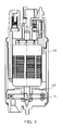
- the fuel pump includes a pump housing 102 having upper and lower housing parts, a disc-shaped impeller 101 rotatably installed in the pump housing 102, and a drive motor 103 rotating the impeller 101.
- the impeller of this fuel pump has numerous blades installed on the outer circumference thereof at uniform pitches, i.e. at equal intervals.
- each blade of the impeller passes through a partition, which is installed on the housing holding the rotating member, at constant time intervals.
- the partition is located adjacent to the blade between inlet and outlet of the fuel.
- a peak of sound pressure i.e. noise
- BPF blade passing frequency
- Japanese Patent Publication No. Hei 11(1999)-50990 discloses a fluid drawing and discharging apparatus, in which the intervals between the blades are disposed in a random manner, namely in an irregular manner.
- the fluid drawing and discharging apparatus disclosed in the patent document encounters a phenomenon that the blades lean to one side as illustrated in FIG. 2 because the blades are randomly disposed.
- the sound pressure peak a frequency of which is n times as high as a rotation-order frequency of the rotating member, occurs, or noise is increased within the frequency band of the sound pressure peak by resonance according to circumstances.
- the present invention has been made to solve the foregoing problems with the prior art, and therefore the present invention provides a random pitch impeller for a fuel pump, in which blades thereof are arranged at random pitches without being deflected in a specific section so as to reduce a sound pressure peak, and in which the random pitches of the blades are set on the basis of a periodic function so as to easily predict and adjust the arrangement of the blades.
- a random pitch impeller for a fuel pump capable of reducing noise through distribution of high-frequency peaks of the impeller, and minimizing pulsation noise (low-frequency peak) attributable to random intervals.
- the incremental angle has maximum and minimum values a difference of which satisfies an expression: 2 ⁇ ° ⁇ MAX - MIN ⁇ 6 ⁇ ° , where MAX is the maximum value, and MIN is the minimum value of the incremental angle.
- the impeller for a fuel pump arranges the blades at random pitches using a rand pitch function, prevents deflection of the blades by means of the term (-1) i of the random pitch function to thereby reduce a sound pressure peak, and creates the random pitches of the blades on the basis of a periodic function using both the distribution magnitude Am of the inter-blade interval (equally divided angle) and the factors P 1 and P 2 exerting an influence on a cycle so as to easily predict or adjust the arrangement of the blades.
- the impeller minimizes a low-frequency peak, pulsation noise, caused by the random intervals thereof and the resultant random flow.
- FIG. 1 illustrates the structure of a fuel pump
- FIG. 2 illustrates arrangement of blades of a random pitch impeller according to an embodiment of the present invention
- FIG. 3 is a graph showing results of comparing high-frequency peaks of a uniform pitch impeller with that of a random pitch impeller according to an embodiment of the present invention
- FIG. 4 is a graph showing a variation in pulsation noise
- FIG. 5 is a graph showing incremental angles of blades of a random pitch impeller according to an embodiment of the present invention.
- FIG. 6 is a graph showing an average of incremental angles of neighboring blades in a quarter section.
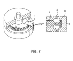
- FIG. 7 illustrates how a rotating flow is created from an impeller.
- Am is the distribution magnitude of the inter-blade interval (equally divided angle) (0 ⁇ Am ⁇ 360/N)
- P 1 and P 2 are the factors exerting much influence on the cycle (0 ⁇ P 1 ⁇ N, and 0 ⁇ P 2 ⁇ N).
- the impeller not only makes random pitch conditions of the same structure despite a change in the number of blades, but also makes the average of the incremental angles within a specific section similar to a grand average because the created functions comply with an oscillation (divergence) function due to the term (-1) i .
- FIG. 2 illustrates an impeller for a fuel pump which is designed by random pitch arrangement in accordance with an embodiment of the present invention. It can be seen that the neighboring blades 3 and 4 are arranged at intervals of a random angle rather than of a uniform angle.
- the impeller for a fuel pump can arrange the blades at random pitches by setting the incremental angle depending on Expression 1 above.
- the number of high-frequency peaks is obtained to an equivalent level in a specific section.
- the specific section refers to a section where a difference between the maximum and minimum values "MAX" and "MIN" of the incremental angle is less than 2.
- the difference between the maximum and minimum values of the incremental angle is preferably more than 2.
- Two kinds of noise measured from the uniform pitch impeller and the random pitch impeller under this condition are shown on a graph of FIG. 3 .
- the maximum value of the high-frequency peak of the uniform pitch impeller is about 53 dB(A)
- the maximum value of the high-frequency peak of the random pitch impeller of this embodiment is about 45 dB(A). It can be seen from this result that the high-frequency peaks of the random pitch impeller are distributed to reduce entire noise.
- the blades of the impeller are arranged at random pitches, it must be taken into consideration that an angle of minimizing low-frequency pulsation noise is selected.
- the uniform pitch impeller having the same inter-blade interval generates a small quantity of pulsation noise due to the same fluid passing area between the blades.
- the random pitch impeller having a different inter-blade interval generates a large quantity of pulsation noise because it is impossible to form a constant flow.
- the pulsation noise is increased, the low-frequency peak is increased. Particularly, the pulsation noise becomes more troublesome in proportion to a discharged flow rate of the impeller.
- FIG. 4 is a graph showing results of analyzing a variation of pulsation noise caused by a difference between the maximum and minimum values of the incremental angle.
- points are to designate the pulsation noise values shown in Table 1 below. It can be seen from FIG. 4 that, when the difference between the maximum and minimum values of the incremental angle is less than 6, the pulsation noise value can be controlled less than a predetermined level.
- the random pitch impeller of this embodiment preferably restricts the difference between the maximum and minimum values of the incremental angle as in Expression 2 below: 2 ⁇ ° ⁇ MAX - MIN ⁇ 6 ⁇ ° where MAX is the maximum value of the incremental value, and MIN is the minimum value of the incremental value.
- the embodiment presents that both the high-frequency peak and the low-frequency peak can be properly controlled through the difference between the maximum and minimum values of the incremental angle.
- the random pitch impeller controls the average of incremental angles in a specific section so as to have a value similar to the average of total blade angles such that the blades of the impeller can be arranged at unequal intervals to distribute high-frequency peaks, and simultaneously pulsation noise generated by the unequal intervals can be minimized.
- the average of the incremental angles in the specific section and the average of the total blade angles i.e. 360/N
- the average "AVG_SEC" of ten neighboring incremental angles is derived, the derived average must be similar to the average "AVG TOT" of the total blade angles, i.e. 360/N.
- FIG. 5 is a graph showing incremental angles of blades arranged at random pitches when the total number of blades is 41 in accordance with an embodiment of the present invention. It can be seen that the average of the incremental angles is about 8.8. At this time, the average "AVG_SEC" of the neighboring incremental angles in a section corresponding to 1/4 of the whole blades is preferably set to a range of ⁇ 0.5 on the basis of the average of the total incremental angles.
- FIG. 6 is a graph showing an average of incremental angles of neighboring blades in a quarter section when the total number of blades is 41. For example, when an x-axial value is 17, this value is an average of incremental angles of 8 th through 17 th blades. When an axial value is 1, this value is an average of incremental angle of 33 rd through 41 st and 1 st blades. As shown in FIG. 6 , the average of the incremental angles of the blades in each quarter section is set to an allowance range of ⁇ 0.5 on the basis of the average of the total incremental angles.
- the number of blades preferably has a range from 31 to 47, i.e. 31 ⁇ N ⁇ 47. If the number of blades preferably is equal to or less than 31, the interval between the neighboring blades of the impeller is increased. At this time, in the case of a low-capacity impeller having a relatively low rpm, the performance of the fuel pump is considerably reduced. In detail, if the speed of a rotating flow is increased in a channel, the capacity of raising pressure is improved as much, and thus the performance of the fuel pump is improved.
- FIG. 7 shows a process in which a rotating flow 15 is created as an outer circumferential wall 13 of an impeller 1 rotates.
- the symbol A designates a direction where fuel flows
- the symbol B represents a shape where the fuel passes.
- the number of blades of the impeller is preferably set under the use conditions of the fuel pump as in Expression 4 below: 31 ⁇ N ⁇ 47 where N is the total number of blades.
- the value of Am of Expression 1 is preferably set as follows: 1 ⁇ Am ⁇ 3.
- P 2 2 * P 1 .
- both the distribution magnitude Am of the inter-blade interval (i.e., equally divided angle) and the factors P 1 and P 2 exerting much influence on the cycle are controlled.
- the pitch conditions that are similar to the random pitch conditions and have predetermined intervals can be created, so that the arrangement of the blades can be easily predicted or adjusted.
- a sum of all the incremental angles may be more or less than 360°.
- the final incremental angle must be separately defined on the assumption that it should satisfy Expressions 2 and 3.
Landscapes
- Engineering & Computer Science (AREA)
- Mechanical Engineering (AREA)
- General Engineering & Computer Science (AREA)
- Physics & Mathematics (AREA)
- Geometry (AREA)
- Structures Of Non-Positive Displacement Pumps (AREA)
Abstract

where ΔθI is the incremental angle between the blades, N is the total number of blades (N=2, 3, 5, 7, 11, 13, 17,...), Am is the distribution magnitude of the inter-blade interval (equally divided angle) (0 < Am < 360/N), i is the order of the blade (i=1, 2, 3, ... , N), and P1 and P2 are the factors exerting an influence on the cycle (0 < P1 < N, and 0 ≤ P2 ≤ N). The incremental angle has maximum and minimum values a difference of which satisfies the expression: 2° ≤ MAX - MIN ≤ 6°, where MAX is the maximum value, and MIN is the minimum value of the incremental angle.
Description
- This application claims the benefit of Korean Patent Application No.
2008-0084840 filed on Aug 29 2008 - The present invention relates to a random pitch impeller for a fuel pump, and more particularly, to a random pitch impeller for a fuel pump, in which blades of the impeller used for the fuel pump are arranged at random pitches, thereby reducing high-frequency noise generated by rotation of the impeller, and minimizing pulsation noise attributable to random intervals.
- There have been known various apparatuses for drawing and/or discharging fluid, one of which is a fuel pump. This fuel pump is used in the fuel supply system of the internal combustion engine and draws or discharges fluid, particularly fuel, by means of rotation of a rotating member such as an impeller formed on a disc and having blades on the outer circumference thereof.
- As illustrated in
FIG. 1 , the fuel pump includes apump housing 102 having upper and lower housing parts, a disc-shaped impeller 101 rotatably installed in thepump housing 102, and adrive motor 103 rotating theimpeller 101. - Generally, the impeller of this fuel pump has numerous blades installed on the outer circumference thereof at uniform pitches, i.e. at equal intervals. Thus, when the rotating member rotates, each blade of the impeller passes through a partition, which is installed on the housing holding the rotating member, at constant time intervals. At this time, the partition is located adjacent to the blade between inlet and outlet of the fuel. For this reason, a peak of sound pressure (i.e. noise) is created within a certain frequency band, i.e. a so-called blade passing frequency (BPF) band, corresponding to the number of blades (or the revolutions per minute (rpm) of the rotating member).
- In order to solve this problem, Japanese Patent Publication No.
Hei 11(1999)-50990 FIG. 2 because the blades are randomly disposed. - Further, as illustrated in
FIG. 3 , since the time intervals at which each blade passes through the partition adjacent to the blade are constant without a difference, the sound pressure peak, a frequency of which is n times as high as a rotation-order frequency of the rotating member, occurs, or noise is increased within the frequency band of the sound pressure peak by resonance according to circumstances. - In order to overcome this drawback, Korean Patent Application Publication No.
1999-23306 - However, these fluid drawing and discharging apparatuses control the blade arrangement on the basis of a random number, so that prediction and control of the blade arrangement are impossible.
- The present invention has been made to solve the foregoing problems with the prior art, and therefore the present invention provides a random pitch impeller for a fuel pump, in which blades thereof are arranged at random pitches without being deflected in a specific section so as to reduce a sound pressure peak, and in which the random pitches of the blades are set on the basis of a periodic function so as to easily predict and adjust the arrangement of the blades.
- There is provided a random pitch impeller for a fuel pump, capable of reducing noise through distribution of high-frequency peaks of the impeller, and minimizing pulsation noise (low-frequency peak) attributable to random intervals.
- According to an aspect of the invention, there is provided an impeller for a fuel pump, having a number of blades, wherein: the blades have an incremental angle set by an expression below:

where ΔθI is the incremental angle between the blades, N is the total number of blades (N=2, 3, 5, 7, 11, 13, 17, ...), Am is the distribution magnitude of the inter-blade interval (equally divided angle) (0 < Am < 360/N), i is the order of the blade (i=1, 2, 3, ... , N), and P1 and P2 are the factors exerting an influence on the cycle (0 < P1 < N, and 0 ≤ P2 ≤ N) ; and the incremental angle has maximum and minimum values a difference of which satisfies an expression:
where MAX is the maximum value, and MIN is the minimum value of the incremental angle. - According to embodiments of the present invention, the impeller for a fuel pump arranges the blades at random pitches using a rand pitch function, prevents deflection of the blades by means of the term (-1)i of the random pitch function to thereby reduce a sound pressure peak, and creates the random pitches of the blades on the basis of a periodic function using both the distribution magnitude Am of the inter-blade interval (equally divided angle) and the factors P1 and P2 exerting an influence on a cycle so as to easily predict or adjust the arrangement of the blades.
- Further, the impeller minimizes a low-frequency peak, pulsation noise, caused by the random intervals thereof and the resultant random flow.
- The above and other objects, features and other advantages of the present invention will be more clearly understood from the following detailed description taken in conjunction with the accompanying drawings, in which:
-
FIG. 1 illustrates the structure of a fuel pump; -
FIG. 2 illustrates arrangement of blades of a random pitch impeller according to an embodiment of the present invention; -
FIG. 3 is a graph showing results of comparing high-frequency peaks of a uniform pitch impeller with that of a random pitch impeller according to an embodiment of the present invention; -
FIG. 4 is a graph showing a variation in pulsation noise; -
FIG. 5 is a graph showing incremental angles of blades of a random pitch impeller according to an embodiment of the present invention; -
FIG. 6 is a graph showing an average of incremental angles of neighboring blades in a quarter section; and -
FIG. 7 illustrates how a rotating flow is created from an impeller. - The present invention will now be described more fully hereinafter with reference to the accompanying drawings, in which exemplary embodiments thereof are shown.
- According to an embodiment of the present invention, an impeller for a fuel pump sets an incremental angle, Δθi, between blades as in Expression 1 (called a random pitch function) below:

where N is the total number of blades and the prime number (N=2, 3, 5, 7, 11, 13, 17, ...), Am is the distribution magnitude of the inter-blade interval (equally divided angle) (0 < Am < 360/N), i is the order of the blade (i=1, 2, 3, ... , N), and P1 and P2 are the factors exerting much influence on the cycle (0 < P1 < N, and 0 ≤ P2 ≤ N). - With this random pitch function, the impeller not only makes random pitch conditions of the same structure despite a change in the number of blades, but also makes the average of the incremental angles within a specific section similar to a grand average because the created functions comply with an oscillation (divergence) function due to the term (-1)i.
-
FIG. 2 illustrates an impeller for a fuel pump which is designed by random pitch arrangement in accordance with an embodiment of the present invention. It can be seen that the neighboringblades - MAX Minus MIN VALUE
- According to an embodiment of the present invention, the impeller for a fuel pump can arrange the blades at random pitches by setting the incremental angle depending on
Expression 1 above. However, in comparison of a uniform pitch impeller having the same angles between the blades with the random pitch impeller of this embodiment, the number of high-frequency peaks is obtained to an equivalent level in a specific section. Here, the specific section refers to a section where a difference between the maximum and minimum values "MAX" and "MIN" of the incremental angle is less than 2. - Thus, the difference between the maximum and minimum values of the incremental angle is preferably more than 2. Two kinds of noise measured from the uniform pitch impeller and the random pitch impeller under this condition are shown on a graph of
FIG. 3 . On this graph, the maximum value of the high-frequency peak of the uniform pitch impeller is about 53 dB(A), while the maximum value of the high-frequency peak of the random pitch impeller of this embodiment is about 45 dB(A). It can be seen from this result that the high-frequency peaks of the random pitch impeller are distributed to reduce entire noise. - Further, when the blades of the impeller are arranged at random pitches, it must be taken into consideration that an angle of minimizing low-frequency pulsation noise is selected. When transferring fluid, the uniform pitch impeller having the same inter-blade interval generates a small quantity of pulsation noise due to the same fluid passing area between the blades. In contrast, the random pitch impeller having a different inter-blade interval generates a large quantity of pulsation noise because it is impossible to form a constant flow. When the pulsation noise is increased, the low-frequency peak is increased. Particularly, the pulsation noise becomes more troublesome in proportion to a discharged flow rate of the impeller.
- Thus, in the random pitch impeller of this embodiment, when the difference between the maximum and minimum values "MAX" and "MIN" of the incremental angle is less than 6, a value of this pulsation noise can be limited to a certain level (about 3 Kpa or less).
FIG. 4 is a graph showing results of analyzing a variation of pulsation noise caused by a difference between the maximum and minimum values of the incremental angle. Here, points are to designate the pulsation noise values shown in Table 1 below. It can be seen fromFIG. 4 that, when the difference between the maximum and minimum values of the incremental angle is less than 6, the pulsation noise value can be controlled less than a predetermined level. -
Table 1 MAX Minus MIN Value 0 4 5 4.7 6.1 8 Pulsation Noise Value(Kpa) 1.4 2.3 2.4 2.3 3.1 6.1 3 7 6 3 7 4 - In order to satisfy all the conditions considered above, the random pitch impeller of this embodiment preferably restricts the difference between the maximum and minimum values of the incremental angle as in
Expression 2 below:
where MAX is the maximum value of the incremental value, and MIN is the minimum value of the incremental value. - The embodiment presents that both the high-frequency peak and the low-frequency peak can be properly controlled through the difference between the maximum and minimum values of the incremental angle.
- Average of Incremental Angles in Specific Section
- According to an embodiment of the present invention, the random pitch impeller controls the average of incremental angles in a specific section so as to have a value similar to the average of total blade angles such that the blades of the impeller can be arranged at unequal intervals to distribute high-frequency peaks, and simultaneously pulsation noise generated by the unequal intervals can be minimized. Thus, the average of the incremental angles in the specific section and the average of the total blade angles (i.e. 360/N) are controlled so as to satisfy
Expression 3 below:
where "AVG_SEC" is the average of the incremental angles in the specific section, and "AVG_TOT" is the average of the total blade angles. - For example, it is assumed that the total number of blades is 41 (i.e. N=41). Here, when the specific section is set to 1/4 of the total number of blades, the number of blades of the specific section becomes 41/4 (=10.25). In detail, when the average "AVG_SEC" of ten neighboring incremental angles is derived, the derived average must be similar to the average "AVG TOT" of the total blade angles, i.e. 360/N. Here, the average of the total blade angles becomes 360/41 (=8.8).
-
FIG. 5 is a graph showing incremental angles of blades arranged at random pitches when the total number of blades is 41 in accordance with an embodiment of the present invention. It can be seen that the average of the incremental angles is about 8.8. At this time, the average "AVG_SEC" of the neighboring incremental angles in a section corresponding to 1/4 of the whole blades is preferably set to a range of ±0.5 on the basis of the average of the total incremental angles. -
FIG. 6 is a graph showing an average of incremental angles of neighboring blades in a quarter section when the total number of blades is 41. For example, when an x-axial value is 17, this value is an average of incremental angles of 8th through 17th blades. When an axial value is 1, this value is an average of incremental angle of 33rd through 41st and 1st blades. As shown inFIG. 6 , the average of the incremental angles of the blades in each quarter section is set to an allowance range of ±0.5 on the basis of the average of the total incremental angles. - Selection of Number of Blades
- In order to secure a value exercising an influence on performance such as a flow rate, electric current, rpm, etc. under the use conditions of the fuel pump, the number of blades preferably has a range from 31 to 47, i.e. 31 ≤ N ≤ 47. If the number of blades preferably is equal to or less than 31, the interval between the neighboring blades of the impeller is increased. At this time, in the case of a low-capacity impeller having a relatively low rpm, the performance of the fuel pump is considerably reduced. In detail, if the speed of a rotating flow is increased in a channel, the capacity of raising pressure is improved as much, and thus the performance of the fuel pump is improved. In contrast, if the interval between the neighboring blades of the impeller is increased, the speed of the rotating flow is reduced, and thus the performance of the fuel pump is reduced.
FIG. 7 shows a process in which arotating flow 15 is created as an outercircumferential wall 13 of animpeller 1 rotates. Here, the symbol A designates a direction where fuel flows, and the symbol B represents a shape where the fuel passes. - Further, if the number of blades exceeds 47, the interval between the neighboring blades of the impeller is reduced, and thus an area through which fluid can pass is reduced. As such, when transferring a high flow rate, the impeller is subjected to an increase in load, an increase in electric current, and a decrease in flow rate performance, so that the performance of the fuel pump is greatly reduced. Thus, the number of blades of the impeller is preferably set under the use conditions of the fuel pump as in
Expression 4 below:
where N is the total number of blades. - Conditions of Other Factors
- In order to satisfy all the conditions of
Expressions 1 through 4 as described above, the value of Am ofExpression 1 is preferably set as follows: 1 ≤ Am ≤ 3. InExpression 1, P1 = 1 or P1 = N-1. Further, P2 = 2 * P1. - In order to satisfy the conditions presented to
Expressions 1 through 4 above, both the distribution magnitude Am of the inter-blade interval (i.e., equally divided angle) and the factors P1 and P2 exerting much influence on the cycle are controlled. Thereby, the pitch conditions that are similar to the random pitch conditions and have predetermined intervals can be created, so that the arrangement of the blades can be easily predicted or adjusted. - Setting of Final Incremental Angle
- When the incremental angles between the blades are set on the basis of
Expression 1, a sum of all the incremental angles may be more or less than 360°. In this case, the final incremental angle must be separately defined on the assumption that it should satisfyExpressions 
where the final incremental angle must also meet the conditions ofExpressions - [0025] Further, the incremental angles created through
Expression 1 are preferably rounded only to the first decimal place. If the incremental angles are applied without limiting the decimal point, some numbers after the first decimal place are reflected on the angle between the neighboring blades and the angle of installation, a difference of the total sum occurs. As in the embodiment, in the case in which the total number of blades is 41 (N=41), the sum of the total incremental angles satisfies 360° when the incremental angles are limited to the first decimal place. - [0026] While the present invention has been described with reference to the particular illustrative embodiments and the accompanying drawings, it is not to be limited thereto. Accordingly, the foregoing embodiments can be suitably modified and altered, and such applications fall within the scope and spirit of the present invention that shall be defined by the appended claims.
Claims (7)
- An impeller for a fuel pump, having a number of blades, wherein:the blades have an incremental angle set by an expression below:where ΔθI is the incremental angle between the blades, N is the total number of blades (N=2, 3, 5, 7, 11, 13, 17, ...), Am is the distribution magnitude of the inter-blade interval (equally divided angle) (0 < Am < 360/N), i is the order of the blade (i=1, 2, 3, ... , N), and P1 and P2 are the factors exerting an influence on the cycle (0 < P1 < N, and 0 ≤ P2 ≤ N); and

the incremental angle has maximum and minimum values a difference of which satisfies an expression:
where MAX is the maximum value, and MIN is the minimum value of the incremental angle. - The impeller as set forth in claim 1, wherein the blades has a total number satisfying an expression: 31 ≤ N ≤ 47, where N is the total number.
- The impeller as set forth in claim 1, wherein the incremental angle and total blade angles satisfy an expression:

where AVG_SEC is an average of the incremental angles in a specific section, 360/N is total blade angles, and AVG_TOT is an average of the total blade angles. - The impeller as set forth in claim 3, wherein the specific section is a section corresponding to a quarter of the total blades.
- The impeller as set forth in claim 1, wherein the distribution magnitude, Am, satisfies an expression of 1 ≤ Am ≤ 3.
- The impeller as set forth in claim 1, wherein the factor, P1, satisfies one of expressions of P1=1 and P1=N-1, and the factor, P2, satisfies an expression of P2=2*P1.
- The impeller as set forth in claim 1, wherein, when a sum of all the incremental angles is not equal to 360°, the incremental angles satisfy an expression:

where Δθn is the final one of the incremental angles.
Applications Claiming Priority (1)
| Application Number | Priority Date | Filing Date | Title |
|---|---|---|---|
| KR1020080084840A KR100872294B1 (en) | 2008-08-29 | 2008-08-29 | Unequal Pitch Impeller for Fuel Pump |
Publications (3)
| Publication Number | Publication Date |
|---|---|
| EP2159426A2 true EP2159426A2 (en) | 2010-03-03 |
| EP2159426A3 EP2159426A3 (en) | 2015-03-11 |
| EP2159426B1 EP2159426B1 (en) | 2016-08-03 |
Family
ID=40371987
Family Applications (1)
| Application Number | Title | Priority Date | Filing Date |
|---|---|---|---|
| EP09006698.6A Not-in-force EP2159426B1 (en) | 2008-08-29 | 2009-05-19 | Random pitch impeller for fuel pump |
Country Status (4)
| Country | Link |
|---|---|
| US (1) | US8092186B2 (en) |
| EP (1) | EP2159426B1 (en) |
| JP (1) | JP5001975B2 (en) |
| KR (1) | KR100872294B1 (en) |
Cited By (1)
| Publication number | Priority date | Publication date | Assignee | Title |
|---|---|---|---|---|
| DE112015005494B4 (en) | 2014-12-04 | 2023-05-25 | Korea Institute Of Industrial Technology | Irregular pitch regenerative blower machine and design optimization method therefor |
Families Citing this family (4)
| Publication number | Priority date | Publication date | Assignee | Title |
|---|---|---|---|---|
| US9249806B2 (en) | 2011-02-04 | 2016-02-02 | Ti Group Automotive Systems, L.L.C. | Impeller and fluid pump |
| JP6659911B2 (en) * | 2017-03-13 | 2020-03-04 | 株式会社ミツバ | Impeller |
| JP7363328B2 (en) | 2019-10-09 | 2023-10-18 | ニデック株式会社 | Impeller and axial fan |
| KR102298877B1 (en) | 2020-08-11 | 2021-09-06 | 현대자동차 주식회사 | Gear pump noise reduction control apparatus using uneven pitch imitation control and method thereof |
Citations (1)
| Publication number | Priority date | Publication date | Assignee | Title |
|---|---|---|---|---|
| KR19990023306A (en) | 1997-08-06 | 1999-03-25 | 오카베 히로무 | A fluid supply device having irregular wing grooves |
Family Cites Families (12)
| Publication number | Priority date | Publication date | Assignee | Title |
|---|---|---|---|---|
| DE3708336C2 (en) * | 1987-03-14 | 1996-02-15 | Bosch Gmbh Robert | Impeller for conveying a medium |
| US5158434A (en) * | 1990-07-26 | 1992-10-27 | General Signal Corporation | Mixing impellers and impeller systems for mixing and blending liquids and liquid suspensions having a wide range of viscosities |
| EP0945625B1 (en) * | 1998-03-23 | 2004-03-03 | SPAL S.r.l. | Axial flow fan |
| JP3567086B2 (en) * | 1998-07-28 | 2004-09-15 | 株式会社東芝 | Blower blade and rotating electric machine |
| US6299406B1 (en) * | 2000-03-13 | 2001-10-09 | Ford Global Technologies, Inc. | High efficiency and low noise fuel pump impeller |
| DE10013907A1 (en) * | 2000-03-21 | 2001-09-27 | Mannesmann Vdo Ag | Feed pump |
| DE10118416B4 (en) * | 2000-04-14 | 2013-07-04 | Denso Corporation | Fuel pump for internal combustion engine |
| JP2003278684A (en) | 2002-03-26 | 2003-10-02 | Denso Corp | Fluid suction and discharge device |
| JP4062007B2 (en) * | 2002-08-05 | 2008-03-19 | 三菱電機株式会社 | Electric fuel pump |
| US6984099B2 (en) | 2003-05-06 | 2006-01-10 | Visteon Global Technologies, Inc. | Fuel pump impeller |
| JP2006161723A (en) | 2004-12-08 | 2006-06-22 | Denso Corp | Impeller and fuel pump using the same |
| JP4789003B2 (en) * | 2006-03-30 | 2011-10-05 | 株式会社デンソー | Fuel pump |
-
2008
- 2008-08-29 KR KR1020080084840A patent/KR100872294B1/en not_active Expired - Fee Related
-
2009
- 2009-04-24 JP JP2009107112A patent/JP5001975B2/en not_active Expired - Fee Related
- 2009-04-27 US US12/430,235 patent/US8092186B2/en not_active Expired - Fee Related
- 2009-05-19 EP EP09006698.6A patent/EP2159426B1/en not_active Not-in-force
Patent Citations (1)
| Publication number | Priority date | Publication date | Assignee | Title |
|---|---|---|---|---|
| KR19990023306A (en) | 1997-08-06 | 1999-03-25 | 오카베 히로무 | A fluid supply device having irregular wing grooves |
Cited By (1)
| Publication number | Priority date | Publication date | Assignee | Title |
|---|---|---|---|---|
| DE112015005494B4 (en) | 2014-12-04 | 2023-05-25 | Korea Institute Of Industrial Technology | Irregular pitch regenerative blower machine and design optimization method therefor |
Also Published As
| Publication number | Publication date |
|---|---|
| JP5001975B2 (en) | 2012-08-15 |
| EP2159426B1 (en) | 2016-08-03 |
| KR100872294B1 (en) | 2008-12-05 |
| US20100054949A1 (en) | 2010-03-04 |
| EP2159426A3 (en) | 2015-03-11 |
| JP2010053857A (en) | 2010-03-11 |
| US8092186B2 (en) | 2012-01-10 |
Similar Documents
| Publication | Publication Date | Title |
|---|---|---|
| EP2159426B1 (en) | Random pitch impeller for fuel pump | |
| US6471466B2 (en) | Feed pump | |
| DE69211607T2 (en) | Impeller for water pump | |
| US3536417A (en) | Impeller for axial or radial flow compressors | |
| KR100303272B1 (en) | Fluid supply device having irregular vane grooves | |
| KR101981922B1 (en) | Pre-Tip Axial Fan Assembly | |
| JPH06229388A (en) | Production of regenerative pump and impeller | |
| DE102012100366A1 (en) | centrifugal pump | |
| KR20040089736A (en) | Engine-cooling fan assembly with overlapping fans | |
| JP2001271780A (en) | Impeller for high efficiency low noise fuel pump | |
| CN112196828A (en) | Nonlinear symmetrical centrifugal impeller with low noise characteristic | |
| JP5627217B2 (en) | Fuel pump | |
| JP4396750B2 (en) | Fuel pump | |
| KR101861285B1 (en) | Single channel pump for high efficiency and low fluid induced vibration | |
| CN100430601C (en) | trochoidal pump | |
| KR100294368B1 (en) | Fuel pump | |
| EP2054595B1 (en) | Compressor housing | |
| US8444406B2 (en) | Gear pump with reduced pressure pulsations on the pumping side | |
| US5383764A (en) | Diffusor pump having diffusor blades | |
| CN116163813A (en) | Turbine director and turbine engine | |
| WO2007022648A1 (en) | Centrifugal compressor | |
| KR20190118890A (en) | Single channel pump for high efficiency and low fluid induced vibration with easy to change output | |
| JP2003278684A (en) | Fluid suction and discharge device | |
| JP5744056B2 (en) | Fuel pump | |
| US20040258515A1 (en) | Fuel pump |
Legal Events
| Date | Code | Title | Description |
|---|---|---|---|
| PUAI | Public reference made under article 153(3) epc to a published international application that has entered the european phase |
Free format text: ORIGINAL CODE: 0009012 |
|
| 17P | Request for examination filed |
Effective date: 20090616 |
|
| AK | Designated contracting states |
Kind code of ref document: A2 Designated state(s): AT BE BG CH CY CZ DE DK EE ES FI FR GB GR HR HU IE IS IT LI LT LU LV MC MK MT NL NO PL PT RO SE SI SK TR |
|
| AX | Request for extension of the european patent |
Extension state: AL BA RS |
|
| PUAL | Search report despatched |
Free format text: ORIGINAL CODE: 0009013 |
|
| AK | Designated contracting states |
Kind code of ref document: A3 Designated state(s): AT BE BG CH CY CZ DE DK EE ES FI FR GB GR HR HU IE IS IT LI LT LU LV MC MK MT NL NO PL PT RO SE SI SK TR |
|
| AX | Request for extension of the european patent |
Extension state: AL BA RS |
|
| RIC1 | Information provided on ipc code assigned before grant |
Ipc: F04D 29/18 20060101ALI20150202BHEP Ipc: F04D 5/00 20060101AFI20150202BHEP Ipc: F04D 29/66 20060101ALI20150202BHEP |
|
| GRAP | Despatch of communication of intention to grant a patent |
Free format text: ORIGINAL CODE: EPIDOSNIGR1 |
|
| INTG | Intention to grant announced |
Effective date: 20160329 |
|
| GRAS | Grant fee paid |
Free format text: ORIGINAL CODE: EPIDOSNIGR3 |
|
| GRAA | (expected) grant |
Free format text: ORIGINAL CODE: 0009210 |
|
| AK | Designated contracting states |
Kind code of ref document: B1 Designated state(s): AT BE BG CH CY CZ DE DK EE ES FI FR GB GR HR HU IE IS IT LI LT LU LV MC MK MT NL NO PL PT RO SE SI SK TR |
|
| REG | Reference to a national code |
Ref country code: GB Ref legal event code: FG4D |
|
| REG | Reference to a national code |
Ref country code: CH Ref legal event code: EP Ref country code: AT Ref legal event code: REF Ref document number: 817523 Country of ref document: AT Kind code of ref document: T Effective date: 20160815 |
|
| REG | Reference to a national code |
Ref country code: IE Ref legal event code: FG4D |
|
| REG | Reference to a national code |
Ref country code: DE Ref legal event code: R096 Ref document number: 602009040071 Country of ref document: DE |
|
| REG | Reference to a national code |
Ref country code: NL Ref legal event code: MP Effective date: 20160803 |
|
| REG | Reference to a national code |
Ref country code: LT Ref legal event code: MG4D |
|
| REG | Reference to a national code |
Ref country code: AT Ref legal event code: MK05 Ref document number: 817523 Country of ref document: AT Kind code of ref document: T Effective date: 20160803 |
|
| PG25 | Lapsed in a contracting state [announced via postgrant information from national office to epo] |
Ref country code: LT Free format text: LAPSE BECAUSE OF FAILURE TO SUBMIT A TRANSLATION OF THE DESCRIPTION OR TO PAY THE FEE WITHIN THE PRESCRIBED TIME-LIMIT Effective date: 20160803 Ref country code: IS Free format text: LAPSE BECAUSE OF FAILURE TO SUBMIT A TRANSLATION OF THE DESCRIPTION OR TO PAY THE FEE WITHIN THE PRESCRIBED TIME-LIMIT Effective date: 20161203 Ref country code: HR Free format text: LAPSE BECAUSE OF FAILURE TO SUBMIT A TRANSLATION OF THE DESCRIPTION OR TO PAY THE FEE WITHIN THE PRESCRIBED TIME-LIMIT Effective date: 20160803 Ref country code: NO Free format text: LAPSE BECAUSE OF FAILURE TO SUBMIT A TRANSLATION OF THE DESCRIPTION OR TO PAY THE FEE WITHIN THE PRESCRIBED TIME-LIMIT Effective date: 20161103 Ref country code: IT Free format text: LAPSE BECAUSE OF FAILURE TO SUBMIT A TRANSLATION OF THE DESCRIPTION OR TO PAY THE FEE WITHIN THE PRESCRIBED TIME-LIMIT Effective date: 20160803 Ref country code: NL Free format text: LAPSE BECAUSE OF FAILURE TO SUBMIT A TRANSLATION OF THE DESCRIPTION OR TO PAY THE FEE WITHIN THE PRESCRIBED TIME-LIMIT Effective date: 20160803 Ref country code: FI Free format text: LAPSE BECAUSE OF FAILURE TO SUBMIT A TRANSLATION OF THE DESCRIPTION OR TO PAY THE FEE WITHIN THE PRESCRIBED TIME-LIMIT Effective date: 20160803 |
|
| PG25 | Lapsed in a contracting state [announced via postgrant information from national office to epo] |
Ref country code: PT Free format text: LAPSE BECAUSE OF FAILURE TO SUBMIT A TRANSLATION OF THE DESCRIPTION OR TO PAY THE FEE WITHIN THE PRESCRIBED TIME-LIMIT Effective date: 20161205 Ref country code: LV Free format text: LAPSE BECAUSE OF FAILURE TO SUBMIT A TRANSLATION OF THE DESCRIPTION OR TO PAY THE FEE WITHIN THE PRESCRIBED TIME-LIMIT Effective date: 20160803 Ref country code: ES Free format text: LAPSE BECAUSE OF FAILURE TO SUBMIT A TRANSLATION OF THE DESCRIPTION OR TO PAY THE FEE WITHIN THE PRESCRIBED TIME-LIMIT Effective date: 20160803 Ref country code: GR Free format text: LAPSE BECAUSE OF FAILURE TO SUBMIT A TRANSLATION OF THE DESCRIPTION OR TO PAY THE FEE WITHIN THE PRESCRIBED TIME-LIMIT Effective date: 20161104 Ref country code: AT Free format text: LAPSE BECAUSE OF FAILURE TO SUBMIT A TRANSLATION OF THE DESCRIPTION OR TO PAY THE FEE WITHIN THE PRESCRIBED TIME-LIMIT Effective date: 20160803 Ref country code: PL Free format text: LAPSE BECAUSE OF FAILURE TO SUBMIT A TRANSLATION OF THE DESCRIPTION OR TO PAY THE FEE WITHIN THE PRESCRIBED TIME-LIMIT Effective date: 20160803 Ref country code: SE Free format text: LAPSE BECAUSE OF FAILURE TO SUBMIT A TRANSLATION OF THE DESCRIPTION OR TO PAY THE FEE WITHIN THE PRESCRIBED TIME-LIMIT Effective date: 20160803 |
|
| PG25 | Lapsed in a contracting state [announced via postgrant information from national office to epo] |
Ref country code: RO Free format text: LAPSE BECAUSE OF FAILURE TO SUBMIT A TRANSLATION OF THE DESCRIPTION OR TO PAY THE FEE WITHIN THE PRESCRIBED TIME-LIMIT Effective date: 20160803 Ref country code: EE Free format text: LAPSE BECAUSE OF FAILURE TO SUBMIT A TRANSLATION OF THE DESCRIPTION OR TO PAY THE FEE WITHIN THE PRESCRIBED TIME-LIMIT Effective date: 20160803 |
|
| REG | Reference to a national code |
Ref country code: DE Ref legal event code: R097 Ref document number: 602009040071 Country of ref document: DE |
|
| REG | Reference to a national code |
Ref country code: FR Ref legal event code: PLFP Year of fee payment: 9 |
|
| PG25 | Lapsed in a contracting state [announced via postgrant information from national office to epo] |
Ref country code: CZ Free format text: LAPSE BECAUSE OF FAILURE TO SUBMIT A TRANSLATION OF THE DESCRIPTION OR TO PAY THE FEE WITHIN THE PRESCRIBED TIME-LIMIT Effective date: 20160803 Ref country code: BE Free format text: LAPSE BECAUSE OF FAILURE TO SUBMIT A TRANSLATION OF THE DESCRIPTION OR TO PAY THE FEE WITHIN THE PRESCRIBED TIME-LIMIT Effective date: 20160803 Ref country code: SK Free format text: LAPSE BECAUSE OF FAILURE TO SUBMIT A TRANSLATION OF THE DESCRIPTION OR TO PAY THE FEE WITHIN THE PRESCRIBED TIME-LIMIT Effective date: 20160803 Ref country code: DK Free format text: LAPSE BECAUSE OF FAILURE TO SUBMIT A TRANSLATION OF THE DESCRIPTION OR TO PAY THE FEE WITHIN THE PRESCRIBED TIME-LIMIT Effective date: 20160803 Ref country code: BG Free format text: LAPSE BECAUSE OF FAILURE TO SUBMIT A TRANSLATION OF THE DESCRIPTION OR TO PAY THE FEE WITHIN THE PRESCRIBED TIME-LIMIT Effective date: 20161103 |
|
| PLBE | No opposition filed within time limit |
Free format text: ORIGINAL CODE: 0009261 |
|
| STAA | Information on the status of an ep patent application or granted ep patent |
Free format text: STATUS: NO OPPOSITION FILED WITHIN TIME LIMIT |
|
| 26N | No opposition filed |
Effective date: 20170504 |
|
| PG25 | Lapsed in a contracting state [announced via postgrant information from national office to epo] |
Ref country code: SI Free format text: LAPSE BECAUSE OF FAILURE TO SUBMIT A TRANSLATION OF THE DESCRIPTION OR TO PAY THE FEE WITHIN THE PRESCRIBED TIME-LIMIT Effective date: 20160803 Ref country code: LU Free format text: LAPSE BECAUSE OF NON-PAYMENT OF DUE FEES Effective date: 20170531 |
|
| REG | Reference to a national code |
Ref country code: CH Ref legal event code: PL |
|
| GBPC | Gb: european patent ceased through non-payment of renewal fee |
Effective date: 20170519 |
|
| PG25 | Lapsed in a contracting state [announced via postgrant information from national office to epo] |
Ref country code: MC Free format text: LAPSE BECAUSE OF FAILURE TO SUBMIT A TRANSLATION OF THE DESCRIPTION OR TO PAY THE FEE WITHIN THE PRESCRIBED TIME-LIMIT Effective date: 20160803 |
|
| REG | Reference to a national code |
Ref country code: IE Ref legal event code: MM4A |
|
| PG25 | Lapsed in a contracting state [announced via postgrant information from national office to epo] |
Ref country code: CH Free format text: LAPSE BECAUSE OF NON-PAYMENT OF DUE FEES Effective date: 20170531 Ref country code: LI Free format text: LAPSE BECAUSE OF NON-PAYMENT OF DUE FEES Effective date: 20170531 |
|
| PG25 | Lapsed in a contracting state [announced via postgrant information from national office to epo] |
Ref country code: LU Free format text: LAPSE BECAUSE OF NON-PAYMENT OF DUE FEES Effective date: 20170519 |
|
| PG25 | Lapsed in a contracting state [announced via postgrant information from national office to epo] |
Ref country code: GB Free format text: LAPSE BECAUSE OF NON-PAYMENT OF DUE FEES Effective date: 20170519 Ref country code: IE Free format text: LAPSE BECAUSE OF NON-PAYMENT OF DUE FEES Effective date: 20170519 |
|
| REG | Reference to a national code |
Ref country code: FR Ref legal event code: PLFP Year of fee payment: 10 |
|
| PG25 | Lapsed in a contracting state [announced via postgrant information from national office to epo] |
Ref country code: MT Free format text: LAPSE BECAUSE OF NON-PAYMENT OF DUE FEES Effective date: 20170519 |
|
| PG25 | Lapsed in a contracting state [announced via postgrant information from national office to epo] |
Ref country code: HU Free format text: LAPSE BECAUSE OF FAILURE TO SUBMIT A TRANSLATION OF THE DESCRIPTION OR TO PAY THE FEE WITHIN THE PRESCRIBED TIME-LIMIT; INVALID AB INITIO Effective date: 20090519 |
|
| PG25 | Lapsed in a contracting state [announced via postgrant information from national office to epo] |
Ref country code: CY Free format text: LAPSE BECAUSE OF NON-PAYMENT OF DUE FEES Effective date: 20160803 |
|
| PG25 | Lapsed in a contracting state [announced via postgrant information from national office to epo] |
Ref country code: MK Free format text: LAPSE BECAUSE OF FAILURE TO SUBMIT A TRANSLATION OF THE DESCRIPTION OR TO PAY THE FEE WITHIN THE PRESCRIBED TIME-LIMIT Effective date: 20160803 |
|
| PG25 | Lapsed in a contracting state [announced via postgrant information from national office to epo] |
Ref country code: TR Free format text: LAPSE BECAUSE OF FAILURE TO SUBMIT A TRANSLATION OF THE DESCRIPTION OR TO PAY THE FEE WITHIN THE PRESCRIBED TIME-LIMIT Effective date: 20160803 |
|
| PGFP | Annual fee paid to national office [announced via postgrant information from national office to epo] |
Ref country code: FR Payment date: 20220422 Year of fee payment: 14 Ref country code: DE Payment date: 20220427 Year of fee payment: 14 |
|
| REG | Reference to a national code |
Ref country code: DE Ref legal event code: R119 Ref document number: 602009040071 Country of ref document: DE |
|
| PG25 | Lapsed in a contracting state [announced via postgrant information from national office to epo] |
Ref country code: DE Free format text: LAPSE BECAUSE OF NON-PAYMENT OF DUE FEES Effective date: 20231201 |
|
| PG25 | Lapsed in a contracting state [announced via postgrant information from national office to epo] |
Ref country code: FR Free format text: LAPSE BECAUSE OF NON-PAYMENT OF DUE FEES Effective date: 20230531 |