EP2159174A1 - An apparatus for transport and controlled discharge of products - Google Patents
An apparatus for transport and controlled discharge of products Download PDFInfo
- Publication number
- EP2159174A1 EP2159174A1 EP09168562A EP09168562A EP2159174A1 EP 2159174 A1 EP2159174 A1 EP 2159174A1 EP 09168562 A EP09168562 A EP 09168562A EP 09168562 A EP09168562 A EP 09168562A EP 2159174 A1 EP2159174 A1 EP 2159174A1
- Authority
- EP
- European Patent Office
- Prior art keywords
- transport container
- product
- transport
- pushing
- transporting direction
- Prior art date
- Legal status (The legal status is an assumption and is not a legal conclusion. Google has not performed a legal analysis and makes no representation as to the accuracy of the status listed.)
- Granted
Links
- 238000007599 discharging Methods 0.000 claims abstract description 27
- 230000003213 activating effect Effects 0.000 description 3
- 230000005540 biological transmission Effects 0.000 description 1
- 230000008878 coupling Effects 0.000 description 1
- 238000010168 coupling process Methods 0.000 description 1
- 238000005859 coupling reaction Methods 0.000 description 1
Images




Classifications
-
- B—PERFORMING OPERATIONS; TRANSPORTING
- B65—CONVEYING; PACKING; STORING; HANDLING THIN OR FILAMENTARY MATERIAL
- B65G—TRANSPORT OR STORAGE DEVICES, e.g. CONVEYORS FOR LOADING OR TIPPING, SHOP CONVEYOR SYSTEMS OR PNEUMATIC TUBE CONVEYORS
- B65G47/00—Article or material-handling devices associated with conveyors; Methods employing such devices
- B65G47/74—Feeding, transfer, or discharging devices of particular kinds or types
- B65G47/84—Star-shaped wheels or devices having endless travelling belts or chains, the wheels or devices being equipped with article-engaging elements
- B65G47/841—Devices having endless travelling belts or chains equipped with article-engaging elements
-
- B—PERFORMING OPERATIONS; TRANSPORTING
- B65—CONVEYING; PACKING; STORING; HANDLING THIN OR FILAMENTARY MATERIAL
- B65G—TRANSPORT OR STORAGE DEVICES, e.g. CONVEYORS FOR LOADING OR TIPPING, SHOP CONVEYOR SYSTEMS OR PNEUMATIC TUBE CONVEYORS
- B65G47/00—Article or material-handling devices associated with conveyors; Methods employing such devices
- B65G47/74—Feeding, transfer, or discharging devices of particular kinds or types
- B65G47/84—Star-shaped wheels or devices having endless travelling belts or chains, the wheels or devices being equipped with article-engaging elements
- B65G47/841—Devices having endless travelling belts or chains equipped with article-engaging elements
- B65G47/844—Devices having endless travelling belts or chains equipped with article-engaging elements the article-engaging elements being pushers transversally movable on the supporting surface, e.g. pusher-shoes
Definitions
- the invention relates to an apparatus for transport and controlled discharge of products, comprising at least a transport container for supporting a product, a loading station for receiving a product by the transport container, a discharging station for discharging a product from the transport container and driving means for transporting the transport container in a transporting direction from the loading station to the discharging station, wherein the transport container comprises a pushing member for pushing a product from the transport container when this is at the discharging station, which pushing member is displaceable transversely with respect to the transporting direction.
- Such an apparatus is known from DE 199 59 843 .
- the known apparatus comprises a pushing member on each of the transport containers for pushing a product from a supporting surface of the transport container.
- a disadvantage of the known apparatus is that it is rather inflexible for transporting products of varying sizes at a relatively high speed.
- the transport container comprises at least another pushing member for pushing a product from the transport container at the discharging station, wherein at least both pushing members are located behind each other as seen in the transporting direction.
- a relatively large product can be supported by the transport container and discharged at the discharging station, for example by activating two adjacent pushing members at the same time, whereas in case of transporting relatively small products with respect to the size of the transport container more than one product can be supported by one transport container and discharged individually by activating one of the pushing members corresponding to one product.
- a large variation of product sizes can be handled in an efficient way. If two products are supported by one transport container, one product can be discharged at a first discharging station by a first pushing member whereas another product can be discharged at a second discharging station by a second pushing member, for example.
- the pushing member comprises an actuator which is guidable along a guide extending obliquely with respect to the transporting direction.
- the guide may be straight or bended, for example, so as to influence the speed of movement of the pushing member.
- at least two actuators of a transport container are located at substantially the same distance with respect to each other as two corresponding guides, as seen in the transporting direction, because this allows to displace two pushing members synchronously, which may be advantageous in case of discharging a relatively long product from the transport container.
- Fig. 1 shows an embodiment of the apparatus 1 according to the invention as seen from above.
- the embodiment comprises a plurality of transport containers 2 for supporting and transporting products.
- the apparatus is arranged such that products can be placed on a supporting surface of the transport containers 2 at one or more loading stations (not shown).
- the apparatus 1 is provided with one or more discharging stations (not shown) at which products can be discharged.
- the transport containers 2 are coupled to each other and driven synchronously in a transporting direction X by driving means, for example a chain.
- driving means for example a chain.
- the transport containers 2 may be coupled to each other indirectly, for example each of the transport containers 2 may be individually coupled to the driving means.
- the products are transported from the loading station to the discharging station.
- the transport containers 2 are pivotable with respect to each other by means of pivot members 3 such that a track that they follow may comprise bends in a horizontal plane.
- Fig. 1 shows an endless track comprising two bends and two straight portions in a horizontal plane. It is also possible that the pivot members 3 are adapted such that the transport containers 2 are pivotable with respect to each other in a vertical plane such that a three-dimensional track can be followed.
- the apparatus 1 is adapted to discharge products in a controlled way.
- the embodiment of the transport container 2 as shown in Fig. 2 comprises a discharging mechanism in the form of a pushing member 4 which is moveable transversely with respect to the transporting direction X. This allows to push a product from the transport container 2 at the desired discharging station to an exit (not shown).
- the transport container 2 of Fig. 2 comprises two pushing members 4.
- the pushing members 4 are located behind each other as seen in the transporting direction X.
- the transport container 2 supports one relatively short product as seen in the transporting direction X, located next to one of the pushing members, it is possible to activate only one pushing member 4.
- both pushing members 4 can be activated, possibly synchronously.
- the pushing members 4 can be activated independently from each other. It is also possible that two or more products supported by one transport container 2 are discharged at different discharging stations.
- Fig. 2b shows the bottom side of the transport container 2 of Fig. 2a .
- the pushing member 4 is coupled via a transmission to an actuator in the form of an actuator wheel 5.
- the actuator wheel 5 may touch a guide actuator 6 such that the actuator wheel 5 must follow a guide 7.
- the guide 7 extends oblique with respect to the transporting direction X and may be fixed to a frame 8 of the apparatus 1.
- the guide actuator 6 can have an activated position (see the position of the left guide actuator 6 in Fig. 5 ) and a de-activated position (see the position of the right guide actuator 6 in Fig. 5 ).
- the transport container 2 including the pushing members 4 passes the guide actuator 6 without being activated, which means that a product is not pushed from the transport container 2.
- the actuator wheel 5 is guided along the guide actuator 6 and the guide 7 thereby moving the corresponding pushing member 4 transversely with respect to the transporting direction X.
- the actuator wheel 5 looses contact with the guide 7 and can be moved back to its original position.
- the actuator wheel 5 is rotatably mounted to a wheel support 9 which is movable within a slot 10, on the one hand, and connected to the pushing member 4, on the other hand. Moving the actuator wheel 5 transversely with respect to the transporting direction leads to moving the pushing member 4 in transverse direction, as well.
- FIG. 3 An alternative embodiment of a transport container 2 is shown in Fig. 3 .
- the transport container 2 comprises three pushing members 4.
- the pushing member 4 disposed in the middle of the transport container 2 is connected to the wheel support 9 through a slot 11 which extends perpendicularly to the transporting direction X.
- FIG. 4 Another alternative embodiment of a transport container 2 is shown in Fig. 4 .
- the transport container 2 comprises a plurality of pushing members 4.
- the supporting surface of the transport container 2 is provided with a plurality of slots 11 extending transversely with respect to the transporting direction X, through which slots 11 a mechanism for coupling the pushing members 4 to the actuator wheels 5 is present and within which the mechanism is movable.
- the slots 11 may also serve to guide the pushing members 4 with respect to the supporting surface of the transport container 2.
- Fig. 6a and 6b show the embodiments of the transport containers 2 of Fig. 3 and 4 , respectively, under operating conditions at a discharging station.
- Products 12 are placed on the supporting surface of the transport container 2 and pushed from the transport container 2 in transverse direction of its transporting direction X.
- the embodiment of Fig. 6b shows that the pushing members 4 can be activated in such a way that the orientation of a product 12 with respect to the transport container 2 can be influenced before the product 12 leaves the transport container 2 by means of activating pushing members 4 located close to each other non-synchronously. If a series of adjacent pushing members 4 are activated synchronously the distance between adjacent guide actuators 6 and between adjacent actuator wheels 5 should be similar.
- Fig. 7a shows a transport container 2 having three pushing members 4. There are two products 12 on the supporting surface of the transport container: a long product 12 and a short product 12 as seen in the transporting direction X.
- Fig. 7a illustrates that the long product 12 is pushed from the transport container 2 by displacing two corresponding and adjacent pushing members 4 synchronously. This is achieved by selecting the distance between two actuator wheels 5 the same as the distance between two guides 7, as seen in the transporting direction X. This can be seen in Fig. 7b.
- Fig. 7a and 7b also show a condition wherein the short product 12 is not discharged at this discharging station because the corresponding guide actuator 6 is not activated.
- Fig. 8a and 8b illustrate an alternative embodiment of the apparatus 1 which provides the possibility to push products 12 from the transport container 2 in opposite transverse directions with respect to the transporting direction X.
- the guides 7 are cross shaped.
- the discharging stations may have exits at both sides of the track which is followed by the transport containers 2.
- the advantage of this embodiment is that products 12 on one transport container 2 can be discharged at both sides of the track.
- the transport containers 2 may comprise wheels (not shown) which are supported by and run on the frame 8 of the apparatus 1.
- the apparatus according to the invention is very flexible for transporting and sorting products of varying sizes at a relatively high speed.
- the pushing members may be activated in a different way with respect to the way through actuator wheels and guides as described hereinbefore.
Landscapes
- Engineering & Computer Science (AREA)
- Mechanical Engineering (AREA)
- Special Conveying (AREA)
Abstract
Description
- The invention relates to an apparatus for transport and controlled discharge of products, comprising at least a transport container for supporting a product, a loading station for receiving a product by the transport container, a discharging station for discharging a product from the transport container and driving means for transporting the transport container in a transporting direction from the loading station to the discharging station, wherein the transport container comprises a pushing member for pushing a product from the transport container when this is at the discharging station, which pushing member is displaceable transversely with respect to the transporting direction.
- Such an apparatus is known from
DE 199 59 843 . The known apparatus comprises a pushing member on each of the transport containers for pushing a product from a supporting surface of the transport container. A disadvantage of the known apparatus is that it is rather inflexible for transporting products of varying sizes at a relatively high speed. - It is an object of the present invention to provide an apparatus which has increased transport capacity for varying product sizes.
- In order to achieve this object the transport container comprises at least another pushing member for pushing a product from the transport container at the discharging station, wherein at least both pushing members are located behind each other as seen in the transporting direction.
- Due to these features a relatively large product can be supported by the transport container and discharged at the discharging station, for example by activating two adjacent pushing members at the same time, whereas in case of transporting relatively small products with respect to the size of the transport container more than one product can be supported by one transport container and discharged individually by activating one of the pushing members corresponding to one product. As a result, a large variation of product sizes can be handled in an efficient way. If two products are supported by one transport container, one product can be discharged at a first discharging station by a first pushing member whereas another product can be discharged at a second discharging station by a second pushing member, for example.
- In a preferred embodiment the pushing member comprises an actuator which is guidable along a guide extending obliquely with respect to the transporting direction. The guide may be straight or bended, for example, so as to influence the speed of movement of the pushing member. Preferably, at least two actuators of a transport container are located at substantially the same distance with respect to each other as two corresponding guides, as seen in the transporting direction, because this allows to displace two pushing members synchronously, which may be advantageous in case of discharging a relatively long product from the transport container.
- The invention will hereafter be elucidated with reference to schematic drawings showing embodiments of the invention by way of example.
-
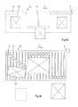
Fig. 1 is a plan view of an embodiment of the apparatus according to the invention. -
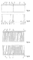
Fig. 2a is an enlarged view of a part ofFig. 1 indicated by II, andFig. 2b is a similar view asFig. 2a , but showing the bottom side of a transport container. -
Fig. 3a and 3b are similar views asFig. 2a and 2b , respectively, but showing an alternative embodiment of the transport container. -
Fig. 4a and 4b are similar views asFig. 2a and 2b , respectively, but showing another alternative embodiment of the transport container. -
Fig. 5 is an enlarged plan view of a part of the embodiment ofFig. 1 of which the transport containers are removed for clarity reasons. -
Fig. 6a and 6b are similar views asFig. 3a and 4a on a different scale, respectively, and illustrating the apparatus under operating conditions. -
Fig. 7a is a plan view of the embodiment ofFig. 3a on a different scale andFig. 7b is a bottom view of the corresponding part of the apparatus, illustrating the apparatus under operating conditions. -
Fig. 8a and 8b are similar views asFig. 7a and 7b , respectively, showing an alternative embodiment. -
Fig. 1 shows an embodiment of the apparatus 1 according to the invention as seen from above. The embodiment comprises a plurality oftransport containers 2 for supporting and transporting products. In this case the apparatus is arranged such that products can be placed on a supporting surface of thetransport containers 2 at one or more loading stations (not shown). Furthermore, the apparatus 1 is provided with one or more discharging stations (not shown) at which products can be discharged. Thetransport containers 2 are coupled to each other and driven synchronously in a transporting direction X by driving means, for example a chain. In practice, thetransport containers 2 may be coupled to each other indirectly, for example each of thetransport containers 2 may be individually coupled to the driving means. - The products are transported from the loading station to the discharging station. The
transport containers 2 are pivotable with respect to each other by means ofpivot members 3 such that a track that they follow may comprise bends in a horizontal plane.Fig. 1 shows an endless track comprising two bends and two straight portions in a horizontal plane. It is also possible that thepivot members 3 are adapted such that thetransport containers 2 are pivotable with respect to each other in a vertical plane such that a three-dimensional track can be followed. - The apparatus 1 is adapted to discharge products in a controlled way. The embodiment of the
transport container 2 as shown inFig. 2 comprises a discharging mechanism in the form of a pushingmember 4 which is moveable transversely with respect to the transporting direction X. This allows to push a product from thetransport container 2 at the desired discharging station to an exit (not shown). - The
transport container 2 ofFig. 2 comprises two pushingmembers 4. The pushingmembers 4 are located behind each other as seen in the transporting direction X. When thetransport container 2 supports one relatively short product as seen in the transporting direction X, located next to one of the pushing members, it is possible to activate only one pushingmember 4. In case of a relatively long product both pushingmembers 4 can be activated, possibly synchronously. In case of more than one relatively small product disposed on onetransport container 2 the pushingmembers 4 can be activated independently from each other. It is also possible that two or more products supported by onetransport container 2 are discharged at different discharging stations. -
Fig. 2b shows the bottom side of thetransport container 2 ofFig. 2a . The pushingmember 4 is coupled via a transmission to an actuator in the form of anactuator wheel 5. Under operating conditions, when thetransport container 2 moves in the transporting direction X theactuator wheel 5 may touch aguide actuator 6 such that theactuator wheel 5 must follow a guide 7. This is illustrated inFig. 5 . The guide 7 extends oblique with respect to the transporting direction X and may be fixed to aframe 8 of the apparatus 1. As shown inFig. 5 theguide actuator 6 can have an activated position (see the position of theleft guide actuator 6 inFig. 5 ) and a de-activated position (see the position of theright guide actuator 6 inFig. 5 ). In the de-activated position thetransport container 2 including the pushingmembers 4 passes theguide actuator 6 without being activated, which means that a product is not pushed from thetransport container 2. In the activated position theactuator wheel 5 is guided along theguide actuator 6 and the guide 7 thereby moving the corresponding pushingmember 4 transversely with respect to the transporting direction X. At an end portion of the guide 7 there is a space between the guide 7 and theframe 8 through which theactuator wheel 5 can move when thetransport container 2 passes. As a consequence, theactuator wheel 5 looses contact with the guide 7 and can be moved back to its original position. - As shown in
Fig. 2b theactuator wheel 5 is rotatably mounted to awheel support 9 which is movable within aslot 10, on the one hand, and connected to the pushingmember 4, on the other hand. Moving theactuator wheel 5 transversely with respect to the transporting direction leads to moving the pushingmember 4 in transverse direction, as well. - An alternative embodiment of a
transport container 2 is shown inFig. 3 . In this case thetransport container 2 comprises three pushingmembers 4. The pushingmember 4 disposed in the middle of thetransport container 2 is connected to thewheel support 9 through aslot 11 which extends perpendicularly to the transporting direction X. - Another alternative embodiment of a
transport container 2 is shown inFig. 4 . In this case thetransport container 2 comprises a plurality of pushingmembers 4. The supporting surface of thetransport container 2 is provided with a plurality ofslots 11 extending transversely with respect to the transporting direction X, through which slots 11 a mechanism for coupling the pushingmembers 4 to theactuator wheels 5 is present and within which the mechanism is movable. Theslots 11 may also serve to guide the pushingmembers 4 with respect to the supporting surface of thetransport container 2. -
Fig. 6a and 6b show the embodiments of thetransport containers 2 ofFig. 3 and 4 , respectively, under operating conditions at a discharging station.Products 12 are placed on the supporting surface of thetransport container 2 and pushed from thetransport container 2 in transverse direction of its transporting direction X. The embodiment ofFig. 6b shows that the pushingmembers 4 can be activated in such a way that the orientation of aproduct 12 with respect to thetransport container 2 can be influenced before theproduct 12 leaves thetransport container 2 by means of activating pushingmembers 4 located close to each other non-synchronously. If a series of adjacent pushingmembers 4 are activated synchronously the distance betweenadjacent guide actuators 6 and betweenadjacent actuator wheels 5 should be similar. -
Fig. 7a shows atransport container 2 having three pushingmembers 4. There are twoproducts 12 on the supporting surface of the transport container: along product 12 and ashort product 12 as seen in the transporting direction X.Fig. 7a illustrates that thelong product 12 is pushed from thetransport container 2 by displacing two corresponding and adjacent pushingmembers 4 synchronously. This is achieved by selecting the distance between twoactuator wheels 5 the same as the distance between two guides 7, as seen in the transporting direction X. This can be seen inFig. 7b. Fig. 7a and 7b also show a condition wherein theshort product 12 is not discharged at this discharging station because thecorresponding guide actuator 6 is not activated. -
Fig. 8a and 8b illustrate an alternative embodiment of the apparatus 1 which provides the possibility to pushproducts 12 from thetransport container 2 in opposite transverse directions with respect to the transporting direction X. For this reason the guides 7 are cross shaped. In this case the discharging stations may have exits at both sides of the track which is followed by thetransport containers 2. The advantage of this embodiment is thatproducts 12 on onetransport container 2 can be discharged at both sides of the track. - The
transport containers 2 may comprise wheels (not shown) which are supported by and run on theframe 8 of the apparatus 1. - From the foregoing it will be clear that the apparatus according to the invention is very flexible for transporting and sorting products of varying sizes at a relatively high speed.
- The invention is not limited to the embodiments shown in the drawings and described hereinbefore, which may be varied in different manners within the scope of the claims and their technical equivalents. For example, the pushing members may be activated in a different way with respect to the way through actuator wheels and guides as described hereinbefore.
Claims (4)
- An apparatus (1) for transport and controlled discharge of products (12), comprising at least a transport container (2) for supporting a product (12), a loading station for receiving a product (12) by the transport container (2), a discharging station for discharging a product (12) from the transport container (2) and driving means for transporting the transport container (2) in a transporting direction (X) from the loading station to the discharging station, wherein the transport container (2) comprises a pushing member (4) for pushing a product (12) from the transport container (2) when this is at the discharging station, which pushing member (4) is displaceable transversely with respect to the transporting direction (X), characterized in that the transport container (2) comprises at least another pushing member (4) for pushing a product (12) from the transport container (2) at the discharging station, wherein at least both pushing members (4) are located behind each other as seen in the transporting direction (X).
- An apparatus (1) according to claim 1, wherein the apparatus (1) comprises a series of said transport containers (2), which are transportable by the driving means.
- An apparatus (1) according to claim 1 or 2, wherein the pushing member (4) comprises an actuator (5) which is guidable along a guide (7) extending obliquely with respect to the transporting direction (X).
- An apparatus according to claim 3, wherein at least two actuators (5) of a transport container (2) are located at substantially the same distance with respect to each other as two corresponding guides (7), as seen in the transporting direction (X).
Applications Claiming Priority (1)
| Application Number | Priority Date | Filing Date | Title |
|---|---|---|---|
| NL2001922A NL2001922C (en) | 2008-08-26 | 2008-08-26 | An apparatus for transport and controlled discharge of products. |
Publications (2)
| Publication Number | Publication Date |
|---|---|
| EP2159174A1 true EP2159174A1 (en) | 2010-03-03 |
| EP2159174B1 EP2159174B1 (en) | 2012-06-20 |
Family
ID=40266079
Family Applications (1)
| Application Number | Title | Priority Date | Filing Date |
|---|---|---|---|
| EP09168562A Revoked EP2159174B1 (en) | 2008-08-26 | 2009-08-25 | An apparatus for transport and controlled discharge of products |
Country Status (3)
| Country | Link |
|---|---|
| EP (1) | EP2159174B1 (en) |
| ES (1) | ES2389330T3 (en) |
| NL (1) | NL2001922C (en) |
Cited By (5)
| Publication number | Priority date | Publication date | Assignee | Title |
|---|---|---|---|---|
| EP2682343A1 (en) * | 2011-04-29 | 2014-01-08 | TriNovate B.V. | An apparatus for transport and controlled discharge of products |
| WO2016056911A3 (en) * | 2014-10-09 | 2016-06-02 | Optimus Sorter Holding B.V. | Trays conveyor with pusher arms discharging objects |
| US9573773B2 (en) | 2014-09-18 | 2017-02-21 | Sdi Group Germany Material Handling Solutions Gmbh | Conveyor for transporting objects |
| WO2021195679A1 (en) | 2020-03-31 | 2021-10-07 | Knapp Ag | Method for sorting articles, and sorting device |
| DE102020131835A1 (en) | 2020-12-01 | 2022-06-02 | Rasch Consulting GmbH | Sorting installation and method for sorting objects |
Citations (6)
| Publication number | Priority date | Publication date | Assignee | Title |
|---|---|---|---|---|
| DE2941576A1 (en) * | 1979-10-13 | 1981-04-23 | Vetter Joachim | Glass bottle sorting device - selectively deflects pushers aligned with detected bottle to expel latter from conveying path |
| CA1127109A (en) * | 1980-02-11 | 1982-07-06 | Canadian Stackpole Limited | Bottle shifing apparatus |
| EP1020380A1 (en) * | 1999-01-11 | 2000-07-19 | Ebm Techniek B.V. | Separating device |
| DE19959843A1 (en) * | 1999-12-10 | 2001-06-13 | Sigma Innovationsgmbh | Piece goods conveyor has transporting carriage with flat carrying surface and means of unloading including pusher movable at right angles to direction of movement of carriage and sweeping over carrying surface |
| EP1123884A1 (en) * | 2000-02-10 | 2001-08-16 | Michael Dipl.-Ing. Horst | Device for diverting articles, in particular containers, from a path of travel |
| US20030221935A1 (en) * | 1998-12-01 | 2003-12-04 | Crisplant A/S | Conveyor/sorter system, a loading conveyor and a control system for such conveyors |
-
2008
- 2008-08-26 NL NL2001922A patent/NL2001922C/en active Search and Examination
-
2009
- 2009-08-25 ES ES09168562T patent/ES2389330T3/en active Active
- 2009-08-25 EP EP09168562A patent/EP2159174B1/en not_active Revoked
Patent Citations (6)
| Publication number | Priority date | Publication date | Assignee | Title |
|---|---|---|---|---|
| DE2941576A1 (en) * | 1979-10-13 | 1981-04-23 | Vetter Joachim | Glass bottle sorting device - selectively deflects pushers aligned with detected bottle to expel latter from conveying path |
| CA1127109A (en) * | 1980-02-11 | 1982-07-06 | Canadian Stackpole Limited | Bottle shifing apparatus |
| US20030221935A1 (en) * | 1998-12-01 | 2003-12-04 | Crisplant A/S | Conveyor/sorter system, a loading conveyor and a control system for such conveyors |
| EP1020380A1 (en) * | 1999-01-11 | 2000-07-19 | Ebm Techniek B.V. | Separating device |
| DE19959843A1 (en) * | 1999-12-10 | 2001-06-13 | Sigma Innovationsgmbh | Piece goods conveyor has transporting carriage with flat carrying surface and means of unloading including pusher movable at right angles to direction of movement of carriage and sweeping over carrying surface |
| EP1123884A1 (en) * | 2000-02-10 | 2001-08-16 | Michael Dipl.-Ing. Horst | Device for diverting articles, in particular containers, from a path of travel |
Cited By (8)
| Publication number | Priority date | Publication date | Assignee | Title |
|---|---|---|---|---|
| EP2682343A1 (en) * | 2011-04-29 | 2014-01-08 | TriNovate B.V. | An apparatus for transport and controlled discharge of products |
| US9242806B2 (en) | 2011-04-29 | 2016-01-26 | Trinovate B.V. | Apparatus for transport and controlled discharge of products |
| US9573773B2 (en) | 2014-09-18 | 2017-02-21 | Sdi Group Germany Material Handling Solutions Gmbh | Conveyor for transporting objects |
| WO2016056911A3 (en) * | 2014-10-09 | 2016-06-02 | Optimus Sorter Holding B.V. | Trays conveyor with pusher arms discharging objects |
| WO2021195679A1 (en) | 2020-03-31 | 2021-10-07 | Knapp Ag | Method for sorting articles, and sorting device |
| US11772131B2 (en) | 2020-03-31 | 2023-10-03 | Knapp Ag | Method for sorting articles, and sorting device |
| DE102020131835A1 (en) | 2020-12-01 | 2022-06-02 | Rasch Consulting GmbH | Sorting installation and method for sorting objects |
| EP4008443A1 (en) | 2020-12-01 | 2022-06-08 | Rasch Consulting GmbH | Sorting system and method for sorting objects |
Also Published As
| Publication number | Publication date |
|---|---|
| EP2159174B1 (en) | 2012-06-20 |
| ES2389330T3 (en) | 2012-10-25 |
| NL2001922C (en) | 2010-03-11 |
Similar Documents
| Publication | Publication Date | Title |
|---|---|---|
| EP2305582B1 (en) | Sorting device, in particular for pieces of luggage | |
| EP1972579B1 (en) | Transport system | |
| EP0626325B1 (en) | A conveyor | |
| EP2159174B1 (en) | An apparatus for transport and controlled discharge of products | |
| EP2238057B1 (en) | Sorting device in particular for pieces of luggage | |
| US20240425300A1 (en) | Cross-belt sorter | |
| US20100307107A1 (en) | Device for inserting products into packaging containers | |
| EP2682343B1 (en) | An apparatus for transport and controlled discharge of products | |
| CN102099271A (en) | Conveying mechanism with pushing-off device that can be driven counter to the direction of travel | |
| JP2016514657A (en) | Device for discharging a flat object being transported | |
| EP2197770B1 (en) | Sorting apparatus | |
| CN115959421A (en) | Transport device | |
| KR20140009992A (en) | Apparatus and method for forming groups of articles on a conveyor | |
| EP2616340B1 (en) | A device and a method for packaging substantially flat products in a box | |
| EP3798161B1 (en) | An apparatus for transport and controlled discharge of products | |
| JP2008265986A (en) | Article sorter | |
| EP0531801B1 (en) | Apparatus for automatically stacking differently sized panels or packs of panels | |
| EP3595994B1 (en) | Apparatus, system and method for sorting products | |
| JP4945085B2 (en) | Container alignment apparatus and container alignment method | |
| JPH08282830A (en) | Sorting device | |
| JP2006246748A5 (en) |
Legal Events
| Date | Code | Title | Description |
|---|---|---|---|
| PUAI | Public reference made under article 153(3) epc to a published international application that has entered the european phase |
Free format text: ORIGINAL CODE: 0009012 |
|
| AK | Designated contracting states |
Kind code of ref document: A1 Designated state(s): AT BE BG CH CY CZ DE DK EE ES FI FR GB GR HR HU IE IS IT LI LT LU LV MC MK MT NL NO PL PT RO SE SI SK SM TR |
|
| AX | Request for extension of the european patent |
Extension state: AL BA RS |
|
| 17P | Request for examination filed |
Effective date: 20100902 |
|
| GRAP | Despatch of communication of intention to grant a patent |
Free format text: ORIGINAL CODE: EPIDOSNIGR1 |
|
| GRAS | Grant fee paid |
Free format text: ORIGINAL CODE: EPIDOSNIGR3 |
|
| GRAA | (expected) grant |
Free format text: ORIGINAL CODE: 0009210 |
|
| AK | Designated contracting states |
Kind code of ref document: B1 Designated state(s): AT BE BG CH CY CZ DE DK EE ES FI FR GB GR HR HU IE IS IT LI LT LU LV MC MK MT NL NO PL PT RO SE SI SK SM TR |
|
| AX | Request for extension of the european patent |
Extension state: AL BA RS |
|
| REG | Reference to a national code |
Ref country code: GB Ref legal event code: FG4D |
|
| REG | Reference to a national code |
Ref country code: CH Ref legal event code: EP |
|
| REG | Reference to a national code |
Ref country code: AT Ref legal event code: REF Ref document number: 562964 Country of ref document: AT Kind code of ref document: T Effective date: 20120715 |
|
| REG | Reference to a national code |
Ref country code: IE Ref legal event code: FG4D |
|
| REG | Reference to a national code |
Ref country code: DE Ref legal event code: R096 Ref document number: 602009007649 Country of ref document: DE Effective date: 20120816 |
|
| REG | Reference to a national code |
Ref country code: NL Ref legal event code: T3 |
|
| REG | Reference to a national code |
Ref country code: ES Ref legal event code: FG2A Ref document number: 2389330 Country of ref document: ES Kind code of ref document: T3 Effective date: 20121025 |
|
| PG25 | Lapsed in a contracting state [announced via postgrant information from national office to epo] |
Ref country code: LT Free format text: LAPSE BECAUSE OF FAILURE TO SUBMIT A TRANSLATION OF THE DESCRIPTION OR TO PAY THE FEE WITHIN THE PRESCRIBED TIME-LIMIT Effective date: 20120620 Ref country code: FI Free format text: LAPSE BECAUSE OF FAILURE TO SUBMIT A TRANSLATION OF THE DESCRIPTION OR TO PAY THE FEE WITHIN THE PRESCRIBED TIME-LIMIT Effective date: 20120620 Ref country code: SE Free format text: LAPSE BECAUSE OF FAILURE TO SUBMIT A TRANSLATION OF THE DESCRIPTION OR TO PAY THE FEE WITHIN THE PRESCRIBED TIME-LIMIT Effective date: 20120620 Ref country code: NO Free format text: LAPSE BECAUSE OF FAILURE TO SUBMIT A TRANSLATION OF THE DESCRIPTION OR TO PAY THE FEE WITHIN THE PRESCRIBED TIME-LIMIT Effective date: 20120920 |
|
| REG | Reference to a national code |
Ref country code: LT Ref legal event code: MG4D Effective date: 20120620 |
|
| PG25 | Lapsed in a contracting state [announced via postgrant information from national office to epo] |
Ref country code: HR Free format text: LAPSE BECAUSE OF FAILURE TO SUBMIT A TRANSLATION OF THE DESCRIPTION OR TO PAY THE FEE WITHIN THE PRESCRIBED TIME-LIMIT Effective date: 20120620 Ref country code: LV Free format text: LAPSE BECAUSE OF FAILURE TO SUBMIT A TRANSLATION OF THE DESCRIPTION OR TO PAY THE FEE WITHIN THE PRESCRIBED TIME-LIMIT Effective date: 20120620 Ref country code: GR Free format text: LAPSE BECAUSE OF FAILURE TO SUBMIT A TRANSLATION OF THE DESCRIPTION OR TO PAY THE FEE WITHIN THE PRESCRIBED TIME-LIMIT Effective date: 20120921 Ref country code: SI Free format text: LAPSE BECAUSE OF FAILURE TO SUBMIT A TRANSLATION OF THE DESCRIPTION OR TO PAY THE FEE WITHIN THE PRESCRIBED TIME-LIMIT Effective date: 20120620 |
|
| PG25 | Lapsed in a contracting state [announced via postgrant information from national office to epo] |
Ref country code: EE Free format text: LAPSE BECAUSE OF FAILURE TO SUBMIT A TRANSLATION OF THE DESCRIPTION OR TO PAY THE FEE WITHIN THE PRESCRIBED TIME-LIMIT Effective date: 20120620 Ref country code: SK Free format text: LAPSE BECAUSE OF FAILURE TO SUBMIT A TRANSLATION OF THE DESCRIPTION OR TO PAY THE FEE WITHIN THE PRESCRIBED TIME-LIMIT Effective date: 20120620 Ref country code: RO Free format text: LAPSE BECAUSE OF FAILURE TO SUBMIT A TRANSLATION OF THE DESCRIPTION OR TO PAY THE FEE WITHIN THE PRESCRIBED TIME-LIMIT Effective date: 20120620 Ref country code: BE Free format text: LAPSE BECAUSE OF FAILURE TO SUBMIT A TRANSLATION OF THE DESCRIPTION OR TO PAY THE FEE WITHIN THE PRESCRIBED TIME-LIMIT Effective date: 20120620 Ref country code: IS Free format text: LAPSE BECAUSE OF FAILURE TO SUBMIT A TRANSLATION OF THE DESCRIPTION OR TO PAY THE FEE WITHIN THE PRESCRIBED TIME-LIMIT Effective date: 20121020 Ref country code: CY Free format text: LAPSE BECAUSE OF FAILURE TO SUBMIT A TRANSLATION OF THE DESCRIPTION OR TO PAY THE FEE WITHIN THE PRESCRIBED TIME-LIMIT Effective date: 20120620 Ref country code: CZ Free format text: LAPSE BECAUSE OF FAILURE TO SUBMIT A TRANSLATION OF THE DESCRIPTION OR TO PAY THE FEE WITHIN THE PRESCRIBED TIME-LIMIT Effective date: 20120620 |
|
| PG25 | Lapsed in a contracting state [announced via postgrant information from national office to epo] |
Ref country code: PL Free format text: LAPSE BECAUSE OF FAILURE TO SUBMIT A TRANSLATION OF THE DESCRIPTION OR TO PAY THE FEE WITHIN THE PRESCRIBED TIME-LIMIT Effective date: 20120620 Ref country code: PT Free format text: LAPSE BECAUSE OF FAILURE TO SUBMIT A TRANSLATION OF THE DESCRIPTION OR TO PAY THE FEE WITHIN THE PRESCRIBED TIME-LIMIT Effective date: 20121022 |
|
| PLBI | Opposition filed |
Free format text: ORIGINAL CODE: 0009260 |
|
| PG25 | Lapsed in a contracting state [announced via postgrant information from national office to epo] |
Ref country code: MC Free format text: LAPSE BECAUSE OF NON-PAYMENT OF DUE FEES Effective date: 20120831 |
|
| PLAX | Notice of opposition and request to file observation + time limit sent |
Free format text: ORIGINAL CODE: EPIDOSNOBS2 |
|
| 26 | Opposition filed |
Opponent name: OPTIMUS SORTER HOLDING B.V. Effective date: 20130319 |
|
| PG25 | Lapsed in a contracting state [announced via postgrant information from national office to epo] |
Ref country code: DK Free format text: LAPSE BECAUSE OF FAILURE TO SUBMIT A TRANSLATION OF THE DESCRIPTION OR TO PAY THE FEE WITHIN THE PRESCRIBED TIME-LIMIT Effective date: 20120620 |
|
| REG | Reference to a national code |
Ref country code: IE Ref legal event code: MM4A |
|
| REG | Reference to a national code |
Ref country code: DE Ref legal event code: R026 Ref document number: 602009007649 Country of ref document: DE Effective date: 20130319 |
|
| PG25 | Lapsed in a contracting state [announced via postgrant information from national office to epo] |
Ref country code: BG Free format text: LAPSE BECAUSE OF FAILURE TO SUBMIT A TRANSLATION OF THE DESCRIPTION OR TO PAY THE FEE WITHIN THE PRESCRIBED TIME-LIMIT Effective date: 20120920 Ref country code: IE Free format text: LAPSE BECAUSE OF NON-PAYMENT OF DUE FEES Effective date: 20120825 |
|
| PLAF | Information modified related to communication of a notice of opposition and request to file observations + time limit |
Free format text: ORIGINAL CODE: EPIDOSCOBS2 |
|
| PLBB | Reply of patent proprietor to notice(s) of opposition received |
Free format text: ORIGINAL CODE: EPIDOSNOBS3 |
|
| PG25 | Lapsed in a contracting state [announced via postgrant information from national office to epo] |
Ref country code: MT Free format text: LAPSE BECAUSE OF FAILURE TO SUBMIT A TRANSLATION OF THE DESCRIPTION OR TO PAY THE FEE WITHIN THE PRESCRIBED TIME-LIMIT Effective date: 20120620 |
|
| REG | Reference to a national code |
Ref country code: CH Ref legal event code: PL |
|
| PG25 | Lapsed in a contracting state [announced via postgrant information from national office to epo] |
Ref country code: LI Free format text: LAPSE BECAUSE OF NON-PAYMENT OF DUE FEES Effective date: 20130831 Ref country code: TR Free format text: LAPSE BECAUSE OF FAILURE TO SUBMIT A TRANSLATION OF THE DESCRIPTION OR TO PAY THE FEE WITHIN THE PRESCRIBED TIME-LIMIT Effective date: 20120620 Ref country code: CH Free format text: LAPSE BECAUSE OF NON-PAYMENT OF DUE FEES Effective date: 20130831 |
|
| PG25 | Lapsed in a contracting state [announced via postgrant information from national office to epo] |
Ref country code: SM Free format text: LAPSE BECAUSE OF FAILURE TO SUBMIT A TRANSLATION OF THE DESCRIPTION OR TO PAY THE FEE WITHIN THE PRESCRIBED TIME-LIMIT Effective date: 20120620 Ref country code: LU Free format text: LAPSE BECAUSE OF NON-PAYMENT OF DUE FEES Effective date: 20120825 |
|
| PG25 | Lapsed in a contracting state [announced via postgrant information from national office to epo] |
Ref country code: HU Free format text: LAPSE BECAUSE OF FAILURE TO SUBMIT A TRANSLATION OF THE DESCRIPTION OR TO PAY THE FEE WITHIN THE PRESCRIBED TIME-LIMIT Effective date: 20090825 |
|
| PLBI | Opposition filed |
Free format text: ORIGINAL CODE: 0009260 |
|
| 26 | Opposition filed |
Opponent name: SDI GROUP MATERIAL HANDLING SOLUTIONS GMBH Effective date: 20150427 |
|
| RDAF | Communication despatched that patent is revoked |
Free format text: ORIGINAL CODE: EPIDOSNREV1 |
|
| PG25 | Lapsed in a contracting state [announced via postgrant information from national office to epo] |
Ref country code: MK Free format text: LAPSE BECAUSE OF FAILURE TO SUBMIT A TRANSLATION OF THE DESCRIPTION OR TO PAY THE FEE WITHIN THE PRESCRIBED TIME-LIMIT Effective date: 20120620 |
|
| REG | Reference to a national code |
Ref country code: FR Ref legal event code: PLFP Year of fee payment: 7 |
|
| APAH | Appeal reference modified |
Free format text: ORIGINAL CODE: EPIDOSCREFNO |
|
| APBM | Appeal reference recorded |
Free format text: ORIGINAL CODE: EPIDOSNREFNO |
|
| APBP | Date of receipt of notice of appeal recorded |
Free format text: ORIGINAL CODE: EPIDOSNNOA2O |
|
| PLAB | Opposition data, opponent's data or that of the opponent's representative modified |
Free format text: ORIGINAL CODE: 0009299OPPO |
|
| APBQ | Date of receipt of statement of grounds of appeal recorded |
Free format text: ORIGINAL CODE: EPIDOSNNOA3O |
|
| R26 | Opposition filed (corrected) |
Opponent name: OPTIMUS SORTER HOLDING B.V. Effective date: 20130319 |
|
| REG | Reference to a national code |
Ref country code: FR Ref legal event code: PLFP Year of fee payment: 8 |
|
| REG | Reference to a national code |
Ref country code: FR Ref legal event code: PLFP Year of fee payment: 9 |
|
| PGFP | Annual fee paid to national office [announced via postgrant information from national office to epo] |
Ref country code: NL Payment date: 20170830 Year of fee payment: 9 |
|
| PGFP | Annual fee paid to national office [announced via postgrant information from national office to epo] |
Ref country code: ES Payment date: 20170901 Year of fee payment: 9 Ref country code: DE Payment date: 20170829 Year of fee payment: 9 Ref country code: FR Payment date: 20170825 Year of fee payment: 9 Ref country code: GB Payment date: 20170829 Year of fee payment: 9 Ref country code: IT Payment date: 20170823 Year of fee payment: 9 |
|
| REG | Reference to a national code |
Ref country code: DE Ref legal event code: R064 Ref document number: 602009007649 Country of ref document: DE Ref country code: DE Ref legal event code: R103 Ref document number: 602009007649 Country of ref document: DE |
|
| APBU | Appeal procedure closed |
Free format text: ORIGINAL CODE: EPIDOSNNOA9O |
|
| PGFP | Annual fee paid to national office [announced via postgrant information from national office to epo] |
Ref country code: AT Payment date: 20170802 Year of fee payment: 9 |
|
| RDAG | Patent revoked |
Free format text: ORIGINAL CODE: 0009271 |
|
| STAA | Information on the status of an ep patent application or granted ep patent |
Free format text: STATUS: PATENT REVOKED |
|
| 27W | Patent revoked |
Effective date: 20171113 |
|
| GBPR | Gb: patent revoked under art. 102 of the ep convention designating the uk as contracting state |
Effective date: 20171113 |
|
| REG | Reference to a national code |
Ref country code: AT Ref legal event code: MA03 Ref document number: 562964 Country of ref document: AT Kind code of ref document: T Effective date: 20171113 |