EP2158984A1 - Mold for continuous casting of round billet cast piece and method of continuous casting thereof - Google Patents
Mold for continuous casting of round billet cast piece and method of continuous casting thereof Download PDFInfo
- Publication number
- EP2158984A1 EP2158984A1 EP07791280A EP07791280A EP2158984A1 EP 2158984 A1 EP2158984 A1 EP 2158984A1 EP 07791280 A EP07791280 A EP 07791280A EP 07791280 A EP07791280 A EP 07791280A EP 2158984 A1 EP2158984 A1 EP 2158984A1
- Authority
- EP
- European Patent Office
- Prior art keywords
- mold
- region
- change
- rate
- inner diameter
- Prior art date
- Legal status (The legal status is an assumption and is not a legal conclusion. Google has not performed a legal analysis and makes no representation as to the accuracy of the status listed.)
- Withdrawn
Links
Images



Classifications
-
- B—PERFORMING OPERATIONS; TRANSPORTING
- B22—CASTING; POWDER METALLURGY
- B22D—CASTING OF METALS; CASTING OF OTHER SUBSTANCES BY THE SAME PROCESSES OR DEVICES
- B22D11/00—Continuous casting of metals, i.e. casting in indefinite lengths
- B22D11/04—Continuous casting of metals, i.e. casting in indefinite lengths into open-ended moulds
- B22D11/043—Curved moulds
-
- B—PERFORMING OPERATIONS; TRANSPORTING
- B22—CASTING; POWDER METALLURGY
- B22D—CASTING OF METALS; CASTING OF OTHER SUBSTANCES BY THE SAME PROCESSES OR DEVICES
- B22D11/00—Continuous casting of metals, i.e. casting in indefinite lengths
- B22D11/10—Supplying or treating molten metal
- B22D11/108—Feeding additives, powders, or the like
Definitions
- the present invention relates to a continuous casting mold used in continuously casting round billets with a curved type continuous casting apparatus and a continuous casting method of round billets in which said continuous casting mold is used.
- the billet In continuously casting a round billet having a round shape cross section, compared with the continuous casting of a rectangular billet having a rectangular shape cross section, the billet is unevenly cooled because a mold inner wall (an inner peripheral surface in the case of the round billet mold) is unstably in contact with the billet.
- a mold inner wall an inner peripheral surface in the case of the round billet mold
- Japanese Utility Model Application Publication No. 59(1984)-165748 proposes a mold, in which an inner diameter is decreased downward and a decrease ratio of the inner diameter is changed in two steps.
- Japanese Utility Model Application Publication No. 59(1984)-165749 proposes a mold, in which a tapered surface whose inner diameter is continuously decreased downward and the change in inner diameter is matched with the solidification shrinking. According to the proposed molds, it is said that the uniform contact can be achieved between the mold inner peripheral surface and the billet.
- the applicant has proposed a mold in Japanese Patent No. 3022211 , in which the uniform contact is achieved between the mold inner peripheral surface and the billet to perform uniform cooling in continuously casting the round billet.
- the mold from the upper edge to the lower edge is divided into at least three regions along the casting direction, and the inner diameter of the mold is gradually decreased from the upper edge toward the lower edge by defining a rate of change in mold inner diameter per unit length along the casting direction in each region.
- an object of the present invention is to provide a continuous casting mold which can stably perform the continuous casting of the casting-defect-free round billet and a continuous casting method in which the continuous casting mold is used when the round billet is continuously cast with the curved type continuous casting apparatus.
- the mold is divided into three regions along the casting direction, the rate of change Tp in mold inner diameter ranges from 12 to 16 %/m in a first region, the first region being allocated from an upper edge of a cooled mold surface to a zone of 50-100 mm, the cooled mold surface being the side which molten steel is poured to, the zone of 50-100mm being between the positions of 50 mm and 100 mm away from the upper mold edge, the rate of change Tp in mold inner diameter continuously varies from 12-16 %/m to 0.8-1.4 %/m in a second region, the second region successively following the first region and being allocated from said zone of 50-100mm to a zone of 250-300 mm, the zone of 250-300mm being between the positions of 250 mm and 300 mm away from the upper mold edge, and the rate of change Tp in mold inner diameter ranges from 0.8 to 1.4 %/m in a third region, the third region successively following the second region and
- the rate of change Rp in curvature radius ranges from 6 ⁇ (D 0 /R 0 ) to 8 ⁇ (D 0 /R 0 ) (%/m) in a first region, the first region being from the upper edge of the cooled mold surface to the zone of 50-100mm, the cooled mold surface being the side to which molten steel is poured, the zone of 50-100mm being between the positions of 50mm and 100 mm away from the upper mold edge, the rate of change Rp in curvature radius continuously varies from 6 ⁇ (D 0 /R 0 )-8 ⁇ (D 0 /R 0 ) (%/m) to 0.4 ⁇ (D 0 /R 0 )-0.7 ⁇ (D 0 /R 0 ) (%/m) in a second region, the second region successively following the first region and being allocated from said zone of 50-100mm to a zone of 250-300 mm, the zone of 250-300mm
- a round billet continuous casting method in which the round billet continuous casting mold is used, the round billet continuous casting method is characterized in that continuous casting is performed while a mold powder is being fed onto a surface of the molten steel poured into the continuous casting mold, wherein the mold powder having a viscosity of 0.1 to 1.0 Pa ⁇ s at 1573K, a solidification temperature of not less than 1273K, and a mass % ratio of 1.0 to 1.4 in terms of ((CaO+CaF 2 ⁇ 0.718)/SiO 2 ), a Na content of not more than 5.0 mass% in Na 2 O equivalent, a F concentration of not more than 7.0 mass%, a Mg content of 5-13 mass% in MgO equivalent, and an Al content of 6-18 mass% in Al 2 O 3 equivalent.
- the uniform and good contact between the billet and the mold inner peripheral surface is achieved over the whole circumference because the force is evenly exerted to the whole circumference of the billet.
- the casting-defect-free high-quality round billet can stably be produced.
- Fig. 1 is a vertical cross section showing a frame format of configuration of a conventional round billet continuous casting mold.
- a conventional mold 101 used in the curved type continuous casting apparatus has a constant length-wise curvature radius Ro of a datum line 101c along the outer length-wise curvature side in the inner peripheral surface.
- the curvature radius Ro is substantially matched with the curvature radius of the outer curvature side of a billet 11 withdrawn from the mold 101.
- a mold inner diameter Do at its lower edge 101b is determined according to each diameter of the billet 11.
- the inner diameter of the mold 101 is shrunk from an upper edge 101a toward the lower edge 101b, namely, the inner peripheral surface is tapered in a length-wise direction such that the inner diameter is enlarged from the lower edge 101b toward the upper edge 101a.
- the outer curvature side is restricted by the constant curvature radius Ro, the enlargement of the inner diameter is born by the inner curvature side.
- a center line MC representing a plot of centers of the mold 101 inside diameters at elevations ranging from the lower edge 101b to the upper edge 101a, deviates from a center line BC which represents a center line of the billet to the inner curvature side toward the upper edge 101a of the mold 101, although matching with the center line BC at the lower edge 101b.
- Fig. 2 is a vertical cross section showing a frame format of configuration of a round billet continuous casting mold according to the present invention.
- Do is the inner diameter at a lower edge 1b of the mold 1
- Ro is the curvature radius of a datum line 1c along the outer curvature side in the inner peripheral surface at the lower edge 1b of the mold 1.
- the mold inner diameter Do at the lower edge 1b of the mold is determined according to each diameter of the billet 11 to be cast.
- the curvature radius Ro at the lower edge 1b of the mold 1 is substantially matched with the curvature radius of the outer curvature side of the billet 11 withdrawn from the mold 1, which is inherently owned by the applied curved type continuous casting apparatus.
- the inner peripheral surface of the mold 1 has a length-wise tapered shape such that the inner diameter thereof is gradually increased from the lower edge 1b toward the upper edge 1a.
- D is a mold inner diameter at a distance x from the upper edge 1a of the cooled mold surface
- the rate of change Tp in mold inner diameter can be expressed by Formula 1.
- R is a curvature radius of the datum line 1c along the outer curvature side
- the rate of change Rp in curvature radius at this position can be expressed by Formula 2.
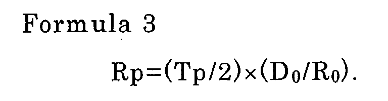
- the mold inner diameter D and the curvature radius R are set at the distance x away from the upper edge 1a of the cooled mold surface such that at this position, the rate of change Tp in mold inner diameter and the rate of change Rp in curvature radius satisfy Formula 3.
- the inner diameter D and the curvature radius R are set according to the definition of Formula 3, the inner diameter is gradually increased from the lower edge 1b toward the upper edge 1a in the inner peripheral surface of the mold 1 while the increase in inner diameter is evenly distributed to the outer curvature side and the inner curvature side. That is, a center line MC representing a plot of inside diameter centers at elevations ranging from the lower edge 1b and the upper edge 1a is matched with a center line BC of the round billet 11 over the whole region from the lower edge 1b to the upper edge 1a of the mold 1.
- Formula 3 can be derived from the relationship between Formula 4 and 5. Therefore, when the relationship expressed by Formula 3 is satisfied, the center line MC of the mold inner peripheral surface is matched with the center line BC of the billet 11.
- the continuous casting mold of the present invention in performing the continuous casting of the round billet with the mold, because the center line of the mold inner peripheral surface is matched with the center line of the billet, the mold does not exert the biased force to the billet, and the even force is exerted to the whole circumference of the billet. Therefore, the uniform and good contact between the billet and the mold inner peripheral surface is achieved over the whole circumference, which allows the high-quality round billet to be stably obtained. The same holds true for the case in which the steel having the different solidification shrinking amount is cast or the case in which the casting speed is changed during the casting.
- the continuous casting mold is divided into three regions along the casting direction, the rate of change Tp in mold inner diameter ranges from 12 to 16 %/m in a first region, the first region being allocated from an upper edge of a cooled mold surface to a zone of 50-100 mm, the mold surface being the side which molten steel is poured to, the zone of 50-100mm being between the positions of 50mm and 100mm away from the upper mold edge, the rate of change Tp in mold inner diameter of continuously varies from 12-16 %/m to 0.8-1.4 %/m in a second region, the second region successively following the first region and being allocated from said zone of 50-100mm to a zone of 250-300 mm, the zone of 250-300mm being between the positions of 250 mm and 300mm away from the upper mold edge, and the rate of change Tp in mold inner diameter ranges from 0.8 to 1.4 %/m in a third region, the third region successively following the second region and being from said zone of 250-300mm to the lower
- the rate of change Rp in curvature radius ranges from 6 ⁇ (D 0 /R 0 ) to 8 ⁇ (D 0 /R 0 ) (%/m) in a first region, the first region being allocated from an upper edge of a cooled mold surface to a zone of 50-100mm, the mold surface is the side which molten steel is poured to, the zone of 50-100mm being between the positions of 50mm and 100mm away from the upper mold edge, the rate of change Rp in curvature radius continuously varies from 6 ⁇ (D 0 /R 0 )-8 ⁇ (D 0 /R 0 ) (%/m) to 0.4 ⁇ (D 0 /R 0 )-0:7 ⁇ (D 0 /R 0 ) (%/m) in a second region, the second region successively following the first region and being from said zone of 50-100mm to a zone of 250-300 mm, the zone of 250-300mm being between the positions of 250mm and
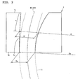
- Fig. 3 is a vertical cross section for explaining a specific example of the round billet continuous casting mold of the invention.
- the tapered inner peripheral surface of the mold is constant and the curved state is not shown in Fig. 3 .
- the mold 1 of the present invention to the lower edge 1b from the upper edge 1a of a cooled mold surface side where molten steel 10 is poured is divided into three regions A1, A2, and A3 along the casting direction.
- a boundary between the first region Al and the second region A2 is located within a zone ranging from 50 to 100 mm from the upper edge 1a of the cooled mold surface side, and a boundary between the second region A2 and the third region A3 is located within a zone ranging from 250 to 300 mm from the upper edge 1a of the cooled mold surface.
- the rate of change Tp in mold inner diameter is set to 12 to 16 %/m in the first region A1
- the rate of change Tp in mold inner diameter is continuously varied from 12-16 %/m to 0.8-1.4 %/m in the second region A2 which successively follows the first region A1
- the rate of change Tp in mold inner diameter of the mold is set to 0.8-1.4 %/m in the third region A3 which successively follows the second region A2.
- the reason why the rate of change Tp in mold inner diameter is set to the range of 12 to 16 %/m in the first region that is allocated from the upper mold edge to the zone of 50-100mm is that the first region is used to effectively achieve the uniform contact between the mold inner peripheral surface and the billet. That is, when the first region is shorter than 50 mm, the shrinking of the mold becomes smaller than the shrinking of the solidified shell, which causes the non-uniform contact to generate longitudinal cracking. On the other hand, when the first region is longer than 100 mm, the shrinking of the mold becomes excessively large to generate constraint due to the seizure between the mold and billet. The constraint is generated when the rate of change Tp in mold inner diameter is excessively larger than a specified value, and the longitudinal cracking is generated when the rate of change Tp in mold inner diameter of the mold is excessively smaller than the specified value.
- the seizure-related constraint is generated when the rate of change Tp in mold inner diameter is excessively larger than the specified value, and the longitudinal cracking is generated when the rate of change Tp in mold inner diameter is excessively smaller than the specified value. Further, in the third region between the end of the second region and the lower mold edge, it is for the same reason that the rate of change Tp in mold inner diameter is set to the range of 0.8 to 1.4 %/m.
- the use of the continuous casting mold of the specific example can achieve the better contact between the billet and the mold inner peripheral surface to obtain the high-quality round billet.
- the mold powder which constitutes a heat transfer medium between the mold inner peripheral surface and the billet a material having the following physical properties and composition is used in the mold of the present invention, which allows the higher-quality round billet to be obtained compared with the use of the conventional mold powder.
- the mold powder having the following physical properties and composition can be used in the round billet continuous casting mold of the invention. That is, a viscosity of 0.1 to 1.0 Pa ⁇ s at 1573K, a solidification temperature of not less than 1273K, and a mass % ratio of 1.0 to 1.4 in terms of ((CaO+CaF 2 ⁇ 0.718)/SiO 2 ), a Na content of not more than 5.0 mass% in Na 2 O equivalent, a F concentration of not more than 7.0 mass%, a Mg content of 5 to 13 mass% in MgO equivalent, and an Al content of 6 to 18 mass% in Al 2 O 3 equivalent.
- Table 1 shows the physical properties and composition of the mold powder.
- the powder when the viscosity at 1573K is lower than 0.1 (Pa ⁇ S), the powder is non-uniformly poured between the mold inner peripheral surface and the billet, and the heat is non-uniformly dissipated. This causes the generation of the longitudinal cracking or seizure-related constraint and/or the defect by migrating the powder into molten steel.
- the viscosity when the viscosity is more than 1.0 Pa.s, the lack of the inflow of the powder between the mold inner peripheral surface and the billet causes the generation of the seizure-related constraint.
- the composition of the crystal is changed during the casting to non-uniformly provide the cooling.
- the Al content in Al 2 O 3 equivalent is more than 18 mass%, the powder is hardly flowed inbetween the billet and the mold inner peripheral surface because the solidification temperature is associated to become excessively high.
- the round billet having the better quality can be produced, when the continuous casting is performed while the mold powder having the physical properties and composition defined as described above is fed onto the surface of the molten steel in the mold of the present invention.
- Tests were performed with a curved type continuous casting apparatus which has an one-point straightening device in order to confirm the effects of the mold of the present invention and the continuous casting method in which the mold was used.
- the curved type continuous casting apparatus which has an one-point straightening device had the curvature radius (R 0 ) of 10m.
- the steels having C ranging from 0.06 to 0.35 mass% and Mn ranging from 0.8 to 1.8 mass% were used in the test of the embodiment. Although it is not always necessary to contain Cr, Cr is set to less than 3 mass% when Cr is contained.
- the casting tests were performed with three steel grades A, B, and C shown in Table 2.
- the molten steel was poured into molds M1 to M20 (having the inner diameter(Do) of 225 mm at the lower edge of the mold and the length of 900 mm) shown in Table 3, mold powder P1 to P11 shown in Table 4 was fed onto the surface of the molten steel, and the continuous casting was performed at a casting speed of 2.0 m/min.
- Table 5 shows casting conditions A to AF which are in combination of the steel grades A to C, the molds M1 to M20, and the powder P1 to P11 in the embodiment.
- test result was evaluated by a variation range in mold copper surface temperature representing how is the contact between the mold inner peripheral surface and the billet, an index of the longitudinal cracking, and the presence or absence of a withdrawal-disabled accident.
- Fig. 4 is a diagram showing a variation range of a mold copper surface temperature for each casting condition in the embodiment.
- the mold temperature variation range of Fig. 4 shows an effective value (numeric integration average) of the temperature variation of a thermocouple disposed 150 mm away from the upper edge of the mold surface.
- the thermocouple was disposed inside by 15 mm from the copper surface.
- Fig. 5 is a diagram showing an index of longitudinal cracking for each casting condition in the embodiment.
- the index of longitudinal cracking in Fig. 5 is a cracking length per unit length of the billet.
- the mold copper surface temperature exhibited a large variation which is of an issue in the commercial operation, and the large longitudinal cracking was generated.
- the powder P4, P5, P6, and P7 which were of the comparative example were used in the casting conditions W, X, Y, and Z, and the improper mold powder generated the large variation in copper surface temperature.
- the casting conditions R, S, and T in which the molds M18, M19, and M20 as being the comparative example were used and although the rate of change in mold inner diameter was within the proper range, the rate of change in the curvature radius of the casting apparatus was out of the proper range. Therefore, the uniform contact was not maintained between the billet and the mold inner peripheral surface.
- the round billet continuous casting mold of the present invention in continuously casting the round billet with the curved type continuous casting apparatus, the even force is exerted to the whole circumference of the billet, and the uniform and good contact between the billet and the mold inner peripheral surface is achieved over the whole circumference, so that the casting-defect-free high-quality round billet can stably be produced. Accordingly, the present invention is extremely useful in the continuous casting mold and the continuous casting method in which the high-quality round billet can be produced with the curved type continuous casting apparatus.
Landscapes
- Engineering & Computer Science (AREA)
- Mechanical Engineering (AREA)
- Continuous Casting (AREA)
Abstract


where D in Formula 1 is a mold inner diameter at a distance x away from an upper mold edge and R in Formula 2 is a curvature radius of the outer curvature side at the distance x,
Description
- The present invention relates to a continuous casting mold used in continuously casting round billets with a curved type continuous casting apparatus and a continuous casting method of round billets in which said continuous casting mold is used.
- In continuously casting a round billet having a round shape cross section, compared with the continuous casting of a rectangular billet having a rectangular shape cross section, the billet is unevenly cooled because a mold inner wall (an inner peripheral surface in the case of the round billet mold) is unstably in contact with the billet. When the billet is excessively unevenly cooled, a longitudinal cracking defect is generated in the billet, and a break out is generated due to the longitudinal cracking defect. Therefore, the casting cannot be continued at last.
- In order to circumvent the generation of such situation, there have been proposed such various methods that an inner diameter of the mold is decreased according to solidification shrinking, and mold powder fed into the mold are improved during the continuous casting to adjust contact between the mold inner peripheral surface and the billet. For example, Japanese Utility Model Application Publication No.
59(1984)-165748 59(1984)-165749 - However, in the mold proposed in Japanese Utility Model Application Publication No.
59(1984)-165748 59(1984)-165749 - The applicant has proposed a mold in Japanese Patent No.
3022211 - However, in the mold proposed in Japanese Patent No.
3022211 - In view of the foregoing, an object of the present invention is to provide a continuous casting mold which can stably perform the continuous casting of the casting-defect-free round billet and a continuous casting method in which the continuous casting mold is used when the round billet is continuously cast with the curved type continuous casting apparatus.
- In order to achieve the object, the present invention provides a mold for continuously casting a round billet with a curved type continuous casting apparatus, the mold having an inner diameter Do (m) at a lower edge thereof, and an outer length-wise curvature (hereinafter, "curvature" is generally used to designate "length-wise curvature") surface having a curvature radius Ro (m) at the lower edge of the mold, and at the same time the round billet continuous casting mold characterized in that, when a rate of change Tp (%/m) in mold inner diameter per unit length along a casting direction is expressed by Formula 1, and when a rate of change Rp (%/m) in curvature radius of an outer curvature side per unit length along the casting direction is expressed by
Formula 2, the rate of change Tp in mold inner diameter and the rate of change Rp in curvature radius satisfy a relationship expressed by Formula 3;
where D is a mold inner diameter at a distance x away from an upper edge of a cooled mold surface,
where R is a curvature radius of an outer curvature-side at a distance x away from an upper edge of a cooled mold surface, and
- In the configuration of the present invention, because a center line of the inner peripheral surface of the mold is aligned with a center line of the billet in continuously casting the round billet, a biased force is not exerted to the billet from the mold and an even force is exerted over the whole circumference, and the uniform and good contact between the billet and the mold inner peripheral surface can be obtained over the whole circumference.
- In the round billet continuous casting mold according to the present invention, preferably the mold is divided into three regions along the casting direction, the rate of change Tp in mold inner diameter ranges from 12 to 16 %/m in a first region, the first region being allocated from an upper edge of a cooled mold surface to a zone of 50-100 mm, the cooled mold surface being the side which molten steel is poured to, the zone of 50-100mm being between the positions of 50 mm and 100 mm away from the upper mold edge, the rate of change Tp in mold inner diameter continuously varies from 12-16 %/m to 0.8-1.4 %/m in a second region, the second region successively following the first region and being allocated from said zone of 50-100mm to a zone of 250-300 mm, the zone of 250-300mm being between the positions of 250 mm and 300 mm away from the upper mold edge, and the rate of change Tp in mold inner diameter ranges from 0.8 to 1.4 %/m in a third region, the third region successively following the second region and being allocated from said zone of 250-300mm to the lower edge of the mold.
- In the round billet continuous casting mold according to the present invention, the rate of change Rp in curvature radius ranges from 6×(D0/R0) to 8×(D0/R0) (%/m) in a first region, the first region being from the upper edge of the cooled mold surface to the zone of 50-100mm, the cooled mold surface being the side to which molten steel is poured, the zone of 50-100mm being between the positions of 50mm and 100 mm away from the upper mold edge, the rate of change Rp in curvature radius continuously varies from 6×(D0/R0)-8×(D0/R0) (%/m) to 0.4×(D0/R0)-0.7×(D0/R0) (%/m) in a second region, the second region successively following the first region and being allocated from said zone of 50-100mm to a zone of 250-300 mm, the zone of 250-300mm being between the positions of 250mm and 300mm away from the upper mold edge, and the rate of change Rp in curvature radius ranges from 0.4×(D0/R0) to 0.7×(D0/R0) (%/m) in a third region, the third region successively following the second region and being from said zone of 250-300mm to the lower mold edge, preferably.
- Further, in order to achieve the above-mentioned object, a round billet continuous casting method in which the round billet continuous casting mold is used, the round billet continuous casting method is characterized in that continuous casting is performed while a mold powder is being fed onto a surface of the molten steel poured into the continuous casting mold, wherein the mold powder having a viscosity of 0.1 to 1.0 Pa·s at 1573K, a solidification temperature of not less than 1273K, and a mass % ratio of 1.0 to 1.4 in terms of ((CaO+CaF2×0.718)/SiO2), a Na content of not more than 5.0 mass% in Na2O equivalent, a F concentration of not more than 7.0 mass%, a Mg content of 5-13 mass% in MgO equivalent, and an Al content of 6-18 mass% in Al2O3 equivalent.
- According to the round billet continuous casting mold of the invention and the continuous casting method of the present invention in which the mold is used, in the continuous casting with the curved type continuous casting apparatus, the uniform and good contact between the billet and the mold inner peripheral surface is achieved over the whole circumference because the force is evenly exerted to the whole circumference of the billet. As a result, the casting-defect-free high-quality round billet can stably be produced.
-
-
Fig. 1 is a vertical cross section showing a frame format of configuration of a conventional round billet continuous casting mold; -
Fig. 2 is a vertical cross section showing a frame format of configuration of a round billet continuous casting mold according to the present invention; -
Fig. 3 is a vertical cross section for explaining a specific example of the round billet continuous casting mold of the invention; -
Fig. 4 is a diagram showing a variation range of a mold copper surface temperature for each casting condition in embodiment; and -
Fig. 5 is a diagram showing an index of longitudinal cracking for each casting condition in the embodiment. - The inventors studied in detail the problems involved in the conventional mold used in the curved type continuous casting apparatus, and the inventors completed the invention by paying attention to the curvature radius of the mold which the attention has not been given to because of a design standard.
-
Fig. 1 is a vertical cross section showing a frame format of configuration of a conventional round billet continuous casting mold. As shown inFig. 1 , aconventional mold 101 used in the curved type continuous casting apparatus has a constant length-wise curvature radius Ro of adatum line 101c along the outer length-wise curvature side in the inner peripheral surface. The curvature radius Ro is substantially matched with the curvature radius of the outer curvature side of abillet 11 withdrawn from themold 101. A mold inner diameter Do at itslower edge 101b is determined according to each diameter of thebillet 11. - As with the molds proposed in Japanese Utility Model Application Publication No.
59(1984)-165748 59(1984)-165749 3022211 mold 101, the inner diameter of themold 101 is shrunk from an upper edge 101a toward thelower edge 101b, namely, the inner peripheral surface is tapered in a length-wise direction such that the inner diameter is enlarged from thelower edge 101b toward the upper edge 101a. At this point, in the inner peripheral surface of themold 101, because the outer curvature side is restricted by the constant curvature radius Ro, the enlargement of the inner diameter is born by the inner curvature side. Therefore, a center line MC, representing a plot of centers of themold 101 inside diameters at elevations ranging from thelower edge 101b to the upper edge 101a, deviates from a center line BC which represents a center line of the billet to the inner curvature side toward the upper edge 101a of themold 101, although matching with the center line BC at thelower edge 101b. - When the
round billet 11 is continuously cast with themold 101, a bias force is always exerted to thebillet 11 from the inner curvature side toward the outer curvature side. Therefore, in theconventional mold 101, the billet comes into uneven contact with the inner peripheral surface of themold 101 in the whole circumference, which results in a problem that thebillet 11 is deformed. For example, in the case where the steel having a different solidification shrinking amount is cast, or in the case where a casting speed is changed during casting, the problem is very likely caused because the bias force exerted to the billet is changed. - In order to solve the problem, in the continuous casting mold of the present invention, not only the rate of change in mold inner diameter is defined, but also the rate of change in curvature radius of mold and the relationship between the rates of changes are defined.
- That is, a mold according to the present invention is used to continuously cast a round billet with a curved type continuous casting apparatus, assuming that Do (m) is a mold inner diameter at a lower edge of the mold and Ro (m) is a curvature radius of an outer curvature side at the lower edge of the mold, when a rate of change Tp (%/m) in mold inner diameter per unit length along a casting direction is expressed by Formula 1, and when a rate of change Rp (%/m) in curvature radius of an outer curvature side per unit length along the casting direction is expressed by
Formula 2, the rate of change Tp in mold inner diameter and the rate of change Rp in curvature radius satisfy a relationship expressed by Formula 3;
where D is a mold inner diameter at a distance x away from an upper edge of a cooled mold surface,
where R is a curvature radius of an outer curvature side at a distance x away from an upper edge of a cooled mold surface, and
-
Fig. 2 is a vertical cross section showing a frame format of configuration of a round billet continuous casting mold according to the present invention. As shown inFig. 2 , in amold 1 according to the invention used in the curved type continuous casting apparatus, it is assumed that Do is the inner diameter at alower edge 1b of themold 1 and Ro is the curvature radius of adatum line 1c along the outer curvature side in the inner peripheral surface at thelower edge 1b of themold 1. The mold inner diameter Do at thelower edge 1b of the mold is determined according to each diameter of thebillet 11 to be cast. The curvature radius Ro at thelower edge 1b of themold 1 is substantially matched with the curvature radius of the outer curvature side of thebillet 11 withdrawn from themold 1, which is inherently owned by the applied curved type continuous casting apparatus. - The inner peripheral surface of the
mold 1 has a length-wise tapered shape such that the inner diameter thereof is gradually increased from thelower edge 1b toward theupper edge 1a. At this point, assuming that D is a mold inner diameter at a distance x from theupper edge 1a of the cooled mold surface, the rate of change Tp in mold inner diameter can be expressed by Formula 1. Similarly, assuming that at a distance x from theupper edge 1a of the cooled mold surface, R is a curvature radius of thedatum line 1c along the outer curvature side, the rate of change Rp in curvature radius at this position can be expressed byFormula 2. And, the mold inner diameter D and the curvature radius R are set at the distance x away from theupper edge 1a of the cooled mold surface such that at this position, the rate of change Tp in mold inner diameter and the rate of change Rp in curvature radius satisfy Formula 3. - When the mold inner diameter D and the curvature radius R are set according to the definition of Formula 3, the inner diameter is gradually increased from the
lower edge 1b toward theupper edge 1a in the inner peripheral surface of themold 1 while the increase in inner diameter is evenly distributed to the outer curvature side and the inner curvature side. That is, a center line MC representing a plot of inside diameter centers at elevations ranging from thelower edge 1b and theupper edge 1a is matched with a center line BC of theround billet 11 over the whole region from thelower edge 1b to theupper edge 1a of themold 1. - The reason why such situation is defined by Formula 3 is as follows. In order to match the center line MC of the mold inner peripheral surface with the center line BC of the billet, it is necessary that the increase in inner diameter of the
mold 1 be evenly distributed to the outer curvature side and the inner curvature side while centering around the center line BC of thebillet 11. Therefore, it is necessary that a half (1/2) of the rate of change Tp in mold inner diameter is assigned to the curvature radius R of the outer curvature side at the distance x away from theupper edge 1a of the mold surface. This enables the curvature radius R of the outer curvature side to be expressed by a following Formula 4 based on the rate of change Tp in mold inner diameter:
- Similarly, the curvature radius R of the outer curvature side can be expressed by a following Formula 5 based on the rate of change Rp in curvature radius:

- Formula 3 can be derived from the relationship between Formula 4 and 5. Therefore, when the relationship expressed by Formula 3 is satisfied, the center line MC of the mold inner peripheral surface is matched with the center line BC of the
billet 11. - According to the continuous casting mold of the present invention, in performing the continuous casting of the round billet with the mold, because the center line of the mold inner peripheral surface is matched with the center line of the billet, the mold does not exert the biased force to the billet, and the even force is exerted to the whole circumference of the billet. Therefore, the uniform and good contact between the billet and the mold inner peripheral surface is achieved over the whole circumference, which allows the high-quality round billet to be stably obtained. The same holds true for the case in which the steel having the different solidification shrinking amount is cast or the case in which the casting speed is changed during the casting.
- Then, a preferred example of the continuous casting mold of the present invention will be described in the followings.
- In the specific example, the continuous casting mold is divided into three regions along the casting direction, the rate of change Tp in mold inner diameter ranges from 12 to 16 %/m in a first region, the first region being allocated from an upper edge of a cooled mold surface to a zone of 50-100 mm, the mold surface being the side which molten steel is poured to, the zone of 50-100mm being between the positions of 50mm and 100mm away from the upper mold edge, the rate of change Tp in mold inner diameter of continuously varies from 12-16 %/m to 0.8-1.4 %/m in a second region, the second region successively following the first region and being allocated from said zone of 50-100mm to a zone of 250-300 mm, the zone of 250-300mm being between the positions of 250 mm and 300mm away from the upper mold edge, and the rate of change Tp in mold inner diameter ranges from 0.8 to 1.4 %/m in a third region, the third region successively following the second region and being from said zone of 250-300mm to the lower edge of the mold. At this point, the rate of change Rp in curvature radius is determined so as to satisfy the relationship of Formula 3 based on the rate of change Tp in mold inner diameter.
- In other words, the rate of change Rp in curvature radius ranges from 6×(D0/R0) to 8×(D0/R0) (%/m) in a first region, the first region being allocated from an upper edge of a cooled mold surface to a zone of 50-100mm, the mold surface is the side which molten steel is poured to, the zone of 50-100mm being between the positions of 50mm and 100mm away from the upper mold edge, the rate of change Rp in curvature radius continuously varies from 6×(D0/R0)-8×(D0/R0) (%/m) to 0.4×(D0/R0)-0:7×(D0/R0) (%/m) in a second region, the second region successively following the first region and being from said zone of 50-100mm to a zone of 250-300 mm, the zone of 250-300mm being between the positions of 250mm and 300mm away from the upper mold edge, and the rate of change Rp in curvature radius ranges from 0.4×(D0/R0) to 0.7×(D0/R0) (%/m) in a third region, the third region successively following the second region and being from said zone of 250-300mm to the lower edge of the mold. At this point, the rate of change Tp in mold inner diameter is determined so as to satisfy the relationship of Formula 3 based on the rate of change Rp in curvature radius.
-
Fig. 3 is a vertical cross section for explaining a specific example of the round billet continuous casting mold of the invention. For convenience, the tapered inner peripheral surface of the mold is constant and the curved state is not shown inFig. 3 . - As shown in
Fig. 3 , themold 1 of the present invention to thelower edge 1b from theupper edge 1a of a cooled mold surface side wheremolten steel 10 is poured is divided into three regions A1, A2, and A3 along the casting direction. A boundary between the first region Al and the second region A2 is located within a zone ranging from 50 to 100 mm from theupper edge 1a of the cooled mold surface side, and a boundary between the second region A2 and the third region A3 is located within a zone ranging from 250 to 300 mm from theupper edge 1a of the cooled mold surface. The rate of change Tp in mold inner diameter is set to 12 to 16 %/m in the first region A1, the rate of change Tp in mold inner diameter is continuously varied from 12-16 %/m to 0.8-1.4 %/m in the second region A2 which successively follows the first region A1, and the rate of change Tp in mold inner diameter of the mold is set to 0.8-1.4 %/m in the third region A3 which successively follows the second region A2. During the continuous casting, mold powders 12 are fed onto the surface of themolten steel 10 in themold 1. - The reason why the rate of change Tp in mold inner diameter is set to the range of 12 to 16 %/m in the first region that is allocated from the upper mold edge to the zone of 50-100mm is that the first region is used to effectively achieve the uniform contact between the mold inner peripheral surface and the billet. That is, when the first region is shorter than 50 mm, the shrinking of the mold becomes smaller than the shrinking of the solidified shell, which causes the non-uniform contact to generate longitudinal cracking. On the other hand, when the first region is longer than 100 mm, the shrinking of the mold becomes excessively large to generate constraint due to the seizure between the mold and billet. The constraint is generated when the rate of change Tp in mold inner diameter is excessively larger than a specified value, and the longitudinal cracking is generated when the rate of change Tp in mold inner diameter of the mold is excessively smaller than the specified value.
- The reason why the rate of change Tp in mold inner diameter is continuously varied from 12-16 %/m to 0.8-1.4 %/m in the second region that is allocated next to the first region and from said zone of 50-100mm to the zone of 250-300mm, is that when the second region is shorter than the range determined by the datum point of 250 mm, the shrinking of the mold becomes smaller than the shrinking of the solidified shell, which causes the non-uniform contact to generate longitudinal cracking. On the other hand, when the second region is longer than the range determined by the datum point of 300 mm, the shrinking of the mold becomes excessively large to generate constraint due to the seizure between the mold and the billet. The seizure-related constraint is generated when the rate of change Tp in mold inner diameter is excessively larger than the specified value, and the longitudinal cracking is generated when the rate of change Tp in mold inner diameter is excessively smaller than the specified value. Further, in the third region between the end of the second region and the lower mold edge, it is for the same reason that the rate of change Tp in mold inner diameter is set to the range of 0.8 to 1.4 %/m.
- The use of the continuous casting mold of the specific example can achieve the better contact between the billet and the mold inner peripheral surface to obtain the high-quality round billet. As for the mold powder which constitutes a heat transfer medium between the mold inner peripheral surface and the billet, a material having the following physical properties and composition is used in the mold of the present invention, which allows the higher-quality round billet to be obtained compared with the use of the conventional mold powder.
- The mold powder having the following physical properties and composition can be used in the round billet continuous casting mold of the invention. That is, a viscosity of 0.1 to 1.0 Pa·s at 1573K, a solidification temperature of not less than 1273K, and a mass % ratio of 1.0 to 1.4 in terms of ((CaO+CaF2×0.718)/SiO2), a Na content of not more than 5.0 mass% in Na2O equivalent, a F concentration of not more than 7.0 mass%, a Mg content of 5 to 13 mass% in MgO equivalent, and an Al content of 6 to 18 mass% in Al2O3 equivalent. Table 1 shows the physical properties and composition of the mold powder.
-
Table 1 Viscosity at 1573K 0.1 to 1.0 Pa·s Solidification temperature 1273K or more Mass % ratio in terms of ((CaO+CaF2x 0.718)/SiO2) 1.0 to 1.4 Na content in Na2O equivalent 5.0 mass% or less F concentration 7.0 mass% or less Mg content in MgO equivalent 5 to 13 mass% Al content in Al2O3 equivalent 6 to 18 mass% (Note) *Solidification temperature expresses a temperature at which viscosity rises rapidly in viscosity measurement.
*Because usually a cationic concentration is determined in a chemical analysis value, the content is defined by converting the chemical analysis value into a concentration in oxide equivalent.
*For CaO, the value is expressed by converting a Ca concentration into a Cao concentration. - In the mold powder, when the viscosity at 1573K is lower than 0.1 (Pa·S), the powder is non-uniformly poured between the mold inner peripheral surface and the billet, and the heat is non-uniformly dissipated. This causes the generation of the longitudinal cracking or seizure-related constraint and/or the defect by migrating the powder into molten steel. On the other hand, when the viscosity is more than 1.0 Pa.s, the lack of the inflow of the powder between the mold inner peripheral surface and the billet causes the generation of the seizure-related constraint.
- When the solidification temperature is lower than 1273K, a liquid phase of the powder is increased between the mold inner peripheral surface and the billet, and the cooling is excessively provided. Therefore, the billet is distorted by a thermal stress to generate the longitudinal cracking.
- When the mass % ratio in terms of ((CaO+CaF2×0.718)/SiO2) is lower than 1.0, SiO2 in the powder oxidizes Mn in the molten steel to change the composition, and the defect is generated in the billet surface. And when the Mg content in MgO equivalent is lower than 5 mass%, because crystallization is not stabilized, the cooling is excessively provided to generate the longitudinal cracking. On the other hand, when the mass % ratio in terms of ((CaO+CaF2×0.718)/SiO2) is more than 1.4, or when the Mg content in MgO equivalent is more than 13 mass%, the powder film is excessively shrunk, and the good contact is disturbed between the billet and the mold inner peripheral surface to generate the longitudinal cracking, or the powder is not melted because the solidification temperature is associated to become excessively high.
- When the Na content in Na2O equivalent is more than 5.0 mass%, or when F concentration is more than 7.0 mass%, a melting behavior of the powder becomes defective to generate an entrapment defect, etc.
- When the Al content in Al2O3 equivalent is less than 6 mass%, the composition of the crystal is changed during the casting to non-uniformly provide the cooling. On the other hand, when the Al content in Al2O3 equivalent is more than 18 mass%, the powder is hardly flowed inbetween the billet and the mold inner peripheral surface because the solidification temperature is associated to become excessively high.
- Accordingly, the round billet having the better quality can be produced, when the continuous casting is performed while the mold powder having the physical properties and composition defined as described above is fed onto the surface of the molten steel in the mold of the present invention.
- Tests were performed with a curved type continuous casting apparatus which has an one-point straightening device in order to confirm the effects of the mold of the present invention and the continuous casting method in which the mold was used. The curved type continuous casting apparatus which has an one-point straightening device had the curvature radius (R0) of 10m. The steels having C ranging from 0.06 to 0.35 mass% and Mn ranging from 0.8 to 1.8 mass% were used in the test of the embodiment. Although it is not always necessary to contain Cr, Cr is set to less than 3 mass% when Cr is contained. The casting tests were performed with three steel grades A, B, and C shown in Table 2.
-
Table 2 Steel grade Chemical composition (mass %) Balance: Fe and impurities C Mn Si P S Cr Al A 0.27 0.41 0.26 0.0080 0.0030 0.97 0.035 B 0.23 1.29 0.30 0.0110 0.0060 0.46 0.025 C 0.22 0.61 0.18 0.0220 0.0060 - 0.018 (Note) "-" shows that the element is not contained. - In the embodiment, the molten steel was poured into molds M1 to M20 (having the inner diameter(Do) of 225 mm at the lower edge of the mold and the length of 900 mm) shown in Table 3, mold powder P1 to P11 shown in Table 4 was fed onto the surface of the molten steel, and the continuous casting was performed at a casting speed of 2.0 m/min. Table 5 shows casting conditions A to AF which are in combination of the steel grades A to C, the molds M1 to M20, and the powder P1 to P11 in the embodiment.
-
Table 3 M1 M2 M3 M4 M5 M6 M7 M8 M9 M10 First region Boundary of second region (mm) 40* 110* 75 75 75 75 75 75 50 100 Rate of change in mold inner diameter (%/m) 14.0 14.0 11.0* 17.0* 14.0 14.0 14.0 14.0 14.0 14.0 Rate of change in curvature radius (%/m) 0.158 0158 0.124 0.191 0.158 0.158 0.158 0.158 0.158 0.158 Second region Boundary of third region (mm) 275 275 275 275 240* 310* 275 275 275 275 Rate of change in mold inner diameter in first region (%/m) 14.0 14.0 11.0* 17.0* 14.0 14.0 14.0 14.0 14.0 14.0 Rate of change in mold inner diameter in third region (%/m) 1.1 1.1 1.1 1.1 1.1 1.1 0.7 1.5 1.1 1.1 Rate of change in curvature radius in first region (%/m) 0.158 0.158 0.124 0.191 0.158 0.158 0.158 0.158 0.158 0.158 Rate of change in curvature radius in third region (%/m) 0.012 0.012 0.012 0.012 0.012 0.012 0.008 0.017 0.012 0.012 Third region Rate of change in mold inner diameter (%/m) 1.1 1.1 1.1 1.1 1.1 1.1 0.7* 1.5* 1.1 1.1 Rate of change in curvature radius (%/m) 0.012 0.012 0.012 0.012 0.012 0.012 0.008 0.017 0.012 0.012 Classification C C C C C C C C I I M11 M12 M13 M14 M15 M16 M17 M18 M19 M20 First region Boundary of second region (mm) 75 75 75 75 75 75 75 75 75 75 Rate of change in mold inner diameter (%/m) 12.0 16.0 14.0 14.0 14.0 14.0 14.0 14.0 14.0 14.0 Rate of change in curvature radius (%/m) 0.135 0.180 0.158 0.158 0.158 0.158 0.158 0* 0* 0* Second region Boundary of third region (mm) 275 275 250 300 275 275 275 275 275 275 Rate of change in mold inner diameter in first region (%/m) 12.0 16.0 14.0 14.0 14.0 14..0 14.0 14.0 14.0 14.0 Rate of change in mold inner diameter in third region (%/m) 1.1 1.1 1.1 1.1 1.1 0.8 1.4 1.1 0.8 1.4 Rate of change in curvature radius in first region (%/m) 0.135 0.180 0.158 0.158 0.158 0.158 0.158 0* 0* 0* Rate of change in curvature radius in third region (%/m) 0.012 0.012 0.012 0.012 0.012 0.009 0.016 0* 0* 0* Third region Rate of change in mold inner diameter (%/m) 1.1 1.1 1.1 1.1 1.1 0.8 1.4 1.1 0.8 1.4 Rate of change in curvature radius (%/m) 0012 0.012 0.012 0.012 0.012 0.009 0.016 0* 0* 0* Classification I I I I I I I C C C (Note) In classification, "1" means Inventive example" and G" means comparative example.
"*" shows that the numerical data deviates from the range defined in the present invention. -
Table 4 P1 P2 P3 P4 P5 P6 P7 P8 P9 P10 P11 Viscosity (Pa·s) 0.50 0.40 0.60 040 0.60 0.35 0.36 0.49 0.52 0.48 0.53 Solidification temperature (K) 1505 1512 1495 1600 1460 1465 1463 1505 1520 1500 1520 Basicity (-) 1.20 1.40 1.00 1.45* 0.95* 1.20 1.20 1.20 1.20 1.20 1.20 Na2O (mass %) 0.5 0.5 0.5 0.5 0.5 6.0* 0.5 4.0 2.0 4..0 4.0 F (mass %) 4.0 4.0 4.0 4.0 4.0 4.0 8.0* 4.0 4.0 4.0 4.0 MgO (mass %) 8.0 8.0 8.0 8.0 8.0 8.0 8.0 6.0 13.0 8.0 8.0 Al2O3 (mass %) 11.0 11.0 11.0 11.0 11.0 11.0 11.0 11.0 11.0 7.0 18.0 Classification I I I C C C C I I I I (Note) Basicity means the mass ratio of (CaO+CaF2×0.718)/SiO2.
In classification, "I" means Inventive example and "C" means Comparative example.
"*" shows that the numerical data deviates from the range defined in the present invention. -
Table 5 Casting condition A B C D E F G H I J K Steel grade A A A A A A A A A A A Mold M1* M2* M3* M4* M5* M6* M7* M8* M9 M10 M11 Mold powder P1 P1 P1 P1 P1 P1 P1 P1 P1 P1 P1 Classification C C C C C C C C I I I Casting condition L M N O P Q R S T U V Steel grade A A A A A A A A A A A Mold M12 M13 M14 M15 M16 M17 M18* M19* M20* M15 M15 Mold powder P1 P1 P1 P1 P1 P1 P1 P1 P1 P2 P3 Classification I I I I I I C C C I I Casting condition W X Y Z AA AB AC AD AE AF Steel grade A A A A A A A A B C Mold M15 M15 M15 M15 M15 M15 M15 M15 M15 M15 Mold powder P4* P5* P6* P7* P8 P9 P10 P11 P1 P1 Classification C C C C I I I I I I (Note) In classification, "I" means Inventive example and "C" means Comparative example.
"*" shows that the numerical data deviates from the range defined in the present invention. - The test result was evaluated by a variation range in mold copper surface temperature representing how is the contact between the mold inner peripheral surface and the billet, an index of the longitudinal cracking, and the presence or absence of a withdrawal-disabled accident.
-
Fig. 4 is a diagram showing a variation range of a mold copper surface temperature for each casting condition in the embodiment. The mold temperature variation range ofFig. 4 shows an effective value (numeric integration average) of the temperature variation of a thermocouple disposed 150 mm away from the upper edge of the mold surface. The thermocouple was disposed inside by 15 mm from the copper surface. -
Fig. 5 is a diagram showing an index of longitudinal cracking for each casting condition in the embodiment. The index of longitudinal cracking inFig. 5 is a cracking length per unit length of the billet. - As is clear from
Figs. 4 and5 , for the casting conditions I to Q, U, V, and AA to AF of the inventive example, the variation in mold copper surface temperature fell well within a tolerable range causing no problem, and the longitudinal cracking was hardly generated. Additionally, a break out or an alarm of seizure-related constraint was not caused. - On the contrary, for the casting conditions A, C, E, F, R to T, and W to Z of the comparative example, the mold copper surface temperature exhibited a large variation which is of an issue in the commercial operation, and the large longitudinal cracking was generated. Among others, the powder P4, P5, P6, and P7 which were of the comparative example were used in the casting conditions W, X, Y, and Z, and the improper mold powder generated the large variation in copper surface temperature. For the casting conditions R, S, and T in which the molds M18, M19, and M20 as being the comparative example were used, and although the rate of change in mold inner diameter was within the proper range, the rate of change in the curvature radius of the casting apparatus was out of the proper range. Therefore, the uniform contact was not maintained between the billet and the mold inner peripheral surface.
- For the casting conditions B, D, G, and H as being the comparative example, although the copper surface temperature exhibits the small variation, the molds M1, M4, M7, and M8 as being the comparative example were used. Therefore, the withdrawal-disabled accident was occurred because the rate of change in mold inner diameter was out of the proper range.
- According to the round billet continuous casting mold of the present invention and the continuous casting method in which said mold is used, in continuously casting the round billet with the curved type continuous casting apparatus, the even force is exerted to the whole circumference of the billet, and the uniform and good contact between the billet and the mold inner peripheral surface is achieved over the whole circumference, so that the casting-defect-free high-quality round billet can stably be produced. Accordingly, the present invention is extremely useful in the continuous casting mold and the continuous casting method in which the high-quality round billet can be produced with the curved type continuous casting apparatus.
Claims (4)
- A mold for continuously casting a round billet with a curved type continuous casting apparatus, in which the mold has an inner diameter Do (m) at a lower edge thereof, and an outer curvature side thereof is configured to have a curvature radius Ro (m) at the lower edge thereof,
the mold being characterized in that:given that a rate of change Tp (%/m) in mold inner diameter per unit length along a casting direction is expressed by Formula 1, and a rate of change Rp (%/m) in curvature radius of an outer curvature side per unit length along the casting direction is expressed by Formula 2, the rate of change Tp in mold inner diameter and the rate of change Rp in curvature radius satisfy a relationship expressed by Formula 3;
where D is a mold inner diameter at a distance x away from an upper edge of a cooled mold surface,
where R is a curvature radius of an outer curvature side at a distance x away from an upper edge of a cooled mold surface, and
- The round billet continuous casting mold according to claim 1, characterized in that the mold is divided into three regions along a casting direction, the rate of change Tp in mold inner diameter ranges from 12 to 16 %/m in a first region, the first region being allocated from an upper edge of a cooled mold surface to a zone of 50-100mm, the cooled mold surface being the side which molten steel is poured to, the zone of 50-100mm being between the positions of 50mm and 100mm away from the upper mold edge, the rate of change Tp in mold inner diameter continuously varies from 12-16 %/m to 0.8-1.4 %/m in a second region, the second region successively following the first region and being allocated from said zone of 50-100mm to a zone of 250-300mm, the zone of 250-300mm being between the positions of 250mm and 300mm away from the upper mold edge, and the rate of change Tp in mold inner diameter ranges from 0.8 to 1.4 %/m in a third region, the third region successively following the second region and being allocated from said zone of 250-300mm to the lower mold edge.
- The round billet continuous casting mold according to claim 1, characterized in that the mold is divided into three regions along the casting direction, the rate of change Rp in curvature radius ranges from 6×(D0/R0) to 8×(D0/R0) (%/m) in a first region, the first region being allocated from an upper edge of a cooled mold surface to a zone of 50-100mm, the cooled mold surface being the side which molten steel is poured to, the zone of 50-100mm being between the positions of 50mm and 100mm away from the upper mold edge, the rate of change Rp in curvature radius continuously varies from 6×(D0/R0)-8×(D0/R0) (%/m) to 0.4×(D0/R0)-0.7×(D0/R0) (%/m) in a second region, the second region successively following the first region and being allocated from said zone of 50-100mm to a zone of 250-300mm, the zone of 250-300mm being between the positions of 250mm and 300mm away from the upper mold edge, and the rate of change Rp in curvature radius ranges from 0.4×(D0/R0) to 0.7×(D0/R0) (%/m) in a third region, the third region successively following the second region and being allocated from said zone of 250-300mm to the lower mold edge.
- A round billet continuous casting method in which the round billet continuous casting mold as in any one of claims 1 to 3 is used, characterized in that continuous casting is performed while a mold powder is being fed onto a surface of the molten steel poured into the continuous casting mold, the mold powder having a viscosity of 0.1 to 1.0 Pa·s at 1573K, a solidification temperature of not less than 1273K, and a mass % ratio of 1.0 to 1.4 in terms of ((CaO+CaF2×0.718)/SiO2), a Na content of not more than 5.0 mass% in Na2O equivalent, a F concentration of not more than 7.0 mass%, a Mg content of 5 to 13 mass% in MgO equivalent, and an Al content of 6 to 18 mass% in Al2O3 equivalent.
Applications Claiming Priority (2)
| Application Number | Priority Date | Filing Date | Title |
|---|---|---|---|
| JP2007170396A JP5018274B2 (en) | 2007-06-28 | 2007-06-28 | Mold for continuous casting of round billet slab and continuous casting method |
| PCT/JP2007/064564 WO2009001481A1 (en) | 2007-06-28 | 2007-07-25 | Mold for continuous casting of round billet cast piece and method of continuous casting thereof |
Publications (2)
| Publication Number | Publication Date |
|---|---|
| EP2158984A1 true EP2158984A1 (en) | 2010-03-03 |
| EP2158984A4 EP2158984A4 (en) | 2017-03-29 |
Family
ID=40185311
Family Applications (1)
| Application Number | Title | Priority Date | Filing Date |
|---|---|---|---|
| EP07791280.6A Withdrawn EP2158984A4 (en) | 2007-06-28 | 2007-07-25 | Mold for continuous casting of round billet cast piece and method of continuous casting thereof |
Country Status (10)
| Country | Link |
|---|---|
| US (2) | US8225843B2 (en) |
| EP (1) | EP2158984A4 (en) |
| JP (1) | JP5018274B2 (en) |
| CN (1) | CN101678442B (en) |
| AR (1) | AR063893A1 (en) |
| BR (1) | BRPI0721797B1 (en) |
| CA (1) | CA2683984C (en) |
| MX (1) | MX2009012872A (en) |
| RU (1) | RU2434707C2 (en) |
| WO (1) | WO2009001481A1 (en) |
Families Citing this family (6)
| Publication number | Priority date | Publication date | Assignee | Title |
|---|---|---|---|---|
| CN101844210B (en) * | 2010-04-27 | 2012-08-08 | 攀钢集团工程技术有限公司 | Continuous casting machine arc section supporting structure and mounting method thereof |
| JP5817681B2 (en) * | 2012-08-22 | 2015-11-18 | 新日鐵住金株式会社 | Mold for continuous casting of high alloy steel round billet slab and continuous casting method |
| JP6136782B2 (en) * | 2013-09-04 | 2017-05-31 | 新日鐵住金株式会社 | High Cr steel continuous casting method |
| JP6515394B2 (en) * | 2015-11-05 | 2019-05-22 | 日本製鉄株式会社 | Mold flux for continuous casting and continuous casting method |
| US10788934B2 (en) * | 2017-05-14 | 2020-09-29 | Microsoft Technology Licensing, Llc | Input adjustment |
| CN115446279A (en) * | 2022-09-06 | 2022-12-09 | 中南大学 | Corner temperature field thermal simulation device of round chamfer crystallizer and application |
Family Cites Families (15)
| Publication number | Priority date | Publication date | Assignee | Title |
|---|---|---|---|---|
| DE2923398C2 (en) * | 1979-06-06 | 1981-07-09 | Mannesmann AG, 4000 Düsseldorf | Device for measuring a curved continuous casting mold |
| CA1209770A (en) | 1982-12-17 | 1986-08-19 | Robert C. Heritage | Openwork screen assembly |
| JPS59165748A (en) | 1984-02-24 | 1984-09-19 | アイカ工業株式会社 | Top plate |
| JPS6432184A (en) | 1987-07-28 | 1989-02-02 | Yokogawa Electric Corp | Continuous core loss measuring instrument |
| JPH0628093B2 (en) | 1989-06-20 | 1994-04-13 | 科学技術庁金属材料技術研究所長 | Magnetic recording medium |
| RU2015175C1 (en) * | 1991-03-05 | 1994-06-30 | Виниченко Николай Иванович | Method of producing slag-forming mixture |
| RU2044597C1 (en) * | 1992-12-24 | 1995-09-27 | Владимир Ильич Лебедев | Crystallizer of curvilinear-type machine for continuous casting of metal |
| IT1265065B1 (en) * | 1993-05-17 | 1996-10-30 | Giovanni Arvedi | PERFECTED INGOT MILL FOR CONTINUOUS STEEL CASTING, PARTICULARLY SUITABLE FOR CONTINUOUS CASTING OF THIN Slabs |
| JP3008821B2 (en) * | 1994-07-29 | 2000-02-14 | 住友金属工業株式会社 | Continuous casting method and apparatus for thin slab |
| JP3022211B2 (en) | 1994-11-08 | 2000-03-15 | 住友金属工業株式会社 | Mold for continuous casting of round billet slab and continuous casting method using the mold |
| DE19742795A1 (en) * | 1997-09-27 | 1999-04-01 | Schloemann Siemag Ag | Funnel geometry of a mold for the continuous casting of metal |
| CN2386908Y (en) * | 1999-09-21 | 2000-07-12 | 许壮凌 | Crystallizer |
| CZ290001B6 (en) * | 2000-04-28 | 2002-05-15 | Třinecké Železárny A. S. | Circular crystallizer |
| JP3886774B2 (en) * | 2001-10-30 | 2007-02-28 | 三島光産株式会社 | Continuous casting mold considering slab casting radius change due to shrinkage and continuous casting equipment using the same |
| CN1528545A (en) * | 2003-09-26 | 2004-09-15 | 燕山大学 | Continuous caster roll profile with continuous bending section and two continuous straightening sections |
-
2007
- 2007-06-28 JP JP2007170396A patent/JP5018274B2/en active Active
- 2007-07-25 BR BRPI0721797A patent/BRPI0721797B1/en active IP Right Grant
- 2007-07-25 MX MX2009012872A patent/MX2009012872A/en active IP Right Grant
- 2007-07-25 CN CN2007800530491A patent/CN101678442B/en active Active
- 2007-07-25 RU RU2010102712/02A patent/RU2434707C2/en active
- 2007-07-25 CA CA2683984A patent/CA2683984C/en not_active Expired - Fee Related
- 2007-07-25 EP EP07791280.6A patent/EP2158984A4/en not_active Withdrawn
- 2007-07-25 WO PCT/JP2007/064564 patent/WO2009001481A1/en not_active Ceased
- 2007-11-21 AR ARP070105181A patent/AR063893A1/en active IP Right Grant
-
2009
- 2009-10-15 US US12/579,495 patent/US8225843B2/en active Active
-
2012
- 2012-06-21 US US13/529,262 patent/US8397792B2/en active Active
Also Published As
| Publication number | Publication date |
|---|---|
| CN101678442B (en) | 2012-06-27 |
| US20100032127A1 (en) | 2010-02-11 |
| CA2683984A1 (en) | 2008-12-31 |
| BRPI0721797B1 (en) | 2015-11-10 |
| US8397792B2 (en) | 2013-03-19 |
| WO2009001481A1 (en) | 2008-12-31 |
| JP5018274B2 (en) | 2012-09-05 |
| AR063893A1 (en) | 2009-02-25 |
| RU2010102712A (en) | 2011-08-10 |
| EP2158984A4 (en) | 2017-03-29 |
| US8225843B2 (en) | 2012-07-24 |
| RU2434707C2 (en) | 2011-11-27 |
| CA2683984C (en) | 2011-03-15 |
| BRPI0721797A2 (en) | 2014-03-25 |
| MX2009012872A (en) | 2009-12-10 |
| JP2009006364A (en) | 2009-01-15 |
| CN101678442A (en) | 2010-03-24 |
| US20120255700A1 (en) | 2012-10-11 |
Similar Documents
| Publication | Publication Date | Title |
|---|---|---|
| US8397792B2 (en) | Continuous casting mold and continuous casting method of round billet | |
| EP2165788B1 (en) | Method for continuously casting billet with small cross section | |
| EP2839901B1 (en) | Continuous casting mold and method for continuous casting of steel | |
| EP0560210B1 (en) | Compound roll and method of producing same | |
| EP3213838B1 (en) | Mold for continuous casting and continuous casting method for steel | |
| EP3144080A1 (en) | Continuous casting method for slab | |
| EP3127632B1 (en) | Method of continuous casting ti-containing sub-peritectic steel using mold flux | |
| EP3488947B1 (en) | Continuous steel casting method | |
| US20110005705A1 (en) | Mold flux for continuously casting steel and method of continuously casting steel using the same | |
| EP0525932B1 (en) | Compound roll and method of producing same | |
| EP3964304A1 (en) | Mold powder for continuous casting of al-containing sub-peritectic steel, and continuous casting method | |
| EP3192594B1 (en) | Mold flux for continuous casting of steel | |
| CN110709188B (en) | Manufacturing method of austenitic stainless steel slab | |
| EP3530373B1 (en) | Continuous casting mold and method for continuous casting of steel | |
| EP3795274B1 (en) | Continuous casting mold and method for continuous casting of steel | |
| EP3782747A1 (en) | Continuous casting method of steel | |
| JP7230597B2 (en) | Pouring nozzle, twin roll type continuous casting apparatus, and method for producing thin cast slab | |
| EP4711060A1 (en) | Slab manufacturing method | |
| Kalitaev et al. | Effect of Continuous Casting Parameters on Quality of Billets Manufactured by UMMC Steel LLC | |
| Erika Monica | ASSESSMENT OF SURFACE DEFECTS IN THE CONTINUOUSLY CAST STEEL | |
| JPH05317902A (en) | Method for heating continuously cast bloom | |
| JP4992459B2 (en) | Mold flux for continuous casting of steel and continuous casting method using the mold flux | |
| JP2016140912A (en) | Continuous casting equipment for molten steel for high carbon steel and method for continuously casting molten steel for high carbon steel using the same |
Legal Events
| Date | Code | Title | Description |
|---|---|---|---|
| PUAI | Public reference made under article 153(3) epc to a published international application that has entered the european phase |
Free format text: ORIGINAL CODE: 0009012 |
|
| 17P | Request for examination filed |
Effective date: 20090923 |
|
| AK | Designated contracting states |
Kind code of ref document: A1 Designated state(s): AT BE BG CH CY CZ DE DK EE ES FI FR GB GR HU IE IS IT LI LT LU LV MC MT NL PL PT RO SE SI SK TR |
|
| AX | Request for extension of the european patent |
Extension state: AL BA HR MK RS |
|
| DAX | Request for extension of the european patent (deleted) | ||
| RAP1 | Party data changed (applicant data changed or rights of an application transferred) |
Owner name: NIPPON STEEL & SUMITOMO METAL CORPORATION |
|
| RA4 | Supplementary search report drawn up and despatched (corrected) |
Effective date: 20170223 |
|
| RIC1 | Information provided on ipc code assigned before grant |
Ipc: B22D 11/043 20060101AFI20170218BHEP Ipc: B22D 11/108 20060101ALI20170218BHEP |
|
| STAA | Information on the status of an ep patent application or granted ep patent |
Free format text: STATUS: EXAMINATION IS IN PROGRESS |
|
| 17Q | First examination report despatched |
Effective date: 20180102 |
|
| RAP1 | Party data changed (applicant data changed or rights of an application transferred) |
Owner name: NIPPON STEEL CORPORATION |
|
| GRAP | Despatch of communication of intention to grant a patent |
Free format text: ORIGINAL CODE: EPIDOSNIGR1 |
|
| STAA | Information on the status of an ep patent application or granted ep patent |
Free format text: STATUS: GRANT OF PATENT IS INTENDED |
|
| INTG | Intention to grant announced |
Effective date: 20200527 |
|
| STAA | Information on the status of an ep patent application or granted ep patent |
Free format text: STATUS: THE APPLICATION IS DEEMED TO BE WITHDRAWN |
|
| 18D | Application deemed to be withdrawn |
Effective date: 20201007 |