EP2158876A1 - Plug for covering screw holes in prostethic implants - Google Patents
Plug for covering screw holes in prostethic implants Download PDFInfo
- Publication number
- EP2158876A1 EP2158876A1 EP09011276A EP09011276A EP2158876A1 EP 2158876 A1 EP2158876 A1 EP 2158876A1 EP 09011276 A EP09011276 A EP 09011276A EP 09011276 A EP09011276 A EP 09011276A EP 2158876 A1 EP2158876 A1 EP 2158876A1
- Authority
- EP
- European Patent Office
- Prior art keywords
- plug
- aperture
- notch
- bone
- implant
- Prior art date
- Legal status (The legal status is an assumption and is not a legal conclusion. Google has not performed a legal analysis and makes no representation as to the accuracy of the status listed.)
- Withdrawn
Links
Images


Classifications
-
- A—HUMAN NECESSITIES
- A61—MEDICAL OR VETERINARY SCIENCE; HYGIENE
- A61F—FILTERS IMPLANTABLE INTO BLOOD VESSELS; PROSTHESES; DEVICES PROVIDING PATENCY TO, OR PREVENTING COLLAPSING OF, TUBULAR STRUCTURES OF THE BODY, e.g. STENTS; ORTHOPAEDIC, NURSING OR CONTRACEPTIVE DEVICES; FOMENTATION; TREATMENT OR PROTECTION OF EYES OR EARS; BANDAGES, DRESSINGS OR ABSORBENT PADS; FIRST-AID KITS
- A61F2/00—Filters implantable into blood vessels; Prostheses, i.e. artificial substitutes or replacements for parts of the body; Appliances for connecting them with the body; Devices providing patency to, or preventing collapsing of, tubular structures of the body, e.g. stents
- A61F2/02—Prostheses implantable into the body
- A61F2/30—Joints
- A61F2/30721—Accessories
- A61F2/30723—Plugs or restrictors for sealing a cement-receiving space
-
- A—HUMAN NECESSITIES
- A61—MEDICAL OR VETERINARY SCIENCE; HYGIENE
- A61F—FILTERS IMPLANTABLE INTO BLOOD VESSELS; PROSTHESES; DEVICES PROVIDING PATENCY TO, OR PREVENTING COLLAPSING OF, TUBULAR STRUCTURES OF THE BODY, e.g. STENTS; ORTHOPAEDIC, NURSING OR CONTRACEPTIVE DEVICES; FOMENTATION; TREATMENT OR PROTECTION OF EYES OR EARS; BANDAGES, DRESSINGS OR ABSORBENT PADS; FIRST-AID KITS
- A61F2/00—Filters implantable into blood vessels; Prostheses, i.e. artificial substitutes or replacements for parts of the body; Appliances for connecting them with the body; Devices providing patency to, or preventing collapsing of, tubular structures of the body, e.g. stents
- A61F2/02—Prostheses implantable into the body
- A61F2/30—Joints
- A61F2/30721—Accessories
- A61F2/30744—End caps, e.g. for closing an endoprosthetic cavity
Definitions
- the present invention relates to prosthetic implants. More particularly, the present invention relates to a plug for covering screw holes in prosthetic implants and to a method for using the same.
- Joint arthroplasty is a surgical procedure for replacing damaged components of a joint with prosthetic components. Such damage may be caused by, for example, traumatic injury or some form of arthritis, such as osteoarthritis. Joint arthroplasty may relieve pain and restore motion in the damaged joint.
- the hip joint is formed between the head of the femur and the acetabulum of the pelvis. Arthroplasty of the hip joint may involve replacing the acetabulum with a prosthetic implant.
- a prosthetic acetabulum can include a convex acetabular shell that engages a patient's pelvis and a concave liner positioned within the acetabular shell that receives the head of the femur itself or a prosthetic femoral head.
- Acetabular shells designed to be secured with bone screws include numerous screw holes through which the screws can be driven into the patient's bone. Depending on the condition of the patient's pelvic bone and/or the surgeon's preference, some screw holes may receive a bone screw while others may not. If left open, materials such as bone debris and adhesive may seep through the screw holes.
- Plugs that are currently available for covering the screw holes of a prosthetic acetabulum present several disadvantages. For example, current plugs cannot be removed after insertion into the screw hole. If a surgeon plugs a screw hole and later chooses to insert a screw through the hole, the entire acetabular shell would have to be removed and replaced. Also, current plugs have bending parts that may become deformed or break, which in turn affects the plug's ability to function properly.
- the present invention relates to a plug for covering an aperture in a prosthetic implant and a method for using the same.
- the aperture may include a screw hole designed to receive a bone screw for securing the implant to a patient's bone.
- the plug is configured to fit within the aperture to prevent materials, such as bone debris and adhesive, from seeping through the aperture and onto a receiving surface of the implant.
- a plug for covering an aperture in a prosthetic implant.
- the prosthetic implant includes an annular ridge projecting into the aperture and narrowing the aperture.
- the plug includes a distal end, a proximal end, a head located at the proximal end of the plug, and a body extending between the head of the plug and the distal end of the plug.
- the body includes an exterior surface and a longitudinal axis.
- the plug further includes a thread that extends from the exterior surface of the body and wraps helically around the body and at least one notch in the distal end of the plug that interrupts the thread.
- the plug has a first position within the aperture in which the annular ridge aligns with the plug along the notch and a second position within the aperture in which the thread engages the annular ridge.
- an implant system includes a prosthetic implant and a plug.
- the prosthetic implant includes a bone-contacting surface, a receiving surface opposite the bone-contacting surface, and at least one aperture extending a length between the bone-contacting surface and the receiving surface.
- the plug is sized to be received within the at least one aperture of the prosthetic implant.
- the plug includes a distal end, a proximal end, and a body extending between the proximal end of the plug and the distal end of the plug a length substantially equivalent to the length of the aperture.
- the body includes an exterior surface and a longitudinal axis.
- the plug further includes a thread that wraps helically around the body and at least one notch in the body that interrupts the thread.
- a method for covering an aperture in a prosthetic implant.
- the prosthetic implant includes an annular ridge projecting into the aperture and narrowing the aperture.
- the method includes the steps of providing a plug having a proximal end, a distal end, a threaded portion, and an interrupted thread portion, positioning the plug within the aperture of the prosthetic implant to align the interrupted thread portion of the plug with the annular ridge, and turning the plug to engage the annular ridge with the threaded portion of the plug.
- an exemplary medical implant is shown in the form of prosthetic acetabulum 10 of the type that is implanted within the acetabulum of a patient's pelvis during a partial or total hip arthroplasty procedure.
- Prosthetic acetabulum 10 generally provides a concave bearing surface that receives either the convex head of a femur or a convex prosthetic femoral head.
- the present invention is described herein in the form of prosthetic acetabulum 10, the present invention is generally applicable to any type of medical implant having apertures that may be sealed after implantation of the implant system into the body.
- prosthetic acetabulum 10 may include acetabular shell 12 and a liner (not shown).
- Acetabular shell 12 includes an exterior bone-contacting surface 14 and an interior receiving surface 16.
- receiving surface 16 of acetabular shell 12 is sized to receive and attach to the liner.
- the liner has a concave bearing surface that receives either the head of the femur or the prosthetic femoral head. If a separate liner is not utilized, receiving surface 16 of acetabular shell 12 itself may be designed as a bearing surface capable of receiving the head of the femur or a prosthetic femoral head.
- bone-contacting surface 14 of acetabular shell 12 is located opposite receiving surface 16. Upon implantation into a patient, bone-contacting surface 14 is positioned against the patient's pelvic bone. Various methods are available for securing acetabular shell 12 to the patient's pelvic bone, such as driving screws into the bone and applying adhesive, for example. Bone-contacting surface 14 may further include a textured finish and/or teeth 18 to enhance the attachment between acetabular shell 12 and the patient's bone.
- the distance between bone-contacting surface 14 and receiving surface 16, or the thickness or acetabular shell 12 may be as small as approximately 1, 2, or 3 millimeters or as large as approximately 4, 5, or 6 millimeters.
- acetabular shell 12 includes at least one aperture 20 that extends through acetabular shell 12 from bone-contacting surface 14 to receiving surface 16.
- the length of aperture 20 depends on the thickness of acetabular shell 12, or the distance between bone-contacting surface 14 and receiving surface 16 of acetabular shell 12.
- Acetabular shell 12 is designed to receive bone screw 100 within aperture 20 for attaching acetabular shell 12 to the patient's bone.
- Aperture 20 may be defined between proximal wall 20a and distal wall 20b, both of which are described in more detail below. Proximal wall 20a and distal wall 20b surrounding aperture 20 are unthreaded to permit bone screw 100 to be oriented in various positions within aperture 20.
- Proximal wall 20a of aperture 20 is located near receiving surface 16 of acetabular shell 12. As shown in Figure 3 , proximal wall 20a surrounds aperture 20 to provide a location for head 102 of bone screw 100 within aperture 20. Proximal wall 20a defines aperture 20 that is essentially frusto-conical in shape, with aperture 20 narrowing as it extends away from receiving surface 16 and toward bone-contacting surface 14 of acetabular shell 12. The size and shape of proximal wall 20a permits head 102 of bone screw 100 to be oriented in various positions within aperture 20, as shown in Figure 3 . The narrowing of aperture 20, in particular, prevents head 102 of bone screw 100 from pulling out of aperture 20. Therefore, the narrowing of aperture 20 prevents acetabular shell 12 from separating from the patient's bone when secured with bone screw 100.
- Distal wall 20b of aperture 20 is located near bone-contacting surface 14 of acetabular shell 12 and adjacent to proximal wall 20a of aperture 20.
- Distal wall 20b defines aperture 20 that is essentially frusto-conical in shape, with aperture 20 widening as it extends toward bone-contacting surface 14 and away from receiving surface 16 of acetabular shell 12. The widening of aperture 20 permits shaft 104 of bone screw 100 to extend away from acetabular shell 12 at various angles. Plugs can be designed to attach to acetabular shell 12 by expanding outwardly toward distal wall 20b of aperture 20.
- acetabular shell 12 includes annular ridge 22.
- Ridge 22 projects into aperture 20 to define a narrowed portion of aperture 20.
- ridge 22 is provided to prevent head 102 of bone screw 100 from pulling out of aperture 20.
- Ridge 22 may have a thickness T as small as approximately 0.3, 0.4, or 0.5 millimeters or as large as approximately 0.6, 0.7, or 0.8 millimeters.
- Ridge 22 may define a narrowed portion of aperture 20 having a diameter as small as approximately 4, 5, or 6 millimeters or as large as approximately 7, 8, or 9 millimeters
- plug 24 is provided to cover aperture 20 of acetabular shell 12 when aperture 20 does not receive bone screw 100 ( Figure 3 ).
- Plug 24 is configured to fit within aperture 20 to prevent materials, such as bone debris and adhesive used to secure bone-contacting surface 14 of acetabular shell 12 to the patient's bone, from seeping through aperture 20 and onto receiving surface 16 of acetabular shell 12.
- Plug 24 may be constructed of metal, such as titanium or a titanium alloy, polymer, or another biocompatible material.
- plug 24 is constructed of commercially pure titanium (cpTi), such as Protasul-Ti.
- Plug 24 may be manufactured by any method known in the art, such as molding.
- plug 24 includes proximal end 26, distal end 28, and longitudinal axis 33 extending from proximal end 26 to distal end 28.
- proximal and distal are determined relative to a surgeon or another user, such that distal end 28 of plug 24 is farther from the surgeon than proximal end 26 of plug 24 during use.
- Plug 24 is slightly frusto-conical in shape to mimic the shape of aperture 20, and in particular aperture 20 as defined within proximal wall 20a. Near its proximal end 26, plug 24 may have a diameter as small as approximately 6, 7, or 8 millimeters or as large as approximately 9, 10, or 11 millimeters. Plug 24 may narrow toward distal end 28. Near its distal end 28, plug 24 may have a diameter as small as approximately 4, 5, or 6 millimeters or as large as approximately 7, 8, or 9 millimeters.
- Plug 24 further includes head 30 located near proximal end 26.
- Head 30 includes bore 34 configured to cooperate with a tool (not shown) for turning plug 24.
- bore 34 is hexagonal to receive a hex wrench, also known as an Allen wrench.
- Plug 24 further includes body 32 extending from head 30 to distal end 28.
- Body 32 of plug 24 includes exterior surface 36 that extends the length of body 32.
- Body 32 also includes thread 38 that projects from exterior surface 36 and wraps helically around body 32. Thread 38 is sized to engage ridge 22 of acetabular shell 12 when plug 24 is positioned within aperture 20. Therefore, adjacent threads are separated by a distance at least slightly exceeding the thickness of ridge 22.
- plug 24 is not driven into the patient's bone.
- plug 24 is sized to avoid direct contact with the patient's bone.
- Distal end 28 of plug 24 may be relatively flat or may protrude slightly, as shown in Figure 4 , to avoid protruding beyond bone-contacting surface 14 of acetabular shell 12, and in particular beyond teeth 18 on bone-contacting surface 14 of acetabular shell 12.
- plug is sized to avoid direct contact with an acetabular liner (not shown) or a femoral head (not shown) received within acetabular shell 12.
- Proximal end 26 of plug 24 may be relatively flat to avoid protruding beyond receiving surface 16 of acetabular shell 12.
- the distance between bone-contacting surface 14 and receiving surface 16 of acetabular shell 12 may be as small as approximately 1, 2, or 3 millimeters or as large as approximately 4, 5, or 6 millimeters.
- plug 24 may be provided in a size corresponding to the thickness of acetabular shell 12. Therefore, the distance between proximal end 26 and distal end 28 of plug 24 may be as small as approximately 1, 2, or 3 millimeters or as large as approximately 4, 5, or 6 millimeters.
- thread 38 is interrupted near distal end 28 of plug 24 by at least one notch 42 in distal end 28 of body 32.
- approximately one or two layers of thread 38 are interrupted by notch 42 in distal end 28 of body 32.
- Notch 42 is essentially an indentation in or cut-away from distal end 28 of body 32.
- Notch 42 may be located at least partially within transverse plane 44.
- Transverse plane 44 extends transversely to longitudinal axis 33, intersecting both exterior surface 36 of body 32 and distal end 28 of body 32.
- plug 24 is shown divided into quadrants I, II, III, and IV in Figures 5-14 . These quadrants are illustrative only, as the position of the notch is not limited to the locations set forth below.
- each notch 42'-42"' includes a respective central portion 46'-46"', end portion 48'-48", and end portion 50'-50"'. End portions 48'-48" and end portions 50'-50"' are located on either side of the respective central portions 46'-46"'. The intersections between transverse planes 44'-44"' and distal end 28 of each body 32 forms distal intersections 52'-52"'.
- notch 42' is located entirely within transverse plane 44', and notch 42' extends the length of distal intersection 52'.
- transverse plane 44' may extend approximately 30 degrees from longitudinal axis 33 within quadrants I and IV. More specifically, transverse plane 44' extends from exterior surface 36 of body 32 within quadrants I and IV to distal end 28 of body 32 within quadrants I and IV. Because notch 42' is located entirely within transverse plane 44', central portion 46' and end portions, 48' and 50', of notch 42' are all located within transverse plane 44'. Further, notch 42' extends the length of distal intersection 52' between distal end 28 of body 32 and transverse plane 44'.
- transverse plane 44' is tangential to body 32 along notch 42'. As illustrated, notch 42' is located within transverse plane 44', which is located within quadrants I and IV. However, notch 42' and transverse plane 44' could be located within a single quadrant or could span several quadrants.
- transverse plane 44" may extend approximately 15 degrees from longitudinal axis 33 within quadrants I and IV. (A second transverse plane 44" is located within quadrants II and III.) More specifically, transverse plane 44" within quadrants I and IV extends from exterior surface 36 of body 32 within quadrants I and IV to distal end 28 of body 32 within quadrants I and IV.
- transverse plane 44" within quadrants II and III extends from exterior surface 36 of body 32 within quadrants II and III to distal end 28 of body 32 within quadrants II and III.
- notch 42" curves toward exterior surface 36 of body 32.
- central portion 46" of notch 42" is located within transverse plane 44"
- end portions, 48" and 50", of notch 42" curve away from longitudinal axis 33 and out of transverse plane 44".
- notch 42" is located partially within transverse plane 44", which is located within quadrants I and IV.
- a second notch 42" is located within a second transverse plane 44", which is located within quadrants II and III.
- each notch 42" and transverse plane 44" could be located within a single quadrant or could span several quadrants.
- notch 42"' is located entirely within transverse plane 44''' and extends only partially the length of distal intersection 52"'.
- transverse plane 44"' may extend approximately 15 degrees from longitudinal axis 33 within quadrants I and IV.
- a second transverse plane 44"' is located within quadrants II and III.
- transverse plane 44"' within quadrants I and IV extends from exterior surface 36 of body 32 within quadrants I and IV to distal end 28 of body 32 within quadrants I and IV.
- transverse plane 44''' within quadrants II and III extends from exterior surface 36 of body 32 within quadrants II and III to distal end 28 of body 32 within quadrants II and III.
- all of notch 42"' is located within transverse plane 44"'.
- notch 42"' does not extend the entire length of distal intersection 52"' between distal end 28 of body 32 and transverse plane 44"'. More specifically, central portion 46"' and end portions, 48''' and 50"', are all located within transverse plane 44''', but end portions, 48''' and 50"', are not located at the edges of distal intersection 52''' within quadrants I and IV.
- transverse plane 44''' spans quadrants I and IV
- notch 42" is located only within quadrant IV.
- a second transverse plane 44''' spans quadrants II and III, but a second notch 42"' is located only within quadrant II.
- Each notch 42"' could, however, extend into multiple quadrants.
- plug 24 may include multiple notches.
- the notches may be spaced apart from one another in various arrangements.
- the notches may be aligned symmetrically on distal end 28 of plug 24.
- notches 42" are located 180 degrees apart from one another on distal end 28 of plug 24.
- the notches need not be aligned symmetrically.
- notches 42' are located approximately 120 degrees apart from one another on distal end 28 of plug 24.
- a method is provided for covering aperture 20 of acetabular shell 12 with plug 24 when aperture 20 does not receive bone screw 100.
- Acetabular shell 12 may be secured in place by driving bone screw 100 through apertures 20 in acetabular shell 12 and/or by applying adhesive between acetabular shell 12 and the patient's pelvic bone, for example.
- not all apertures 20 may receive bone screws.
- the present method involves positioning plug 24 within aperture 20 such that the unthreaded portion of plug 24 is aligned with ridge 22. More specifically, this step involves positioning plug 24 within aperture 20, such as via press-fitting plug 24 into aperture 20, with distal end 28 of plug 24 facing bone-contacting surface 14 of acetabular shell 12 and with proximal end 26 of plug 24 facing receiving surface 16 of acetabular shell 12. In this position, head 30 of plug 24 is accessible from receiving surface 16 of acetabular shell 12, while distal end 28 of plug 24 extends into aperture 20 and approaches ridge 22. As distal end 28 of plug 24 approaches ridge 22 of acetabular shell 12, ridge 22 of acetabular shell 12 aligns with plug 24 along notch 42. Pressure may be applied to proximal end 26 of plug 24 until plug 24 engages ridge 22 along notch 42. It is within the scope of the present invention that acetabular shell 12 may be provided with plug 24 already in this position.
- the present method further involves turning plug 24 so that thread 38 engages ridge 22.
- Plug 24 need not be turned a full turn, or 360 degrees, to engage ridge 22.
- This step involves using a tool, such as a hex wrench, that cooperates with bore 34 in head 30 of plug 24.
- plug 24 when plug 24 reaches its final position within aperture 20, plug 24 essentially fills aperture 20 to prevent materials, such as bone debris and adhesive, from seeping through aperture 20 and onto receiving surface 16 of acetabular shell 12.
- plug 24 is sized to fit almost entirely within aperture 20, such that head 30 on proximal end 26 of plug 24 does not project beyond receiving surface 16 of acetabular shell 12 and such that distal end 28 of plug 24 does not project beyond bone-contacting surface 14 of acetabular shell 12.
- the present invention provides a robust design for plug 24 that does not require bendable or movable parts to engage ridge 22 of acetabular shell 12. Also, plug 24 may be removed once inserted into aperture 20, similar to a typical screw. In addition, plug 24 is capable of being secured within an unthreaded aperture 20 by engaging ridge 22. Without notch 42 in plug 24, a surgeon may struggle to engage ridge 22 at all. Finally, plug 24 is designed to engage ridge 22 while still being short enough in length to avoid projecting well beyond bone-contacting surface 14 of acetabular shell 12 and receiving surface 16 of acetabular shell 12.
- the body of the plug may comprise titanium.
- a method of covering an aperture in a prosthetic implant, the prosthetic implant including an annular ridge projecting into the aperture and narrowing the aperture may comprise the step of implanting the prosthetic implant into a patient's pelvis.
Abstract
A plug (24) for covering an aperture (20) in a prosthetic implant and a method for using the same. The aperture may include a screw hole designed to receive a bone screw for securing the implant to a patient's bone. When the aperture does not receive a bone screw, the plug is configured to fit within the aperture to prevent materials, such as bone debris and adhesive, from seeping through the aperture and onto a receiving surface of the implant.
Description
- This application claims priority from Provisional Patent Application No.
61/093,468 - The present invention relates to prosthetic implants. More particularly, the present invention relates to a plug for covering screw holes in prosthetic implants and to a method for using the same.
- Joint arthroplasty is a surgical procedure for replacing damaged components of a joint with prosthetic components. Such damage may be caused by, for example, traumatic injury or some form of arthritis, such as osteoarthritis. Joint arthroplasty may relieve pain and restore motion in the damaged joint.
- The hip joint is formed between the head of the femur and the acetabulum of the pelvis. Arthroplasty of the hip joint may involve replacing the acetabulum with a prosthetic implant. A prosthetic acetabulum can include a convex acetabular shell that engages a patient's pelvis and a concave liner positioned within the acetabular shell that receives the head of the femur itself or a prosthetic femoral head.
- Various methods are available for securing the prosthetic acetabulum to the patient's pelvis, such as driving screws into the bone and applying adhesive. Acetabular shells designed to be secured with bone screws include numerous screw holes through which the screws can be driven into the patient's bone. Depending on the condition of the patient's pelvic bone and/or the surgeon's preference, some screw holes may receive a bone screw while others may not. If left open, materials such as bone debris and adhesive may seep through the screw holes.
- Plugs that are currently available for covering the screw holes of a prosthetic acetabulum present several disadvantages. For example, current plugs cannot be removed after insertion into the screw hole. If a surgeon plugs a screw hole and later chooses to insert a screw through the hole, the entire acetabular shell would have to be removed and replaced. Also, current plugs have bending parts that may become deformed or break, which in turn affects the plug's ability to function properly.
- The present invention relates to a plug for covering an aperture in a prosthetic implant and a method for using the same. The aperture may include a screw hole designed to receive a bone screw for securing the implant to a patient's bone. When the aperture does not receive a bone screw, the plug is configured to fit within the aperture to prevent materials, such as bone debris and adhesive, from seeping through the aperture and onto a receiving surface of the implant.
- According to an embodiment of the present invention, a plug is provided for covering an aperture in a prosthetic implant. The prosthetic implant includes an annular ridge projecting into the aperture and narrowing the aperture. The plug includes a distal end, a proximal end, a head located at the proximal end of the plug, and a body extending between the head of the plug and the distal end of the plug. The body includes an exterior surface and a longitudinal axis. The plug further includes a thread that extends from the exterior surface of the body and wraps helically around the body and at least one notch in the distal end of the plug that interrupts the thread. The plug has a first position within the aperture in which the annular ridge aligns with the plug along the notch and a second position within the aperture in which the thread engages the annular ridge.
- According to another embodiment of the present invention, an implant system is provided. The implant system includes a prosthetic implant and a plug. The prosthetic implant includes a bone-contacting surface, a receiving surface opposite the bone-contacting surface, and at least one aperture extending a length between the bone-contacting surface and the receiving surface. The plug is sized to be received within the at least one aperture of the prosthetic implant. The plug includes a distal end, a proximal end, and a body extending between the proximal end of the plug and the distal end of the plug a length substantially equivalent to the length of the aperture. The body includes an exterior surface and a longitudinal axis. The plug further includes a thread that wraps helically around the body and at least one notch in the body that interrupts the thread.
- According to yet another embodiment of the present invention, a method is provided for covering an aperture in a prosthetic implant. The prosthetic implant includes an annular ridge projecting into the aperture and narrowing the aperture. The method includes the steps of providing a plug having a proximal end, a distal end, a threaded portion, and an interrupted thread portion, positioning the plug within the aperture of the prosthetic implant to align the interrupted thread portion of the plug with the annular ridge, and turning the plug to engage the annular ridge with the threaded portion of the plug.
- The above-mentioned and other features and advantages of this invention, and the manner of attaining them, will become more apparent and the invention itself will be better understood by reference to the following description of embodiments of the invention taken in conjunction with the accompanying drawings, wherein:
-
Figure 1 is a cross-sectional view of a prosthetic acetabulum and a plug of the present invention; -
Figure 2 is a partial cross-sectional view of the prosthetic acetabulum ofFigure 1 showing an aperture; -
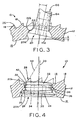
Figure 3 is a view similar toFigure 2 showing a bone screw in the aperture; -
Figure 4 is a view similar toFigure 2 showing a plug of the present invention in the aperture; -
Figure 5 is a distal plan view of a plug of the present invention; -
Figure 6 is a proximal plan view of the plug ofFigure 5 ; -
Figure 7 is a cross-sectional view of the plug ofFigure 6 , taken along line 7-7 ofFigure 6 ; -
Figure 7A is a partial cross-sectional view of the plug ofFigure 7 ; -
Figure 8 is a distal plan view of another plug of the present invention; -
Figure 9 is a distal plan view of yet another plug of the present invention; -
Figure 10 is a proximal plan view of the plug ofFigure 9 ; -
Figure 11 is a cross-sectional view of the plug ofFigure 10 , taken along line 11-11 ofFigure 10 ; -
Figure 11A is a partial cross-sectional view of the plug ofFigure 11 ; -
Figure 11B is a partial distal plan view of the plug ofFigure 11 ; -
Figure 12 is a distal plan view of still yet another plug of the present invention; -
Figure 13 is a proximal plan view of the plug ofFigure 12 ; -
Figure 14 is a cross-sectional view of the plug ofFigure 13 , taken along line 14-14 ofFigure 13 ; -
Figure 14A is a partial cross-sectional view of the plug ofFigure 14 ; and -
Figure 14B is a partial distal plan view of the plug ofFigure 14 . - Corresponding reference characters indicate corresponding parts throughout the several views. The exemplifications set out herein illustrate exemplary embodiments of the invention and such exemplifications are not to be construed as limiting the scope of the invention in any manner.
- Referring to
Figure 1 , an exemplary medical implant is shown in the form ofprosthetic acetabulum 10 of the type that is implanted within the acetabulum of a patient's pelvis during a partial or total hip arthroplasty procedure.Prosthetic acetabulum 10 generally provides a concave bearing surface that receives either the convex head of a femur or a convex prosthetic femoral head. Although the present invention is described herein in the form ofprosthetic acetabulum 10, the present invention is generally applicable to any type of medical implant having apertures that may be sealed after implantation of the implant system into the body. - Referring to
Figures 1-4 ,prosthetic acetabulum 10 may includeacetabular shell 12 and a liner (not shown).Acetabular shell 12 includes an exterior bone-contactingsurface 14 and aninterior receiving surface 16. Whenprosthetic acetabulum 10 includes a liner, receivingsurface 16 ofacetabular shell 12 is sized to receive and attach to the liner. The liner has a concave bearing surface that receives either the head of the femur or the prosthetic femoral head. If a separate liner is not utilized, receivingsurface 16 ofacetabular shell 12 itself may be designed as a bearing surface capable of receiving the head of the femur or a prosthetic femoral head. - Referring still to
Figures 1-4 , bone-contactingsurface 14 ofacetabular shell 12 is located opposite receivingsurface 16. Upon implantation into a patient, bone-contactingsurface 14 is positioned against the patient's pelvic bone. Various methods are available for securingacetabular shell 12 to the patient's pelvic bone, such as driving screws into the bone and applying adhesive, for example. Bone-contactingsurface 14 may further include a textured finish and/orteeth 18 to enhance the attachment betweenacetabular shell 12 and the patient's bone. The distance between bone-contactingsurface 14 and receivingsurface 16, or the thickness oracetabular shell 12, may be as small as approximately 1, 2, or 3 millimeters or as large as approximately 4, 5, or 6 millimeters. - Referring to
Figures 2-4 ,acetabular shell 12 includes at least oneaperture 20 that extends throughacetabular shell 12 from bone-contactingsurface 14 to receivingsurface 16. The length ofaperture 20 depends on the thickness ofacetabular shell 12, or the distance between bone-contactingsurface 14 and receivingsurface 16 ofacetabular shell 12.Acetabular shell 12 is designed to receivebone screw 100 withinaperture 20 for attachingacetabular shell 12 to the patient's bone.Aperture 20 may be defined betweenproximal wall 20a anddistal wall 20b, both of which are described in more detail below.Proximal wall 20a anddistal wall 20b surrounding aperture 20 are unthreaded to permitbone screw 100 to be oriented in various positions withinaperture 20. -
Proximal wall 20a ofaperture 20 is located near receivingsurface 16 ofacetabular shell 12. As shown inFigure 3 ,proximal wall 20a surroundsaperture 20 to provide a location forhead 102 ofbone screw 100 withinaperture 20.Proximal wall 20a definesaperture 20 that is essentially frusto-conical in shape, withaperture 20 narrowing as it extends away from receivingsurface 16 and toward bone-contactingsurface 14 ofacetabular shell 12. The size and shape ofproximal wall 20a permits head 102 ofbone screw 100 to be oriented in various positions withinaperture 20, as shown inFigure 3 . The narrowing ofaperture 20, in particular, preventshead 102 ofbone screw 100 from pulling out ofaperture 20. Therefore, the narrowing ofaperture 20 preventsacetabular shell 12 from separating from the patient's bone when secured withbone screw 100. -
Distal wall 20b ofaperture 20 is located near bone-contactingsurface 14 ofacetabular shell 12 and adjacent toproximal wall 20a ofaperture 20.Distal wall 20b definesaperture 20 that is essentially frusto-conical in shape, withaperture 20 widening as it extends toward bone-contactingsurface 14 and away from receivingsurface 16 ofacetabular shell 12. The widening ofaperture 20permits shaft 104 ofbone screw 100 to extend away fromacetabular shell 12 at various angles. Plugs can be designed to attach toacetabular shell 12 by expanding outwardly towarddistal wall 20b ofaperture 20. - Between
proximal wall 20a anddistal wall 20b,acetabular shell 12 includesannular ridge 22.Ridge 22 projects intoaperture 20 to define a narrowed portion ofaperture 20. As discussed above with reference toFigure 3 ,ridge 22 is provided to preventhead 102 ofbone screw 100 from pulling out ofaperture 20.Ridge 22 may have a thickness T as small as approximately 0.3, 0.4, or 0.5 millimeters or as large as approximately 0.6, 0.7, or 0.8 millimeters.Ridge 22 may define a narrowed portion ofaperture 20 having a diameter as small as approximately 4, 5, or 6 millimeters or as large as approximately 7, 8, or 9 millimeters - Referring to
Figure 4 , plug 24 is provided to coveraperture 20 ofacetabular shell 12 whenaperture 20 does not receive bone screw 100 (Figure 3 ).Plug 24 is configured to fit withinaperture 20 to prevent materials, such as bone debris and adhesive used to secure bone-contactingsurface 14 ofacetabular shell 12 to the patient's bone, from seeping throughaperture 20 and onto receivingsurface 16 ofacetabular shell 12. -
Plug 24 may be constructed of metal, such as titanium or a titanium alloy, polymer, or another biocompatible material. In an exemplary embodiment of the present invention, plug 24 is constructed of commercially pure titanium (cpTi), such as Protasul-Ti.Plug 24 may be manufactured by any method known in the art, such as molding. - Referring still to
Figure 4 , plug 24 includesproximal end 26,distal end 28, andlongitudinal axis 33 extending fromproximal end 26 todistal end 28. As used herein, "proximal" and "distal" are determined relative to a surgeon or another user, such thatdistal end 28 ofplug 24 is farther from the surgeon thanproximal end 26 ofplug 24 during use.Plug 24 is slightly frusto-conical in shape to mimic the shape ofaperture 20, and inparticular aperture 20 as defined withinproximal wall 20a. Near itsproximal end 26, plug 24 may have a diameter as small as approximately 6, 7, or 8 millimeters or as large as approximately 9, 10, or 11 millimeters.Plug 24 may narrow towarddistal end 28. Near itsdistal end 28, plug 24 may have a diameter as small as approximately 4, 5, or 6 millimeters or as large as approximately 7, 8, or 9 millimeters. -
Plug 24 further includeshead 30 located nearproximal end 26.Head 30 includes bore 34 configured to cooperate with a tool (not shown) for turningplug 24. In an exemplary embodiment of the present invention, bore 34 is hexagonal to receive a hex wrench, also known as an Allen wrench. -
Plug 24 further includesbody 32 extending fromhead 30 todistal end 28.Body 32 ofplug 24 includesexterior surface 36 that extends the length ofbody 32.Body 32 also includesthread 38 that projects fromexterior surface 36 and wraps helically aroundbody 32.Thread 38 is sized to engageridge 22 ofacetabular shell 12 whenplug 24 is positioned withinaperture 20. Therefore, adjacent threads are separated by a distance at least slightly exceeding the thickness ofridge 22. - Referring to
Figures 3-4 , unlikebone screw 100, which is driven into adjacent bone to secureacetabular shell 12 in place, plug 24 is not driven into the patient's bone. In an exemplary embodiment of the present invention, illustrated inFigure 4 , plug 24 is sized to avoid direct contact with the patient's bone.Distal end 28 ofplug 24 may be relatively flat or may protrude slightly, as shown inFigure 4 , to avoid protruding beyond bone-contactingsurface 14 ofacetabular shell 12, and in particular beyondteeth 18 on bone-contactingsurface 14 ofacetabular shell 12. Similarly, plug is sized to avoid direct contact with an acetabular liner (not shown) or a femoral head (not shown) received withinacetabular shell 12.Proximal end 26 ofplug 24 may be relatively flat to avoid protruding beyond receivingsurface 16 ofacetabular shell 12. As mentioned above, the distance between bone-contactingsurface 14 and receivingsurface 16 ofacetabular shell 12 may be as small as approximately 1, 2, or 3 millimeters or as large as approximately 4, 5, or 6 millimeters. In order forplug 24 to avoid protruding fromaperture 20 beyond bone-contactingsurface 14 and/or receivingsurface 16, plug 24 may be provided in a size corresponding to the thickness ofacetabular shell 12. Therefore, the distance betweenproximal end 26 anddistal end 28 ofplug 24 may be as small as approximately 1, 2, or 3 millimeters or as large as approximately 4, 5, or 6 millimeters. - Referring to
Figure 4 ,thread 38 is interrupted neardistal end 28 ofplug 24 by at least onenotch 42 indistal end 28 ofbody 32. In an exemplary embodiment, approximately one or two layers ofthread 38 are interrupted bynotch 42 indistal end 28 ofbody 32.Notch 42 is essentially an indentation in or cut-away fromdistal end 28 ofbody 32.Notch 42 may be located at least partially withintransverse plane 44.Transverse plane 44 extends transversely tolongitudinal axis 33, intersecting bothexterior surface 36 ofbody 32 anddistal end 28 ofbody 32. - For purposes of describing
notch 42 in more detail, plug 24 is shown divided into quadrants I, II, III, and IV inFigures 5-14 . These quadrants are illustrative only, as the position of the notch is not limited to the locations set forth below. - In the following embodiments of
plug 24, each notch 42'-42"' includes a respectivecentral portion 46'-46"', end portion 48'-48", and end portion 50'-50"'. End portions 48'-48" and end portions 50'-50"' are located on either side of the respectivecentral portions 46'-46"'. The intersections between transverse planes 44'-44"' anddistal end 28 of eachbody 32 forms distal intersections 52'-52"'. - According to an embodiment of the present invention, illustrated in
Figures 4-8 , notch 42' is located entirely within transverse plane 44', and notch 42' extends the length of distal intersection 52'. In this embodiment, transverse plane 44' may extend approximately 30 degrees fromlongitudinal axis 33 within quadrants I and IV. More specifically, transverse plane 44' extends fromexterior surface 36 ofbody 32 within quadrants I and IV todistal end 28 ofbody 32 within quadrants I and IV. Because notch 42' is located entirely within transverse plane 44',central portion 46' and end portions, 48' and 50', of notch 42' are all located within transverse plane 44'. Further, notch 42' extends the length of distal intersection 52' betweendistal end 28 ofbody 32 and transverse plane 44'. In this embodiment, transverse plane 44' is tangential tobody 32 along notch 42'. As illustrated, notch 42' is located within transverse plane 44', which is located within quadrants I and IV. However, notch 42' and transverse plane 44' could be located within a single quadrant or could span several quadrants. - According to another embodiment of the present invention, illustrated in
Figures 9-11 , notch 42" is located only partially withintransverse plane 44". In this embodiment,transverse plane 44" may extend approximately 15 degrees fromlongitudinal axis 33 within quadrants I and IV. (A secondtransverse plane 44" is located within quadrants II and III.) More specifically,transverse plane 44" within quadrants I and IV extends fromexterior surface 36 ofbody 32 within quadrants I and IV todistal end 28 ofbody 32 within quadrants I and IV. (Similarly,transverse plane 44" within quadrants II and III extends fromexterior surface 36 ofbody 32 within quadrants II and III todistal end 28 ofbody 32 within quadrants II and III.) Unlike notch 42' which is located entirely within transverse plane 44' (Figure 4 ), notch 42" curves towardexterior surface 36 ofbody 32. In an exemplary embodiment,central portion 46" ofnotch 42" is located withintransverse plane 44", while end portions, 48" and 50", ofnotch 42" curve away fromlongitudinal axis 33 and out oftransverse plane 44". As illustrated, notch 42" is located partially withintransverse plane 44", which is located within quadrants I and IV. (Asecond notch 42" is located within a secondtransverse plane 44", which is located within quadrants II and III.) However, eachnotch 42" andtransverse plane 44" could be located within a single quadrant or could span several quadrants. - According to yet another embodiment of the present invention, illustrated in
Figures 12- 14 , notch 42"' is located entirely within transverse plane 44''' and extends only partially the length ofdistal intersection 52"'. In this embodiment,transverse plane 44"' may extend approximately 15 degrees fromlongitudinal axis 33 within quadrants I and IV. (A secondtransverse plane 44"' is located within quadrants II and III.) More specifically,transverse plane 44"' within quadrants I and IV extends fromexterior surface 36 ofbody 32 within quadrants I and IV todistal end 28 ofbody 32 within quadrants I and IV. (Similarly, transverse plane 44''' within quadrants II and III extends fromexterior surface 36 ofbody 32 within quadrants II and III todistal end 28 ofbody 32 within quadrants II and III.) Like notch 42' (Figure 4 ), all ofnotch 42"' is located withintransverse plane 44"'. However, unlike notch 42' (Figure 4 ), notch 42"' does not extend the entire length ofdistal intersection 52"' betweendistal end 28 ofbody 32 andtransverse plane 44"'. More specifically,central portion 46"' and end portions, 48''' and 50"', are all located within transverse plane 44''', but end portions, 48''' and 50"', are not located at the edges of distal intersection 52''' within quadrants I and IV. (Similarly, end portions, 48''' and 50"', are not located at the edges ofdistal intersection 52"' within quadrants II and III.)
As illustrated, although transverse plane 44''' spans quadrants I and IV, notch 42" is located only within quadrant IV. (A second transverse plane 44''' spans quadrants II and III, but asecond notch 42"' is located only within quadrant II.) Eachnotch 42"' could, however, extend into multiple quadrants. - Referring to
Figures 8, 9 , and12 , plug 24 may include multiple notches. The notches may be spaced apart from one another in various arrangements. For example, the notches may be aligned symmetrically ondistal end 28 ofplug 24. As shown inFigure 9 ,notches 42" are located 180 degrees apart from one another ondistal end 28 ofplug 24. However, the notches need not be aligned symmetrically. As shown inFigure 8 , notches 42' are located approximately 120 degrees apart from one another ondistal end 28 ofplug 24. - Referring to
Figure 3 , a method is provided for coveringaperture 20 ofacetabular shell 12 withplug 24 whenaperture 20 does not receivebone screw 100.Acetabular shell 12 may be secured in place by drivingbone screw 100 throughapertures 20 inacetabular shell 12 and/or by applying adhesive betweenacetabular shell 12 and the patient's pelvic bone, for example. Depending on the surgeon's preference and/or the condition of the patient's pelvic bone, not allapertures 20 may receive bone screws. - Referring to
Figure 4 , the present method involves positioningplug 24 withinaperture 20 such that the unthreaded portion ofplug 24 is aligned withridge 22. More specifically, this step involves positioningplug 24 withinaperture 20, such as via press-fittingplug 24 intoaperture 20, withdistal end 28 ofplug 24 facing bone-contactingsurface 14 ofacetabular shell 12 and withproximal end 26 ofplug 24 facing receivingsurface 16 ofacetabular shell 12. In this position,head 30 ofplug 24 is accessible from receivingsurface 16 ofacetabular shell 12, whiledistal end 28 ofplug 24 extends intoaperture 20 and approachesridge 22. Asdistal end 28 ofplug 24 approachesridge 22 ofacetabular shell 12,ridge 22 ofacetabular shell 12 aligns withplug 24 alongnotch 42. Pressure may be applied toproximal end 26 ofplug 24 untilplug 24 engagesridge 22 alongnotch 42. It is within the scope of the present invention thatacetabular shell 12 may be provided withplug 24 already in this position. - Referring still to
Figure 4 , the present method further involves turningplug 24 so thatthread 38 engagesridge 22.Plug 24 need not be turned a full turn, or 360 degrees, to engageridge 22. This step involves using a tool, such as a hex wrench, that cooperates withbore 34 inhead 30 ofplug 24. In an exemplary embodiment of the present invention, whenplug 24 reaches its final position withinaperture 20, plug 24 essentially fillsaperture 20 to prevent materials, such as bone debris and adhesive, from seeping throughaperture 20 and onto receivingsurface 16 ofacetabular shell 12. Also in this exemplary embodiment, plug 24 is sized to fit almost entirely withinaperture 20, such thathead 30 onproximal end 26 ofplug 24 does not project beyond receivingsurface 16 ofacetabular shell 12 and such thatdistal end 28 ofplug 24 does not project beyond bone-contactingsurface 14 ofacetabular shell 12. - [0001] Advantageously, the present invention provides a robust design for
plug 24 that does not require bendable or movable parts to engageridge 22 ofacetabular shell 12. Also, plug 24 may be removed once inserted intoaperture 20, similar to a typical screw. In addition, plug 24 is capable of being secured within an unthreadedaperture 20 by engagingridge 22. Withoutnotch 42 inplug 24, a surgeon may struggle to engageridge 22 at all. Finally, plug 24 is designed to engageridge 22 while still being short enough in length to avoid projecting well beyond bone-contactingsurface 14 ofacetabular shell 12 and receivingsurface 16 ofacetabular shell 12. - According to an embodiment of the invention, the body of the plug may comprise titanium.
- A method of covering an aperture in a prosthetic implant, the prosthetic implant including an annular ridge projecting into the aperture and narrowing the aperture may comprise the step of implanting the prosthetic implant into a patient's pelvis.
- While this invention has been described as having preferred designs, the present invention can be further modified within the spirit and scope of this disclosure. This application is therefore intended to cover any variations, uses, or adaptations of the invention using its general principles. Further, this application is intended to cover such departures from the present disclosure as come within known or customary practice in the art to which this invention pertains and which fall within the limits of the appended claims.
Claims (15)
- A plug for covering an aperture in a prosthetic implant, the prosthetic implant including an annular ridge projecting into the aperture and narrowing the aperture, said plug comprising:a first end;a second end;a head located at the second end of the plug;a body extending between the head of the plug and the first end of the plug, said body comprising an exterior surface and a longitudinal axis;a thread that extends from the exterior surface of the body and wraps helically around the body; andat least one notch in the first end of the plug that interrupts the thread, the plug having a first position within the aperture in which the annular ridge aligns with the plug along the at least one notch and a second position within the aperture in which the thread engages the annular ridge.
- The plug of claim 1, further comprising a plurality of notches spaced across the first end of the plug.
- An implant system comprising:a prosthetic implant comprising:a bone-contacting surface;a receiving surface opposite the bone-contacting surface;at least one aperture extending a length between the bone-contacting surface and the receiving surface; anda plug sized to be received within the at least one aperture of the prosthetic implant, said plug comprising:a first end;a second end;a body extending between the second end of the plug and the first end of the plug a length substantially equivalent to the length of the aperture, said body comprising an exterior surface and a longitudinal axis;a thread that wraps helically around the body; andat least one notch in the body that interrupts the thread.
- The implant system of claim 3, wherein the prosthetic implant comprises a prosthetic acetabulum.
- The implant system of claim 3 or 4, wherein:the prosthetic implant includes an annular ridge projecting into the aperture to narrow the aperture; andthe thread of the plug is configured to engage said annular ridge.
- The implant system according to any of claims 3 to 5, wherein the first end of the plug and the second end of the plug are essentially flat, whereby the first end of the plug and the second end of the plug avoid projecting substantially beyond the aperture.
- The implant system according to any of claims 3 to 6 or the plug of claim 1 or 2, wherein:a plane extends transversely to the longitudinal axis of the body, said plane intersecting the first end of the plug to form an intersection; andthe at least one notch is located entirely within said plane.
- The implant system according to any of claims 3 to 6 or the plug of claim 1 or 2, wherein:a plane extends transversely to the longitudinal axis of the body, said plane intersecting the first end of the plug to form an intersection; andthe at least one notch spans a portion of said intersection.
- The implant system according to any of claims 3 to 6 or the plug of claim 1 or 2, wherein:a plane extends transversely to the longitudinal axis of the body, said plane intersecting the first end of the plug to form an intersection; andthe at least one notch is located partially within said plane.
- The implant system or the plug according to any of claims 7 to 9, wherein the plane extends approximately 30 degrees from the longitudinal axis of the body.
- The implant system or the plug according to any of claims 7 to 9, wherein the plane extends approximately 15 degrees from the longitudinal axis of the body.
- The implant system or the plug according to any of claims 7 to 11 , wherein the at least one notch comprises a central portion and two end portions, said central portion positioned within the plane and said two end portions positioned outside of the plane.
- A method of covering an aperture in a prosthetic implant, the prosthetic implant including an annular ridge projecting into the aperture and narrowing the aperture, said method comprising the steps of:providing a plug comprising a second end, a first end, a threaded portion, and an interrupted thread portion;positioning the plug within the aperture of the prosthetic implant to align the interrupted thread portion of the plug with the annular ridge; andturning the plug to engage the annular ridge with the threaded portion of the plug.
- The method of claim 13, wherein the interrupted thread portion of the plug comprises a notch in the first end of the plug.
- The method of claim 13 or claim 14, wherein the step of turning the plug comprises positioning the plug entirely within the aperture of the prosthetic implant, whereby the first end of the plug and the second end of the plug avoid projecting substantially beyond the aperture.
Applications Claiming Priority (1)
| Application Number | Priority Date | Filing Date | Title |
|---|---|---|---|
| US9346808P | 2008-09-02 | 2008-09-02 |
Publications (1)
| Publication Number | Publication Date |
|---|---|
| EP2158876A1 true EP2158876A1 (en) | 2010-03-03 |
Family
ID=41402790
Family Applications (1)
| Application Number | Title | Priority Date | Filing Date |
|---|---|---|---|
| EP09011276A Withdrawn EP2158876A1 (en) | 2008-09-02 | 2009-09-02 | Plug for covering screw holes in prostethic implants |
Country Status (2)
| Country | Link |
|---|---|
| US (1) | US20100057217A1 (en) |
| EP (1) | EP2158876A1 (en) |
Families Citing this family (5)
| Publication number | Priority date | Publication date | Assignee | Title |
|---|---|---|---|---|
| US8632600B2 (en) | 2007-09-25 | 2014-01-21 | Depuy (Ireland) | Prosthesis with modular extensions |
| US8535384B2 (en) | 2011-08-10 | 2013-09-17 | Biomet Manufacturing, Llc | Acetabular screw hole covers with porous coating |
| US9237953B2 (en) * | 2013-03-15 | 2016-01-19 | Depuy (Ireland) | Mechanical assembly of pegs to prosthesis |
| CN107979994B (en) | 2015-04-29 | 2020-05-26 | 拜欧米特制造有限责任公司 | Screw-threaded addible acetabular shell with an augmentation part |
| EP4166113A1 (en) | 2016-12-12 | 2023-04-19 | Zimmer, Inc. | Implants with frangible fastener port plugs |
Citations (6)
| Publication number | Priority date | Publication date | Assignee | Title |
|---|---|---|---|---|
| US4537185A (en) * | 1983-06-10 | 1985-08-27 | Denis P. Stednitz | Cannulated fixation screw |
| FR2748655A1 (en) * | 1996-05-14 | 1997-11-21 | Setiey Louis | Cotyloid implant cup |
| US5925048A (en) * | 1998-03-13 | 1999-07-20 | Osteomed | Bone screw |
| US5925077A (en) * | 1997-04-02 | 1999-07-20 | Biomet, Inc. | Apparatus and method for plugging holes in an acetabular shell component |
| DE19755246C1 (en) * | 1997-12-12 | 2000-03-30 | Aesculap Ag & Co Kg | Hip joint prosthesis socket has cup section and cap connected by tongue and groove fastenings |
| US20030163205A1 (en) * | 2002-02-27 | 2003-08-28 | Lawson Kevin Jon | Arthroplasty-prothesis cement restrictor |
Family Cites Families (6)
| Publication number | Priority date | Publication date | Assignee | Title |
|---|---|---|---|---|
| US5226917A (en) * | 1991-02-14 | 1993-07-13 | Smith & Nephew Richards Inc. | Acetabular prosthesis with anchoring pegs |
| ATE180655T1 (en) * | 1993-04-15 | 1999-06-15 | Sulzer Orthopaedie Ag | KIT FOR AN ARTIFICIAL JOINT POCKET, ESPECIALLY A HIP JOINT POCKET |
| ATE184179T1 (en) * | 1994-02-07 | 1999-09-15 | Sulzer Orthopaedie Ag | OUTER SHELL FOR AT LEAST A TWO-PUSHED JOINT SOCKET OF A HIP JOINT PROSTHESIS AND HIP JOINT PROSTHESIS WITH SUCH OUTER SHELL |
| AU2002245536A1 (en) * | 2001-02-26 | 2002-09-19 | Smith And Nephew, Inc. | Locking systems for implants |
| US7112222B2 (en) * | 2003-03-31 | 2006-09-26 | Depuy Spine, Inc. | Anterior lumbar interbody fusion cage with locking plate |
| US20060106384A1 (en) * | 2004-11-12 | 2006-05-18 | Reber Erik W | Intramedullary nail assembly |
-
2008
- 2008-12-17 US US12/337,208 patent/US20100057217A1/en not_active Abandoned
-
2009
- 2009-09-02 EP EP09011276A patent/EP2158876A1/en not_active Withdrawn
Patent Citations (6)
| Publication number | Priority date | Publication date | Assignee | Title |
|---|---|---|---|---|
| US4537185A (en) * | 1983-06-10 | 1985-08-27 | Denis P. Stednitz | Cannulated fixation screw |
| FR2748655A1 (en) * | 1996-05-14 | 1997-11-21 | Setiey Louis | Cotyloid implant cup |
| US5925077A (en) * | 1997-04-02 | 1999-07-20 | Biomet, Inc. | Apparatus and method for plugging holes in an acetabular shell component |
| DE19755246C1 (en) * | 1997-12-12 | 2000-03-30 | Aesculap Ag & Co Kg | Hip joint prosthesis socket has cup section and cap connected by tongue and groove fastenings |
| US5925048A (en) * | 1998-03-13 | 1999-07-20 | Osteomed | Bone screw |
| US20030163205A1 (en) * | 2002-02-27 | 2003-08-28 | Lawson Kevin Jon | Arthroplasty-prothesis cement restrictor |
Also Published As
| Publication number | Publication date |
|---|---|
| US20100057217A1 (en) | 2010-03-04 |
Similar Documents
| Publication | Publication Date | Title |
|---|---|---|
| US10507112B2 (en) | Implant anchoring device | |
| US10064734B2 (en) | Glenoid implant for a shoulder prosthesis, and surgical kit | |
| US4840632A (en) | Hip prosthesis | |
| US9351839B2 (en) | Acetabular cup fixation | |
| EP1802255B1 (en) | Unitary acetabular cup prosthesis with extension for deficient acetabulum | |
| US7044974B2 (en) | Hip prosthesis with a modular acetabular cup assembly | |
| US6355069B1 (en) | Bone engaging prosthesis | |
| US9168143B2 (en) | Cotyle comprising a sterile interface | |
| US5360452A (en) | Enhanced fixation system for a prosthetic implant | |
| EP2484315B1 (en) | Minimally invasive total hip replacement | |
| US4883491A (en) | Porous-coated artificial joints | |
| AU660146B2 (en) | Hip prosthesis | |
| EP0418301B1 (en) | Hip joint prosthesis | |
| US20070203583A1 (en) | Method and apparatus for aligning a taper lock connection | |
| US20040199258A1 (en) | Modular acetabular cup and anchoring screw for fixing a prosphetic implant such as said acetabular cup | |
| EP2754422A1 (en) | Augmented glenoid component | |
| CA2051793A1 (en) | Prothetic joint socket member | |
| EP2158876A1 (en) | Plug for covering screw holes in prostethic implants | |
| US8486151B2 (en) | Cotyloid element of a hip prosthesis, and total hip prosthesis comprising same | |
| JPH04503181A (en) | artificial hip joint | |
| US20060041315A1 (en) | Subtalar implant | |
| DE102004042502A1 (en) | Shoulder joint endoprothesis for human shoulders has an inlet side formed as a base in the structure of a rotation-symmetrical body | |
| EP2231071B1 (en) | Acetabular prosthesis |
Legal Events
| Date | Code | Title | Description |
|---|---|---|---|
| PUAI | Public reference made under article 153(3) epc to a published international application that has entered the european phase |
Free format text: ORIGINAL CODE: 0009012 |
|
| AK | Designated contracting states |
Kind code of ref document: A1 Designated state(s): AT BE BG CH CY CZ DE DK EE ES FI FR GB GR HR HU IE IS IT LI LT LU LV MC MK MT NL NO PL PT RO SE SI SK SM TR |
|
| AX | Request for extension of the european patent |
Extension state: AL BA RS |
|
| 17P | Request for examination filed |
Effective date: 20100326 |
|
| STAA | Information on the status of an ep patent application or granted ep patent |
Free format text: STATUS: THE APPLICATION IS DEEMED TO BE WITHDRAWN |
|
| 18D | Application deemed to be withdrawn |
Effective date: 20130403 |