EP2158445B1 - Method for the contact-free measurement of deformations of a surface of a measured object - Google Patents
Method for the contact-free measurement of deformations of a surface of a measured object Download PDFInfo
- Publication number
- EP2158445B1 EP2158445B1 EP08773793A EP08773793A EP2158445B1 EP 2158445 B1 EP2158445 B1 EP 2158445B1 EP 08773793 A EP08773793 A EP 08773793A EP 08773793 A EP08773793 A EP 08773793A EP 2158445 B1 EP2158445 B1 EP 2158445B1
- Authority
- EP
- European Patent Office
- Prior art keywords
- image
- individual
- deformation
- time window
- images
- Prior art date
- Legal status (The legal status is an assumption and is not a legal conclusion. Google has not performed a legal analysis and makes no representation as to the accuracy of the status listed.)
- Not-in-force
Links
- 238000000034 method Methods 0.000 title claims abstract description 51
- 238000005259 measurement Methods 0.000 title claims abstract description 48
- 230000003287 optical effect Effects 0.000 claims abstract description 20
- 238000006073 displacement reaction Methods 0.000 claims description 66
- 239000013598 vector Substances 0.000 claims description 64
- 238000012545 processing Methods 0.000 claims description 8
- 238000013519 translation Methods 0.000 claims description 4
- 230000014616 translation Effects 0.000 claims description 4
- 230000002123 temporal effect Effects 0.000 claims description 2
- 230000000875 corresponding effect Effects 0.000 description 8
- 238000012935 Averaging Methods 0.000 description 7
- 238000004364 calculation method Methods 0.000 description 7
- 230000006872 improvement Effects 0.000 description 7
- 230000008569 process Effects 0.000 description 6
- 230000003068 static effect Effects 0.000 description 5
- 238000012360 testing method Methods 0.000 description 4
- 230000008901 benefit Effects 0.000 description 3
- 230000008859 change Effects 0.000 description 3
- 238000012937 correction Methods 0.000 description 3
- 230000002349 favourable effect Effects 0.000 description 3
- 238000013459 approach Methods 0.000 description 2
- 230000015572 biosynthetic process Effects 0.000 description 2
- 238000011161 development Methods 0.000 description 2
- 239000000463 material Substances 0.000 description 2
- 239000011159 matrix material Substances 0.000 description 2
- 238000000691 measurement method Methods 0.000 description 2
- 230000010355 oscillation Effects 0.000 description 2
- 238000001454 recorded image Methods 0.000 description 2
- 238000012800 visualization Methods 0.000 description 2
- 238000009825 accumulation Methods 0.000 description 1
- 230000009286 beneficial effect Effects 0.000 description 1
- 230000032823 cell division Effects 0.000 description 1
- 230000006835 compression Effects 0.000 description 1
- 238000007906 compression Methods 0.000 description 1
- 230000002596 correlated effect Effects 0.000 description 1
- 238000005314 correlation function Methods 0.000 description 1
- 230000001627 detrimental effect Effects 0.000 description 1
- 238000012886 linear function Methods 0.000 description 1
- 238000012417 linear regression Methods 0.000 description 1
- 238000003672 processing method Methods 0.000 description 1
- 230000000717 retained effect Effects 0.000 description 1
- 238000001228 spectrum Methods 0.000 description 1
- 238000004154 testing of material Methods 0.000 description 1
- 230000001960 triggered effect Effects 0.000 description 1
Images


Classifications
-
- G—PHYSICS
- G01—MEASURING; TESTING
- G01B—MEASURING LENGTH, THICKNESS OR SIMILAR LINEAR DIMENSIONS; MEASURING ANGLES; MEASURING AREAS; MEASURING IRREGULARITIES OF SURFACES OR CONTOURS
- G01B11/00—Measuring arrangements characterised by the use of optical techniques
- G01B11/16—Measuring arrangements characterised by the use of optical techniques for measuring the deformation in a solid, e.g. optical strain gauge
Definitions
- the invention relates to a method for the contactless measurement of deformations of a surface of a measurement object, wherein at least a first image of the measurement object and in a first time window, in which the measurement object is subjected to a first mechanical stress, by means of an image detector constructed of a plurality of ordered pixels a second time window in which the measurement object is subjected to a second mechanical stress, at least a second image of the measurement object is taken and the recorded images are processed by a data processing unit to generate a deformation field which assigns deformation variables representing regions of the measurement object stress-induced deformations.
- a component to be tested here referred to as a measurement object, a mechanical stress (English: stress) suspended.
- a mechanical stress English: stress
- two different time windows one of which, for example, may be one before and one after applying the mechanical tension or both separated in time during the application of the mechanical tension, at least two images of the Measured object recorded.
- An image is understood here to be an ordered data matrix, with each matrix entry corresponding to the measurement result of a pixel of an image detector.
- image detectors are typically CCD cameras, CID cameras or similar devices in question.
- a comparison of the images taken in the first time window and the second time window for each area of the surface of the measurement object provides a translation caused by the applied voltage, which may be different for different areas. If one assigns a vector representing the translation of the respective area to each of these areas, one obtains a displacement vector field.
- a displacement vector field typically serves as the basis for calculating a differential strain field representing the local strain quantities for each region of the target surface.
- the term elongation is understood here as meaning its different forms, extension, compression, shear, rotation, “swirl”, “shear”, etc., for which definitions mathematically formulated are known to the person skilled in the art.
- the differential strain field is typically determined from the difference vectors of adjacent displacement vectors of the displacement vector field.
- an expansion field can be calculated directly, ie without the detour via the calculation of a displacement vector field, from the images recorded in the time windows.
- a deformation field built up from deformation variables, the deformation variables, depending on the application, being the displacement variables, in particular displacement vectors, or the expansion variables.
- the deformation variables may be scalars, vectors or tensors of higher order.
- the displacement vector field For determining the displacement vector field, several methods are known. Particularly favorable is the so-called cross-correlation method.
- an image recorded in the first time window is subdivided into a number of image cells.
- the image cells may be generated as a uniform grid distributed over the image geometry. Note that the image cells are based solely on the image geometry and not on the data content of the image. The same image cell division is made for an image taken in the second time window.
- the respective corresponding image cells of both images are subsequently linked by a two-dimensional cross-correlation, preferably along the grating axes designated as x and y.
- the maximum value of such a cross-correlation function provides the displacement vector for the image cell and thus for the area of the measurement object surface represented by the image cell of the first image.
- the cross-correlation allows a subpixel accurate determination of the displacement vectors.
- an accuracy of the displacement vector of 0.01 to 0.05 pixels can be achieved with known methods.
- By enlarging the cells can be another Achieve accuracy improvement.
- this increases the distance between the individual vectors of the displacement vector field, so that in individual cases a balance must be made between the accuracy of the individual vectors and the resolution of the vector field.
- known methods reach their limits.
- a true resolution improvement can be achieved by a targeted "shake".
- a plurality of individual images are taken, wherein the detector is slightly offset between the individual images relative to the measurement object.
- the offset preferably takes place by an offset of the order of magnitude of a fraction of a pixel up to a few pixels, but an offset by an integer multiple of a pixel is not expedient.
- the displacement of the detector is perpendicular to the optical Axis, ie parallel to the detector surface. In the context of the present application, this is understood to mean that the offset must have at least one component parallel to the detector surface; an (additional) slight offset parallel to the optical axis is harmless.
- a method for measuring a deformation field in which a sample is picked up in a reference state and in a stress-induced deformation state with an image detector.
- test points are identified by means of cross-correlation and the distances of the test points to a reference point are determined. Comparison of the distances in the reference image with those in the image of the deformed sample provides the deformation image, in particular the displacement vector field.
- None of the last three mentioned methods contains an approach to improving the accuracy of the determination of deformation quantities compared to the previously described methods.
- the deformation field is preferably a displacement vector field which assigns the regions of the measurement object stress-induced translations.
- the pairwise processing of the single images of the first and second time windows is done as a picture cell-wise, two-dimensional cross-correlation of the respective image data.
- the method of the present invention is not limited to the cross-correlation as a processing method of the single images.
- a displacement vector determined according to the invention can serve as the basis for generating an expansion field which assigns strain values representing stress-induced strains of these regions to the regions of the measurement object.
- differences of adjacent displacement quantities and / or variables derived from such differences are calculated.
- from the differences of individual Vector components are determined to the corresponding vector components of different neighboring vectors strain tensors, from whose components scalar strain quantities can be calculated.
- ⁇ xy / ⁇ y ⁇ ⁇ x .
- ⁇ yx / ⁇ x ⁇ ⁇ ⁇ y .
- ⁇ yy / ⁇ y ⁇ ⁇ ⁇ y
- ⁇ x and ⁇ y respectively, are a difference of the x and y components of the displacement vector and / ⁇ x ⁇ respectively.
- / ⁇ y ⁇ means the partial derivative in the x or y direction.
- the strains of strain and shear which are generally of interest, are defined as ⁇ xx + ⁇ yy and 1 ⁇ 2 ( ⁇ xy + ⁇ yx ). In the discrete (because digital) case present here, corresponding differences or difference quotients can be used instead of the differentials.
- the deformation field is a strain field which assigns strain-induced strains of these areas to the regions of the measurement object.
- the pairwise processing of the images from the two time windows can also lead directly to a strain field, often with a simultaneous calculation of the displacement vector field.
- the measuring object is of an optical nature, ie it must relate to an offset of the image of the measurement object projected onto the image detector relative to the detector surface. This can be done for example by a mechanical displacement of the image detector itself, for example by means of electromechanical and / or piezoelectric actuators. Alternatively, however, it is also possible to generate the optical offset by varying an optical medium between the detector and the measurement object.
- the optical displacements of the image detector between the images of the individual images of a time window modulo a pixel expansion is uniformly distributed over a pixel area.
- the displacements which are preferably, but not necessarily, smaller than the extent of a pixel in the displacement direction, are distributed as evenly as possible in the summary.
- one-component oscillation of the image detector would result in an undesirable accumulation of the obtained offsets on a line oriented in the direction of oscillation.
- "uniformly distributed” is to be understood here in the statistical sense and means evenly distributed within the standard deviation.
- the amount of offset depends only on the fraction of a pixel extent that exceeds an integer multiple, including zero. This will be expressed mathematically with the phrase "modulo".
- the optical displacement can be of any desired, in particular random or pseudorandom nature.
- actuators which mechanically offset the image detector could be triggered at random, or in the case of an optical displacement by varying the optical medium between the detector and the object to be measured, for example a rotating wedge disk or a similarly simple device could be used.
- the measurement object is static during each time window.
- This first mechanical stress can be zero, for example.
- the second time window is favorably positioned so that the measurement object is likewise subjected to a static, but with a second mechanical stress different from the first mechanical stress.
- advantageous conditions are not feasible in every case. For example, it is possible for one of the created mechanical stresses, in particular the second mechanical stress, during the second time window is so large that the object under test changes dynamically during the time window.
- the measured object changes dynamically during both time windows, wherein, for example, during both time windows the same mechanical stress exceeding a yield point of the measuring object material is applied.
- a regression is determined by a histogram for determining the result deformation field from the individual deformation fields, which determines the deformation variables of the individual deformation fields assigned to a region of the measurement object over the time of recording the individual deformation fields. Represents images of a time window.
- the individual displacement vector fields determined by pairwise processing, in particular cross correlation, of two individual images of different time windows are arranged in a histogram which is the size (and optionally the direction) of each displacement vector of the individual displacement vector fields over the Time of recording the Compensation-requiring time window associated single images. If, for example, 10 individual images of the first time window at constant elongation are correlated with 10 individual images of the second time window with changing strain, this results in 100 individual displacement vector fields.
- a histogram can then be created on the x-axis, for example, the recording times of the individual images of the second time window are plotted, ie, the axis is divided into 10 sections.
- 10 histogram points represented the sizes of the single displacement vectors plotted on the y-axis resulting from the correlations with the 10 single images of the first time window. If one places a (in the simplest case linear) regression through this histogram, this represents the global displacement or deformation of the measurement object during the second time window.
- the regression per se is regarded here as averaging and a value representing the regression, eg the value of the regression curve at a middle time of the time window T2, can be used as the result size for the affected image cell.
- the inventive method is not limited to these. Rather, it is possible to calculate the corresponding values or vector fields also on three-dimensionally extended surfaces.
- at least two spatially offset image detectors are used whose output data in for the It will be obvious to those skilled in the art in light of the above explanations.
- FIG. 1 schematically shows four such staggered single images.
- the detector such as a CCD camera or its chip, are offset by controllable actuators between the individual shots.
- optical displacement it is also possible, for optical displacement, to use variations of an optical medium for offsetting the image of the measurement object onto the detector.
- FIG. 2 schematically shows the preferred order of magnitude of the offset. This is favorably only a fraction of a detector pixel, for example 1/2, 1/3, 1/4 ...
- the offset by more than one pixel is basically possible, but should preferably not exceed a few pixels.
- An offset by a full-line multiple of a pixel is basically harmless, but does not contribute to the resolution improvement.
- the offsets of a time window (each modulo a pixel extent) should be equally distributed over a pixel area.
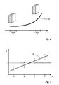
- FIG. 3 schematically shows the typical sequence of a measurement according to the inventive method.
- the curve 10 schematically shows the course of a global deformation of the measurement object due to an applied mechanical stress.
- the measurement object passes by the application of the mechanical stress of a first static state in a second static state.
- time windows T1 and T2 are defined, during which a plurality of individual images with the optical offset explained above are taken each other.
- a single image is taken in each time window at times t1, t2, t3 and t4 so that 4 individual images resulted from each time window.
- FIG. 4 schematically illustrates the generation of a displacement vector field from two images originating from different time windows.
- the images are marked with the abbreviation of the corresponding time window T1 or T2.
- Each image is subdivided into a plurality of image cells 12 which respectively orient themselves to the geometry of the image and not to the image information captured in the image.
- a typical subdivision into image cells is the subdivision of the entire image into adjoining blocks each of, for example, 20 x 20 pixels.
- image information is in FIG. 4 in the marked image cell 12, a pattern 14, consisting of three points drawn. These points represent surface points of the measurement object. It should be noted at this point that although it is possible, but not mandatory, to coat the surface of the measurement object with a defined pattern of marking points. Especially at Use of the cross-correlation method is often sufficient contrast differences resulting from the natural surface structure of the measurement object.
- FIG. 4 illustrated cross-correlation method is basically known in the art.
- FIG. 5 shows schematically the improvement according to the invention of the known method.
- each image t1, t2, t3 and t4 recorded in the time window T1 is linked to each of the images tl-4 recorded in the time window T2, in particular cross-correlated, resulting in a multiplicity of individual displacement vector fields 18.
- FIG. 5 resorting to FIG. 3 Assuming that 4 individual images were taken in each time window T1, T2, 16 single displacement vector fields 18 result in the illustrated example. An averaging of these individual vector fields 18 yields a result displacement vector field 20 which significantly improves the accuracy of the local Displacement vectors 22 while maintaining the image cell size.
- FIG. 6 shows in the same representation as FIG. 3 the case that the measurement object is not in a stationary state at least in the second time window T2.
- the calculation of the result shift vector field is preceded by a correction of the single displacement vector fields or the conventional averaging (eg arithmetic mean formation) is replaced by a more complex type of averaging, such as regression.
- FIG. 7 A particularly advantageous method for determining a suitable correction quantity is in FIG. 7 shown.
- a histogram is generated for each image cell 12, as in FIG. 7 shown.
- the entries of the histogram correspond to the individual displacement vectors 16 of the corresponding image cell 12 from all the individual displacement vector fields 18.
- the abscissa of the histogram shows the times during the second time window T2, to which the individual images t1, t2, t3 and t4 have been added were.
- the ordinate indicates the amount of the respective local displacement vector 16. Note that in FIG. 7 For reasons of clarity, a representation of the direction of the local displacement vectors 16 has been dispensed with. In fact, all information contained in the local displacement vectors 16 can be stored in one represent multidimensional histogram.
- the histogram entries are shown in 4 clusters. Whether a cluster formation or another distribution actually occurs depends in the concrete case of application, for example, on whether the measurement object is in a non-stationary state in only one or both time windows and on the relation of the optical displacement of the individual images to the one Magnitude of the compensated, global shift or deformation.
- a regression 24 through the histogram which in the present case is represented as a linear regression, can serve as the basis for calculating an averaged quantity or as a compensation variable. In particular, it may be useful, as in the illustrated embodiment, to select as the average size that point on the regression line 24 which corresponds approximately to the middle of the time window T1.
- the result shift vector field generated according to the invention can serve as the basis for the calculation of further variables.
- a differential strain field can be determined from the difference vectors of adjacent displacement vectors in the result shift vector field.
Landscapes
- Physics & Mathematics (AREA)
- General Physics & Mathematics (AREA)
- Length Measuring Devices By Optical Means (AREA)
- Length Measuring Devices With Unspecified Measuring Means (AREA)
Abstract
Description
Die Erfindung betrifft ein Verfahren zur berührungslosen Messung von Verformungen einer Oberfläche eines Messobjektes, wobei mittels eines aus einer Mehrzahl geordneter Pixel aufgebauten Bilddetektors in einem ersten Zeitfenster, in dem das Messobjekt mit einer ersten mechanischen Spannung beaufschlagt ist, wenigstens ein erstes Bild des Messobjektes und in einem zweiten Zeitfenster, in dem das Messobjekt mit einer zweiten mechanischen Spannung beaufschlagt ist, wenigstens ein zweites Bild des Messobjektes aufgenommen wird und die aufgenommenen Bilder zur Erzeugung eines Verformungsfeldes, das Bereichen des Messobjektes spannungsinduzierte Verformungen repräsentierende Verformungsgrößen zuordnet, von einer Datenverarbeitungseinheit miteinander verarbeitet werden.The invention relates to a method for the contactless measurement of deformations of a surface of a measurement object, wherein at least a first image of the measurement object and in a first time window, in which the measurement object is subjected to a first mechanical stress, by means of an image detector constructed of a plurality of ordered pixels a second time window in which the measurement object is subjected to a second mechanical stress, at least a second image of the measurement object is taken and the recorded images are processed by a data processing unit to generate a deformation field which assigns deformation variables representing regions of the measurement object stress-induced deformations.
Derartige Verfahren finden vielfach Einsatz z.B. im Bereich der Materialprüfung. Dabei wird ein zu prüfendes Bauteil, hier als Messobjekt bezeichnet, einer mechanischen Spannung (engl.: stress) ausgesetzt. In zwei unterschiedlichen Zeitfenstern, von denen beispielsweise eines vor und eines nach Anlegen der mechanischen Spannung oder beide zeitlich getrennt während der Beaufschlagung mit der mechanischen Spannung liegen können, werden wenigstens zwei Bilder des Messobjektes aufgenommen. Unter einem Bild wird hier eine geordnete Datenmatrix verstanden, wobei jeder Matrixeintrag dem Messergebnis eines Pixels eines Bilddetektors entspricht. Als Bilddetektoren kommen typischerweise CCD-Kameras, CID-Kameras oder ähnliche Vorrichtungen infrage.Such methods are often used, for example in the field of material testing. In this case, a component to be tested, here referred to as a measurement object, a mechanical stress (English: stress) suspended. In two different time windows, one of which, for example, may be one before and one after applying the mechanical tension or both separated in time during the application of the mechanical tension, at least two images of the Measured object recorded. An image is understood here to be an ordered data matrix, with each matrix entry corresponding to the measurement result of a pixel of an image detector. As image detectors are typically CCD cameras, CID cameras or similar devices in question.
Typischer Weise liefert ein Vergleich der im ersten Zeitfenster und im zweiten Zeitfenster aufgenommenen Bilder für jeden Bereich der Oberfläche des Messobjektes eine durch die angelegte Spannung verursachte Translation, die für unterschiedliche Bereiche unterschiedlich sein kann. Ordnet man jedem dieser Bereiche einen die Translation des jeweiligen Bereichs repräsentierenden Vektor zu, erhält man ein Verschiebungsvektorfeld. Ein solches Verschiebungsvektorfeld dient typischerweise als Grundlage der Berechnung eines differentiellen Dehnungsfeldes, welches die lokale Dehnungsgrößen für jeden Bereich der Messobjektoberfläche repräsentiert. Unter dem Begriff der Dehnung werden hier seine unterschiedlichen Ausprägungen, Streckung, Stauchung, Scherung, Rotation, "Swirl", "Shear" etc. verstanden, für die dem Fachmann mathematisch formulierte Definitionen bekannt sind. Da sich die Dehnungsgrößen mathematisch aus der räumlichen Ableitung der Verschiebung jedes Oberflächenpunktes ergeben, wird das differentielle Dehnungsfeld typischerweise aus den Differenzvektoren benachbarter Verschiebungsvektoren des Verschiebungsvektorfeldes ermittelt. Es existieren jedoch auch Verfahren, bei denen ein Dehnungsfeld unmittelbar, d.h. ohne den Umweg über die Berechnung eines Verschiebungsvektorfeldes, aus den in den Zeitfenstern aufgenommenen Bildern berechnet werden kann. Um beide Verfahrensvarianten abzudecken, wird hier allgemein von einem aus Verformungsgrößen aufgebauten Verformungsfeld gesprochen, wobei als Verformungsgrößen je nach Anwendungsfall die Verschiebungsgrößen, insbesondere Verschiebungsvektoren, oder die Dehnungsgrößen bezeichnet sind. Je nach Mess- bzw. Berechnungsverfahren kann es sich bei den Verformungsgrößen um Skalare, Vektoren oder Tensoren höherer Ordnung handeln.Typically, a comparison of the images taken in the first time window and the second time window for each area of the surface of the measurement object provides a translation caused by the applied voltage, which may be different for different areas. If one assigns a vector representing the translation of the respective area to each of these areas, one obtains a displacement vector field. Such a displacement vector field typically serves as the basis for calculating a differential strain field representing the local strain quantities for each region of the target surface. The term elongation is understood here as meaning its different forms, extension, compression, shear, rotation, "swirl", "shear", etc., for which definitions mathematically formulated are known to the person skilled in the art. Since the strain magnitudes result mathematically from the spatial derivative of the displacement of each surface point, the differential strain field is typically determined from the difference vectors of adjacent displacement vectors of the displacement vector field. However, there are also methods in which an expansion field can be calculated directly, ie without the detour via the calculation of a displacement vector field, from the images recorded in the time windows. To both Covering process variants is generally referred to here by a deformation field built up from deformation variables, the deformation variables, depending on the application, being the displacement variables, in particular displacement vectors, or the expansion variables. Depending on the measurement or calculation method, the deformation variables may be scalars, vectors or tensors of higher order.
Zur Ermittlung des Verschiebungsvektorfeldes sind mehrere Verfahren bekannt. Besonders günstig ist das sogenannte Kreuzkorrelationsverfahren. Hierzu wird ein im ersten Zeitfenster aufgenommenes Bild in eine Anzahl von Bildzellen unterteilt. Die Bildzellen können beispielsweise als ein gleichmäßiges, über die Bildgeometrie verteiltes Gitter erzeugt werden. Man beachte, dass sich die Bildzellen allein an der Bildgeometrie und nicht an dem Dateninhalt des Bildes orientieren. Dieselbe Bildzelleneinteilung wird für ein im zweiten Zeitfenster aufgenommenes Bild vorgenommen. Im Anschluss werden die jeweils korrespondierenden Bildzellen beider Bilder durch eine zweidimensionale Kreuzkorrelation, vorzugsweise entlang der als x und y bezeichneten Gitterachsen verknüpft. Der Maximalwert einer solchen Kreuzkorrelationsfunktion liefert den Verschiebungsvektor für die Bildzelle und somit für den von der Bildzelle des ersten Bildes repräsentierten Bereich der Messobjektoberfläche.For determining the displacement vector field, several methods are known. Particularly favorable is the so-called cross-correlation method. For this purpose, an image recorded in the first time window is subdivided into a number of image cells. For example, the image cells may be generated as a uniform grid distributed over the image geometry. Note that the image cells are based solely on the image geometry and not on the data content of the image. The same image cell division is made for an image taken in the second time window. The respective corresponding image cells of both images are subsequently linked by a two-dimensional cross-correlation, preferably along the grating axes designated as x and y. The maximum value of such a cross-correlation function provides the displacement vector for the image cell and thus for the area of the measurement object surface represented by the image cell of the first image.
Die Kreuzkorrelation erlaubt eine subpixelgenaue Bestimmung der Verschiebungsvektoren. Bei Wahl der Zellengröße von z.B. 20 x 20 Pixel ist mit bekannten Methoden eine Genauigkeit des Verschiebungsvektors von 0,01 bis 0,05 Pixel realisierbar. Durch Vergrößerung der Zellen lässt sich eine weitere Genauigkeitsverbesserung erreichen. Hierdurch vergrößert sich jedoch der Abstand zwischen den einzelnen Vektoren des Verschiebungsvektorfeldes, sodass im Einzelfall eine Abwägung zwischen der Genauigkeit der Einzelvektoren und der Auflösung des Vektorfeldes getroffen werden muss. In vielen Fällen ist jedoch die Verbesserung der Bestimmungsgenauigkeit der Verschiebungsvektoren unter Beibehaltung einer hohen Auflösung des Vektorfeldes wünschenswert. Hier stoßen bekannte Verfahren an ihre Grenzen.The cross-correlation allows a subpixel accurate determination of the displacement vectors. When choosing the cell size of, for example, 20 x 20 pixels, an accuracy of the displacement vector of 0.01 to 0.05 pixels can be achieved with known methods. By enlarging the cells can be another Achieve accuracy improvement. However, this increases the distance between the individual vectors of the displacement vector field, so that in individual cases a balance must be made between the accuracy of the individual vectors and the resolution of the vector field. However, in many cases, it is desirable to improve the accuracy of determination of the displacement vectors while maintaining a high resolution of the vector field. Here known methods reach their limits.
Analoges gilt auch für Fälle, in denen eine andere Art der Verarbeitung der Einzel-Bilder zu einem Verformungsfeld gewählt wird, beispielsweise für Verfahren, die direkt zu einem Dehnungsfeld führen.The same applies analogously to cases in which a different type of processing of the individual images is selected as a deformation field, for example for processes which lead directly to a strain field.
Zur Qualitätsverbesserung einzelner Bilder sind aus dem Bereich der digitalen Fotografie unterschiedliche Verfahren bekannt. Im einfachsten Fall können mehrere Bilder desselben Objektes aufgenommen und miteinander gemittelt werden. Hierdurch kann insbesondere das Detektorrauschen reduziert werden.To improve the quality of individual images, different methods are known from the field of digital photography. In the simplest case, multiple images of the same object can be recorded and averaged together. As a result, in particular the detector noise can be reduced.
Eine echte Auflösungsverbesserung kann durch ein gezieltes "Verwackeln" erreicht werden. Hierzu werden eine Mehrzahl von Einzel-Bildern aufgenommen, wobei zwischen den einzelnen Aufnahmen der Detektor relativ zum Messobjekt geringfügig versetzt wird. Die Versetzung erfolgt vorzugsweise um einen Versatz der Größenordnung eines Bruchteils eines Pixels bis hin zu wenigen Pixeln, wobei jedoch eine Versetzung um ein ganzzeiliges Vielfaches eines Pixels nicht zielführend ist. Die Versetzung des Detektors erfolgt senkrecht zur optischen Achse, d.h. parallel zur Detektorfläche. Dies ist im Rahmen der vorliegenden Anmeldung so zu verstehen, dass die Versetzung wenigstens eine Komponente parallel zur Detektorfläche aufweisen muss; eine (zusätzliche) geringfügige Versetzung parallel zur optischen Achse ist unschädlich. Aus der aufgenommenen Bildserie und der Information über die Versetzung lässt sich dann mit bekannten Entfaltungsmethoden ein Ergebnisbild mit Subpixelauflösung berechnen. Da der Entfaltungsalgorithmus jedoch empfindlich gegenüber Rauschen ist, kann man mit diesem Verfahren meist nur eine Auflösungsverbesserung um einen Faktor 2 bis 4 erzielen.A true resolution improvement can be achieved by a targeted "shake". For this purpose, a plurality of individual images are taken, wherein the detector is slightly offset between the individual images relative to the measurement object. The offset preferably takes place by an offset of the order of magnitude of a fraction of a pixel up to a few pixels, but an offset by an integer multiple of a pixel is not expedient. The displacement of the detector is perpendicular to the optical Axis, ie parallel to the detector surface. In the context of the present application, this is understood to mean that the offset must have at least one component parallel to the detector surface; an (additional) slight offset parallel to the optical axis is harmless. From the recorded image series and the information about the offset, a result image with subpixel resolution can then be calculated using known unfolding methods. However, since the deconvolution algorithm is sensitive to noise, it is usually only possible to achieve a resolution improvement by a factor of 2 to 4 with this method.
Das oben geschilderte Verfahren zur Ermittlung eines Verschiebungsvektorfeldes würde daher von der Anwendung des gezielten "Verwackelns" auf die miteinander zu verarbeitenden Bilder des ersten und des zweiten zeitfensters nur geringfügig profitieren.The above-described method for determining a displacement vector field would therefore benefit only marginally from the application of the targeted "blurring" to the images of the first and the second time window to be processed with one another.
Aus der
Ein ähnliches Verfahren ist aus der
Aus der
Keines der drei letztgenannten Verfahren enthält gegenüber den zuvor beschriebenen Verfahren einen Ansatz zur Verbesserung der Genauigkeit der Ermittlung von Verformungsgrößen.None of the last three mentioned methods contains an approach to improving the accuracy of the determination of deformation quantities compared to the previously described methods.
Es ist die Aufgabe der vorliegenden Erfindung, ein gattungsgemäßes Verfahren derart zu verbessern, dass die Genauigkeit, mit der die Verformungsgrößen ermittelt werden, unter Beibehaltung der Auflösung des Verformungsfeldes gesteigert wird.It is the object of the present invention to improve a generic method such that the accuracy with which the deformation variables are determined, while maintaining the resolution of the deformation field is increased.
Diese Aufgabe wird in Verbindung mit den Merkmalen des Oberbegriffs von Anspruch 1 dadurch gelöst, dass
- in jedem der Zeitfenster in zeitlicher Folge eine Mehrzahl von Einzel-Bildern aufgenommen werden, wobei zwischen je zwei Einzel-Bildaufnahmen der Bilddetektor relativ zum Messobjekt und parallel zu seiner Detektorfläche um einen optischen Versatz der Größe eines Bruchteils eines Pixels bis zu wenigen Pixeln versetzt wird,
- die Einzel-Bilder des ersten Zeitfensters paarweise mit den Einzel-Bildern des zweiten Zeitfensters zur Erzeugung eines Satzes von Einzel-Verformungsfeldern verarbeitet werden und
- als Ergebnis-Verformungsfeld eine Mittelung der Einzel-Verformungsfelder berechnet wird.
- a plurality of individual images are recorded in temporal sequence in each of the time windows, wherein between two individual image recordings the image detector relative to the measurement object and parallel to its detector surface by a offset from the size of a fraction of a pixel to a few pixels,
- the single images of the first time window are processed in pairs with the single images of the second time window to produce a set of single deformation fields, and
- as result-deformation field an average of the individual deformation fields is calculated.
Anstatt also durch gezieltes "Verwackeln" und anschließende Entfaltung auflösungsverbesserte Bilder aus dem ersten Zeitfenster und dem zweiten Zeitfenster miteinander z.B. durch Kreuzkorrelation zu verarbeiten, wird erfindungsgemäß vorgeschlagen, wie auch beim gezielten "Verwackeln" in jedem Zeitfenster mehrere Einzel-Bilder aufzunehmen, diese jedoch direkt und paarweise miteinander zu verarbeiten. Hieraus resultiert eine Vielzahl von Einzel-Verformungsfeldern, die anschließend zur Bestimmung des Ergebnis-Verformungsfeldes miteinander gemittelt werden. Eine separate Entfaltung entfällt somit. Dabei ist zu beachten, dass der Begriff der "Mittelung" hier weit zu verstehen ist und neben dem arithmetischen Mittel auch komplexere Formen der Mittelung, z.B. eine Regression umfasst.Thus, instead of deliberately "blurring" and then unfolding, resolution enhanced images from the first time window and the second time window, e.g. to process by cross-correlation is proposed according to the invention, as well as the targeted "shake" in each time window to take a plurality of single images, but to process them directly and in pairs with each other. This results in a plurality of individual deformation fields, which are then averaged together to determine the result-deformation field. A separate development is thus eliminated. It should be noted that the term "averaging" is to be understood here broadly and in addition to the arithmetic mean also more complex forms of averaging, e.g. includes a regression.
Dieser Ansatz erscheint zunächst überraschend, da weder die mit dem "Verwackeln" verbundene Faltung der Daten noch die typischerweise zur Verarbeitung der Paare von Einzel-Bildern verwendete Kreuzkorrelation lineare Funktionen sind, die eine Qualitätsverbesserung durch Mittelung erwarten lassen würden. Gleichwohl hat sich gezeigt, dass mit dem erfindungsgemäßen Verfahren eine Genauigkeitsverbesserung der Bestimmung der Verformungsgrößen des Ergebnis-Verformungsfeldes um einen Faktor 10 bei beibehaltener Bildzellengröße, d.h. Auflösung des Ergebnis-Verformungsfeldes, möglich ist. In Bezug auf das weiter oben erwähnte Beispiel einer Bildzellenwahl von 20 x 20 Pixel bedeutet dies, dass beispielsweise Verschiebungsvektoren mit eine Genauigkeit von bis zu 0,001 Pixel bestimmt werden können, wobei in der Regel nur die hieraus abgeleiteten differentiellen Dehnungsgrößen von Interesse sind, die jedoch ebenfalls mit deutlich verbesserter Genauigkeit berechenbar sind. Dies stellt eine wesentliche Qualitätsverbesserung gegenüber dem bekannten Verfahren dar.This approach seems surprising at first, as neither the convolution-linked convolution nor the cross-correlation typically used to process the pairs of single images are linear functions that would be expected to improve quality by averaging. Nevertheless, it has been shown that with the method according to the invention an improvement in the accuracy of the determination of the deformation quantities of the result deformation field by one
Bevorzugt ist das Verformungsfeld ein Verschiebungsvektorfeld, welches den Bereichen des Messobjektes spannungsinduziert Translationen zuordnet. Günstiger Weise erfolgt, wie erwähnt, die paarweise Verarbeitung der Einzel-Bilder des ersten und des zweiten Zeitfensters als eine bildzellenweise, zweidimensionale Kreuzkorrelation der jeweiligen Bilddaten. Das erfindungsgemäße Verfahren ist jedoch nicht auf die Kreuzkorrelation als Verarbeitungsmethode der Einzel-Bilder beschränkt.The deformation field is preferably a displacement vector field which assigns the regions of the measurement object stress-induced translations. Conveniently, as mentioned, the pairwise processing of the single images of the first and second time windows is done as a picture cell-wise, two-dimensional cross-correlation of the respective image data. However, the method of the present invention is not limited to the cross-correlation as a processing method of the single images.
Ein erfindungsgemäß ermitteltes Verschiebungsvektor kann, wie grundsätzlich aus dem Stand der Technik bekannt, als Grundlage der Erzeugung eines Dehnungsfeldes dienen, welches den Bereichen des Messobjektes spannungsinduzierte Dehnungen dieser Bereiche repräsentierende Dehnungsgrößen zuordnet. Hierzu werden Differenzen benachbarter Verschiebungsgrößen und/oder aus solchen Differenzen abgeleitete Größen berechnet. Insbesondere können aus den Differenzen einzelner Vektorkomponenten zu den entsprechenden Vektorkomponenten verschiedener Nachbarvektoren Dehnungstensoren ermittelt werden, aus deren Komponenten skalare Dehnungsgrößen berechnet werden können. Im kontinuierlichen Fall könnten die Tensorkomponenten ![]()
![]()
![]()
![]()
![]()
![]()
Alternativ zur Berechnung der in der Regel interessierenden Dehnungsfeldes durch zwischenzeitlich Ermittlung des Verschiebungsvektorfeldes kann bei einer anderen Ausführungsform vorgesehen sein, dass das Verformungsfeld ein Dehnungsfeld ist, welches den Bereichen des Messobjektes spannungsinduzierte Dehnungen dieser Bereiche repräsentierende Dehnungsgrößen zuordnet. Mit anderen Worten kann die paarweise Verarbeitung der Bilder aus den beiden Zeitfenstern auch direkt zu einem Dehnungsfeld führen, oft mit einer gleichzeitigen Berechnung des Verschiebungsvektorfeldes.As an alternative to the calculation of the strain field which is usually of interest by interim determination of the displacement vector field, it can be provided in another embodiment that the deformation field is a strain field which assigns strain-induced strains of these areas to the regions of the measurement object. In other words, the pairwise processing of the images from the two time windows can also lead directly to a strain field, often with a simultaneous calculation of the displacement vector field.
Wie für den Fachmann offensichtlich sein sollte, ist es erforderlich, dass die zwischen den Aufnahmen der Einzel-Bilder erfolgende Versetzung des Bilddetektors relativ zu dem Messobjekt optischer Natur ist, d.h. sie muss sich auf einen Versatz des auf den Bilddetektor projizierten Bildes des Messobjektes relativ zu der Detektorfläche beziehen. Dies kann z.B. durch eine mechanische Versetzung des Bilddetektors selbst, beispielsweise mittels elektromechanischer und/oder piezoelektrischer Aktuatoren erfolgen. Alternativ ist es jedoch auch möglich, die optische Versetzung durch Variation eines optischen Mediums zwischen dem Detektor und dem Messobjekt zu erzeugen.As should be apparent to those skilled in the art, it is necessary that the displacement of the image detector between frames of the individual images relative to that The measuring object is of an optical nature, ie it must relate to an offset of the image of the measurement object projected onto the image detector relative to the detector surface. This can be done for example by a mechanical displacement of the image detector itself, for example by means of electromechanical and / or piezoelectric actuators. Alternatively, however, it is also possible to generate the optical offset by varying an optical medium between the detector and the measurement object.
Vorzugsweise ist dabei vorgesehen, dass die optischen Versetzungen des Bilddetektors zwischen den Aufnahmen der Einzel-Bilder eines Zeitfensters modulo einer Pixelausdehnung gleichverteilt über eine Pixelfläche erfolgt. Mit anderen Worten bedeutet dies, dass die Versetzungen, die vorzugsweise, aber nicht zwingend jeweils kleiner als die Ausdehnung eines Pixel in Versetzungsrichtung sind, in der zusammenschau möglichst gleichmäßig verteilt sind. Insbesondere würde eine einkomponentige Schwingung des Bilddetektors zu einer unerwünschten Häufung der erzielten Versätze auf einer in Schwingungsrichtung ausgerichteten Linie führen. "gleichverteilt" ist hier im statistischen Sinn zu verstehen und bedeutet innerhalb der Standardabweichung gleichmäßig verteilt. Wie bereits erwähnt, kommt es bei dem Betrag des Versatzes lediglich auf den ein ganzzahliges Vielfaches - einschließlich Null - übersteigenden Bruchteil einer Pixelausdehnung an. Dies wird mathematisch mit der Formulierung "modulo" zum Ausdruck gebracht werden.Preferably, it is provided that the optical displacements of the image detector between the images of the individual images of a time window modulo a pixel expansion is uniformly distributed over a pixel area. In other words, this means that the displacements, which are preferably, but not necessarily, smaller than the extent of a pixel in the displacement direction, are distributed as evenly as possible in the summary. In particular, one-component oscillation of the image detector would result in an undesirable accumulation of the obtained offsets on a line oriented in the direction of oscillation. "uniformly distributed" is to be understood here in the statistical sense and means evenly distributed within the standard deviation. As already mentioned, the amount of offset depends only on the fraction of a pixel extent that exceeds an integer multiple, including zero. This will be expressed mathematically with the phrase "modulo".
Ein großer Vorteil des erfindungsgemäßen Verfahrens gegenüber solchen "Verwacklungs"-Verfahren, die einen Entfaltungsschritt benötigen, ist, dass keine genaue Information über die tatsächlich erfolgten optischen Versetzungen des Detektors zwischen den Aufnahmen der Einzel-Bilder erforderlich ist. Dass diese Information nicht benötigt wird, zeitigt den weiteren Vorteil, dass die optische Versetzung beliebiger, insbesondere zufälliger oder pseudozufälliger Natur sein kann. So könnten beispielsweise Aktuatoren, die den Bilddetektor mechanisch versetzten, zufällig angesteuert werden oder es könnte im Fall einer optischen Versetzung durch Variation des optischen Mediums zwischen dem Detektor und dem Messobjekt z.B. eine rotierende Keilscheibe oder eine ähnlich einfache Vorrichtung verwendet werden. In dieser Hinsicht ist es von Vorteil, dass häufig vorkommende Vibrationen des Messobjektes oder des Messaufbaus für die Genauigkeit des Verfahrens nicht schädlich sind, wie es z.B. für anderen Dehnungsmessverfahren, basierend auf interferometrischen Methoden, der Fall ist.A great advantage of the method according to the invention over such "Verwacklungs" method, the one Deployment step, is that no accurate information about the actual optical displacements of the detector between the shots of the individual images is required. The fact that this information is not needed has the further advantage that the optical displacement can be of any desired, in particular random or pseudorandom nature. Thus, for example, actuators which mechanically offset the image detector could be triggered at random, or in the case of an optical displacement by varying the optical medium between the detector and the object to be measured, for example a rotating wedge disk or a similarly simple device could be used. In this regard, it is advantageous that frequently occurring vibrations of the measurement object or of the measurement setup are not detrimental to the accuracy of the method, as is the case, for example, for other strain measurement methods based on interferometric methods.
Günstigerweise ist das Messobjekt während jedes Zeitfensters statisch. Für einen optimalen Messverlauf bedeutet dies, dass das Messobjekt während des ersten Zeitfensters mit einer ersten mechanischen Spannung beaufschlagt ist, die zu keiner dynamischen Änderung des Messobjektes, z.B. durch Fließen des Materials, führt. Diese erste mechanische Spannung kann beispielsweise Null sein. Das zweite Zeitfenster wird günstigerweise so positioniert, dass sich das Messobjekt ebenfalls in einem statischen, jedoch mit einer von der ersten mechanischen Spannung verschiedenen, zweiten mechanischen Spannung beaufschlagt ist. Derart vorteilhafte Voraussetzungen sind jedoch nicht in jedem Fall realisierbar. Beispielsweise ist es möglich, dass eine der angelegten mechanischen Spannungen, insbesondere die zweite mechanische Spannung, während des zweiten Zeitfensters so groß ist, dass sich das Messobjekt während des Zeitfensters dynamisch verändert. Weiter ist es möglich, dass sich das Messobjekt während beider Zeitfenster dynamisch verändert, wobei beispielsweise während beider Zeitfenster dieselbe, eine Fließgrenze des Messobjekt-Materials übersteigende mechanische Spannung angelegt ist. Mit anderen Worten bedeutet dies, dass die erste und zweite mechanische Spannung gleich sein können und sich das Messobjekt unter der angelegten Spannung kontinuierlich verformt.Conveniently, the measurement object is static during each time window. For an optimal measurement process, this means that the measurement object is subjected to a first mechanical stress during the first time window, which does not lead to a dynamic change of the measurement object, eg due to the flow of the material. This first mechanical stress can be zero, for example. The second time window is favorably positioned so that the measurement object is likewise subjected to a static, but with a second mechanical stress different from the first mechanical stress. However, such advantageous conditions are not feasible in every case. For example, it is possible for one of the created mechanical stresses, in particular the second mechanical stress, during the second time window is so large that the object under test changes dynamically during the time window. Furthermore, it is possible that the measured object changes dynamically during both time windows, wherein, for example, during both time windows the same mechanical stress exceeding a yield point of the measuring object material is applied. In other words, this means that the first and second mechanical stresses can be the same and the measurement object continuously deforms under the applied voltage.
In all diesen Situationen kann es günstig sein, eine Kompensation dieser globalen Verschiebung oder Verformung des Messobjektes während eines oder beider Zeitfenster zu ermitteln, um eine entsprechende Korrektur des Verschiebungsvektorfeldes zur erreichen. Hierzu wird bei einer günstigen Weiterbildung der Erfindung vorgeschlagen, dass zur Ermittlung des Ergebnis-Verformungsfeldes aus den Einzel-Verformungsfeldern eine Regression durch ein Histogramm ermittelt wird, welches die einem Bereich des Messobjektes zugeordneten Verformungsgrößen der Einzel-Verformungsfelder über der Zeit der Aufnahme der Einzel-Bilder eines Zeitfensters repräsentiert. Anschaulich gesprochen bedeutet dies, dass die durch jeweils paarweise Verarbeitung, insbesondere Kreuzkorrelation, zweier Einzel-Bilder unterschiedlicher Zeitfenster ermittelten Einzel-Verschiebungsvektorfelder bildzellenweise in einem Histogramm geordnet werden, welches die Größe (und ggf. die Richtung) jedes Verschiebungsvektors der Einzel-Verschiebungsvektorfelder über der Zeit der Aufnahme der dem kompensationsbedürftigen Zeitfenster zugehörigen Einzel-Bilder aufträgt. Werden beispielsweise 10 Einzel-Bilder des ersten Zeitfensters bei konstanter Dehnung mit 10 Einzel-Bildern des zweiten Zeitfensters mit sich ändernder Dehnung korreliert, ergeben sich 100 Einzel-Verschiebungsvektorfelder. Für jede Bildzelle kann dann ein Histogramm erstellt werden, auf dessen x-Achse z.B. die Aufnahmezeiten der Einzel-Bilder des zweiten Zeitfensters aufgetragen sind, d.h. die Achse ist in 10 Abschnitte unterteilt. In jedem dieser 10 Abschnitte repräsentierten 10 Histogrammpunkte die auf der y-Achse aufgetragenen Größen der Einzel-Verschiebungsvektoren, die sich aus den Korrelationen mit den 10 Einzel-Bildern des ersten Zeitfensters ergeben. Legt man durch dieses Histogramm eine (im einfachsten Fall lineare) Regression, repräsentiert diese die globale Verschiebung oder Verformung des Messobjektes während des zweiten Zeitfensters. Die Regression an sich wird hier als Mittelung angesehen und ein die Regression repräsentierender Wert, z.B. der Wert der Regressionskurve zu einem mittleren Zeitpunkt des Zeitfensters T2, kann als Ergebnis-Größe für die betroffene Bildzelle verwendet werden.In all these situations, it may be beneficial to determine a compensation for this global displacement or deformation of the measurement object during one or both time windows to achieve a corresponding correction of the displacement vector field. For this purpose, it is proposed in a favorable further development of the invention that a regression is determined by a histogram for determining the result deformation field from the individual deformation fields, which determines the deformation variables of the individual deformation fields assigned to a region of the measurement object over the time of recording the individual deformation fields. Represents images of a time window. To put it bluntly, this means that the individual displacement vector fields determined by pairwise processing, in particular cross correlation, of two individual images of different time windows are arranged in a histogram which is the size (and optionally the direction) of each displacement vector of the individual displacement vector fields over the Time of recording the Compensation-requiring time window associated single images. If, for example, 10 individual images of the first time window at constant elongation are correlated with 10 individual images of the second time window with changing strain, this results in 100 individual displacement vector fields. For each image cell, a histogram can then be created on the x-axis, for example, the recording times of the individual images of the second time window are plotted, ie, the axis is divided into 10 sections. In each of these 10 sections, 10 histogram points represented the sizes of the single displacement vectors plotted on the y-axis resulting from the correlations with the 10 single images of the first time window. If one places a (in the simplest case linear) regression through this histogram, this represents the global displacement or deformation of the measurement object during the second time window. The regression per se is regarded here as averaging and a value representing the regression, eg the value of the regression curve at a middle time of the time window T2, can be used as the result size for the affected image cell.
Obgleich die Erfindung oben aus Gründen der Anschaulichkeit im Wesentlichen für den rein zweidimensionalen Fall beschrieben wurde, ist das erfindungsgemäße Verfahren nicht auf diesen beschränkt. Vielmehr ist es möglich, die entsprechenden Werte bzw. Vektorfelder auch auf dreidimensional erstreckten Flächen zu berechnen. Hierzu werden wenigstens zwei räumlich zueinander versetzte Bilddetektoren verwendet, deren Ausgangsdaten in für den Fachmann im Lichte der obigen Erläuterungen offensichtlicher Weise kombiniert werden.Although the invention has been described above for the sake of clarity substantially for the purely two-dimensional case, the inventive method is not limited to these. Rather, it is possible to calculate the corresponding values or vector fields also on three-dimensionally extended surfaces. For this purpose, at least two spatially offset image detectors are used whose output data in for the It will be obvious to those skilled in the art in light of the above explanations.
Weitere Merkmale der Erfindung ergeben sich aus der nachfolgenden, speziellen Beschreibung und den Zeichnungen.Further features of the invention will become apparent from the following, specific description and the drawings.
Es zeigen:
- Figur 1:
- eine schematische Darstellung mehrerer, relativ zueinander versetzter Einzel-Bildern,
- Figur 2:
- eine schematische Darstellung eines Ausschnittes zweier Einzel-
Bilder von Figur 1 zur Demonstration der bevorzugten Versatzgröße, - Figur 3:
- eine schematische Darstellung der in zwei Zeitfenstern aufgenommenen Einzel-Bilder im Verhältnis zu der Verformung des Messobjektes,
- Figur 4:
- eine schematische Darstellung der Berechnung eines Einzel-Verschiebungsvektorfeldes aus zwei Einzel-Bildern,
- Figur 5:
- eine schematische Darstellung der erfindungsgemäßen Erzeugung eines Ergebnis- Verschiebungsvektorfeldes,
- Figur 6:
- die Darstellung von
Figur 3 mit einem anderen Verlauf der Verformung des Messobjektes, und - Figur 7:
- eine schematische Darstellung eines Kompensationsberechnungsverfahrens, insbesondere zur Verwendung bei der in
Figur 6 dargestellten Messsituation.
- FIG. 1:
- a schematic representation of several, relatively staggered single images,
- FIG. 2:
- a schematic representation of a section of two single images of
FIG. 1 to demonstrate the preferred offset size, - FIG. 3:
- a schematic representation of the recorded in two time windows individual images in relation to the deformation of the measurement object,
- FIG. 4:
- a schematic representation of the calculation of a single displacement vector field of two single images,
- FIG. 5:
- a schematic representation of the generation of a result shift vector field according to the invention,
- FIG. 6:
- the representation of
FIG. 3 with a different course of deformation of the test object, and - FIG. 7:
- a schematic representation of a Kompensationsberechnungsverfahrens, in particular for use in the in
FIG. 6 illustrated measurement situation.
Wie im allgemeinen Teil der Beschreibung bereits ausführlich erläutert, ist es ein wesentliches Merkmal der Erfindung, dass die während jedes Zeitfensters aufgenommenen Einzel-Bilder relativ zueinander optisch versetzt sind.
Zellenweiser Vergleich der Bilder T1 und T2 miteinander, insbesondere durch eine zweidimensionale, räumliche Kreuzkorrelation der Bildachsen, die in
Das in
Ein besonders vorteilhaftes Verfahren zur Ermittlung einer geeigneten Korrekturgröße ist in
Das erfindungsgemäß erzeugte Ergebnis-Verschiebungsvektorfeld kann als Grundlage der Berechnung weiterer Größen dienen, insbesondere kann ein differenzielles Dehnungsfeld aus den Differenzvektoren benachbarter Verschiebungsvektoren im Ergebnis-Verschiebungsvektorfeld ermittelt werden.The result shift vector field generated according to the invention can serve as the basis for the calculation of further variables. In particular, a differential strain field can be determined from the difference vectors of adjacent displacement vectors in the result shift vector field.
Natürlich stellen die in der speziellen Beschreibung erläuterten und in den Figuren veranschaulichten Ausführungsformen nur illustrative Ausführungsbeispiele der vorliegenden Erfindung dar. Dem Fachmann ist im Lichte der hiesigen Offenbarung ein breites Variationsspektrum anhand gegeben. Insbesondere ist die Erfindung nicht auf die Anwendung der Kreuzkorrelation zur paarweisen Verarbeitung von Einzel-Bildern zwecks Erzeugung der Einzel-Verschiebungsvektorfelder beschränkt. Insbesondere in Fällen, in denen die Oberfläche des Messobjektes mit einem klar definierten Muster belegt ist, können auch andere dem Fachmann bekannte Verfahren herangezogen werden. Die Verallgemeinerung des erfindungsgemäßen Verfahrens auf die Darstellung dreidimensional erstreckter Flächen unter Verwendung von wenigstens zwei Bilddetektoren ist für den Fachmann auf Basis des hier vorliegend geschilderten zweidimensionalen Falles offensichtlich.Of course, the embodiments illustrated in the specific description and illustrated in the figures represent only illustrative embodiments of the present invention. A broad variation spectrum will be apparent to those skilled in the art in light of the disclosure herein. In particular, the invention is not limited to the application of cross-correlation for pairwise processing of single images to produce the single displacement vector fields limited. In particular, in cases in which the surface of the measurement object is assigned a clearly defined pattern, other methods known to the person skilled in the art can also be used. The generalization of the method according to the invention to the representation of three-dimensionally extended surfaces using at least two image detectors will be apparent to the person skilled in the art on the basis of the two-dimensional case described here.
Claims (10)
- Method for the contact-free measurement of deformations of a surface of an object wherein, using an image detector composed of a plurality of arranged pixels, in a first time window (T1) where a first mechanical stress is applied to the object, at least one first image of the object is captured, and in a second time window (T2) where a second mechanical stress is applied to the object, at least one second image of the object is captured, and the captured images are processed together by a data processing unit to produce a deformation field (18; 20) which assigns to areas of the object deformation values representing stress-induced deformations,
characterized in that- a plurality of individual images are captured in temporal sequence in each of the time windows (T1; T2), wherein between every two individual image captures the image detector is offset relative to the object and parallel to its detector surface by an optical offset of a size ranging from a fraction of a pixel up to a few pixels,- the individual images of the first time window (T1) are processed pairwise with the individual images of the second time window (T2) to produce a set of individual deformation fields (18) and- an average of the individual deformation fields (18) is calculated to yield an output deformation field (20). - Method according to Claim 1,
wherein the deformation field is a displacement vector field which assigns to the areas of the object displacement vectors (16) representing stress-induced translations of these areas. - Method according to Claim 2,
wherein the pairwise processing of the individual images of the first and of the second time window (T1, T2) is effected as an image-cell-based, two-dimensional cross-correlation of the respective images. - Method according to one of the Claims 2 to 3,
wherein, to generate a strain field which assigns to the areas of the object strain values representing stress-induced strain of these areas, differences between neighbouring displacement values (22) and/or quantities derived from such differences are calculated. - Method according to Claim 1,
wherein the deformation field is a strain field which assigns to the areas of the object strain values (16) representing stress-induced strain of these areas. - Method according to any one of the preceding Claims,
wherein the optical offsets of the image detector between the captures of the individual images of a time window (T1; T2) occur modulo a pixel expansion and uniformly distributed over a pixel surface. - Method according to any one of the preceding Claims,
wherein the optical offset of the image detector between the captures of two individual images is done using electromechanical and/or piezoelectric actuators. - Method according to any one of the Claims 1 to 6,
wherein the optical offset of the image detector between the captures of two individual images occurs through variation of an optical medium between the image detector and the object. - Method according to any one of the preceding Claims,
wherein, to determine the output deformation field (20) from the individual deformation fields (18) a regression (24) is calculated through a histogram which represents the deformation quantities (16) of the individual deformation fields assigned to an area of the object over the time of capture of the individual images of a time window (T1; T2). - Method according to any one of the preceding Claims,
wherein at least two image detectors spatially offset against each other are used to calculate three-dimensional deformation fields.
Applications Claiming Priority (2)
| Application Number | Priority Date | Filing Date | Title |
|---|---|---|---|
| DE102007037726A DE102007037726B4 (en) | 2007-08-09 | 2007-08-09 | Method for the non-contact measurement of deformations of a surface of a measured object |
| PCT/EP2008/005366 WO2009018881A1 (en) | 2007-08-09 | 2008-07-01 | Method for the contact-free measurement of deformations of a surface of a measured object |
Publications (2)
| Publication Number | Publication Date |
|---|---|
| EP2158445A1 EP2158445A1 (en) | 2010-03-03 |
| EP2158445B1 true EP2158445B1 (en) | 2010-11-03 |
Family
ID=39764727
Family Applications (1)
| Application Number | Title | Priority Date | Filing Date |
|---|---|---|---|
| EP08773793A Not-in-force EP2158445B1 (en) | 2007-08-09 | 2008-07-01 | Method for the contact-free measurement of deformations of a surface of a measured object |
Country Status (5)
| Country | Link |
|---|---|
| US (1) | US9644948B2 (en) |
| EP (1) | EP2158445B1 (en) |
| AT (1) | ATE487110T1 (en) |
| DE (2) | DE102007037726B4 (en) |
| WO (1) | WO2009018881A1 (en) |
Families Citing this family (15)
| Publication number | Priority date | Publication date | Assignee | Title |
|---|---|---|---|---|
| US20120155727A1 (en) * | 2010-12-15 | 2012-06-21 | General Electric Company | Method and apparatus for providing motion-compensated images |
| EP2518690A1 (en) * | 2011-04-28 | 2012-10-31 | Koninklijke Philips Electronics N.V. | Medical image processing system and method |
| DE102014108643B3 (en) * | 2014-06-19 | 2015-06-25 | Lavision Gmbh | Method for determining a spatial displacement vector field |
| DE102014009557B4 (en) | 2014-06-25 | 2016-09-15 | Rheinische Fachhochschule Köln gGmbH | Test device and method for determining material properties |
| US10024760B2 (en) * | 2015-12-17 | 2018-07-17 | General Electric Company | Methods for monitoring turbine components |
| US9835440B2 (en) | 2015-12-17 | 2017-12-05 | General Electric Company | Methods for monitoring turbine components |
| CN109313110A (en) | 2016-05-13 | 2019-02-05 | 沙特基础工业全球技术公司 | Use the application assessment of digital image correlation technique |
| WO2019166085A1 (en) * | 2018-02-28 | 2019-09-06 | Centre National De La Recherche Scientifique | Computer-implementated method for identifying mechanical properties by coupled correlation of images and mechanical modelling |
| WO2020021778A1 (en) * | 2018-07-27 | 2020-01-30 | 日本電気株式会社 | Information processing device, system, method, and computer-readable medium |
| JP7232520B2 (en) * | 2019-06-24 | 2023-03-03 | 国立大学法人 新潟大学 | Stress estimation device, stress estimation method, and program |
| JPWO2021181441A1 (en) * | 2020-03-09 | 2021-09-16 | ||
| TWI767264B (en) * | 2020-06-24 | 2022-06-11 | 財團法人工業技術研究院 | Compression state measuring method and compression state measuring system |
| CN114111610A (en) * | 2020-08-26 | 2022-03-01 | Ykk株式会社 | Method and computer system for dynamically measuring deformation of conveyed fabric |
| CN117877008B (en) * | 2024-03-13 | 2024-05-17 | 湖北神龙工程测试技术有限公司 | Door and window performance detection method based on artificial intelligence |
| CN118334024B (en) * | 2024-06-13 | 2024-09-03 | 中铁电气化局集团有限公司 | Detection method for compensating deflection of ratchet wheel |
Family Cites Families (19)
| Publication number | Priority date | Publication date | Assignee | Title |
|---|---|---|---|---|
| US4139302A (en) * | 1977-02-17 | 1979-02-13 | Dr. Ralph M. Grant Engineering Consultants, Inc. | Method and apparatus for interferometric deformation analysis |
| US5065331A (en) | 1981-05-18 | 1991-11-12 | Vachon Reginald I | Apparatus and method for determining the stress and strain in pipes, pressure vessels, structural members and other deformable bodies |
| US4653104A (en) * | 1984-09-24 | 1987-03-24 | Westinghouse Electric Corp. | Optical three-dimensional digital data acquisition system |
| US5726907A (en) | 1995-07-31 | 1998-03-10 | Southwest Research Institute | Biaxial non-contacting strain measurement using machine vision |
| US5699159A (en) * | 1996-04-26 | 1997-12-16 | Jatom Systems Incorporated | Loadmeter employing birefringence to measure mechanical loads and stresses |
| DE19614896B4 (en) * | 1996-04-16 | 2005-04-07 | Chemnitzer Werkstoffmechanik Gmbh | Method for field determination of deformation states in microscopically dimensioned test areas and use of the method |
| US5867250A (en) * | 1996-05-03 | 1999-02-02 | Baron; William S. | Apparatus and method for optically mapping front and back surface topographies of an object |
| US6208769B1 (en) * | 1998-05-28 | 2001-03-27 | Acuity Imaging, Llc | Method of accurately locating the fractional position of a template match point |
| US6628845B1 (en) * | 1999-10-20 | 2003-09-30 | Nec Laboratories America, Inc. | Method for subpixel registration of images |
| US7155052B2 (en) * | 2002-06-10 | 2006-12-26 | Tokyo Seimitsu (Israel) Ltd | Method for pattern inspection |
| GB2394543A (en) * | 2002-10-25 | 2004-04-28 | Univ Bristol | Positional measurement of a feature within an image |
| TWI396225B (en) * | 2004-07-23 | 2013-05-11 | 尼康股份有限公司 | Image surface measuring method, exposuring method, device manufacturing method, and exposuring device |
| JP4311668B2 (en) | 2004-11-15 | 2009-08-12 | オリンパス株式会社 | Imaging apparatus, imaging system, and image capturing method |
| FR2883982B1 (en) * | 2005-04-05 | 2009-05-29 | Centre Nat Rech Scient | METHOD AND IMAGING DEVICE USING SHEAR WAVES |
| US7763875B2 (en) * | 2005-09-07 | 2010-07-27 | Romanov Nikolai L | System and method for sensing position utilizing an uncalibrated surface |
| GB2438461A (en) * | 2006-05-23 | 2007-11-28 | Univ Cambridge Tech | Weighted phase separation based ultrasonic deformation estimation |
| EP2026280B1 (en) * | 2007-07-23 | 2013-10-23 | Esaote S.p.A. | Method and corresponding apparatus for quantitative measurements on sequences of images, particularly ultrasonic images |
| DE102009009551B4 (en) * | 2009-02-19 | 2013-02-07 | Lavision Gmbh | Method for determining flow conditions |
| US8441532B2 (en) * | 2009-02-24 | 2013-05-14 | Corning Incorporated | Shape measurement of specular reflective surface |
-
2007
- 2007-08-09 DE DE102007037726A patent/DE102007037726B4/en not_active Expired - Fee Related
-
2008
- 2008-07-01 EP EP08773793A patent/EP2158445B1/en not_active Not-in-force
- 2008-07-01 DE DE502008001732T patent/DE502008001732D1/en active Active
- 2008-07-01 AT AT08773793T patent/ATE487110T1/en active
- 2008-07-01 US US12/668,462 patent/US9644948B2/en active Active
- 2008-07-01 WO PCT/EP2008/005366 patent/WO2009018881A1/en active Application Filing
Also Published As
| Publication number | Publication date |
|---|---|
| ATE487110T1 (en) | 2010-11-15 |
| US20100183191A1 (en) | 2010-07-22 |
| EP2158445A1 (en) | 2010-03-03 |
| DE502008001732D1 (en) | 2010-12-16 |
| US9644948B2 (en) | 2017-05-09 |
| WO2009018881A1 (en) | 2009-02-12 |
| DE102007037726B4 (en) | 2010-07-08 |
| DE102007037726A1 (en) | 2009-02-12 |
Similar Documents
| Publication | Publication Date | Title |
|---|---|---|
| EP2158445B1 (en) | Method for the contact-free measurement of deformations of a surface of a measured object | |
| DE102006000946B4 (en) | Method and system for inspecting a periodic structure | |
| DE4444593C2 (en) | Distance measuring device | |
| EP2344894B1 (en) | Method for determining flow conditions | |
| EP1775548B1 (en) | Method and device for the detection of the deformation of objects. | |
| DE112016006735B4 (en) | Infrared temperature measuring method and device | |
| DE102010060375A1 (en) | inspection procedures | |
| EP3158285B1 (en) | Method for determining a spatial displacement vector field | |
| DE102017122858A1 (en) | Confocal microscope with high resolution | |
| DE19614896B4 (en) | Method for field determination of deformation states in microscopically dimensioned test areas and use of the method | |
| EP3521796B1 (en) | Method for the interferometric testing of a tire | |
| DE2102122A1 (en) | ||
| EP3320134B1 (en) | Forecasting the appearance of a textile surface | |
| AT508873B1 (en) | METHOD FOR RECORDING AN IMAGE | |
| DE102014014737A1 (en) | Method and thermal imaging device for generating radiometric images with increased resolution in some areas | |
| EP1851523B1 (en) | Method for recording local residual stresses in solid objects using an ion beam technique | |
| EP1804492A2 (en) | Method and device for intermediate line interpolation | |
| AT502749A1 (en) | METHOD AND DEVICE FOR CHECKING OBJECTS | |
| DE10341959B4 (en) | Method for measuring a surface relative to a reference surface | |
| DE102008048257B4 (en) | Method for detecting a block raster | |
| AT509025B1 (en) | METHOD FOR DETERMINING THE POSITIONS OF PASSPORTS | |
| DE102013019284B4 (en) | Method for evaluating a manufacturing or machining process in which at least one processing step is performed on a steel strip | |
| EP2874034B1 (en) | Method for evaluating a manufacturing or machining method, in which a steel strip is put through at least one processing step | |
| DE102020118500A1 (en) | Microscope and method for generating an image composed of several microscopic partial images | |
| EP3961557A1 (en) | Quality inspection method and assembly for quality inspection |
Legal Events
| Date | Code | Title | Description |
|---|---|---|---|
| PUAI | Public reference made under article 153(3) epc to a published international application that has entered the european phase |
Free format text: ORIGINAL CODE: 0009012 |
|
| 17P | Request for examination filed |
Effective date: 20100119 |
|
| AK | Designated contracting states |
Kind code of ref document: A1 Designated state(s): AT BE BG CH CY CZ DE DK EE ES FI FR GB GR HR HU IE IS IT LI LT LU LV MC MT NL NO PL PT RO SE SI SK TR |
|
| AX | Request for extension of the european patent |
Extension state: AL BA MK RS |
|
| GRAP | Despatch of communication of intention to grant a patent |
Free format text: ORIGINAL CODE: EPIDOSNIGR1 |
|
| DAX | Request for extension of the european patent (deleted) | ||
| GRAS | Grant fee paid |
Free format text: ORIGINAL CODE: EPIDOSNIGR3 |
|
| GRAA | (expected) grant |
Free format text: ORIGINAL CODE: 0009210 |
|
| AK | Designated contracting states |
Kind code of ref document: B1 Designated state(s): AT BE BG CH CY CZ DE DK EE ES FI FR GB GR HR HU IE IS IT LI LT LU LV MC MT NL NO PL PT RO SE SI SK TR |
|
| REG | Reference to a national code |
Ref country code: GB Ref legal event code: FG4D Free format text: NOT ENGLISH |
|
| REG | Reference to a national code |
Ref country code: CH Ref legal event code: EP |
|
| REG | Reference to a national code |
Ref country code: IE Ref legal event code: FG4D Free format text: LANGUAGE OF EP DOCUMENT: GERMAN |
|
| REF | Corresponds to: |
Ref document number: 502008001732 Country of ref document: DE Date of ref document: 20101216 Kind code of ref document: P |
|
| REG | Reference to a national code |
Ref country code: NL Ref legal event code: VDEP Effective date: 20101103 |
|
| LTIE | Lt: invalidation of european patent or patent extension |
Effective date: 20101103 |
|
| PG25 | Lapsed in a contracting state [announced via postgrant information from national office to epo] |
Ref country code: LT Free format text: LAPSE BECAUSE OF FAILURE TO SUBMIT A TRANSLATION OF THE DESCRIPTION OR TO PAY THE FEE WITHIN THE PRESCRIBED TIME-LIMIT Effective date: 20101103 Ref country code: NO Free format text: LAPSE BECAUSE OF FAILURE TO SUBMIT A TRANSLATION OF THE DESCRIPTION OR TO PAY THE FEE WITHIN THE PRESCRIBED TIME-LIMIT Effective date: 20110203 |
|
| REG | Reference to a national code |
Ref country code: IE Ref legal event code: FD4D |
|
| PG25 | Lapsed in a contracting state [announced via postgrant information from national office to epo] |
Ref country code: IS Free format text: LAPSE BECAUSE OF FAILURE TO SUBMIT A TRANSLATION OF THE DESCRIPTION OR TO PAY THE FEE WITHIN THE PRESCRIBED TIME-LIMIT Effective date: 20110303 Ref country code: SI Free format text: LAPSE BECAUSE OF FAILURE TO SUBMIT A TRANSLATION OF THE DESCRIPTION OR TO PAY THE FEE WITHIN THE PRESCRIBED TIME-LIMIT Effective date: 20101103 Ref country code: PT Free format text: LAPSE BECAUSE OF FAILURE TO SUBMIT A TRANSLATION OF THE DESCRIPTION OR TO PAY THE FEE WITHIN THE PRESCRIBED TIME-LIMIT Effective date: 20110303 Ref country code: FI Free format text: LAPSE BECAUSE OF FAILURE TO SUBMIT A TRANSLATION OF THE DESCRIPTION OR TO PAY THE FEE WITHIN THE PRESCRIBED TIME-LIMIT Effective date: 20101103 Ref country code: NL Free format text: LAPSE BECAUSE OF FAILURE TO SUBMIT A TRANSLATION OF THE DESCRIPTION OR TO PAY THE FEE WITHIN THE PRESCRIBED TIME-LIMIT Effective date: 20101103 Ref country code: HR Free format text: LAPSE BECAUSE OF FAILURE TO SUBMIT A TRANSLATION OF THE DESCRIPTION OR TO PAY THE FEE WITHIN THE PRESCRIBED TIME-LIMIT Effective date: 20101103 Ref country code: SE Free format text: LAPSE BECAUSE OF FAILURE TO SUBMIT A TRANSLATION OF THE DESCRIPTION OR TO PAY THE FEE WITHIN THE PRESCRIBED TIME-LIMIT Effective date: 20101103 Ref country code: LV Free format text: LAPSE BECAUSE OF FAILURE TO SUBMIT A TRANSLATION OF THE DESCRIPTION OR TO PAY THE FEE WITHIN THE PRESCRIBED TIME-LIMIT Effective date: 20101103 Ref country code: BG Free format text: LAPSE BECAUSE OF FAILURE TO SUBMIT A TRANSLATION OF THE DESCRIPTION OR TO PAY THE FEE WITHIN THE PRESCRIBED TIME-LIMIT Effective date: 20110203 |
|
| PG25 | Lapsed in a contracting state [announced via postgrant information from national office to epo] |
Ref country code: GR Free format text: LAPSE BECAUSE OF FAILURE TO SUBMIT A TRANSLATION OF THE DESCRIPTION OR TO PAY THE FEE WITHIN THE PRESCRIBED TIME-LIMIT Effective date: 20110204 |
|
| PG25 | Lapsed in a contracting state [announced via postgrant information from national office to epo] |
Ref country code: EE Free format text: LAPSE BECAUSE OF FAILURE TO SUBMIT A TRANSLATION OF THE DESCRIPTION OR TO PAY THE FEE WITHIN THE PRESCRIBED TIME-LIMIT Effective date: 20101103 Ref country code: IE Free format text: LAPSE BECAUSE OF FAILURE TO SUBMIT A TRANSLATION OF THE DESCRIPTION OR TO PAY THE FEE WITHIN THE PRESCRIBED TIME-LIMIT Effective date: 20101103 Ref country code: CZ Free format text: LAPSE BECAUSE OF FAILURE TO SUBMIT A TRANSLATION OF THE DESCRIPTION OR TO PAY THE FEE WITHIN THE PRESCRIBED TIME-LIMIT Effective date: 20101103 Ref country code: ES Free format text: LAPSE BECAUSE OF FAILURE TO SUBMIT A TRANSLATION OF THE DESCRIPTION OR TO PAY THE FEE WITHIN THE PRESCRIBED TIME-LIMIT Effective date: 20110214 |
|
| PG25 | Lapsed in a contracting state [announced via postgrant information from national office to epo] |
Ref country code: RO Free format text: LAPSE BECAUSE OF FAILURE TO SUBMIT A TRANSLATION OF THE DESCRIPTION OR TO PAY THE FEE WITHIN THE PRESCRIBED TIME-LIMIT Effective date: 20101103 Ref country code: PL Free format text: LAPSE BECAUSE OF FAILURE TO SUBMIT A TRANSLATION OF THE DESCRIPTION OR TO PAY THE FEE WITHIN THE PRESCRIBED TIME-LIMIT Effective date: 20101103 Ref country code: SK Free format text: LAPSE BECAUSE OF FAILURE TO SUBMIT A TRANSLATION OF THE DESCRIPTION OR TO PAY THE FEE WITHIN THE PRESCRIBED TIME-LIMIT Effective date: 20101103 Ref country code: DK Free format text: LAPSE BECAUSE OF FAILURE TO SUBMIT A TRANSLATION OF THE DESCRIPTION OR TO PAY THE FEE WITHIN THE PRESCRIBED TIME-LIMIT Effective date: 20101103 |
|
| PLBE | No opposition filed within time limit |
Free format text: ORIGINAL CODE: 0009261 |
|
| STAA | Information on the status of an ep patent application or granted ep patent |
Free format text: STATUS: NO OPPOSITION FILED WITHIN TIME LIMIT |
|
| 26N | No opposition filed |
Effective date: 20110804 |
|
| REG | Reference to a national code |
Ref country code: DE Ref legal event code: R097 Ref document number: 502008001732 Country of ref document: DE Effective date: 20110804 |
|
| PG25 | Lapsed in a contracting state [announced via postgrant information from national office to epo] |
Ref country code: MT Free format text: LAPSE BECAUSE OF FAILURE TO SUBMIT A TRANSLATION OF THE DESCRIPTION OR TO PAY THE FEE WITHIN THE PRESCRIBED TIME-LIMIT Effective date: 20101103 Ref country code: IT Free format text: LAPSE BECAUSE OF FAILURE TO SUBMIT A TRANSLATION OF THE DESCRIPTION OR TO PAY THE FEE WITHIN THE PRESCRIBED TIME-LIMIT Effective date: 20101103 |
|
| BERE | Be: lapsed |
Owner name: LAVISION G.M.B.H. Effective date: 20110731 |
|
| PG25 | Lapsed in a contracting state [announced via postgrant information from national office to epo] |
Ref country code: MC Free format text: LAPSE BECAUSE OF NON-PAYMENT OF DUE FEES Effective date: 20110731 |
|
| PG25 | Lapsed in a contracting state [announced via postgrant information from national office to epo] |
Ref country code: BE Free format text: LAPSE BECAUSE OF NON-PAYMENT OF DUE FEES Effective date: 20110731 |
|
| REG | Reference to a national code |
Ref country code: CH Ref legal event code: PL |
|
| PG25 | Lapsed in a contracting state [announced via postgrant information from national office to epo] |
Ref country code: CH Free format text: LAPSE BECAUSE OF NON-PAYMENT OF DUE FEES Effective date: 20120731 Ref country code: LI Free format text: LAPSE BECAUSE OF NON-PAYMENT OF DUE FEES Effective date: 20120731 |
|
| PG25 | Lapsed in a contracting state [announced via postgrant information from national office to epo] |
Ref country code: CY Free format text: LAPSE BECAUSE OF EXPIRATION OF PROTECTION Effective date: 20101103 Ref country code: LU Free format text: LAPSE BECAUSE OF NON-PAYMENT OF DUE FEES Effective date: 20110701 |
|
| PG25 | Lapsed in a contracting state [announced via postgrant information from national office to epo] |
Ref country code: TR Free format text: LAPSE BECAUSE OF FAILURE TO SUBMIT A TRANSLATION OF THE DESCRIPTION OR TO PAY THE FEE WITHIN THE PRESCRIBED TIME-LIMIT Effective date: 20101103 |
|
| PG25 | Lapsed in a contracting state [announced via postgrant information from national office to epo] |
Ref country code: HU Free format text: LAPSE BECAUSE OF FAILURE TO SUBMIT A TRANSLATION OF THE DESCRIPTION OR TO PAY THE FEE WITHIN THE PRESCRIBED TIME-LIMIT Effective date: 20101103 |
|
| REG | Reference to a national code |
Ref country code: AT Ref legal event code: MM01 Ref document number: 487110 Country of ref document: AT Kind code of ref document: T Effective date: 20130701 |
|
| PG25 | Lapsed in a contracting state [announced via postgrant information from national office to epo] |
Ref country code: AT Free format text: LAPSE BECAUSE OF NON-PAYMENT OF DUE FEES Effective date: 20130701 |
|
| REG | Reference to a national code |
Ref country code: FR Ref legal event code: PLFP Year of fee payment: 9 |
|
| REG | Reference to a national code |
Ref country code: FR Ref legal event code: PLFP Year of fee payment: 10 |
|
| REG | Reference to a national code |
Ref country code: FR Ref legal event code: PLFP Year of fee payment: 11 |
|
| PGFP | Annual fee paid to national office [announced via postgrant information from national office to epo] |
Ref country code: GB Payment date: 20220725 Year of fee payment: 15 Ref country code: DE Payment date: 20220701 Year of fee payment: 15 |
|
| PGFP | Annual fee paid to national office [announced via postgrant information from national office to epo] |
Ref country code: FR Payment date: 20220725 Year of fee payment: 15 |
|
| P01 | Opt-out of the competence of the unified patent court (upc) registered |
Effective date: 20230517 |
|
| REG | Reference to a national code |
Ref country code: DE Ref legal event code: R119 Ref document number: 502008001732 Country of ref document: DE |
|
| GBPC | Gb: european patent ceased through non-payment of renewal fee |
Effective date: 20230701 |
|
| PG25 | Lapsed in a contracting state [announced via postgrant information from national office to epo] |
Ref country code: DE Free format text: LAPSE BECAUSE OF NON-PAYMENT OF DUE FEES Effective date: 20240201 Ref country code: GB Free format text: LAPSE BECAUSE OF NON-PAYMENT OF DUE FEES Effective date: 20230701 |
|
| PG25 | Lapsed in a contracting state [announced via postgrant information from national office to epo] |
Ref country code: FR Free format text: LAPSE BECAUSE OF NON-PAYMENT OF DUE FEES Effective date: 20230731 |