EP2158443B1 - Verfahren und vorrichtung für einen befestigungsadapter für ein projektil - Google Patents
Verfahren und vorrichtung für einen befestigungsadapter für ein projektil Download PDFInfo
- Publication number
- EP2158443B1 EP2158443B1 EP08826896.6A EP08826896A EP2158443B1 EP 2158443 B1 EP2158443 B1 EP 2158443B1 EP 08826896 A EP08826896 A EP 08826896A EP 2158443 B1 EP2158443 B1 EP 2158443B1
- Authority
- EP
- European Patent Office
- Prior art keywords
- collar
- fuze
- projectile
- adapter
- surface adapter
- Prior art date
- Legal status (The legal status is an assumption and is not a legal conclusion. Google has not performed a legal analysis and makes no representation as to the accuracy of the status listed.)
- Active
Links
Images


Classifications
-
- F—MECHANICAL ENGINEERING; LIGHTING; HEATING; WEAPONS; BLASTING
- F42—AMMUNITION; BLASTING
- F42B—EXPLOSIVE CHARGES, e.g. FOR BLASTING, FIREWORKS, AMMUNITION
- F42B15/00—Self-propelled projectiles or missiles, e.g. rockets; Guided missiles
- F42B15/36—Means for interconnecting rocket-motor and body section; Multi-stage connectors; Disconnecting means
-
- F—MECHANICAL ENGINEERING; LIGHTING; HEATING; WEAPONS; BLASTING
- F42—AMMUNITION; BLASTING
- F42B—EXPLOSIVE CHARGES, e.g. FOR BLASTING, FIREWORKS, AMMUNITION
- F42B15/00—Self-propelled projectiles or missiles, e.g. rockets; Guided missiles
- F42B15/01—Arrangements thereon for guidance or control
Definitions
- Flight controls typically include ailerons, an elevator, and a rudder. Flight controls in projectiles, however, may be as simple as using a set of tail fins in order to maintain stable flight along a desired path. Although tail fins help maintain stable flight, they are not typically used to guide the projectile towards its target.
- Smart projectiles utilize additional control surfaces in conjunction with guidance systems to steer the projectile towards a target with greatly improved accuracy. Retrofitting existing, less expensive non-smart projectiles with guidance capabilities may expand their range of use at an overall cost savings. In some instances, a guidance kit is installed on a preexisting projectile. Though this provides increased accuracy, a retrofit may raise issues of reducing the effectiveness of the projectile.
- one method of adding a guidance kit to a rocket places a mounting flange between the fuze and the warhead. The guidance kit is then secured to this flange.
- This method may compromise the integrity of fuze-to-warhead junction by introducing an air gap between the fuze and the warhead, raising concerns about reductions in the effectiveness of the projectile after the retrofitting procedure. Additionally, this method of installation results in a permanent alteration of the projectile, which may affect field operations.
- US4326463 discloses a rocket training round, utilizing a frangible nose cone containing dye marker material.
- US6408762 discloses a target penetrating body shaped for improved target penetration, having anarrower impact profile at approximately the same weight as an existing bomb.
- US1531716 A describes a fuze assembly of a projectile according to the preamble of independent claim 1.
- a fuze assembly of a projectile having the features of claim 1 is provided.
- Apparatus for mounting a secondary system on a projectile operates in conjunction with a collar.
- the collar is adapted to at least partially receive a fuze assembly or other projectile structure within the collar.
- the collar may be adapted to attach to a cover.
- the present invention may be practiced in conjunction with any number of ballistically fired projectiles such as countermeasures, interceptors, missiles, or rockets, and the system described is merely one exemplary application for the invention.
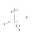
- apparatus for attachment adapter for a projectile may operate in conjunction with a projectile 100 comprising a fuze 102 and a warhead 104.
- Certain representative implementations may include, for example, adding capabilities to preexisting projectiles.
- a secondary system 200 such as a guidance kit may be installed onto a projectile 100 resulting in the ability to maneuver the projectile 100 during flight. Installation of the secondary system 200 may be accomplished via a collar 202 and a surface adapter 204 suitably configured to attach the secondary system 200 to the projectile 100.
- the projectile 100 comprises a moving system, for example to deliver a payload such as a warhead 104.
- the projectile 100 may comprise any system that is configured to travel, either with an on-board propulsion system or ballistically, such as a missile, a rocket, a bomb, or a countermeasure.
- the projectile 100 may also comprise additional elements such as a set of extendable tail fins 106 to provide stabilization during flight.
- the projectile 100 may comprise a 2.75 inch diameter folding-fin aerial rocket.
- Various aspects of the present invention may be adapted, however, to other structures, including non-projectiles, for attaching secondary structures.
- the fuze 102 acts as the detonating system to the warhead 104, which comprises the explosive or incendiary elements of the projectile 100.
- the fuze 102 may be configured in any manner to cause detonation of the warhead 104, e.g., a timed fuze, a contact detonator, a proximity fuze, an altitude fuze, or remote detonation.
- the fuze 102 may comprise an M423 or M427 point-detonating fuze that is approximately four inches in length. Other representative embodiments may comprise a fuze 102 that is between two and seven inches in length.
- the fuze 102 may be attached to the warhead 104 in any suitable manner such as by mechanical fasteners, a compression fitting, a mated thread design, or adhesively.
- the fuze 102 may further comprise notches 302 that are utilized when securing the fuze 102 to the warhead 104.
- the notches 302 may comprise flattened sections on opposite sides of the fuze 102 that allow a wrench or similar tool to screw the fuze 102 tight against the warhead 104.
- the secondary system 200 provides additional capability to a preexisting projectile 100.
- the secondary system 200 may comprise any system capable of adding capability to the projectile 100, such as movable control surfaces, guidance systems, targeting systems, and communication systems.
- an exemplary guidance kit allows the projectile 100 to be controlled during flight, increasing accuracy or reducing undesired collateral damage.
- the guidance kit may comprise a set of extendable control surface 206, a seeker 208, and a battery 210 for powering onboard systems.
- the collar 202 fits around the fuze 102 and provides an attachment point for the surface adapter 204.
- the collar 202 may comprise any system that securely attaches the surface adapter 204 to the projectile 100 and may comprise any suitable material such as metal, rubber, plastic, or composite material.
- the collar 202 may also be of any suitable length, shape, or thickness. Securing the collar 202 around the fuze 102 rather than between the fuze 102 and the warhead 104 eliminates the air gap associated with other mounting methods and preserves the integrity of the projectile 100.
- the collar 202 may comprise a single piece that is tightened around the fuze 102, such as a clamp or compression fitting, or the collar 202 may comprise multiple pieces or sections, wherein one section is mateable or interlockable with another section of the collar 202.
- the pieces may be secured to each other in any suitable manner, such as a hinge fitting, screws, bolts, clamps, grooves, and the like.
- the pieces may also be secured to each other by an external system such as the surface adapter 204.
- the collar 202 may be attachable to the surface adapter 204. Any appropriate structures or mechanisms may attach the collar 202 to the surface adapter 204, such as a removable connection or a permanent connection.
- the collar 202 may comprise mounting holes or threads along a portion of an exterior surface of the collar 202.
- the collar 202 may comprise a series of mounting holes suitably configured to receive screws adapted to affix the surface adapter 204 to the collar 202.
- the collar 202 may be configured with a series of threads suitably adapted to receive a matching series of threads on the surface adapter 204. In each of these embodiments, the collar 202 is locked around the fuze by the installation of the surface adapter 204.
- the collar 202 may comprise two metal semicircular halves, or clamshells 400.
- the dimensions and shape of the collar 202 may be selected according to the dimensions and shape of other structures, such as the fuze 102, the surface adapter 204, and/or the projectile 100.
- the collar 202 may be a half-inch to two inches in length, such as approximately one and a quarter inches in length.
- the collar 202 may have an inner radius suitably sized to fit against the fuze 102 when the two clamshells 400 are mated together.
- the collar 202 may also configured with an outer diameter less than the outer diameter of the projectile 100 body, which allows the surface adapter 204 to be fit over the collar 202 and not extend radially beyond the surface of the projectile 100.
- Each clamshell 400 may further comprise a thread pattern along a portion of an exterior surface configured to receive the surface adapter 204.
- each clamshell 400 comprises a keyway 402 that prevents the collar 202 from sliding along or spinning about the fuze 102. Motion of the collar 202 may be prevented by configuring a portion the keyway 402 to fit inside the notch 302 of the fuze 102.
- the keyway 402 may comprise any system for locking the collar 202 to the fuze 102, such as a protrusion or tab placed along the inner surface of the collar 202.
- the keyway 402 may comprise a semi-circular flattened tab positioned at the center of each clamshell 400.
- the keyway 402 may comprise multiple tabs positioned at the ends of each clamshell 400.
- the keyway 402 may comprise two quarter-circular protrusions, one positioned at each edge of the clamshell 400. The two quarter-circular protrusions may then be mated to two similar protrusions on the other clamshell 400 resulting in protrusions configured to fit inside each notch 302.
- the collar 202 may also absorb and transfer maneuver loads from the surface adapter 204 to the warhead 104 section of the projectile 100.
- the collar 202 may engage the projectile 100, such as via shoulders on the outer surface of the collar 202 where it engages the warhead 104.
- the shoulders may comprise any system for transferring loads from the collar 202 to the warhead 104.
- the shoulders may comprise an angled surface 404 on one end of the clamshell 400.
- the shoulders may comprise a flexible element, such as a rubberized tab.
- the surface adapter 204 secures the secondary system 200 to the collar 202.
- the surface adapter 204 may comprise any system for attachment, such as a one-piece skin configured to slide over and substantially cover the collar 202 and fuze 102, or the surface adapter 204 may comprise multiple pieces configured to be positioned around the collar 202 and the fuze 102 and then connected together, such as by connectors or bands.
- the surface adapter 204 may also comprise any suitable material, such a metal, composite, fiberglass, or other material capable of withstanding launch and aerodynamic related forces associated with airstream velocity over the surface of the projectile 100.
- the surface adapter 204 may comprise the same material as the body of the projectile 100.
- the surface adapter 204 may be attached to the collar 202 by any suitable structure and/or method.
- the surface adapter 204 may be affixed to the collar 202 via screws 502.
- the surface adapter 204 may slide over the fuze 102 and collar 202 and then screw onto the collar 202 via threads.
- the surface adapter 204 may further comprise a mechanism for securing the secondary system 200 to the surface adapter 204.
- the surface adapter 204 may comprise threads 306 that engage a matching set of threads on the secondary system 200.
- the surface adapter 204 may further be configured to seal the collar 202 and the fuze 102 from the outside environment.
- the surface adapter 204 may further comprise an o-ring 304 to seal the interior volume around the fuze 102.
- the o-ring 304 may further be adapted to provide a tight fitting between the surface adapter 204 and the warhead 104, assist in transferring loads from the secondary system 200 to the projectile 100, and prevent unwanted movement between the surface adapter 204 and the projectile 100.
- the collar 202 and surface adapter 204 may further be configured to be removed after installation. Impermanent installation may permit an unguided projectile 100 to be retrofitted with a secondary system 200 or a secondary system 200 to be removed from a previously retrofitted projectile 100 without causing operational limitations or damage to the projectile 100. Impermanent installation may also provide for use of a single secondary system 200 with various projectiles 100, depending on the specific need, application, or situation. Installation or removal of the collar 202 and surface adapter 204 may also be performed in the field without requiring special tooling. The adaptable installation method also allows for the secondary system 200 to be installed on new projectiles and removed by field personnel if the additional capability is not required.
- the secondary system 200 may be affixed to the projectile 100, such as a standard unguided projectile, via the collar 202 and the surface adapter 204.
- the collar 202 may be fit around the fuze 102 of the projectile 100.
- the keyway 402 of each clamshell 400 may be aligned with the notches 302 on the outer surface of the fuze 102.
- the surface adapter 204 is secured around the collar 202, locking it around the fuze 102.
- the surface adapter 204 may be secured to the collar 202 by any suitable method.
- the surface adapter is slid over the collar 202 and secured by screws through the surface adapter 204 and into the collar 202.
- a secondary system 200 such as a guidance kit, may be affixed to the surface adapter 204 by any suitable method.
- the projectile 100 may be placed into operation.
- the projectile 100 may be placed into a launcher mounted to an aircraft such as a helicopter.
- the guidance kit may be communicatively linked to the targeting systems inside the helicopter. In this manner, the guidance kit may be used to more accurately direct the projectile 100 towards an intended target after launch.
Claims (7)
- Sprengkapselbaugruppe eines Projektils (100), umfassend eine Sprengkapsel (102) und einen Befestigungsadapter, der einen Kragen (202) enthält;
dadurch gekennzeichnet, dass die Sprengkapsel (102) teilweise innerhalb des Kragens (202) angeordnet ist, dass der Kragen (202) mechanisch an eine Kerbe (302) in der Sprengkapsel gekoppelt ist und dass der Kragen (202) zwei Zweischalengreifer-Hälften (400) umfasst. - Sprengkapselbaugruppe nach Anspruch 1, wobei der Kragen (202) weiterhin eine Nut (402) umfasst, die konfiguriert ist zum Koppeln an den Kragen (202) an der Sprengkapselbaugruppe.
- Sprengkapselbaugruppe nach Anspruch 1 oder 2, wobei der Kragen (202) entfernbar an der Sprengkapselbaugruppe angebracht werden kann.
- Sprengkapselbaugruppe nach einem der Ansprüche 1 bis 3, weiterhin umfassend einen Oberflächenadapter (204), wobei der Oberflächenadapter (204) konfiguriert ist zum:Anbringen an dem und im Wesentlichen Bedecken des Kragens (202) und Aufnehmen eines sekundären Systems (200).
- Sprengkapselbaugruppe nach Anspruch 4, wobei der Oberflächenadapter entfernbar an dem Kragen (202), der Sprengkapselbaugruppe und/oder dem Projektil angebracht ist.
- Sprengkapselbaugruppe nach Anspruch 4 oder 5, wobei der Oberflächenadapter eine einteilige Haut umfasst, die konfiguriert ist zum Gleiten über den Kragen (202).
- Sprengkapselbaugruppe nach einem der Ansprüche 4 bis 6, wobei eine äußere Oberfläche des Oberflächenadapters einen Radius besitzt, der ungefähr gleich dem Radius des Projektils ist.
Applications Claiming Priority (2)
| Application Number | Priority Date | Filing Date | Title |
|---|---|---|---|
| US94300107P | 2007-06-08 | 2007-06-08 | |
| PCT/US2008/066195 WO2009020697A2 (en) | 2007-06-08 | 2008-06-06 | Methods and apparatus for attachment adapter for a projectile |
Publications (3)
| Publication Number | Publication Date |
|---|---|
| EP2158443A2 EP2158443A2 (de) | 2010-03-03 |
| EP2158443A4 EP2158443A4 (de) | 2013-03-27 |
| EP2158443B1 true EP2158443B1 (de) | 2014-11-12 |
Family
ID=40341961
Family Applications (1)
| Application Number | Title | Priority Date | Filing Date |
|---|---|---|---|
| EP08826896.6A Active EP2158443B1 (de) | 2007-06-08 | 2008-06-06 | Verfahren und vorrichtung für einen befestigungsadapter für ein projektil |
Country Status (3)
| Country | Link |
|---|---|
| US (1) | US8069790B1 (de) |
| EP (1) | EP2158443B1 (de) |
| WO (1) | WO2009020697A2 (de) |
Families Citing this family (5)
| Publication number | Priority date | Publication date | Assignee | Title |
|---|---|---|---|---|
| US8291827B2 (en) * | 2009-09-28 | 2012-10-23 | Raytheon Company | Rocket guidance adapter |
| US9810513B2 (en) * | 2014-08-04 | 2017-11-07 | Raytheon Company | Munition modification kit and method of modifying munition |
| US10928169B2 (en) | 2019-02-07 | 2021-02-23 | Bae Systems Rokar International Ltd. | Seal for a projectile guiding kit |
| IL264739B (en) * | 2019-02-07 | 2022-09-01 | Elbit Systems Rokar Ltd | A seal for the protection of the arming guide head and a method for its installation and operation |
| CN115355768B (zh) * | 2022-05-24 | 2023-12-19 | 湖北航天技术研究院总体设计所 | 带辅助支撑的火箭适配器结构及火箭整流罩分离方法 |
Family Cites Families (25)
| Publication number | Priority date | Publication date | Assignee | Title |
|---|---|---|---|---|
| US918560A (en) * | 1908-08-22 | 1909-04-20 | Leon Duvignau De Lanneau | Cap for projectiles. |
| US1531716A (en) * | 1924-02-05 | 1925-03-31 | Remondy Leon Emile | Apparatus for transmitting the firing to the charge in projectiles of elongated shape |
| US3054646A (en) * | 1959-09-28 | 1962-09-18 | Bettis Rubber Company | Split collar |
| US3670656A (en) * | 1965-01-26 | 1972-06-20 | Us Navy | Fuze arming device |
| US3374632A (en) * | 1965-11-23 | 1968-03-26 | Navy Usa | Liquid propellant rocket |
| US3440963A (en) * | 1967-08-15 | 1969-04-29 | Peter L De Luca | Dummy warhead for rocket,missile or the like |
| US4500051A (en) * | 1972-10-06 | 1985-02-19 | Texas Instruments Incorporated | Gyro stabilized optics with fixed detector |
| US4205608A (en) * | 1978-07-24 | 1980-06-03 | The United States Of America As Represented By The Secretary Of The Army | Fuze well stress attenuator for projectiles |
| US4326463A (en) | 1980-05-27 | 1982-04-27 | The United States Of America As Represented By The Secretary Of The Army | Dye marker assembly for rocket practice round |
| US4638737A (en) * | 1985-06-28 | 1987-01-27 | The United States Of America As Represented By The Secretary Of The Army | Multi-warhead, anti-armor missile |
| DE3639201A1 (de) * | 1986-11-15 | 1988-05-19 | Junghans Gmbh Geb | Friktionseinrichtung fuer den tempiervorgang an geschosszuendern |
| US5226678A (en) * | 1987-03-31 | 1993-07-13 | Petranto Joseph J | Split gland |
| US4756226A (en) * | 1987-11-09 | 1988-07-12 | General Dynamics, Pomona Division | Missile support structure for a launch tube |
| US5014591A (en) * | 1990-01-02 | 1991-05-14 | Raytheon Company | Multiple encoder fuze |
| US5152556A (en) * | 1990-12-24 | 1992-10-06 | Kaiser Aerospace And Electronics Corporation | High temperature tubing joint with threaded, split collar |
| US5164539A (en) * | 1991-10-31 | 1992-11-17 | K. W. Thompson Tool Company, Inc. | Projectile carrier |
| US5263418A (en) * | 1992-01-24 | 1993-11-23 | Olin Corporation | Hollow point sabot bullet |
| US5245927A (en) * | 1992-04-28 | 1993-09-21 | Northrop Corporation | Dual-tandem unmanned air vehicle system |
| US5280706A (en) * | 1992-06-25 | 1994-01-25 | Thiokol Corporation | Composite/metal hybrid rocket motor case and methods for manufacturing |
| US5358283A (en) * | 1993-06-21 | 1994-10-25 | Silva Lawrence S | Split connector pipe joining device and method |
| US6408762B1 (en) * | 1997-12-11 | 2002-06-25 | Lockheed Martin Corporation | Clamp assembly for shrouded aerial bomb |
| US6374744B1 (en) * | 2000-05-25 | 2002-04-23 | Lockheed Martin Corporation | Shrouded bomb |
| WO2002029270A1 (de) * | 2000-09-29 | 2002-04-11 | Federal-Mogul Wiesbaden Gmbh & Co. Kg | Bundlagerhalbschale und bundlager mit zentriervorrichtung sowie dazugehörige anlaufscheibe |
| US7261042B1 (en) * | 2004-07-08 | 2007-08-28 | Lockheed Martins Corporation | Insensitive munition design for shrouded penetrators |
| FR2910613B1 (fr) * | 2006-12-21 | 2009-10-02 | Ateliers Mecaniques De Pont Su | Projectile guide muni d'un manchon pour le montage d'un systeme de guidage |
-
2008
- 2008-06-06 EP EP08826896.6A patent/EP2158443B1/de active Active
- 2008-06-06 WO PCT/US2008/066195 patent/WO2009020697A2/en active Application Filing
- 2008-06-09 US US12/135,371 patent/US8069790B1/en active Active
Also Published As
| Publication number | Publication date |
|---|---|
| WO2009020697A3 (en) | 2009-04-02 |
| EP2158443A4 (de) | 2013-03-27 |
| WO2009020697A2 (en) | 2009-02-12 |
| US8069790B1 (en) | 2011-12-06 |
| EP2158443A2 (de) | 2010-03-03 |
Similar Documents
| Publication | Publication Date | Title |
|---|---|---|
| US5806791A (en) | Missile jet vane control system and method | |
| EP1685362B1 (de) | Geschoss mit mehreren nasenkegeln | |
| DE19740888C2 (de) | Verfahren zum autonomen Lenken eines drallstabilisierten Artilleriegeschosses und autonom gelenktes Artilleriegeschoß zur Durchführung des Verfahrens | |
| US8916810B2 (en) | Steerable spin-stabilized projectile | |
| EP2158443B1 (de) | Verfahren und vorrichtung für einen befestigungsadapter für ein projektil | |
| US20170299355A1 (en) | Artillery projectile with a piloted phase | |
| US20120181376A1 (en) | Munition and guidance navigation and control unit | |
| CN114829868B (zh) | 弹药前锥 | |
| US9857154B2 (en) | Steerable munitions projectile | |
| EP2276998B1 (de) | Vorrichtung zur arretierung und lösung einer luftbremse | |
| US8302524B2 (en) | Aerodynamic rotating launcher | |
| US20050145750A1 (en) | Flying body for firing from a tube with over-calibre stabilisers | |
| EP2539666B1 (de) | Mit erweiterbaren flügeln und einer führungsvorrichtung ausgerüstete bombe | |
| US9546853B2 (en) | Air vehicle with control system mechanical coupler | |
| EP1328768B1 (de) | Verfahren und vorrichtung für die verlängerung der flugbahnstrecke eines flügelstabilisierten artilleriegeschosses | |
| EP2483629B1 (de) | Raketensteuerungsadapter |
Legal Events
| Date | Code | Title | Description |
|---|---|---|---|
| PUAI | Public reference made under article 153(3) epc to a published international application that has entered the european phase |
Free format text: ORIGINAL CODE: 0009012 |
|
| 17P | Request for examination filed |
Effective date: 20100105 |
|
| AK | Designated contracting states |
Kind code of ref document: A2 Designated state(s): AT BE BG CH CY CZ DE DK EE ES FI FR GB GR HR HU IE IS IT LI LT LU LV MC MT NL NO PL PT RO SE SI SK TR |
|
| AX | Request for extension of the european patent |
Extension state: AL BA MK RS |
|
| RIN1 | Information on inventor provided before grant (corrected) |
Inventor name: MELKERS, EDGAR, R. |
|
| DAX | Request for extension of the european patent (deleted) | ||
| REG | Reference to a national code |
Ref country code: DE Ref legal event code: R079 Ref document number: 602008035353 Country of ref document: DE Free format text: PREVIOUS MAIN CLASS: F42D0001055000 Ipc: F42B0015010000 |
|
| A4 | Supplementary search report drawn up and despatched |
Effective date: 20130225 |
|
| RIC1 | Information provided on ipc code assigned before grant |
Ipc: F42B 15/36 20060101ALI20130219BHEP Ipc: F42B 15/01 20060101AFI20130219BHEP |
|
| GRAP | Despatch of communication of intention to grant a patent |
Free format text: ORIGINAL CODE: EPIDOSNIGR1 |
|
| INTG | Intention to grant announced |
Effective date: 20140527 |
|
| GRAS | Grant fee paid |
Free format text: ORIGINAL CODE: EPIDOSNIGR3 |
|
| GRAA | (expected) grant |
Free format text: ORIGINAL CODE: 0009210 |
|
| AK | Designated contracting states |
Kind code of ref document: B1 Designated state(s): AT BE BG CH CY CZ DE DK EE ES FI FR GB GR HR HU IE IS IT LI LT LU LV MC MT NL NO PL PT RO SE SI SK TR |
|
| REG | Reference to a national code |
Ref country code: GB Ref legal event code: FG4D |
|
| REG | Reference to a national code |
Ref country code: CH Ref legal event code: EP |
|
| REG | Reference to a national code |
Ref country code: AT Ref legal event code: REF Ref document number: 696022 Country of ref document: AT Kind code of ref document: T Effective date: 20141115 |
|
| REG | Reference to a national code |
Ref country code: IE Ref legal event code: FG4D |
|
| REG | Reference to a national code |
Ref country code: DE Ref legal event code: R096 Ref document number: 602008035353 Country of ref document: DE Effective date: 20141224 |
|
| REG | Reference to a national code |
Ref country code: NL Ref legal event code: VDEP Effective date: 20141112 |
|
| REG | Reference to a national code |
Ref country code: AT Ref legal event code: MK05 Ref document number: 696022 Country of ref document: AT Kind code of ref document: T Effective date: 20141112 |
|
| PG25 | Lapsed in a contracting state [announced via postgrant information from national office to epo] |
Ref country code: FI Free format text: LAPSE BECAUSE OF FAILURE TO SUBMIT A TRANSLATION OF THE DESCRIPTION OR TO PAY THE FEE WITHIN THE PRESCRIBED TIME-LIMIT Effective date: 20141112 Ref country code: LT Free format text: LAPSE BECAUSE OF FAILURE TO SUBMIT A TRANSLATION OF THE DESCRIPTION OR TO PAY THE FEE WITHIN THE PRESCRIBED TIME-LIMIT Effective date: 20141112 Ref country code: PT Free format text: LAPSE BECAUSE OF FAILURE TO SUBMIT A TRANSLATION OF THE DESCRIPTION OR TO PAY THE FEE WITHIN THE PRESCRIBED TIME-LIMIT Effective date: 20150312 Ref country code: NL Free format text: LAPSE BECAUSE OF FAILURE TO SUBMIT A TRANSLATION OF THE DESCRIPTION OR TO PAY THE FEE WITHIN THE PRESCRIBED TIME-LIMIT Effective date: 20141112 Ref country code: ES Free format text: LAPSE BECAUSE OF FAILURE TO SUBMIT A TRANSLATION OF THE DESCRIPTION OR TO PAY THE FEE WITHIN THE PRESCRIBED TIME-LIMIT Effective date: 20141112 Ref country code: IS Free format text: LAPSE BECAUSE OF FAILURE TO SUBMIT A TRANSLATION OF THE DESCRIPTION OR TO PAY THE FEE WITHIN THE PRESCRIBED TIME-LIMIT Effective date: 20150312 Ref country code: NO Free format text: LAPSE BECAUSE OF FAILURE TO SUBMIT A TRANSLATION OF THE DESCRIPTION OR TO PAY THE FEE WITHIN THE PRESCRIBED TIME-LIMIT Effective date: 20150212 |
|
| PG25 | Lapsed in a contracting state [announced via postgrant information from national office to epo] |
Ref country code: HR Free format text: LAPSE BECAUSE OF FAILURE TO SUBMIT A TRANSLATION OF THE DESCRIPTION OR TO PAY THE FEE WITHIN THE PRESCRIBED TIME-LIMIT Effective date: 20141112 Ref country code: GR Free format text: LAPSE BECAUSE OF FAILURE TO SUBMIT A TRANSLATION OF THE DESCRIPTION OR TO PAY THE FEE WITHIN THE PRESCRIBED TIME-LIMIT Effective date: 20150213 Ref country code: PL Free format text: LAPSE BECAUSE OF FAILURE TO SUBMIT A TRANSLATION OF THE DESCRIPTION OR TO PAY THE FEE WITHIN THE PRESCRIBED TIME-LIMIT Effective date: 20141112 Ref country code: LV Free format text: LAPSE BECAUSE OF FAILURE TO SUBMIT A TRANSLATION OF THE DESCRIPTION OR TO PAY THE FEE WITHIN THE PRESCRIBED TIME-LIMIT Effective date: 20141112 Ref country code: AT Free format text: LAPSE BECAUSE OF FAILURE TO SUBMIT A TRANSLATION OF THE DESCRIPTION OR TO PAY THE FEE WITHIN THE PRESCRIBED TIME-LIMIT Effective date: 20141112 Ref country code: CY Free format text: LAPSE BECAUSE OF FAILURE TO SUBMIT A TRANSLATION OF THE DESCRIPTION OR TO PAY THE FEE WITHIN THE PRESCRIBED TIME-LIMIT Effective date: 20141112 Ref country code: SE Free format text: LAPSE BECAUSE OF FAILURE TO SUBMIT A TRANSLATION OF THE DESCRIPTION OR TO PAY THE FEE WITHIN THE PRESCRIBED TIME-LIMIT Effective date: 20141112 |
|
| PG25 | Lapsed in a contracting state [announced via postgrant information from national office to epo] |
Ref country code: RO Free format text: LAPSE BECAUSE OF FAILURE TO SUBMIT A TRANSLATION OF THE DESCRIPTION OR TO PAY THE FEE WITHIN THE PRESCRIBED TIME-LIMIT Effective date: 20141112 Ref country code: SK Free format text: LAPSE BECAUSE OF FAILURE TO SUBMIT A TRANSLATION OF THE DESCRIPTION OR TO PAY THE FEE WITHIN THE PRESCRIBED TIME-LIMIT Effective date: 20141112 Ref country code: EE Free format text: LAPSE BECAUSE OF FAILURE TO SUBMIT A TRANSLATION OF THE DESCRIPTION OR TO PAY THE FEE WITHIN THE PRESCRIBED TIME-LIMIT Effective date: 20141112 Ref country code: DK Free format text: LAPSE BECAUSE OF FAILURE TO SUBMIT A TRANSLATION OF THE DESCRIPTION OR TO PAY THE FEE WITHIN THE PRESCRIBED TIME-LIMIT Effective date: 20141112 Ref country code: CZ Free format text: LAPSE BECAUSE OF FAILURE TO SUBMIT A TRANSLATION OF THE DESCRIPTION OR TO PAY THE FEE WITHIN THE PRESCRIBED TIME-LIMIT Effective date: 20141112 |
|
| REG | Reference to a national code |
Ref country code: DE Ref legal event code: R097 Ref document number: 602008035353 Country of ref document: DE |
|
| PLBE | No opposition filed within time limit |
Free format text: ORIGINAL CODE: 0009261 |
|
| STAA | Information on the status of an ep patent application or granted ep patent |
Free format text: STATUS: NO OPPOSITION FILED WITHIN TIME LIMIT |
|
| 26N | No opposition filed |
Effective date: 20150813 |
|
| PG25 | Lapsed in a contracting state [announced via postgrant information from national office to epo] |
Ref country code: IT Free format text: LAPSE BECAUSE OF FAILURE TO SUBMIT A TRANSLATION OF THE DESCRIPTION OR TO PAY THE FEE WITHIN THE PRESCRIBED TIME-LIMIT Effective date: 20141112 |
|
| PG25 | Lapsed in a contracting state [announced via postgrant information from national office to epo] |
Ref country code: MC Free format text: LAPSE BECAUSE OF FAILURE TO SUBMIT A TRANSLATION OF THE DESCRIPTION OR TO PAY THE FEE WITHIN THE PRESCRIBED TIME-LIMIT Effective date: 20141112 |
|
| REG | Reference to a national code |
Ref country code: CH Ref legal event code: PL |
|
| PG25 | Lapsed in a contracting state [announced via postgrant information from national office to epo] |
Ref country code: SI Free format text: LAPSE BECAUSE OF FAILURE TO SUBMIT A TRANSLATION OF THE DESCRIPTION OR TO PAY THE FEE WITHIN THE PRESCRIBED TIME-LIMIT Effective date: 20141112 Ref country code: LU Free format text: LAPSE BECAUSE OF FAILURE TO SUBMIT A TRANSLATION OF THE DESCRIPTION OR TO PAY THE FEE WITHIN THE PRESCRIBED TIME-LIMIT Effective date: 20150606 |
|
| REG | Reference to a national code |
Ref country code: IE Ref legal event code: MM4A |
|
| PG25 | Lapsed in a contracting state [announced via postgrant information from national office to epo] |
Ref country code: CH Free format text: LAPSE BECAUSE OF NON-PAYMENT OF DUE FEES Effective date: 20150630 Ref country code: LI Free format text: LAPSE BECAUSE OF NON-PAYMENT OF DUE FEES Effective date: 20150630 Ref country code: IE Free format text: LAPSE BECAUSE OF NON-PAYMENT OF DUE FEES Effective date: 20150606 |
|
| REG | Reference to a national code |
Ref country code: FR Ref legal event code: PLFP Year of fee payment: 9 |
|
| PG25 | Lapsed in a contracting state [announced via postgrant information from national office to epo] |
Ref country code: MT Free format text: LAPSE BECAUSE OF FAILURE TO SUBMIT A TRANSLATION OF THE DESCRIPTION OR TO PAY THE FEE WITHIN THE PRESCRIBED TIME-LIMIT Effective date: 20141112 |
|
| REG | Reference to a national code |
Ref country code: FR Ref legal event code: PLFP Year of fee payment: 10 |
|
| PG25 | Lapsed in a contracting state [announced via postgrant information from national office to epo] |
Ref country code: HU Free format text: LAPSE BECAUSE OF FAILURE TO SUBMIT A TRANSLATION OF THE DESCRIPTION OR TO PAY THE FEE WITHIN THE PRESCRIBED TIME-LIMIT; INVALID AB INITIO Effective date: 20080606 Ref country code: BG Free format text: LAPSE BECAUSE OF FAILURE TO SUBMIT A TRANSLATION OF THE DESCRIPTION OR TO PAY THE FEE WITHIN THE PRESCRIBED TIME-LIMIT Effective date: 20141112 |
|
| PG25 | Lapsed in a contracting state [announced via postgrant information from national office to epo] |
Ref country code: TR Free format text: LAPSE BECAUSE OF FAILURE TO SUBMIT A TRANSLATION OF THE DESCRIPTION OR TO PAY THE FEE WITHIN THE PRESCRIBED TIME-LIMIT Effective date: 20141112 |
|
| PG25 | Lapsed in a contracting state [announced via postgrant information from national office to epo] |
Ref country code: BE Free format text: LAPSE BECAUSE OF FAILURE TO SUBMIT A TRANSLATION OF THE DESCRIPTION OR TO PAY THE FEE WITHIN THE PRESCRIBED TIME-LIMIT Effective date: 20141112 |
|
| REG | Reference to a national code |
Ref country code: FR Ref legal event code: PLFP Year of fee payment: 11 |
|
| P01 | Opt-out of the competence of the unified patent court (upc) registered |
Effective date: 20230530 |
|
| PGFP | Annual fee paid to national office [announced via postgrant information from national office to epo] |
Ref country code: FR Payment date: 20230524 Year of fee payment: 16 Ref country code: DE Payment date: 20230523 Year of fee payment: 16 |
|
| PGFP | Annual fee paid to national office [announced via postgrant information from national office to epo] |
Ref country code: GB Payment date: 20230523 Year of fee payment: 16 |