EP2158115B1 - Duct provided with a device for absorption of pressure pulses - Google Patents
Duct provided with a device for absorption of pressure pulses Download PDFInfo
- Publication number
- EP2158115B1 EP2158115B1 EP08762924A EP08762924A EP2158115B1 EP 2158115 B1 EP2158115 B1 EP 2158115B1 EP 08762924 A EP08762924 A EP 08762924A EP 08762924 A EP08762924 A EP 08762924A EP 2158115 B1 EP2158115 B1 EP 2158115B1
- Authority
- EP
- European Patent Office
- Prior art keywords
- duct
- chamber
- inertial element
- pipe
- fluid
- Prior art date
- Legal status (The legal status is an assumption and is not a legal conclusion. Google has not performed a legal analysis and makes no representation as to the accuracy of the status listed.)
- Not-in-force
Links
Images



Classifications
-
- B—PERFORMING OPERATIONS; TRANSPORTING
- B62—LAND VEHICLES FOR TRAVELLING OTHERWISE THAN ON RAILS
- B62D—MOTOR VEHICLES; TRAILERS
- B62D5/00—Power-assisted or power-driven steering
- B62D5/06—Power-assisted or power-driven steering fluid, i.e. using a pressurised fluid for most or all the force required for steering a vehicle
- B62D5/062—Details, component parts
-
- F—MECHANICAL ENGINEERING; LIGHTING; HEATING; WEAPONS; BLASTING
- F15—FLUID-PRESSURE ACTUATORS; HYDRAULICS OR PNEUMATICS IN GENERAL
- F15B—SYSTEMS ACTING BY MEANS OF FLUIDS IN GENERAL; FLUID-PRESSURE ACTUATORS, e.g. SERVOMOTORS; DETAILS OF FLUID-PRESSURE SYSTEMS, NOT OTHERWISE PROVIDED FOR
- F15B21/00—Common features of fluid actuator systems; Fluid-pressure actuator systems or details thereof, not covered by any other group of this subclass
- F15B21/008—Reduction of noise or vibration
-
- F—MECHANICAL ENGINEERING; LIGHTING; HEATING; WEAPONS; BLASTING
- F16—ENGINEERING ELEMENTS AND UNITS; GENERAL MEASURES FOR PRODUCING AND MAINTAINING EFFECTIVE FUNCTIONING OF MACHINES OR INSTALLATIONS; THERMAL INSULATION IN GENERAL
- F16L—PIPES; JOINTS OR FITTINGS FOR PIPES; SUPPORTS FOR PIPES, CABLES OR PROTECTIVE TUBING; MEANS FOR THERMAL INSULATION IN GENERAL
- F16L55/00—Devices or appurtenances for use in, or in connection with, pipes or pipe systems
- F16L55/04—Devices damping pulsations or vibrations in fluids
- F16L55/041—Devices damping pulsations or vibrations in fluids specially adapted for preventing vibrations
Definitions
- the present invention relates to a duct which is provided with a device for absorption of pressure pulses, preferably for use in a hydraulic steering system of a motor vehicle.
- a hydraulic steering system generally comprises a supply pump, a steering actuator which is connected to the front wheels, and a hydraulic line in order to connect the pump to the steering actuator.
- the hydraulic line comprises a high-pressure pipe in order to connect the pump to the actuator, and a low-pressure discharge duct for recuperation of the work fluid.
- the pumps which supply hydraulic steering systems are generally vane pumps, and generate a flow with a rate characterised by harmonic irregularities which are equal to the number of the vanes of the pump, and with a basic frequency defined by the number of revolutions of the pump.
- These irregularities of flow generate pressure pulses in the hydraulic steering system, and consequently undesirable noise.
- the pressure pulses which are generated by the irregularities of flow are characterised by a high frequency in a band between 100Hz and 500Hz; in particular, the minimum value of this frequency band (fmin) which is typical of a hydraulic steering system can be calculated theoretically as the ratio of the minimum number of revolutions of the engine (RPMidle) multiplied by the ratio of transmission between the pump and engine (RT) and the number of vanes (Nvanes).
- hydraulic steering systems are not subjected to an external forcing agent with a frequency lower than that calculated by means of the formula (1), and therefore lower than 100-120Hz.
- Patent application DE 10 2004 045 100 describes two embodiments of a spring damper for a breaking circuit that is not provided with a pump.
- a piston is housed in a chamber and is kept in an equilibrium position by means of two opposing springs.
- the chamber is connected in parallel to a main adduction line by means of a first and a second conduit set at opposite sides with respect to the piston.
- a portion of the energy carried by a pressure peak due e.g. to an abrupt actuation of the pedal is converted in elastic potential energy and this causes a reduction of the oscillations.
- a throttling is set along the adduction line to dampen the pulsations.
- the chamber housing the piston and the two springs is connected to the adduction line by means of a single connection. Furthermore, the piston defines a through hole to allow the fluid flow when the piston is moving.
- the springs function as elastic potential energy accumulators and this requires that a substantial quantity of fluid flows through the connections.
- the accumulated energy is returned in the system with a delay with respect to the initial peak and this attenuates the pulsations.
- the object of the present invention is to produce a duct which is provided with a device to absorb the pressure pulses, and is free from the above-described disadvantages.
- the object of the present invention is obtained by means of a duct provided with a device for absorption of the pressure pulses, as defined in claim 1.
- 1 indicates as a whole a hydraulic steering system comprising a hydraulic pump 2, which, by means of suction piping 3, is connected to a work fluid (oil) tank 4.
- 5 indicates as a whole high-pressure supply piping, which connects the delivery of the pump 2 to a steering box or unit 6, of a type which in itself is known.
- a first low-pressure return duct 7 for the work fluid which in the example illustrated is produced with alternately flexible and rigid sections, connects the steering box or unit 6 to a cooling coil-type heat exchanger 8, for cooling of this fluid.
- the outlet of the exchanger 8 is connected to the tank 4 by means of a second return duct, indicated as 9, and also formed by pieces or sections of flexible and rigid piping.
- the high-pressure piping 5 and/or at least one of the low-pressure ducts 7, 9 comprise a pipe 10 and an absorption device 11, which is connected in parallel to the pipe 10 ( figure 2 ).
- the absorption device 11 defines an elongate cylindrical chamber 12 and an inertial element 13, for example a sphere, which is mobile in the chamber 12, and a pair of springs 14, 15 which are fitted on opposite sides in relation to the inertial element 13 inside the chamber 12.
- the springs 14, 15 co-operate with the inertial element 13 in order to define the position of the latter in both static and dynamic conditions, as will be described in greater detail hereinafter.
- the chamber 12 is connected to the pipe 10 by means of a pair of connections 16, 17 which define respective narrowed parts R1, R2 disposed on opposite sides in relation to the inertial element 13 at a distance L along the pipe 10.
- the narrowed parts R1, R2 have respective diameters which are smaller than that of the pipe 10, such that the connections 16, 17 substantially do not have a flow of fluid passing through them.
- the inertial element 13 divides the chamber 12 into two compartments 12a, 12b which have a volume which varies depending on the position of the inertial element 13, and are connected to the pipe 10 by means of the connection 16 and the connection 17 respectively.
- the compartments 12a, 12b communicate with one another in a fluid manner inside the chamber 12, by means of a passage P.
- the passage P disconnects the pressure of the compartment 12a from that of the compartment 12b, and is provided, for example, by means of an annular channel defined between the inertial element 13 and a lateral wall 18 of the chamber 12.
- the absorption device 11 comprises the two connections 16, 17 which are connected to respective apertures 19, 20 in the pipe 10 and a rigid, substantially tubular intermediate element 22 which is interposed between the connections 16, 17.
- connection 16 there pass respective ducts 23 and 24 which have a development in the shape of an "L", and define the narrowed parts R1, R2 respectively.
- the duct 23 of the connection 16 has two sections 23a and 23b which are at right-angles to one another, and communicate: the section 23a is connected to the pipe 10 and the section 23b extends parallel to this pipe, and opens inside the intermediate tubular element 22.
- the duct 24 of the terminal element 21 has two sections 24a and 24b, of which the former communicates with the pipe 10 at a distance L from the aperture 12 in the piping 5, and the latter opens inside the intermediate tubular element 22.
- connections 16, 17 have respective facing protuberances 16a and 17a, which are engaged in the corresponding ends of the intermediate tubular element 22, with interposition of respective "O"-ring seals.
- the inertial element 13 comprising a piston 26, which in the example illustrated is substantially cylindrical. From the opposite sides of the piston 26 there extend two axially aligned rods 27 and 28.
- the piston 26 is fitted such as to be mobile in the chamber 12, and defines the passage P in order to permit the leakage of the fluid between the compartments 12a, 12b.
- This leakage can be made possible by the effect of radial play between the piston 26 and the lateral wall 18 of the chamber 12, and/or by other arrangements such as holes or notches in its periphery.
- the springs 14, 15 are disposed on opposite sides in relation to the piston 26, respectively around the rod 27 and the rod 28.
- Figure 4 illustrates the diagram of a high- or low-pressure duct 30 according to a further embodiment of the present invention, in which the components which are functionally identical to the components of the duct 1 are indicated by the same reference numbers as those used in the description of the high-pressure piping 5.
- the duct 30 comprises the pipe 10 and an absorption device 31 which defines the chamber 12, and comprises the connections 16, 17, a cylindrical drawer 32 which slides in the chamber 12, and the springs 14, 15.
- the drawer 32 defines an axial through hole which constitutes the passage P and permits the absorption action by means of the transfer of work fluid between the compartment 12a and the compartment 12b inside the chamber 12.
- the pipe 10 and the absorption device 11, 31 are fitted along the high-pressure piping 5 in order to absorb efficiently the pressure pulses generated by the irregularity of rotation of the shaft with bends, and/or along at least one of the low-pressure ducts 7, 9, in order to absorb the low-frequency pulses caused for example by the hydraulic-mechanical resonance of the suspension system.
- the pressure pulse of the pipe 10 is transmitted inside the compartments 12a, 12b by the respective connections 16, 17, and causes forced oscillation of the inertial element 13.
- the inertial element 13 is subjected to the action of the relative pressure derived from the difference in the absolute pressures which are present respectively in the compartments 12a, 12b.
- the absorption device 11, 31 thus defines a dynamic absorber wherein the mass is constituted by the inertial element 13, and the stiffness is defined by the pair of springs 14, 15.
- the ratio between the stiffness of the springs 14, 15 and the mass of the inertial element 13 can be such as to obtain a resonant system which is extremely efficient in dissipating the energy of the pulses which are derived from the pipe 10, and have frequencies contained in a low-frequency interval which depends on the aforementioned ratio.
- Narrowed parts R1, R2 avoid that a considerable quantity of fluid flows in device 11 and allow, at least theoretically, that only a pressure signal propagates in chamber 12. It is therefore avoided that an excessive amount of fluid is accumulated in chamber 12.
- the passage P defines localised hydraulic resistance by means of which the work fluid is blown by, in order to absorb the oscillation of the inertial element 13.
- the effect of the absorption device 11, 31 in parallel with the pipe 10 can be determined experimentally, or it can be investigated analytically on the basis of a suitable mathematical model.
- the two graphs in figure 5 compare (when there is variation of the frequency f recorded on the x-axis) developments of the amplitude A and of the phase f of the vibration for a duct without the device 11, 31 (curves in a thin line) and for a duct provided with the device 11, 31 according to the invention (curves in a thicker line).
- the solution according to the invention substantially makes it possible to eliminate the low-frequency resonance peaks, whilst maintaining unaltered the layout of the high-pressure supply piping. This therefore provides an optimum compromise between compactness and strength.
- absorption device 11, 31 is reactive, it is extremely efficient in reducing the noise caused by pulses, and can easily be designed to attenuate the low-frequency pressure pulses.
- the absorption device 11, 31 is compact and fitted in parallel with the pipe 10, inside which the conventional quarter-wave silencer pipes can be fitted.
- the absorption device 11, 31 does not have undesirable dissipative effects, and it does not affect the response time of the power steering system.
- the chamber 12 is defined by a flexible pipe comprising a layer of polymer material, for example by a piece of pipe for the high-pressure branch of a hydraulic steering system.
Landscapes
- Engineering & Computer Science (AREA)
- Mechanical Engineering (AREA)
- General Engineering & Computer Science (AREA)
- Chemical & Material Sciences (AREA)
- Fluid Mechanics (AREA)
- Transportation (AREA)
- Analytical Chemistry (AREA)
- Physics & Mathematics (AREA)
- Combustion & Propulsion (AREA)
- Pipe Accessories (AREA)
- Fluid-Damping Devices (AREA)
- Fluid-Pressure Circuits (AREA)
- Paper (AREA)
- Measuring Fluid Pressure (AREA)
- Measuring Pulse, Heart Rate, Blood Pressure Or Blood Flow (AREA)
- Power Steering Mechanism (AREA)
Abstract
Description
- The present invention relates to a duct which is provided with a device for absorption of pressure pulses, preferably for use in a hydraulic steering system of a motor vehicle.
- A hydraulic steering system generally comprises a supply pump, a steering actuator which is connected to the front wheels, and a hydraulic line in order to connect the pump to the steering actuator.
- The hydraulic line comprises a high-pressure pipe in order to connect the pump to the actuator, and a low-pressure discharge duct for recuperation of the work fluid.
- The pumps which supply hydraulic steering systems are generally vane pumps, and generate a flow with a rate characterised by harmonic irregularities which are equal to the number of the vanes of the pump, and with a basic frequency defined by the number of revolutions of the pump. These irregularities of flow generate pressure pulses in the hydraulic steering system, and consequently undesirable noise. The pressure pulses which are generated by the irregularities of flow are characterised by a high frequency in a band between 100Hz and 500Hz; in particular, the minimum value of this frequency band (fmin) which is typical of a hydraulic steering system can be calculated theoretically as the ratio of the minimum number of revolutions of the engine (RPMidle) multiplied by the ratio of transmission between the pump and engine (RT) and the number of vanes (Nvanes). In particular, the minimum frequency of the pulses of the hydraulic steering system is habitually defined by means of the formula:

- It is known to attenuate these pulses by means of the use of silencer pipes fitted inside the high-pressure duct, and which have geometric and mechanical characteristics such as to give rise to reflected pressure waves which interfere with the incident waves. In particular, these silencer pipes are known as "quarter wave", and their dimensioning law is as follows:

- ft
- is the basic cutting frequency of the silencer;
- c
- the is the speed of propagation of the pressure wave, i.e. speed of the sound in the fluid; and
- Lt
- is the length of the silencer pipe.
- However, this solution is unsatisfactory when the cutting frequency required is low, i.e. lower than 60Hz, because the conventional piping of a hydraulic steering system, comprising a silencer pipe, has in the band 20-40 Hz its own resonance frequency, which is not adequately absorbed. It can also easily happen that the high-pressure piping of the hydraulic steering system amplifies the pressure pulses generated on the pump in the aforementioned low-frequency band.
- Knowing the typical characteristics of piping which is generally used in a hydraulic steering system, and the characteristics and conditions of functioning of the work fluid, a quarter-wave silencer which makes it possible to obtain cutting frequencies lower than 40 Hz requires excessive dimensions which are not compatible with the hydraulic steering systems normally used on motor vehicles.
- In addition, there would be problems of promptness of response of the hydraulic steering system and thus of the driveability of the motor vehicle.
- In normal conditions of use, hydraulic steering systems are not subjected to an external forcing agent with a frequency lower than that calculated by means of the formula (1), and therefore lower than 100-120Hz.
- However, there are two possible cases in which a low-frequency pressure pulse is generated in the hydraulic steering system, i.e. in the case of:
- hydraulic-mechanical resonance of the steering and suspension system (phenomena known as "grunt" and "shudder");
- an irregularity of motion of the engine which is transmitted to the accessories, and therefore to the steering pump.
- In particular, these irregularities are present in all direct-injection engines, and with greater intensity in diesel engines. In addition, these irregularities are all the greater, the lower the minimum speed of the engine itself. At present, the need to reduce emissions of pollutant substances is forcing the manufacturing companies to obtain lower minimum speeds of rotation, lighter engines, and more compact flywheels. These conditions generate severe torsional vibrations of the engine shaft, and consequent irregularities of motion of the drive pulley which drives the vane pump of the hydraulic steering system.
- At present, the phenomenon of low-frequency noise of hydraulic steering systems is the greatest design problem for the silencers of the steering system piping.
-
Patent application DE 10 2004 045 100 describes two embodiments of a spring damper for a breaking circuit that is not provided with a pump. In the first embodiment a piston is housed in a chamber and is kept in an equilibrium position by means of two opposing springs. The chamber is connected in parallel to a main adduction line by means of a first and a second conduit set at opposite sides with respect to the piston. In use, a portion of the energy carried by a pressure peak due e.g. to an abrupt actuation of the pedal, is converted in elastic potential energy and this causes a reduction of the oscillations. Furthermore, a throttling is set along the adduction line to dampen the pulsations. - In the second embodiment, the chamber housing the piston and the two springs is connected to the adduction line by means of a single connection. Furthermore, the piston defines a through hole to allow the fluid flow when the piston is moving.
- In both embodiments, the springs function as elastic potential energy accumulators and this requires that a substantial quantity of fluid flows through the connections. The accumulated energy is returned in the system with a delay with respect to the initial peak and this attenuates the pulsations.
- In an hydraulic steering circuit, as in other circuits comprising a pump, the latter generates continuous pulsations when working at low frequency and a spring accumulator like the one that was previously described does not function satisfactorily.
- The object of the present invention is to produce a duct which is provided with a device to absorb the pressure pulses, and is free from the above-described disadvantages.
- The object of the present invention is obtained by means of a duct provided with a device for absorption of the pressure pulses, as defined in claim 1.
- For better understanding of the present invention, a preferred embodiment is now described, purely by way of non-limiting example, with reference to the attached drawings, in which:
-
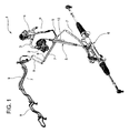
figure 1 is a representative example of a hydraulic steering system comprising a duct according to the present invention; -
figure 2 is a fluid diagram of a duct according tofigure 1 ; -
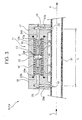
figure 3 is an axial cross-section of an embodiment of a duct according tofigure 1 ; -
figure 4 is a fluid diagram of a duct according to a further embodiment of the present invention; and -
figure 5 is a series of two graphs in which there is comparison of the frequency response curves for a duct without a device for absorption of the low-pressure pulses, and for a duct which is provided with a device according to the present invention, for absorption of the pressure pulses. - In
figure 1, 1 indicates as a whole a hydraulic steering system comprising ahydraulic pump 2, which, by means of suction piping 3, is connected to a work fluid (oil)tank 4. 5 indicates as a whole high-pressure supply piping, which connects the delivery of thepump 2 to a steering box orunit 6, of a type which in itself is known. - A first low-
pressure return duct 7 for the work fluid, which in the example illustrated is produced with alternately flexible and rigid sections, connects the steering box orunit 6 to a cooling coil-type heat exchanger 8, for cooling of this fluid. The outlet of theexchanger 8 is connected to thetank 4 by means of a second return duct, indicated as 9, and also formed by pieces or sections of flexible and rigid piping. - The high-
pressure piping 5 and/or at least one of the low-pressure ducts pipe 10 and anabsorption device 11, which is connected in parallel to the pipe 10 (figure 2 ). - In particular, the
absorption device 11 defines an elongatecylindrical chamber 12 and aninertial element 13, for example a sphere, which is mobile in thechamber 12, and a pair ofsprings inertial element 13 inside thechamber 12. - The
springs inertial element 13 in order to define the position of the latter in both static and dynamic conditions, as will be described in greater detail hereinafter. - The
chamber 12 is connected to thepipe 10 by means of a pair ofconnections inertial element 13 at a distance L along thepipe 10. - In particular, the narrowed parts R1, R2 have respective diameters which are smaller than that of the
pipe 10, such that theconnections - The
inertial element 13 divides thechamber 12 into twocompartments inertial element 13, and are connected to thepipe 10 by means of theconnection 16 and theconnection 17 respectively. In addition, thecompartments chamber 12, by means of a passage P. - The passage P disconnects the pressure of the
compartment 12a from that of thecompartment 12b, and is provided, for example, by means of an annular channel defined between theinertial element 13 and alateral wall 18 of thechamber 12. - According to a preferred embodiment illustrated in
figure 3 , theabsorption device 11 comprises the twoconnections respective apertures pipe 10 and a rigid, substantially tubularintermediate element 22 which is interposed between theconnections - Through the
connections respective ducts duct 23 of theconnection 16 has twosections section 23a is connected to thepipe 10 and thesection 23b extends parallel to this pipe, and opens inside the intermediatetubular element 22. - Similarly, the
duct 24 of the terminal element 21 has twosections pipe 10 at a distance L from theaperture 12 in thepiping 5, and the latter opens inside the intermediatetubular element 22. - In the embodiment illustrated, the
connections protuberances tubular element 22, with interposition of respective "O"-ring seals. - Inside the intermediate
tubular element 22, between said protuberances of theconnections chamber 12 which by means of theducts pipe 10. - In the
chamber 12 there is fitted theinertial element 13 comprising apiston 26, which in the example illustrated is substantially cylindrical. From the opposite sides of thepiston 26 there extend two axially alignedrods piston 26 is fitted such as to be mobile in thechamber 12, and defines the passage P in order to permit the leakage of the fluid between thecompartments - This leakage can be made possible by the effect of radial play between the
piston 26 and thelateral wall 18 of thechamber 12, and/or by other arrangements such as holes or notches in its periphery. - The
springs piston 26, respectively around therod 27 and therod 28. -
Figure 4 illustrates the diagram of a high- or low-pressure duct 30 according to a further embodiment of the present invention, in which the components which are functionally identical to the components of the duct 1 are indicated by the same reference numbers as those used in the description of the high-pressure piping 5. - In particular, the
duct 30 comprises thepipe 10 and anabsorption device 31 which defines thechamber 12, and comprises theconnections cylindrical drawer 32 which slides in thechamber 12, and thesprings - The
drawer 32 defines an axial through hole which constitutes the passage P and permits the absorption action by means of the transfer of work fluid between thecompartment 12a and thecompartment 12b inside thechamber 12. - In use, the
pipe 10 and theabsorption device pressure piping 5 in order to absorb efficiently the pressure pulses generated by the irregularity of rotation of the shaft with bends, and/or along at least one of the low-pressure ducts - In a condition of rest, the pressure of the work fluid in the
chamber 12 is hydrostatic, and the position of theinertial element 13 is determined exclusively by the balance of the forces applied respectively by thesprings - When the work fluid flows in the
pipe 10 as illustrated by the arrow F, the pressure pulse of thepipe 10 is transmitted inside thecompartments respective connections inertial element 13. In particular, theinertial element 13 is subjected to the action of the relative pressure derived from the difference in the absolute pressures which are present respectively in thecompartments - The
absorption device inertial element 13, and the stiffness is defined by the pair ofsprings springs inertial element 13 can be such as to obtain a resonant system which is extremely efficient in dissipating the energy of the pulses which are derived from thepipe 10, and have frequencies contained in a low-frequency interval which depends on the aforementioned ratio. - Narrowed parts R1, R2 avoid that a considerable quantity of fluid flows in
device 11 and allow, at least theoretically, that only a pressure signal propagates inchamber 12. It is therefore avoided that an excessive amount of fluid is accumulated inchamber 12. - In addition, the passage P defines localised hydraulic resistance by means of which the work fluid is blown by, in order to absorb the oscillation of the
inertial element 13. - The effect of the
absorption device pipe 10 can be determined experimentally, or it can be investigated analytically on the basis of a suitable mathematical model. - The two graphs in
figure 5 compare (when there is variation of the frequency f recorded on the x-axis) developments of the amplitude A and of the phase f of the vibration for a duct without thedevice 11, 31 (curves in a thin line) and for a duct provided with thedevice - Analysis of the diagrams in
figure 5 makes it possible to see easily that in the field of frequencies between 20 Hz and 70 Hz, the presence of thedevice - The solution according to the invention substantially makes it possible to eliminate the low-frequency resonance peaks, whilst maintaining unaltered the layout of the high-pressure supply piping. This therefore provides an optimum compromise between compactness and strength.
- The advantages which the ducts previously described make it possible to obtain are as follows.
- Seeing that
absorption device absorption device pipe 10, inside which the conventional quarter-wave silencer pipes can be fitted. In addition, theabsorption device - Finally, it is apparent that modifications and variations can be made to the ducts described and illustrated, without departing from the protective scope of the present invention, as defined in the attached claims.
- For example, in a non-limiting embodiment, the
chamber 12 is defined by a flexible pipe comprising a layer of polymer material, for example by a piece of pipe for the high-pressure branch of a hydraulic steering system.
Claims (8)
- Duct (5; 7; 9; 30) for a hydraulic steering system of a motor vehicle, comprising a pipe (10) for feeding a fluid and a device (11; 31) for absorption of the fluid pressure pulses, wherein said device (11; 31) comprises a chamber (12) which is connected in parallel to said pipe (10) by means of a first and a second connection (16, 17), an inertial element (13) which is mobile inside said chamber (12), resilient means (14; 15) acting on said inertial element (13) in order to maintain said inertial element (13) in an intermediate position, such as to define a first and a second compartment (12a, 12b) inside the chamber (12), characterised by a passage (P) set inside said chamber (12) to connect said compartments (12a, 12b) to one another in order to permit leakage of fluid while said inertial element (13) is moving, wherein at least one of said first and second connections (16, 17) defines a narrowed part (R1, R2) with a diameter smaller than that of pipe (10).
- Duct (5; 7; 9; 30) according to claim 1, characterised in that also the other of said first and second connections (16, 17) defines a second narrowed part (R1, R2).
- Duct (5; 7; 9; 30) according to any of the preceding claims, characterised in that said resilient means comprise a first and a second spring (14, 15) which are fitted opposite one another relative to said inertial element (13).
- Duct (5; 7; 9) according to any one of the preceding claims, characterised in that said passage (P) is a channel defined between said inertial element (13) and a lateral wall (18) which defines said chamber (12).
- Duct (5; 7; 9) according to claim 4, characterised in that said inertial element (13) comprises a piston (26).
- Duct (5; 7; 9) according to claims 3 and 5, characterised in that said piston (26) comprises a first and second rod (27, 28) which are opposite one another, and in that said first and second springs (14, 15) are helical springs, and surround respectively said first and second rods (27, 28).
- Duct (30) according to any one of claims 1 to 3, characterised in that said passage (P) is a through hole defined by said inertial element (13).
- Duct (30) according to any one of the preceding claims, characterised in that said first and second connections (16, 17) have respective facing protuberances (16a, 17a), which engage in a manner sealed against fluid in the opposite ends of a rigid intermediate tubular element (22) which defines said chamber (12).
Applications Claiming Priority (2)
| Application Number | Priority Date | Filing Date | Title |
|---|---|---|---|
| IT000445A ITTO20070445A1 (en) | 2007-06-20 | 2007-06-20 | CONDUCT PROVIDED WITH A DEVICE FOR DAMPING THE PRESSURE PULSE |
| PCT/IB2008/001607 WO2008155641A1 (en) | 2007-06-20 | 2008-06-19 | Duct provided with a device for absorption of pressure pulses |
Publications (2)
| Publication Number | Publication Date |
|---|---|
| EP2158115A1 EP2158115A1 (en) | 2010-03-03 |
| EP2158115B1 true EP2158115B1 (en) | 2010-12-01 |
Family
ID=38621058
Family Applications (1)
| Application Number | Title | Priority Date | Filing Date |
|---|---|---|---|
| EP08762924A Not-in-force EP2158115B1 (en) | 2007-06-20 | 2008-06-19 | Duct provided with a device for absorption of pressure pulses |
Country Status (9)
| Country | Link |
|---|---|
| US (1) | US20100288388A1 (en) |
| EP (1) | EP2158115B1 (en) |
| CN (1) | CN101801763B (en) |
| AT (1) | ATE490151T1 (en) |
| BR (1) | BRPI0811803A2 (en) |
| DE (1) | DE602008003802D1 (en) |
| ES (1) | ES2356421T3 (en) |
| IT (1) | ITTO20070445A1 (en) |
| WO (1) | WO2008155641A1 (en) |
Families Citing this family (14)
| Publication number | Priority date | Publication date | Assignee | Title |
|---|---|---|---|---|
| KR101197467B1 (en) * | 2010-08-23 | 2012-11-09 | 주식회사 만도 | Hydraulic break system |
| RU2011101629A (en) * | 2011-01-18 | 2012-07-27 | Валентин Иванович Лалабеков (RU) | METHOD FOR EXTINGUISHING PRESSURE PIPELINE VIBRATIONS |
| RU2011101829A (en) * | 2011-01-20 | 2012-07-27 | Общество с ограниченной ответственностью "ТехПромАрма" (RU) | PRESSURE STABILIZER |
| EP2665962A4 (en) * | 2011-01-21 | 2014-11-12 | Fluid Kinnect Pty Ltd | Water hammer arrester |
| JP5595457B2 (en) * | 2012-09-05 | 2014-09-24 | 東海ゴム工業株式会社 | connector |
| CN102837734B (en) * | 2012-09-20 | 2014-08-06 | 荆州恒隆汽车零部件制造有限公司 | Liquid current regulator for improving hydraulic pressure noise abnormity of steering gear |
| DE102013000338A1 (en) * | 2013-01-11 | 2014-07-17 | Mann + Hummel Gmbh | pulsation dampers |
| RU2531483C1 (en) * | 2013-07-31 | 2014-10-20 | Общество с ограниченной ответственностью "ТехПромАрма" | Self-killing of shock pulses of transferred medium in main pipeline |
| GB2533857B (en) * | 2013-08-22 | 2020-06-03 | Halliburton Energy Services Inc | Magnetic pressure pulse attenuation |
| CN103759094B (en) * | 2014-02-10 | 2016-06-08 | 安徽江淮汽车股份有限公司 | A kind of pipeline for clutch system |
| US9863421B2 (en) * | 2014-04-19 | 2018-01-09 | Emerson Climate Technologies, Inc. | Pulsation dampening assembly |
| US10400800B2 (en) * | 2015-03-10 | 2019-09-03 | Hydac Technology Gmbh | Damping device |
| CN110307216A (en) * | 2019-03-28 | 2019-10-08 | 潍柴动力股份有限公司 | Reduce the method for Noise of Hydraulic System and the noise reduction T-joint for hydraulic system |
| KR102732814B1 (en) * | 2020-07-09 | 2024-11-20 | 현대모비스 주식회사 | Braking Apparatus for Vehicle |
Family Cites Families (16)
| Publication number | Priority date | Publication date | Assignee | Title |
|---|---|---|---|---|
| US1974884A (en) * | 1931-02-27 | 1934-09-25 | Opel Fritz Von | Steering apparatus for aircraft |
| US2601616A (en) * | 1950-06-17 | 1952-06-24 | Bendix Aviat Corp | Fluid filtering and metering unit |
| US2678066A (en) * | 1951-05-15 | 1954-05-11 | J C Carter Company | Fluid flow control device |
| GB883161A (en) * | 1959-05-13 | 1961-11-22 | Volvo Ab | Improvements in hydropneumatic suspension and damping devices for vehicles |
| US3489172A (en) * | 1967-05-22 | 1970-01-13 | Henry B Whitmore | Linear pressure bleed regulator |
| US3550912A (en) * | 1968-02-15 | 1970-12-29 | Mikhail Alexeevich Melnikov Ei | Emulsifier |
| US3648570A (en) * | 1970-06-22 | 1972-03-14 | Ltv Aerospace Corp | Apparatus for damping resonant vibration |
| US5667285A (en) * | 1995-07-28 | 1997-09-16 | General Motors Corporation | Central hydraulics brake system |
| US5740837A (en) * | 1996-11-05 | 1998-04-21 | Chiang; Swea Tong | Means for automatically regulating water pressure in water pipe |
| US6112768A (en) * | 1999-04-08 | 2000-09-05 | Rath; Leslie B. | In-line fluid agitator |
| DE10221276B4 (en) * | 2002-05-14 | 2005-05-19 | Eaton Fluid Power Gmbh | Hydraulic system with pressure-dependent damping |
| US6755703B1 (en) * | 2003-01-03 | 2004-06-29 | Brunswick Corporation | Hydraulically assisted gear shift mechanism for a marine propulsion device |
| GB0307808D0 (en) * | 2003-04-04 | 2003-05-07 | Eaton Corp | Hydraulic system |
| DE10352689A1 (en) * | 2003-11-12 | 2005-06-23 | Bayerische Motoren Werke Ag | Hydraulic pressure surge shut-off valve especially for servo steering system of motor vehicle has hydraulic source pressure acting on one end face of shut-off piston and hydraulic medium from working cylinder acting on other end face |
| DE102004045100A1 (en) * | 2004-09-17 | 2006-03-23 | Audi Ag | Damper for damping pressure vibrations in hydraulic system, has single piece housing with working chamber and piston positionable in working chamber using spring units that axially support itself at cover wall and base wall |
| JP2009119901A (en) * | 2007-11-12 | 2009-06-04 | Hitachi Ltd | Power steering device |
-
2007
- 2007-06-20 IT IT000445A patent/ITTO20070445A1/en unknown
-
2008
- 2008-06-19 US US12/665,520 patent/US20100288388A1/en not_active Abandoned
- 2008-06-19 EP EP08762924A patent/EP2158115B1/en not_active Not-in-force
- 2008-06-19 DE DE602008003802T patent/DE602008003802D1/en active Active
- 2008-06-19 CN CN2008800252838A patent/CN101801763B/en not_active Expired - Fee Related
- 2008-06-19 ES ES08762924T patent/ES2356421T3/en active Active
- 2008-06-19 BR BRPI0811803-5A2A patent/BRPI0811803A2/en not_active IP Right Cessation
- 2008-06-19 AT AT08762924T patent/ATE490151T1/en not_active IP Right Cessation
- 2008-06-19 WO PCT/IB2008/001607 patent/WO2008155641A1/en not_active Ceased
Also Published As
| Publication number | Publication date |
|---|---|
| DE602008003802D1 (en) | 2011-01-13 |
| EP2158115A1 (en) | 2010-03-03 |
| WO2008155641A1 (en) | 2008-12-24 |
| ES2356421T3 (en) | 2011-04-08 |
| BRPI0811803A2 (en) | 2014-11-11 |
| ITTO20070445A1 (en) | 2008-12-21 |
| CN101801763B (en) | 2012-01-04 |
| ATE490151T1 (en) | 2010-12-15 |
| US20100288388A1 (en) | 2010-11-18 |
| CN101801763A (en) | 2010-08-11 |
Similar Documents
| Publication | Publication Date | Title |
|---|---|---|
| US20100288388A1 (en) | Duct provided with a device for absorption of pressure pulses | |
| US10196947B2 (en) | Muffler | |
| CN103062569B (en) | A kind of Pressure-auto-balanchydrodynamic hydrodynamic noise silencer | |
| CN104047990B (en) | shock absorber | |
| RU2260707C2 (en) | Hydraulic line flat tubular liquid pressure fluctuation damper | |
| Lu et al. | Pilot study on compact wideband micro-perforated muffler with a serial-parallel coupling mode | |
| Wu et al. | Modeling and experimental verification of a new muffler based on the theory of quarter-wavelength tube and the Helmholtz muffler | |
| KR101565233B1 (en) | Pressure pulsation dampening device | |
| Pal et al. | Design of a muffler & effect of resonator length for 3 cylinder SI engine | |
| US10024426B2 (en) | Transmission arrangement | |
| US12203463B2 (en) | Device for damping pressure pulsations for a compressor of a caseous fluid | |
| JPS60159381A (en) | Hydraulic system of vehicle | |
| Dodson et al. | Experimental investigation of quarter wavelength silencers in large-scale hydraulic systems | |
| Motlagh et al. | Application of smart materials for noise and vibration of hydraulic systems | |
| CN114183619B (en) | Noise reduction structure for reducing fuel pulsation exciting force based on vibration damper | |
| CN121438790A (en) | Noise reduction units, noise reduction structures, and control methods and devices for engineering vehicles | |
| RU211847U1 (en) | Combined dampening device for low-frequency noise and pressure fluctuations | |
| Zhao et al. | Structural design of hydraulic pipeline secondary source in active pulsation control system | |
| CN202082161U (en) | Compound water muffler for centrifugal pump | |
| Młynarczyk et al. | In-Line Sphere Arrays as Pressure Pulsation and Pipeline Vibration Dampers in Reciprocating Compressor Manifold | |
| Buryan et al. | Evaluating the effectiveness of vibration isolation using hydro pneumatic spring with inertial motion converter | |
| JP3653166B2 (en) | Fluid pulsation reduction device | |
| Pan et al. | Optimal design of a control actuator for sound attenuation in a piping system excited by a positive displacement pump | |
| Danes | Computational Methods for Designing New Passive Fluid Borne Noise Source Reduction Strategies in Hydraulic Systems | |
| RU2177555C2 (en) | Multicylinder internal combustion engine |
Legal Events
| Date | Code | Title | Description |
|---|---|---|---|
| PUAI | Public reference made under article 153(3) epc to a published international application that has entered the european phase |
Free format text: ORIGINAL CODE: 0009012 |
|
| 17P | Request for examination filed |
Effective date: 20091221 |
|
| AK | Designated contracting states |
Kind code of ref document: A1 Designated state(s): AT BE BG CH CY CZ DE DK EE ES FI FR GB GR HR HU IE IS IT LI LT LU LV MC MT NL NO PL PT RO SE SI SK TR |
|
| AX | Request for extension of the european patent |
Extension state: AL BA MK RS |
|
| GRAP | Despatch of communication of intention to grant a patent |
Free format text: ORIGINAL CODE: EPIDOSNIGR1 |
|
| DAX | Request for extension of the european patent (deleted) | ||
| GRAS | Grant fee paid |
Free format text: ORIGINAL CODE: EPIDOSNIGR3 |
|
| GRAA | (expected) grant |
Free format text: ORIGINAL CODE: 0009210 |
|
| RIN1 | Information on inventor provided before grant (corrected) |
Inventor name: ZANARDI, MARIOFELICE Inventor name: BARALE, EMANUELE |
|
| AK | Designated contracting states |
Kind code of ref document: B1 Designated state(s): AT BE BG CH CY CZ DE DK EE ES FI FR GB GR HR HU IE IS IT LI LT LU LV MC MT NL NO PL PT RO SE SI SK TR |
|
| REG | Reference to a national code |
Ref country code: GB Ref legal event code: FG4D |
|
| REG | Reference to a national code |
Ref country code: CH Ref legal event code: EP |
|
| REG | Reference to a national code |
Ref country code: IE Ref legal event code: FG4D |
|
| REF | Corresponds to: |
Ref document number: 602008003802 Country of ref document: DE Date of ref document: 20110113 Kind code of ref document: P |
|
| REG | Reference to a national code |
Ref country code: RO Ref legal event code: EPE |
|
| REG | Reference to a national code |
Ref country code: NL Ref legal event code: VDEP Effective date: 20101201 |
|
| REG | Reference to a national code |
Ref country code: ES Ref legal event code: FG2A Ref document number: 2356421 Country of ref document: ES Kind code of ref document: T3 Effective date: 20110408 |
|
| PG25 | Lapsed in a contracting state [announced via postgrant information from national office to epo] |
Ref country code: NO Free format text: LAPSE BECAUSE OF FAILURE TO SUBMIT A TRANSLATION OF THE DESCRIPTION OR TO PAY THE FEE WITHIN THE PRESCRIBED TIME-LIMIT Effective date: 20110301 Ref country code: LT Free format text: LAPSE BECAUSE OF FAILURE TO SUBMIT A TRANSLATION OF THE DESCRIPTION OR TO PAY THE FEE WITHIN THE PRESCRIBED TIME-LIMIT Effective date: 20101201 |
|
| LTIE | Lt: invalidation of european patent or patent extension |
Effective date: 20101201 |
|
| PG25 | Lapsed in a contracting state [announced via postgrant information from national office to epo] |
Ref country code: SI Free format text: LAPSE BECAUSE OF FAILURE TO SUBMIT A TRANSLATION OF THE DESCRIPTION OR TO PAY THE FEE WITHIN THE PRESCRIBED TIME-LIMIT Effective date: 20101201 Ref country code: FI Free format text: LAPSE BECAUSE OF FAILURE TO SUBMIT A TRANSLATION OF THE DESCRIPTION OR TO PAY THE FEE WITHIN THE PRESCRIBED TIME-LIMIT Effective date: 20101201 Ref country code: SE Free format text: LAPSE BECAUSE OF FAILURE TO SUBMIT A TRANSLATION OF THE DESCRIPTION OR TO PAY THE FEE WITHIN THE PRESCRIBED TIME-LIMIT Effective date: 20101201 Ref country code: CY Free format text: LAPSE BECAUSE OF FAILURE TO SUBMIT A TRANSLATION OF THE DESCRIPTION OR TO PAY THE FEE WITHIN THE PRESCRIBED TIME-LIMIT Effective date: 20101201 Ref country code: NL Free format text: LAPSE BECAUSE OF FAILURE TO SUBMIT A TRANSLATION OF THE DESCRIPTION OR TO PAY THE FEE WITHIN THE PRESCRIBED TIME-LIMIT Effective date: 20101201 Ref country code: HR Free format text: LAPSE BECAUSE OF FAILURE TO SUBMIT A TRANSLATION OF THE DESCRIPTION OR TO PAY THE FEE WITHIN THE PRESCRIBED TIME-LIMIT Effective date: 20101201 Ref country code: BG Free format text: LAPSE BECAUSE OF FAILURE TO SUBMIT A TRANSLATION OF THE DESCRIPTION OR TO PAY THE FEE WITHIN THE PRESCRIBED TIME-LIMIT Effective date: 20110301 Ref country code: AT Free format text: LAPSE BECAUSE OF FAILURE TO SUBMIT A TRANSLATION OF THE DESCRIPTION OR TO PAY THE FEE WITHIN THE PRESCRIBED TIME-LIMIT Effective date: 20101201 Ref country code: LV Free format text: LAPSE BECAUSE OF FAILURE TO SUBMIT A TRANSLATION OF THE DESCRIPTION OR TO PAY THE FEE WITHIN THE PRESCRIBED TIME-LIMIT Effective date: 20101201 |
|
| PG25 | Lapsed in a contracting state [announced via postgrant information from national office to epo] |
Ref country code: GR Free format text: LAPSE BECAUSE OF FAILURE TO SUBMIT A TRANSLATION OF THE DESCRIPTION OR TO PAY THE FEE WITHIN THE PRESCRIBED TIME-LIMIT Effective date: 20110302 |
|
| PG25 | Lapsed in a contracting state [announced via postgrant information from national office to epo] |
Ref country code: CZ Free format text: LAPSE BECAUSE OF FAILURE TO SUBMIT A TRANSLATION OF THE DESCRIPTION OR TO PAY THE FEE WITHIN THE PRESCRIBED TIME-LIMIT Effective date: 20101201 Ref country code: BE Free format text: LAPSE BECAUSE OF FAILURE TO SUBMIT A TRANSLATION OF THE DESCRIPTION OR TO PAY THE FEE WITHIN THE PRESCRIBED TIME-LIMIT Effective date: 20101201 Ref country code: IS Free format text: LAPSE BECAUSE OF FAILURE TO SUBMIT A TRANSLATION OF THE DESCRIPTION OR TO PAY THE FEE WITHIN THE PRESCRIBED TIME-LIMIT Effective date: 20110401 Ref country code: EE Free format text: LAPSE BECAUSE OF FAILURE TO SUBMIT A TRANSLATION OF THE DESCRIPTION OR TO PAY THE FEE WITHIN THE PRESCRIBED TIME-LIMIT Effective date: 20101201 Ref country code: PT Free format text: LAPSE BECAUSE OF FAILURE TO SUBMIT A TRANSLATION OF THE DESCRIPTION OR TO PAY THE FEE WITHIN THE PRESCRIBED TIME-LIMIT Effective date: 20110401 |
|
| PG25 | Lapsed in a contracting state [announced via postgrant information from national office to epo] |
Ref country code: SK Free format text: LAPSE BECAUSE OF FAILURE TO SUBMIT A TRANSLATION OF THE DESCRIPTION OR TO PAY THE FEE WITHIN THE PRESCRIBED TIME-LIMIT Effective date: 20101201 Ref country code: PL Free format text: LAPSE BECAUSE OF FAILURE TO SUBMIT A TRANSLATION OF THE DESCRIPTION OR TO PAY THE FEE WITHIN THE PRESCRIBED TIME-LIMIT Effective date: 20101201 |
|
| PLBE | No opposition filed within time limit |
Free format text: ORIGINAL CODE: 0009261 |
|
| STAA | Information on the status of an ep patent application or granted ep patent |
Free format text: STATUS: NO OPPOSITION FILED WITHIN TIME LIMIT |
|
| PG25 | Lapsed in a contracting state [announced via postgrant information from national office to epo] |
Ref country code: DK Free format text: LAPSE BECAUSE OF FAILURE TO SUBMIT A TRANSLATION OF THE DESCRIPTION OR TO PAY THE FEE WITHIN THE PRESCRIBED TIME-LIMIT Effective date: 20101201 |
|
| 26N | No opposition filed |
Effective date: 20110902 |
|
| REG | Reference to a national code |
Ref country code: DE Ref legal event code: R097 Ref document number: 602008003802 Country of ref document: DE Effective date: 20110902 |
|
| PG25 | Lapsed in a contracting state [announced via postgrant information from national office to epo] |
Ref country code: IT Free format text: LAPSE BECAUSE OF FAILURE TO SUBMIT A TRANSLATION OF THE DESCRIPTION OR TO PAY THE FEE WITHIN THE PRESCRIBED TIME-LIMIT Effective date: 20101201 Ref country code: MT Free format text: LAPSE BECAUSE OF FAILURE TO SUBMIT A TRANSLATION OF THE DESCRIPTION OR TO PAY THE FEE WITHIN THE PRESCRIBED TIME-LIMIT Effective date: 20101201 |
|
| REG | Reference to a national code |
Ref country code: IE Ref legal event code: MM4A |
|
| PG25 | Lapsed in a contracting state [announced via postgrant information from national office to epo] |
Ref country code: IE Free format text: LAPSE BECAUSE OF NON-PAYMENT OF DUE FEES Effective date: 20110619 |
|
| REG | Reference to a national code |
Ref country code: CH Ref legal event code: PL |
|
| REG | Reference to a national code |
Ref country code: CH Ref legal event code: PL |
|
| GBPC | Gb: european patent ceased through non-payment of renewal fee |
Effective date: 20120619 |
|
| PG25 | Lapsed in a contracting state [announced via postgrant information from national office to epo] |
Ref country code: CH Free format text: LAPSE BECAUSE OF NON-PAYMENT OF DUE FEES Effective date: 20120630 Ref country code: MC Free format text: LAPSE BECAUSE OF NON-PAYMENT OF DUE FEES Effective date: 20110630 Ref country code: LI Free format text: LAPSE BECAUSE OF NON-PAYMENT OF DUE FEES Effective date: 20120630 Ref country code: GB Free format text: LAPSE BECAUSE OF NON-PAYMENT OF DUE FEES Effective date: 20120619 |
|
| PG25 | Lapsed in a contracting state [announced via postgrant information from national office to epo] |
Ref country code: LU Free format text: LAPSE BECAUSE OF NON-PAYMENT OF DUE FEES Effective date: 20110619 |
|
| PGFP | Annual fee paid to national office [announced via postgrant information from national office to epo] |
Ref country code: DE Payment date: 20130619 Year of fee payment: 6 |
|
| PGFP | Annual fee paid to national office [announced via postgrant information from national office to epo] |
Ref country code: TR Payment date: 20130619 Year of fee payment: 6 Ref country code: RO Payment date: 20130612 Year of fee payment: 6 |
|
| PG25 | Lapsed in a contracting state [announced via postgrant information from national office to epo] |
Ref country code: HU Free format text: LAPSE BECAUSE OF FAILURE TO SUBMIT A TRANSLATION OF THE DESCRIPTION OR TO PAY THE FEE WITHIN THE PRESCRIBED TIME-LIMIT Effective date: 20101201 |
|
| PGFP | Annual fee paid to national office [announced via postgrant information from national office to epo] |
Ref country code: ES Payment date: 20130628 Year of fee payment: 6 |
|
| PGFP | Annual fee paid to national office [announced via postgrant information from national office to epo] |
Ref country code: FR Payment date: 20130719 Year of fee payment: 6 |
|
| REG | Reference to a national code |
Ref country code: DE Ref legal event code: R119 Ref document number: 602008003802 Country of ref document: DE |
|
| PG25 | Lapsed in a contracting state [announced via postgrant information from national office to epo] |
Ref country code: RO Free format text: LAPSE BECAUSE OF NON-PAYMENT OF DUE FEES Effective date: 20140619 |
|
| REG | Reference to a national code |
Ref country code: DE Ref legal event code: R119 Ref document number: 602008003802 Country of ref document: DE Effective date: 20150101 |
|
| REG | Reference to a national code |
Ref country code: FR Ref legal event code: ST Effective date: 20150227 |
|
| PG25 | Lapsed in a contracting state [announced via postgrant information from national office to epo] |
Ref country code: DE Free format text: LAPSE BECAUSE OF NON-PAYMENT OF DUE FEES Effective date: 20150101 |
|
| PG25 | Lapsed in a contracting state [announced via postgrant information from national office to epo] |
Ref country code: FR Free format text: LAPSE BECAUSE OF NON-PAYMENT OF DUE FEES Effective date: 20140630 |
|
| REG | Reference to a national code |
Ref country code: ES Ref legal event code: FD2A Effective date: 20150724 |
|
| PG25 | Lapsed in a contracting state [announced via postgrant information from national office to epo] |
Ref country code: ES Free format text: LAPSE BECAUSE OF NON-PAYMENT OF DUE FEES Effective date: 20140620 |
|
| PG25 | Lapsed in a contracting state [announced via postgrant information from national office to epo] |
Ref country code: TR Free format text: LAPSE BECAUSE OF NON-PAYMENT OF DUE FEES Effective date: 20140619 |