EP2157708A1 - Data retransmission method and radio communication system adopting same - Google Patents
Data retransmission method and radio communication system adopting same Download PDFInfo
- Publication number
- EP2157708A1 EP2157708A1 EP07737195A EP07737195A EP2157708A1 EP 2157708 A1 EP2157708 A1 EP 2157708A1 EP 07737195 A EP07737195 A EP 07737195A EP 07737195 A EP07737195 A EP 07737195A EP 2157708 A1 EP2157708 A1 EP 2157708A1
- Authority
- EP
- European Patent Office
- Prior art keywords
- transmission
- data
- retransmission
- beamforming
- errors
- Prior art date
- Legal status (The legal status is an assumption and is not a legal conclusion. Google has not performed a legal analysis and makes no representation as to the accuracy of the status listed.)
- Withdrawn
Links
Images









Classifications
-
- H—ELECTRICITY
- H04—ELECTRIC COMMUNICATION TECHNIQUE
- H04L—TRANSMISSION OF DIGITAL INFORMATION, e.g. TELEGRAPHIC COMMUNICATION
- H04L1/00—Arrangements for detecting or preventing errors in the information received
- H04L1/02—Arrangements for detecting or preventing errors in the information received by diversity reception
- H04L1/06—Arrangements for detecting or preventing errors in the information received by diversity reception using space diversity
-
- H—ELECTRICITY
- H04—ELECTRIC COMMUNICATION TECHNIQUE
- H04B—TRANSMISSION
- H04B7/00—Radio transmission systems, i.e. using radiation field
- H04B7/02—Diversity systems; Multi-antenna system, i.e. transmission or reception using multiple antennas
- H04B7/04—Diversity systems; Multi-antenna system, i.e. transmission or reception using multiple antennas using two or more spaced independent antennas
- H04B7/06—Diversity systems; Multi-antenna system, i.e. transmission or reception using multiple antennas using two or more spaced independent antennas at the transmitting station
- H04B7/0613—Diversity systems; Multi-antenna system, i.e. transmission or reception using multiple antennas using two or more spaced independent antennas at the transmitting station using simultaneous transmission
- H04B7/0615—Diversity systems; Multi-antenna system, i.e. transmission or reception using multiple antennas using two or more spaced independent antennas at the transmitting station using simultaneous transmission of weighted versions of same signal
- H04B7/0617—Diversity systems; Multi-antenna system, i.e. transmission or reception using multiple antennas using two or more spaced independent antennas at the transmitting station using simultaneous transmission of weighted versions of same signal for beam forming
-
- H—ELECTRICITY
- H04—ELECTRIC COMMUNICATION TECHNIQUE
- H04B—TRANSMISSION
- H04B7/00—Radio transmission systems, i.e. using radiation field
- H04B7/02—Diversity systems; Multi-antenna system, i.e. transmission or reception using multiple antennas
- H04B7/04—Diversity systems; Multi-antenna system, i.e. transmission or reception using multiple antennas using two or more spaced independent antennas
- H04B7/06—Diversity systems; Multi-antenna system, i.e. transmission or reception using multiple antennas using two or more spaced independent antennas at the transmitting station
- H04B7/0613—Diversity systems; Multi-antenna system, i.e. transmission or reception using multiple antennas using two or more spaced independent antennas at the transmitting station using simultaneous transmission
- H04B7/0615—Diversity systems; Multi-antenna system, i.e. transmission or reception using multiple antennas using two or more spaced independent antennas at the transmitting station using simultaneous transmission of weighted versions of same signal
- H04B7/0619—Diversity systems; Multi-antenna system, i.e. transmission or reception using multiple antennas using two or more spaced independent antennas at the transmitting station using simultaneous transmission of weighted versions of same signal using feedback from receiving side
- H04B7/0621—Feedback content
- H04B7/0634—Antenna weights or vector/matrix coefficients
-
- H—ELECTRICITY
- H04—ELECTRIC COMMUNICATION TECHNIQUE
- H04B—TRANSMISSION
- H04B7/00—Radio transmission systems, i.e. using radiation field
- H04B7/02—Diversity systems; Multi-antenna system, i.e. transmission or reception using multiple antennas
- H04B7/04—Diversity systems; Multi-antenna system, i.e. transmission or reception using multiple antennas using two or more spaced independent antennas
- H04B7/06—Diversity systems; Multi-antenna system, i.e. transmission or reception using multiple antennas using two or more spaced independent antennas at the transmitting station
- H04B7/0613—Diversity systems; Multi-antenna system, i.e. transmission or reception using multiple antennas using two or more spaced independent antennas at the transmitting station using simultaneous transmission
- H04B7/0615—Diversity systems; Multi-antenna system, i.e. transmission or reception using multiple antennas using two or more spaced independent antennas at the transmitting station using simultaneous transmission of weighted versions of same signal
- H04B7/0619—Diversity systems; Multi-antenna system, i.e. transmission or reception using multiple antennas using two or more spaced independent antennas at the transmitting station using simultaneous transmission of weighted versions of same signal using feedback from receiving side
- H04B7/0658—Feedback reduction
-
- H—ELECTRICITY
- H04—ELECTRIC COMMUNICATION TECHNIQUE
- H04B—TRANSMISSION
- H04B7/00—Radio transmission systems, i.e. using radiation field
- H04B7/02—Diversity systems; Multi-antenna system, i.e. transmission or reception using multiple antennas
- H04B7/04—Diversity systems; Multi-antenna system, i.e. transmission or reception using multiple antennas using two or more spaced independent antennas
- H04B7/06—Diversity systems; Multi-antenna system, i.e. transmission or reception using multiple antennas using two or more spaced independent antennas at the transmitting station
- H04B7/0613—Diversity systems; Multi-antenna system, i.e. transmission or reception using multiple antennas using two or more spaced independent antennas at the transmitting station using simultaneous transmission
- H04B7/0667—Diversity systems; Multi-antenna system, i.e. transmission or reception using multiple antennas using two or more spaced independent antennas at the transmitting station using simultaneous transmission of delayed versions of same signal
- H04B7/0669—Diversity systems; Multi-antenna system, i.e. transmission or reception using multiple antennas using two or more spaced independent antennas at the transmitting station using simultaneous transmission of delayed versions of same signal using different channel coding between antennas
-
- H—ELECTRICITY
- H04—ELECTRIC COMMUNICATION TECHNIQUE
- H04B—TRANSMISSION
- H04B7/00—Radio transmission systems, i.e. using radiation field
- H04B7/02—Diversity systems; Multi-antenna system, i.e. transmission or reception using multiple antennas
- H04B7/04—Diversity systems; Multi-antenna system, i.e. transmission or reception using multiple antennas using two or more spaced independent antennas
- H04B7/06—Diversity systems; Multi-antenna system, i.e. transmission or reception using multiple antennas using two or more spaced independent antennas at the transmitting station
- H04B7/0686—Hybrid systems, i.e. switching and simultaneous transmission
- H04B7/0689—Hybrid systems, i.e. switching and simultaneous transmission using different transmission schemes, at least one of them being a diversity transmission scheme
-
- H—ELECTRICITY
- H04—ELECTRIC COMMUNICATION TECHNIQUE
- H04L—TRANSMISSION OF DIGITAL INFORMATION, e.g. TELEGRAPHIC COMMUNICATION
- H04L1/00—Arrangements for detecting or preventing errors in the information received
- H04L1/0001—Systems modifying transmission characteristics according to link quality, e.g. power backoff
- H04L1/0002—Systems modifying transmission characteristics according to link quality, e.g. power backoff by adapting the transmission rate
- H04L1/0003—Systems modifying transmission characteristics according to link quality, e.g. power backoff by adapting the transmission rate by switching between different modulation schemes
-
- H—ELECTRICITY
- H04—ELECTRIC COMMUNICATION TECHNIQUE
- H04L—TRANSMISSION OF DIGITAL INFORMATION, e.g. TELEGRAPHIC COMMUNICATION
- H04L1/00—Arrangements for detecting or preventing errors in the information received
- H04L1/12—Arrangements for detecting or preventing errors in the information received by using return channel
- H04L1/16—Arrangements for detecting or preventing errors in the information received by using return channel in which the return channel carries supervisory signals, e.g. repetition request signals
- H04L1/18—Automatic repetition systems, e.g. Van Duuren systems
- H04L1/1812—Hybrid protocols; Hybrid automatic repeat request [HARQ]
-
- H—ELECTRICITY
- H04—ELECTRIC COMMUNICATION TECHNIQUE
- H04L—TRANSMISSION OF DIGITAL INFORMATION, e.g. TELEGRAPHIC COMMUNICATION
- H04L1/00—Arrangements for detecting or preventing errors in the information received
- H04L1/12—Arrangements for detecting or preventing errors in the information received by using return channel
- H04L1/16—Arrangements for detecting or preventing errors in the information received by using return channel in which the return channel carries supervisory signals, e.g. repetition request signals
- H04L1/18—Automatic repetition systems, e.g. Van Duuren systems
- H04L1/1867—Arrangements specially adapted for the transmitter end
-
- H—ELECTRICITY
- H04—ELECTRIC COMMUNICATION TECHNIQUE
- H04L—TRANSMISSION OF DIGITAL INFORMATION, e.g. TELEGRAPHIC COMMUNICATION
- H04L1/00—Arrangements for detecting or preventing errors in the information received
- H04L1/12—Arrangements for detecting or preventing errors in the information received by using return channel
- H04L1/16—Arrangements for detecting or preventing errors in the information received by using return channel in which the return channel carries supervisory signals, e.g. repetition request signals
- H04L1/18—Automatic repetition systems, e.g. Van Duuren systems
- H04L1/1867—Arrangements specially adapted for the transmitter end
- H04L1/1893—Physical mapping arrangements
Definitions
- the present invention relates to a data retransmission method, and to a radio communication system employing the same.
- MIMO Multi-Input Multi-Output
- PARC Per Antenna Rate Control
- Non-patent Reference 1 Non-patent Reference 1
- PARC technology handles transmission rates independently for each of multiple antennas, and with respect to retransmission as well, a Cyclic Redundancy Check (CRC) can be added at each transmission antenna and retransmission controlled independently to promote improvement of communication efficiency.
- CRC Cyclic Redundancy Check
- Patent Reference 1 an invention is proposed relating to retransmission at the time of MIMO application enabling different transmission weighting from the initial transmission and obtaining of diversity gain.
- Patent Reference 1 there is no discussion of PARC performing retransmission for each transmission stream, and there is inadequate discussion of retransmission methods when one stream or a plurality of streams are erroneous during transmission of a plurality of streams.
- an object of the present invention is to provide a data retransmission method capable of ensuring QoS (Quality of Service) for services for which retransmission delays cannot be allowed (multicast broadcasts, television conversations, games), as well as a radio communication system employing such a method.
- QoS Quality of Service
- a first mode of a data retransmission method which attains this object of the present invention is a data retransmission method, in a radio communication system having a plurality of transmission systems corresponding to each antenna corresponding to a plurality of segments, in which adaptive modulation is performed according to the propagation quality of a transmission antenna, and a plurality of data streams are transmitted from the plurality of transmission systems, and is characterized in that when there is a transmission error in transmission data in any of the plurality of data streams, transmission data in which the transmission error occurred is simultaneously retransmitted by at least two transmission systems of the plurality of data streams.
- the data retransmission method includes: deciding, when there is a transmission error in each of the transmission data of at least two data streams among the plurality of data streams, the order of retransmission of the transmission data with the transmission errors; and retransmitting the transmission data with the transmission errors, in the decided order, in use of two or more of the transmission systems.
- the data transmission method includes: deciding, when there is a transmission error in each of the transmission data of at least two data streams among the plurality of data streams, the order of retransmission of the transmission data with the transmission errors; and retransmitting the transmission data with the transmission errors, in the decided order, in use of two or more of the transmission systems.
- Fig. 1 illustrates the PARC concept.
- MIMO multiplexing to transmit the data of two different data streams d1 and d2 to be transmitted is shown.
- Control is performed by the AMC (Adaptive Modulation and Coding scheme) control portion 2 to subject each of these data streams d1, d2 to appropriate error encoding and modulation in the error encoding circuits 3a, 3b and adaptive modulation circuits 4a, 4b, according to instructions from a scheduler 1, and the transmission rate of each of the streams is specified.
- AMC Adaptive Modulation and Coding scheme
- the data streams d1 and d2 are passed through without special processing by the weighting portion 5, and are up-converted to the RF band by the transmission RF (Radio Frequency) portions 6a, 6b and are radiated.
- adaptive modulation is not performed only for each transmission antenna; PARC also includes cases in which adaptive modulation is performed for each beam when weighting is performed by the weighting portion 5 and transmission beams are generated. For this reason, the weighting portion 5 is shown in Fig. 1 .
- Signals which have passed through the radio propagation path 10 arrive at the reception antennas Rx1 and Rx2, are down-converted to the baseband (BB) by the reception RF portions 7a and 7b, are demodulated by the demodulation portion 8, and are decoded by the decoding portions 9a and 9b.
- BB baseband
- Decoded data is subjected to a cyclic redundancy check (CRC) for errors by the CRC judgment portions 10a and 10b, to determine whether errors are present.
- CRC cyclic redundancy check
- An ACK or NACK signal is returned to the transmission source according to the CRC judgment result.
- a NACK signal is generated by the retransmission request (HARQ: Hybrid Automatic Repeat reQuest) portions 11a and 11b, and at the same time control is executed to invalidate the output of the decoding portions 9a, 9b.
- HARQ Hybrid Automatic Repeat reQuest
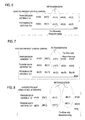
- Fig. 2 shows the circumstances of a data series in a case in which the PARC concept explained using Fig. 1 is employed and there are no reception errors, and shows the manner in which data streams are sent as data series under PARC control.
- the expression d1(n) represents the data of symbol n in the stream d1 transmitted from the transmission antenna Tx1.
- the expression d2(n) represents the data of symbol n in the stream d2 transmitted from the transmission antenna Tx2. If there are no errors, new symbols continue to be transmitted one after another in each of these streams.
- Fig. 3 shows the circumstances of the time series of data when simultaneous errors occur; a case is shown in which errors have occurred in all different streams under PARC control, or in which errors have occurred in MIMO multiplexing without performing CRC judgment for each stream.
- Fig. 3 shows an example in which the previous frame (d1(1), d2(1)) was erroneous, and so in the next frame the same information is retransmitted.
- a SW (Stop and Wait) configuration in which confirmation that the data of the previous frame has arrived before transmitting the next data, or, a GBN (Go Back N) or SR (Selective Repeat) or other method, in which the next data is sent without waiting for confirmation, and retransmission is performed when an error occurs, can be employed.
- HARQ Hybrid Automatic Repeat reQuest
- FIG. 5 shows a method of conventional retransmission under circumstances in which an error occurs in a certain stream portion, in which the stream d1 in which the error has occurred is retransmitted, and new symbols in a stream d2 in which an error has not occurred continue to be sent one after another.
- a method of this invention is a method in which, when retransmitting under circumstances in which an error has occurred in a certain stream portion, symbols of the stream in which the error occurred are transmitted by all the antennas.
- Fig. 6 is a time series diagram showing an example of a data retransmission method according to this invention.
- the symbols of the stream in which the error occurred are transmitted by all antennas.
- Fig. 6 there are two transmission systems, and when an error has occurred in symbol d1(1) in stream d1 transmitted by the first transmission system, the same symbol d1(1) is transmitted from the transmission antennas Tx1 and Tx2 of the two transmission systems.
- transmission diversity technologies such as STBC (Space Time Block Coding), STFC (Space Time Frequency Coding), CDD (Cyclic Delay Diversity), and similar, that is, space coding diversity in which signal points are arranged at each time and at each antenna, are applied, or beamforming technology is applied to obtain a gain, so that errors in retransmission can be greatly reduced.
- STBC Space Time Block Coding
- STFC Space Time Frequency Coding
- CDD Cyclic Delay Diversity
- Fig. 7 is a time series diagram showing an example of a retransmission method according to this invention, for a case in which there are a plurality of transmission antennas, greater in number than two, corresponding to transmission systems greater in number than two.
- Fig. 7 in a case in which an error occurs in symbol d1(1) in a portion of the data stream d1, three transmission antennas Tx1, Tx2, and Tx3 are shown as an example.
- some of the plurality of antennas are used to retransmit the symbol d1(1) of the stream with the error, to reduce errors in retransmission.
- the necessary retransmission gain is adjusted, and the decline in throughput can be held to a minimum.
- Fig. 8 shows an example of another retransmission method according to this invention, and is an example in which errors have occurred simultaneously in a plurality of streams d1 and d2.
- Fig. 9 is an example of extension of the embodiment of Fig. 8 . This is an example of a case in which errors have occurred simultaneously in the symbols d1(1) and d2(1) in the streams d1 and d2 corresponding to the plurality of antennas Tx1 and Tx2, and there exist a plurality of other antennas Tx3 and Tx4 as well.
- transmission diversity or beamforming is applied in retransmission of the symbol d1(1) by the antennas Tx1 and Tx2.
- transmission diversity or beamforming is applied in retransmission of the symbol d2(1) by the plurality of other antennas Tx3 and Tx4.
- Fig. 10 is a further modified example of Fig. 9 ; at the time of retransmission, data may be combined in the same slot and transmitted.
- beamforming is performed using different weights for a plurality of retransmission streams d1(1) and d2(1), and orthogonal space is used in the retransmission.
- orthogonal space is used in the retransmission.
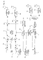
- Fig. 11 shows an example of the configuration of a first transmitter according to the invention.
- the configuration shown in Fig. 11 is the configuration of a transmitter which uses beamforming in performing retransmission.
- feedback signals received by the reception antennas Rx1 and Rx2 are converted to the baseband by the reception RF portions 7a and 7b, are demodulated by the demodulation portion 8, and are decoded by the decoding portion 9.
- the ACK/NACK judgment portion 11 judges whether the previously transmitted symbols were correctly decoded on the receiver side.
- the scheduler 1 When decoding is performed correctly on the receiver side, that is, in the case of an ACK response, the scheduler 1 is notified of sending of the next new data. On the other hand, when decoding could not be performed correctly on the receiver side, that is, in the case of a NACK response, the scheduler 1 is notified of retransmission, and at the same time the weight used in retransmission is extracted by a transmission weight extraction portion 12 for each transmission antenna.
- the scheduler 1 When an ACK response is received and ordinary data transmission is performed, the scheduler 1 notifies a data readout instruction portion 14 and the transmission weight extraction portion 12 of the timing and adaptive modulation information for sending the data. As a result, the state of the start of data transmission is entered.
- the data readout instruction portion 14 retrieves data accumulated in the data buffer 15 in amounts that can be transmitted in each stream, the error encoding circuits 3a, 3b perform CRC encoding, and the AMC control portion 2 controls the modulation circuits 4a, 4b so as to perform adaptive modulation of each stream conforming to the scheduler 1. Further, the modulated signals are input to the weighting portion 5.
- This invention can be implemented whether weights are or are not added, setting the transmission direction, in the weighting portion 5 according to the MIMO multiplexing method.
- the output of the weighting portion 5 is up-converted by the transmission RF portions 6a, 6b, and is emitted from the antennas Tx1, Tx2.
- retrieval is performed for the number of streams transmitted with a certain timing.
- the encoding circuits 3a, 3b add a cyclic redundancy check (CRC) to each stream, and through control by the AMC control portion 2 conforming to the scheduler 1, new streams are adaptively modulated by the modulation portions 4a and 4b, and adaptive modulation equivalent to that of the previous transmission is performed on the symbols of retransmission streams.
- CRC cyclic redundancy check
- the scheduler 1 instructs use of the weight which has been fed back from the receiver side for a retransmission stream.
- a weight may or may not be added.
- Data comprising retransmission streams is up-converted by the transmission RF portions 6a, 6b, and is emitted from the antennas Tx1, Tx2.
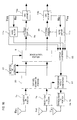
- Fig. 12 shows an example of the configuration of a receiver corresponding to the transmitter of Fig. 11 .
- down-conversion to the baseband is performed by the reception RF portions 7a, 7b, and the channel estimation portion 20 uses the pilot to perform channel estimation.
- propagation path compensation is performed, the modulated wave is demodulated by the demodulation portion 8, and data decoding is performed by the decoding portions 9a, 9b.
- the transmitter side notifies the receiver of the adaptive modulation format using a well-known method.
- Decoded data is subjected to CRC judgment by the CRC judgment portions 10a, 10b as error checking, and if there are no errors, (Yes) output is generated, but if there are errors (No) output is generated.
- a transmission weight suitable for retransmission is calculated by the transmission weight generation portion 21 from the channel estimation result by the channel estimation portion 20.
- the weight information calculated by the transmission weight generation portion 21 is included, and the control information up-converted by the transmission RF portions 6a, 6b and is fed back to the transmitting side.
- the transmission weight calculated by the transmission weight generation portion 21 is used to calculate the space for maximum transmission of energy, using for example the following equation.
- This matrix H is decomposed into a unitary matrix and a diagonal matrix using the SVD (Singular Value Decomposition) algorithm as follows.
- U U ⁇ ⁇ V H
- U is a unitary matrix (with N rows by N columns)
- ⁇ is a matrix (with N rows by M columns) having positive singular values ( ⁇ 1 , ⁇ 2 ... ⁇ M ) in diagonal elements
- V H is a unitary matrix (with M rows by M columns).
- the square of the positive values of the diagonal elements represent the radio propagation energy, and so the gain is maximized by performing beamforming toward the space ⁇ i ) in which the singular values are greatest.
- the transmission weight vector is represented by W tx
- the reception weight vector by W H rx . Because of energy normalization, the magnitudes of the elements of the vectors are the same, and moreover the following conditions apply.
- ⁇ i can be extracted as follows.
- Fig. 13 shows the configuration of the transmitter shown in Fig. 11 , having further features.
- the scheduler 1 When a NACK judgment has been given for previously transmitted symbols. the scheduler 1 is notified, a retransmission instruction is issued from the scheduler 1, and at the data readout instruction portion 14 the same data as before and new data for transmission are retrieved.
- the scheduler 1 specifies tot he encoding specification portion 121 the place in the stream for retransmission, and predetermined encoding is performed.
- Fig. 14 shows an example of the configuration of a receiver corresponding to the transmitter configuration of Fig. 13 .
- a change in Fig. 14 compared with the receiver configuration in Fig. 12 is the fact that there is no control signal for the transmission weight extraction portion 12 from an estimation value from the channel estimation portion 20.
- STBC STBC
- SFBC SFBC
- CDD Code Division Multiple Access
- SFBC is an extension of STBC.
- STBC is described for example in S. Vahid Tarokh et al, "Space-Time Block Codes from Orthogonal Designs", IEEE Trans. on Info. Theory, vol. 45 no. 5, July 1999 .
- CDD is described for example in A. Huebner et al, "A Simple Space-Frequency Coding Scheme with Cyclic Delay Diversity for OFDM", 2003.
- Fig. 15 shows an example of further extension of the transmitter configurations of Fig. 11 and Fig. 13 .
- a major feature is the presence of a transmission method decision portion 23.
- this transmission method decision portion 23 it is possible to choose between use of transmission diversity and use of beamforming for retransmission.
- a transmission diversity/beamforming specification portion 24 makes a specification corresponding to the retransmission mode decided by the transmission method decision portion 23, and a selection bit generated by a selection bit generation portion 25 corresponding to the specified transmission method is added as a control signal by addition circuits 26a, 26b to notify the receiving side.
- the specification portion 24 does not specify transmission diversity or beamforming, and in the selection bit generation portion 25 also a selection bit is not generated, and DTX (Discontinuous Transmission) transmission is performed.
- Fig. 16 is a receiving configuration corresponding to Fig. 15 , and has functions which are further extensions with respect to Fig. 12 and Fig. 14 .
- a major feature is the adaptive application of transmission diversity or beamforming by the transmission method decision portion 23 during retransmission by the transmitter, as explained above using Fig. 15 .
- the selection bit which was generated by the selection bit generation portion 25 and inserted by the addition circuits 26a, 26b on the transmission side is extracted.
- Fig. 17 shows an example of a frame format configuration used when performing adaptive modulation using the scheduler 1, for the transmitter and receiver configurations explained above.
- the pilot channel A, scheduler management channel B, and data channel are arranged in the time axis direction, and these respective channels are also multiplexed in the frequency axis direction.
- a selection bit D is used, inserting this into a portion of the scheduler management channel B and transmitting to the receiver side, as shown in Fig. 18 .
- the selection bit D information is judged when decoding the scheduler management channel, and by deciding the decoding method of the data channel sent next, data channel decoding is made possible.
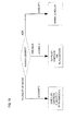
- Fig. 19 is a flow diagram showing the processing procedure of the scheduler 1 in the above receiver configuration example, and shows the flow of selecting a transmitter-side antenna.
- Fig. 20 shows the flow of scheduler operation to realize the configuration of Fig. 6 , for the case of retransmission data for one stream in the above judgment.
- step S11 all antennas are used in retransmission (step S11).
- step S12 readout from the retransmission stream data buffer 15 is performed (step S13).
- the read-out retransmission stream is subjected to the same adaptive modulation performed previously on the transmitted data (step S14).
- the retransmission stream is transmitted according to the previously decided transmission method, either transmission diversity or beamforming.
- Fig. 21 shows the flow of scheduler operation to realize the configuration of Fig. 7 , for the case in which the retransmission data comprises one stream.
- step S11A the number of antennas used in retransmission and the allocated antennas are decided.
- step S12 reading of the retransmission stream and a new stream from the data buffer 15 is performed (step S13A).
- the read-out retransmission stream is subjected to the same adaptive modulation performed previously on the transmitted data, and adaptive modulation of the new stream is also performed (step S14A).
- step S15 the previously decided transmission method is employed for the retransmission stream (step S15), which is transmitted (step S16).
- Fig. 22 shows the flow of scheduler operation to realize the configuration of Fig. 8 , for example, for a case comprising a plurality of retransmission streams.
- step S10 the order of the plurality of retransmission streams is decided.
- step S12 In parallel with operation to decide the retransmission method (step S12), readout of the retransmission streams from the data buffer 15 is performed (step S13).
- the read-out retransmission streams are subjected to the same adaptive modulation performed previously on the transmitted data (step S14).
- step S15 having been subjected to adaptive modulation, the previously decided transmission diversity or beamforming transmission method is employed for the retransmission streams (step S15), which are transmitted (step S16).
- step S17 The above processing is performed until the above-decided transmission stream order is completed (Yes in step S17), and upon completion, there is a transition to normal transmission (step S18).
- Fig. 23 shows the flow of scheduler operation to realize the configuration of Fig. 9 and Fig. 10 , for example, for a case comprising a plurality of retransmission streams.
- step S11B For each retransmission stream, the number of retransmission antennas and the allocated antennas are decided (step S11B). Applied to the configuration of Fig. 9 , a decision is made to allocate two transmission antennas Tx1 and Tx2 to stream d1, and two transmission antennas Tx3 and Tx4 to stream d2.
- Readout of the retransmission streams and the new streams is performed (step S13A), and at the same time the retransmission method is decided for each retransmission stream (step S12A).
- Adaptive modulation of each stream is performed (step S14B), and then the retransmission method previously decided corresponding to a retransmission stream is applied to the retransmission stream (step S15A), which is transmitted (step S16).
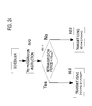
- Fig. 24 shows the flow of transmission method selection/judgment for a retransmission period, using as a criterion the fading speed.
- the retransmission period which is the difference between the time at which data was first sent and the retransmission time, and the fading speed Fd determined from the channel estimation value, are used to perform selection/judgment as to whether coding diversity or beamforming should be used as the retransmission method (step S21).
- the fading speed Fd is multiplied by an appropriate parameter ⁇ to set an appropriate threshold value.
- fading speed Fd a method used in the prior art may be employed.
- ⁇ the optimum value determined in computer simulations or similar may be employed.
- Fig. 25 shows a second transmission method selection/judgment flow for a retransmission period, using as a criterion the fading speed.
- a retransmission instruction is output from the scheduler (step S20)
- the eigenvalue of the channel correlation matrix is used to calculate the diversity dimension, and depending on how large this is compared with the correlation matrix maximum rank N (step S21A)
- the retransmission method is selected as using coding diversity or using beamforming.
- a diagonal matrix D having the eigenvalues can be extracted.
- the eigenvalues of the correlation matrix S are positive integers, and so the maximum value is selected as follows.
- ⁇ max arg max ⁇ 1 ⁇ 2 ... ⁇ N
- values are between 0 and 1.0, and an appropriate value optimized in computer simulations may be used.
- Fig. 26 shows a third transmission method selection/judgment flow for a retransmission period, using as a criterion the fading speed.
- step S21bn the feedback link SIR is compared with an appropriate threshold value TH (step S21bn), and if the SIR of the weight information used in transmission is higher than the threshold value TH and is reliable, beamforming is used (Yes in step S21B).
- threshold value TH an appropriate value optimized in computer simulations may be used.
Landscapes
- Engineering & Computer Science (AREA)
- Computer Networks & Wireless Communication (AREA)
- Signal Processing (AREA)
- Physics & Mathematics (AREA)
- Mathematical Physics (AREA)
- Quality & Reliability (AREA)
- Detection And Prevention Of Errors In Transmission (AREA)
- Radio Transmission System (AREA)
- Mobile Radio Communication Systems (AREA)
Abstract
Description
- The present invention relates to a data retransmission method, and to a radio communication system employing the same.
- In recent years, MIMO (Multi-Input Multi-Output) technology has been studied for application to mobile communication systems which are radio communication systems, as means of greatly improving communication throughput. Among such MIMO technologies, PARC (Per Antenna Rate Control) technology (Non-patent Reference 1), in which propagation quality between transmission and reception antennas is measured for each antenna corresponding to a plurality of segments, and adaptive modulation is performed according to the propagation quality of the transmission antenna to adaptively allocate transmission rates, is attracting attention.
- PARC technology handles transmission rates independently for each of multiple antennas, and with respect to retransmission as well, a Cyclic Redundancy Check (CRC) can be added at each transmission antenna and retransmission controlled independently to promote improvement of communication efficiency.
- In
Patent Reference 1, an invention is proposed relating to retransmission at the time of MIMO application enabling different transmission weighting from the initial transmission and obtaining of diversity gain. - Non-patent Reference 1: 3GPP TR25.876
- Patent Reference 1: Japanese Laid-open Patent Publication No.
2004-112098 - However, in the description of
Patent Reference 1, there is no discussion of PARC performing retransmission for each transmission stream, and there is inadequate discussion of retransmission methods when one stream or a plurality of streams are erroneous during transmission of a plurality of streams. - Hence an object of the present invention is to provide a data retransmission method capable of ensuring QoS (Quality of Service) for services for which retransmission delays cannot be allowed (multicast broadcasts, television conversations, games), as well as a radio communication system employing such a method.
- A first mode of a data retransmission method which attains this object of the present invention is a data retransmission method, in a radio communication system having a plurality of transmission systems corresponding to each antenna corresponding to a plurality of segments, in which adaptive modulation is performed according to the propagation quality of a transmission antenna, and a plurality of data streams are transmitted from the plurality of transmission systems, and is characterized in that when there is a transmission error in transmission data in any of the plurality of data streams, transmission data in which the transmission error occurred is simultaneously retransmitted by at least two transmission systems of the plurality of data streams.
- Additionally to the above characteristics, as a further detailed structure, the data retransmission method includes: deciding, when there is a transmission error in each of the transmission data of at least two data streams among the plurality of data streams, the order of retransmission of the transmission data with the transmission errors; and retransmitting the transmission data with the transmission errors, in the decided order, in use of two or more of the transmission systems.
- Alternatively, the data transmission method includes: deciding, when there is a transmission error in each of the transmission data of at least two data streams among the plurality of data streams, the order of retransmission of the transmission data with the transmission errors; and retransmitting the transmission data with the transmission errors, in the decided order, in use of two or more of the transmission systems.
- Through the above characteristics, when in this invention retransmission is performed under circumstances in which errors occur in a certain stream portion, by retransmitting the symbols of the stream in which the errors occurred to all antennas, the reoccurrence of errors during retransmission can be prevented, and QoS (Quality of Service) can be ensured for services (multicast broadcasts, television conversations, games). Hence through application of this invention, a data retransmission method with high throughput, and a mobile communication system employing this method, can be provided.
-
-
Fig. 1 illustrates the PARC concept. -
Fig. 2 shows the circumstances of a data series in a case in which the PARC concept explained usingFig. 1 is employed and there are no reception errors. -
Fig. 3 shows the circumstances of the time series of data when simultaneous errors occur. -
Fig. 4 shows a method is employed in which the streams sent during retransmission inFig. 3 are interchanged. -
Fig. 5 shows a method of conventional retransmission under circumstances in which an error occurs in a certain stream portion. -
Fig. 6 is a time series diagram showing an example of a data retransmission method according to this invention. -
Fig. 7 is a time series diagram showing an example of a retransmission method according to this invention, for a case in which there are a plurality of transmission antennas, greater in number than two. -
Fig. 8 shows an example of another retransmission method according to this invention. -
Fig. 9 is an example of extension of the embodiment ofFig. 8 . -
Fig. 10 is a further modified example ofFig. 9 ; at the time of retransmission, data may be combined in the same slot and transmitted. -
Fig. 11 shows an example of the configuration of a first transmitter according to the invention. -
Fig. 12 shows an example of the configuration of a receiver corresponding to the transmitter ofFig. 11 . -
Fig. 13 shows the configuration of the transmitter shown inFig. 11 , having further features. -
Fig. 14 shows an example of the configuration of a receiver corresponding to the transmitter configuration ofFig. 13 . -
Fig. 15 shows an example of further extension of the transmitter configurations ofFig. 11 andFig. 13 . -
Fig. 16 is a receiving configuration corresponding toFig. 15 . -
Fig. 17 shows an example of a frame format configuration used when performing adaptive modulation using the scheduler. -
Fig. 18 is a diagram for explaining an example where a selection bit D is inserted into a portion of the scheduler management channel B and is transmitted to the receiver side. -
Fig. 19 is a flow diagram showing the processing procedure of the scheduler in the above receiver configuration example, and shows the flow of selecting a transmitter-side antenna. -
Fig. 20 shows the flow of scheduler operation to realize the configuration ofFig. 6 , for the case of retransmission data for one stream. -
Fig. 21 shows the flow of scheduler operation to realize the configuration ofFig. 7 , for the case in which the retransmission data comprises one stream. -
Fig. 22 shows the flow of scheduler operation to realize the configuration ofFig. 8 , for example, for a case comprising a plurality of retransmission streams. -
Fig. 23 shows the flow of scheduler operation to realize the configuration ofFig. 9 and Fig. 10 , for example, for a case comprising a plurality of retransmission streams. -
Fig. 24 shows the flow of transmission method selection/judgment for a retransmission period, using as a criterion the fading speed. -
Fig. 25 shows a second transmission method selection/judgment flow for a retransmission period, using as a criterion the fading speed. -
Fig. 26 shows a third transmission method selection/judgment flow for a retransmission period, using as a criterion the fading speed. - Below, embodiments of the present invention; but to facilitate understanding of the invention, the PARC concept is first explained.
-
Fig. 1 illustrates the PARC concept. InFig. 1 , MIMO multiplexing to transmit the data of two different data streams d1 and d2 to be transmitted is shown. - Control is performed by the AMC (Adaptive Modulation and Coding scheme)
control portion 2 to subject each of these data streams d1, d2 to appropriate error encoding and modulation in theerror encoding circuits adaptive modulation circuits scheduler 1, and the transmission rate of each of the streams is specified. - When transmitting streams to each of the transmission antennas Tx1 and Tx2, the data streams d1 and d2 are passed through without special processing by the
weighting portion 5, and are up-converted to the RF band by the transmission RF (Radio Frequency)portions - Here, adaptive modulation is not performed only for each transmission antenna; PARC also includes cases in which adaptive modulation is performed for each beam when weighting is performed by the
weighting portion 5 and transmission beams are generated. For this reason, theweighting portion 5 is shown inFig. 1 . - Signals which have passed through the
radio propagation path 10 arrive at the reception antennas Rx1 and Rx2, are down-converted to the baseband (BB) by thereception RF portions demodulation portion 8, and are decoded by thedecoding portions - Decoded data is subjected to a cyclic redundancy check (CRC) for errors by the CRC
judgment portions - An ACK or NACK signal is returned to the transmission source according to the CRC judgment result.
- When the CRC judgment result indicates an error, a NACK signal is generated by the retransmission request (HARQ: Hybrid Automatic Repeat reQuest)
portions decoding portions -
Fig. 2 shows the circumstances of a data series in a case in which the PARC concept explained usingFig. 1 is employed and there are no reception errors, and shows the manner in which data streams are sent as data series under PARC control. - The expression d1(n) represents the data of symbol n in the stream d1 transmitted from the transmission antenna Tx1. Similarly, the expression d2(n) represents the data of symbol n in the stream d2 transmitted from the transmission antenna Tx2. If there are no errors, new symbols continue to be transmitted one after another in each of these streams.
-
Fig. 3 shows the circumstances of the time series of data when simultaneous errors occur; a case is shown in which errors have occurred in all different streams under PARC control, or in which errors have occurred in MIMO multiplexing without performing CRC judgment for each stream. -
Fig. 3 shows an example in which the previous frame (d1(1), d2(1)) was erroneous, and so in the next frame the same information is retransmitted. - A SW (Stop and Wait) configuration in which confirmation that the data of the previous frame has arrived before transmitting the next data, or, a GBN (Go Back N) or SR (Selective Repeat) or other method, in which the next data is sent without waiting for confirmation, and retransmission is performed when an error occurs, can be employed.
- Also, in order to obtain retransmission gain, the previously described HARQ (Hybrid Automatic Repeat reQuest) can be employed.
- In the time series shown in
Fig. 4 , a method is employed in which the streams sent during retransmission inFig. 3 are interchanged; this is the example of the prior art described inPatent Reference 1 described above. That is, the data d1(1) transmitted from antenna Tx1 is retransmitted from antenna Tx2, and the data d2(1) transmitted from antenna Tx2 is retransmitted from antenna Tx1. By this means, spatial diversity gain can be obtained in retransmission for streams with considerable degradation. - The above has described a case in which errors occur in all different streams under PARC control, or errors occur in MIMO multiplexing in which CRC judgments are not performed for each stream.
- In contrast, there is the conventional method in which a stream in which an error has occurred is retransmitted, and new symbols in streams without errors continue to be transmitted one after another.
- That is,
Fig. 5 shows a method of conventional retransmission under circumstances in which an error occurs in a certain stream portion, in which the stream d1 in which the error has occurred is retransmitted, and new symbols in a stream d2 in which an error has not occurred continue to be sent one after another. - In these methods of the prior art, when an error again occurs at the time of retransmission, retransmission is repeated, a retransmission delay occurs, and due to this retransmission delay throughput declines when providing multicast broadcasts, television conversations, games, and other services, and there is the problem that the QoS can no longer be ensured.
- Hence in this invention, by providing a data retransmission method which results this problem, a method of this invention is a method in which, when retransmitting under circumstances in which an error has occurred in a certain stream portion, symbols of the stream in which the error occurred are transmitted by all the antennas.
-
Fig. 6 is a time series diagram showing an example of a data retransmission method according to this invention. In this example, when retransmitting under circumstances in which an error has occurred in a certain portion of the stream d1, the symbols of the stream in which the error occurred are transmitted by all antennas. - That is, in
Fig. 6 there are two transmission systems, and when an error has occurred in symbol d1(1) in stream d1 transmitted by the first transmission system, the same symbol d1(1) is transmitted from the transmission antennas Tx1 and Tx2 of the two transmission systems. - In this case, transmission diversity technologies such as STBC (Space Time Block Coding), STFC (Space Time Frequency Coding), CDD (Cyclic Delay Diversity), and similar, that is, space coding diversity in which signal points are arranged at each time and at each antenna, are applied, or beamforming technology is applied to obtain a gain, so that errors in retransmission can be greatly reduced.
-
Fig. 7 is a time series diagram showing an example of a retransmission method according to this invention, for a case in which there are a plurality of transmission antennas, greater in number than two, corresponding to transmission systems greater in number than two. - In
Fig. 7 , in a case in which an error occurs in symbol d1(1) in a portion of the data stream d1, three transmission antennas Tx1, Tx2, and Tx3 are shown as an example. - In this invention, rather than using all the antennas Tx1, Tx2, Tx3 to retransmit the symbol d1(1) of the stream in which the error occurred, some of the plurality of antennas (for example, antennas Tx1 and Tx2) are used to retransmit the symbol d1(1) of the stream with the error, to reduce errors in retransmission. By this means, the necessary retransmission gain is adjusted, and the decline in throughput can be held to a minimum.
-
Fig. 8 shows an example of another retransmission method according to this invention, and is an example in which errors have occurred simultaneously in a plurality of streams d1 and d2. - That is, in
Fig. 8 , circumstances are shown in which errors have occurred simultaneously at symbols d1(1) and d2(1) in streams d1 and d2. In order to obtain higher gain in retransmission, in this method the symbols d1(1) and d2(1) of the streams with errors are retransmitted using all the antennas Tx1 and Tx2. - That is, because there are a plurality of streams with errors (in the example of
Fig. 8 , two), retransmission is performed a plurality of times (two times), applying transmission diversity or beamforming. -
Fig. 9 is an example of extension of the embodiment ofFig. 8 . This is an example of a case in which errors have occurred simultaneously in the symbols d1(1) and d2(1) in the streams d1 and d2 corresponding to the plurality of antennas Tx1 and Tx2, and there exist a plurality of other antennas Tx3 and Tx4 as well. - In the example shown in
Fig. 9 , transmission diversity or beamforming is applied in retransmission of the symbol d1(1) by the antennas Tx1 and Tx2. At the same time, transmission diversity or beamforming is applied in retransmission of the symbol d2(1) by the plurality of other antennas Tx3 and Tx4. - By this means, errors in retransmitting the symbols with errors d1(1) and d2(1) in the streams d1 and d2 can be reduced.
-
Fig. 10 is a further modified example ofFig. 9 ; at the time of retransmission, data may be combined in the same slot and transmitted. - For example, beamforming is performed using different weights for a plurality of retransmission streams d1(1) and d2(1), and orthogonal space is used in the retransmission. In the case of combination of transmission antennas in
Fig. 10 , where retransmission beamforming is performed, there must be feedback of the set of weights for the number of retransmission streams. - Next, an example of the configuration of a transmitter and receiver which realize the data retransmission method of this invention described above, as well as operation thereof, are explained.
-
Fig. 11 shows an example of the configuration of a first transmitter according to the invention. In particular, the configuration shown inFig. 11 is the configuration of a transmitter which uses beamforming in performing retransmission. - First, feedback signals received by the reception antennas Rx1 and Rx2 are converted to the baseband by the
reception RF portions demodulation portion 8, and are decoded by thedecoding portion 9. Based on the decoding result of thedecoding portion 9, the ACK/NACK judgment portion 11 judges whether the previously transmitted symbols were correctly decoded on the receiver side. - When decoding is performed correctly on the receiver side, that is, in the case of an ACK response, the
scheduler 1 is notified of sending of the next new data. On the other hand, when decoding could not be performed correctly on the receiver side, that is, in the case of a NACK response, thescheduler 1 is notified of retransmission, and at the same time the weight used in retransmission is extracted by a transmissionweight extraction portion 12 for each transmission antenna. - When an ACK response is received and ordinary data transmission is performed, the
scheduler 1 notifies a datareadout instruction portion 14 and the transmissionweight extraction portion 12 of the timing and adaptive modulation information for sending the data. As a result, the state of the start of data transmission is entered. - The data
readout instruction portion 14 retrieves data accumulated in thedata buffer 15 in amounts that can be transmitted in each stream, theerror encoding circuits AMC control portion 2 controls themodulation circuits scheduler 1. Further, the modulated signals are input to theweighting portion 5. - This invention can be implemented whether weights are or are not added, setting the transmission direction, in the
weighting portion 5 according to the MIMO multiplexing method. The output of theweighting portion 5 is up-converted by thetransmission RF portions - On the other hand, in data retransmission after receiving a NACK response, when implementing this invention a retransmission instruction is issued from the
scheduler 1, and the same data as in the previous transmission and new data for transmission are retrieved from thedata buffer 15 by the datareadout instruction portion 14. - With respect to this data retrieval, as described in
Fig. 6 through Fig. 10 explained above, retrieval is performed for the number of streams transmitted with a certain timing. - Next, the
encoding circuits AMC control portion 2 conforming to thescheduler 1, new streams are adaptively modulated by themodulation portions weighting portion 5, thescheduler 1 instructs use of the weight which has been fed back from the receiver side for a retransmission stream. - With respect to a newly transmitted stream, a weight may or may not be added. Data comprising retransmission streams is up-converted by the
transmission RF portions -
Fig. 12 shows an example of the configuration of a receiver corresponding to the transmitter ofFig. 11 . - First, down-conversion to the baseband is performed by the
reception RF portions channel estimation portion 20 uses the pilot to perform channel estimation. Using this channel estimation value, propagation path compensation is performed, the modulated wave is demodulated by thedemodulation portion 8, and data decoding is performed by thedecoding portions - In demodulation and decoding, the transmitter side notifies the receiver of the adaptive modulation format using a well-known method. Decoded data is subjected to CRC judgment by the
CRC judgment portions - When there is (No) output, data prior to decoding is stored in the
HARQ buffers NACK conversion portion 22. - Here, when there is a NACK response, a transmission weight suitable for retransmission is calculated by the transmission
weight generation portion 21 from the channel estimation result by thechannel estimation portion 20. - And, in addition to ACK/NACK, the weight information calculated by the transmission
weight generation portion 21 is included, and the control information up-converted by thetransmission RF portions - Here, the transmission weight calculated by the transmission
weight generation portion 21 is used to calculate the space for maximum transmission of energy, using for example the following equation. - That is, let the channel estimation values when transmission is by M antennas and reception is by N antennas form a matrix H (of N rows by M columns).
- This matrix H is decomposed into a unitary matrix and a diagonal matrix using the SVD (Singular Value Decomposition) algorithm as follows.
-

- The square of the positive values of the diagonal elements represent the radio propagation energy, and so the gain is maximized by performing beamforming toward the space λi) in which the singular values are greatest.
- Here, the transmission weight vector is represented by Wtx, and the reception weight vector by WH rx. Because of energy normalization, the magnitudes of the elements of the vectors are the same, and moreover the following conditions apply.
-

-

- Using these weights, λi can be extracted as follows.
-

-
Fig. 13 shows the configuration of the transmitter shown inFig. 11 , having further features. - That is, in this configuration the transmission
weight extraction portion 12 inFig. 11 is replaced with anencoding specification portion 121. - When a NACK judgment has been given for previously transmitted symbols. the
scheduler 1 is notified, a retransmission instruction is issued from thescheduler 1, and at the datareadout instruction portion 14 the same data as before and new data for transmission are retrieved. Here, thescheduler 1 specifies tot he encodingspecification portion 121 the place in the stream for retransmission, and predetermined encoding is performed. -
Fig. 14 shows an example of the configuration of a receiver corresponding to the transmitter configuration ofFig. 13 . - A change in
Fig. 14 compared with the receiver configuration inFig. 12 is the fact that there is no control signal for the transmissionweight extraction portion 12 from an estimation value from thechannel estimation portion 20. - By employing open-loop control, there are the advantages that control information feedback is reduced and reverse-link throughput characteristics are not degraded.
- STBC, SFBC, CDD, or similar are conceivable as the encoded transmission used here. SFBC is an extension of STBC.
- STBC is described for example in S. Vahid Tarokh et al, "Space-Time Block Codes from Orthogonal Designs", IEEE Trans. on Info. Theory, vol. 45 no. 5, July 1999. And, CDD is described for example in A. Huebner et al, "A Simple Space-Frequency Coding Scheme with Cyclic Delay Diversity for OFDM", 2003.
-
Fig. 15 shows an example of further extension of the transmitter configurations ofFig. 11 andFig. 13 . A major feature is the presence of a transmission method decision portion 23. In this configuration, by means of this transmission method decision portion 23 it is possible to choose between use of transmission diversity and use of beamforming for retransmission. - Also, when on the receiver side it is not possible to judge which has been selected, a transmission diversity/
beamforming specification portion 24 makes a specification corresponding to the retransmission mode decided by the transmission method decision portion 23, and a selection bit generated by a selectionbit generation portion 25 corresponding to the specified transmission method is added as a control signal byaddition circuits - After all the previously transmitted symbols is judged as ACK, the
specification portion 24 does not specify transmission diversity or beamforming, and in the selectionbit generation portion 25 also a selection bit is not generated, and DTX (Discontinuous Transmission) transmission is performed. - On the transmitter side, because beamforming operates under closed-loop control, the judgment of whether to perform beamforming transmission or to use transmission diversity is made based for example on whether fading fluctuations are being followed.
-
Fig. 16 is a receiving configuration corresponding toFig. 15 , and has functions which are further extensions with respect toFig. 12 andFig. 14 . - A major feature is the adaptive application of transmission diversity or beamforming by the transmission method decision portion 23 during retransmission by the transmitter, as explained above using
Fig. 15 . Hence on the receiver side, in the selectionbit extraction portion 27 after channel estimation by thechannel estimation portion 20, the selection bit which was generated by the selectionbit generation portion 25 and inserted by theaddition circuits - Then, in the
demodulation portion 8 and thedecoding portions -
Fig. 17 shows an example of a frame format configuration used when performing adaptive modulation using thescheduler 1, for the transmitter and receiver configurations explained above. - The pilot channel A, scheduler management channel B, and data channel are arranged in the time axis direction, and these respective channels are also multiplexed in the frequency axis direction.
- Transmission over the pilot channel A is performed, propagation path fluctuation is estimated, and this is used to decipher information in the scheduler management channel B and read the written user allocation information and adaptive modulation information; using this propagation path estimation value and adaptive modulation information, a data channel addressed to the terminal itself is decoded.
- As explained in
Fig. 15 andFig. 16 , when switching between transmission encoding diversity and beamforming, the receiving side must know the transmission method used prior to demodulation. For this reason a selection bit D is used, inserting this into a portion of the scheduler management channel B and transmitting to the receiver side, as shown inFig. 18 . - On the receiver side, the selection bit D information is judged when decoding the scheduler management channel, and by deciding the decoding method of the data channel sent next, data channel decoding is made possible.
-
Fig. 19 is a flow diagram showing the processing procedure of thescheduler 1 in the above receiver configuration example, and shows the flow of selecting a transmitter-side antenna. - In
Fig. 19 , based on the judgment result of the ACK/NACK judgment portion 11, the scheduler to be used is decided. - That is, in ACK/NACK judgment, when the result is ACK (judgment A) the normal scheduler is selected, but when the result is NACK for one stream, the scheduler comprising one retransmission (judgment B) is selected, and when the result is NACK for a plurality of streams (judgment C), the scheduler comprising a plurality of retransmissions is selected.
-
Fig. 20 shows the flow of scheduler operation to realize the configuration ofFig. 6 , for the case of retransmission data for one stream in the above judgment. - In this case, all antennas are used in retransmission (step S11). In parallel with operation to decide the retransmission method (step S12), readout from the retransmission
stream data buffer 15 is performed (step S13). The read-out retransmission stream is subjected to the same adaptive modulation performed previously on the transmitted data (step S14). - Then, having been subjected to adaptive modulation, the retransmission stream is transmitted according to the previously decided transmission method, either transmission diversity or beamforming.
-
Fig. 21 shows the flow of scheduler operation to realize the configuration ofFig. 7 , for the case in which the retransmission data comprises one stream. - In this case, the number of antennas used in retransmission and the allocated antennas are decided (step S11A). In parallel with operation to decide the retransmission method (step S12), reading of the retransmission stream and a new stream from the
data buffer 15 is performed (step S13A). - The read-out retransmission stream is subjected to the same adaptive modulation performed previously on the transmitted data, and adaptive modulation of the new stream is also performed (step S14A).
- Then, having been subjected to adaptive modulation, the previously decided transmission method is employed for the retransmission stream (step S15), which is transmitted (step S16).
-
Fig. 22 shows the flow of scheduler operation to realize the configuration ofFig. 8 , for example, for a case comprising a plurality of retransmission streams. - First, the order of the plurality of retransmission streams is decided (step S10).
- Settings are made such that all the antennas are used in retransmission (step S11).
- In parallel with operation to decide the retransmission method (step S12), readout of the retransmission streams from the
data buffer 15 is performed (step S13). The read-out retransmission streams are subjected to the same adaptive modulation performed previously on the transmitted data (step S14). - Then, having been subjected to adaptive modulation, the previously decided transmission diversity or beamforming transmission method is employed for the retransmission streams (step S15), which are transmitted (step S16).
- The above processing is performed until the above-decided transmission stream order is completed (Yes in step S17), and upon completion, there is a transition to normal transmission (step S18).
-
Fig. 23 shows the flow of scheduler operation to realize the configuration ofFig. 9 and Fig. 10 , for example, for a case comprising a plurality of retransmission streams. - For each retransmission stream, the number of retransmission antennas and the allocated antennas are decided (step S11B). Applied to the configuration of
Fig. 9 , a decision is made to allocate two transmission antennas Tx1 and Tx2 to stream d1, and two transmission antennas Tx3 and Tx4 to stream d2. - Readout of the retransmission streams and the new streams is performed (step S13A), and at the same time the retransmission method is decided for each retransmission stream (step S12A). Adaptive modulation of each stream is performed (step S14B), and then the retransmission method previously decided corresponding to a retransmission stream is applied to the retransmission stream (step S15A), which is transmitted (step S16).
- Next, an example of an algorithm for selection criterion conditions is explained below, for cases in which coding diversity and beamforming can be adaptively selected as the previously explained transmission methods.
-
Fig. 24 shows the flow of transmission method selection/judgment for a retransmission period, using as a criterion the fading speed. - When a retransmission instruction is issued by the scheduler 1 (step S20), the retransmission period, which is the difference between the time at which data was first sent and the retransmission time, and the fading speed Fd determined from the channel estimation value, are used to perform selection/judgment as to whether coding diversity or beamforming should be used as the retransmission method (step S21).
- The fading speed Fd is multiplied by an appropriate parameter α to set an appropriate threshold value.
- That is, when the retransmission period Fd is smaller than a prescribed fading speed Fd (= Fd×α), the coding diversity transmission method is selected (step S22). Conversely, when the retransmission period Fd is larger than the prescribed fading speed Fd (= Fd×α), the beamforming transmission method is selected (step S23).
- An important point in this judgment method is that, when data is initially sent, the pilot channel is used to generate a propagation path estimation and beamforming weight, and the fading speed Fd is used to judge whether at the time of retransmission the propagation path has greatly changed. And, when the propagation path has not greatly changed, beamforming is employed.
- With respect to the fading speed Fd, a method used in the prior art may be employed. With respect to α, the optimum value determined in computer simulations or similar may be employed.
-
Fig. 25 shows a second transmission method selection/judgment flow for a retransmission period, using as a criterion the fading speed. InFig. 25 , when a retransmission instruction is output from the scheduler (step S20), the eigenvalue of the channel correlation matrix is used to calculate the diversity dimension, and depending on how large this is compared with the correlation matrix maximum rank N (step S21A), the retransmission method is selected as using coding diversity or using beamforming. - With respect to the channel matrix, the channel estimation value H to receive feedback signals over a feedback link is employed to determine the channel correlation matrix S = HHH. Through eigenvalue expansion of this matrix, a diagonal matrix D having the eigenvalues can be extracted.
-

- The eigenvalues of the correlation matrix S are positive integers, and so the maximum value is selected as follows.
-

- An important point of this judgment method is the fact that the eigenvalues of the correlation matrix S and the maximum value thereof are used to evaluate energy variation in the eigenspace of the propagation path, and if there is a certain amount of variation, use of coding diversity is selected.
- With respect to β, values are between 0 and 1.0, and an appropriate value optimized in computer simulations may be used.
- This eigenvalue analysis is described in detail in Simon Haykin, "Adaptive Filter Theory 4th Edit".
-
Fig. 26 shows a third transmission method selection/judgment flow for a retransmission period, using as a criterion the fading speed. When a retransmission instruction is output from the scheduler (step S20), the SIR obtained by employing the channel estimation value used to receive feedback signals over the feedback link is used to select the retransmission method as using coding diversity or using beamforming. - An important point of this method is that the feedback link SIR is compared with an appropriate threshold value TH (step S21bn), and if the SIR of the weight information used in transmission is higher than the threshold value TH and is reliable, beamforming is used (Yes in step S21B).
- With respect to the threshold value TH, an appropriate value optimized in computer simulations may be used.
- By means of the above-described invention, the reoccurrence of errors in retransmission can be prevented, and QoS (Quality of Service) can be ensured for services multicast broadcasts, television conversations, games). Hence through application of this invention, a high-throughput data retransmission method and a mobile communication system employing this method can be provided, and can contribute greatly to industry.
Claims (12)
- A data retransmission method for a radio communication system in which a plurality of data streams are transmitted from a plurality of transmission systems, the method comprising:simultaneously retransmitting, when there is a transmission error in the transmission data in any of the plurality of data streams, the transmission data with the transmission error by using at least two transmission systems of the plurality of data streams.
- The data retransmission method according to Claim 1, comprising: deciding, when there is a transmission error in each of the transmission data of at least two data streams among the plurality of data streams, the order of retransmission of the transmission data with the transmission errors; and retransmitting the transmission data with the transmission errors, in the decided order, in use of two or more of the transmission systems.
- The data retransmission method according to Claim 1, comprising: retransmitting, when there is a transmission error in each of the transmission data of at least two data streams among the plurality of data streams, the transmission data with the transmission errors simultaneously from at least two transmission systems of the plurality of data streams, respectively corresponding to the transmission data with the transmission errors.
- The data retransmission method according to any of Claims 1 through 3, further comprising: performing beamforming in retransmission of the transmission data with transmission errors and performing retransmission.
- The data retransmission method according to any of Claims 1 through 3, further comprising: performing spatial coding in retransmission of the transmission data with transmission errors and performing retransmission.
- The data retransmission method according to any of Claims 1 through 3, further comprising:adaptively selecting beamforming or spatial coding in retransmission of the transmission data with transmission errors and performing retransmission;employing as a criterion for adaptive selection of the beamforming or spatial coding comparison of the transmission period and a prescribed fading speed; andselecting, when the retransmission period is smaller than the prescribed fading speed, the beamforming, but selecting, when the retransmission period is smaller than the prescribed fading speed, the spatial coding.
- The data retransmission method according to any of Claims 1 through 3, further comprising:adaptively selecting beamforming or spatial coding in retransmission of the transmission data with transmission errors and performing retransmission;employing as a criterion for adaptive selection of the beamforming or spatial coding calculation of the diversity dimension in use of eigenvalues of the channel correlation matrix;comparing the calculated diversity dimension with the correlation matrix maximum rank N; andemploying, when the calculated diversity dimension has a prescribed magnitude with respect to the correlation matrix maximum rank N, spatial coding, and selecting, when the calculated diversity dimension does not have the prescribed magnitude, beamforming.
- The data retransmission method according to any of Claims 1 through 3, further comprising:adaptively selecting beamforming or spatial coding in retransmission of the transmission data with transmission errors and performing retransmission;employing as a criterion for adaptive selection of the beamforming or spatial coding comparison of the signal-to-noise ratio (SIR) with a prescribed threshold value; andselecting, when the signal-to-noise ratio (SIR) is larger than a prescribed threshold value, the beamforming, and selecting, when the signal-to-noise ratio SIR) is not larger than the prescribed threshold value, the spatial coding.
- A radio communication system, wherein a plurality of transmission systems each comprise a modulator for which a modulation method is adaptively selected and controlled, and a radio transmission portion which converts the output of the modulator to a radio frequency,
a scheduler, which controls the modulator so as to perform adaptive modulation according to the propagation path quality, is further provided;
when there is a transmission error in the transmission data in any of the plurality of data streams transmitted by the plurality of transmission systems, control is executed by the scheduler to read out data from a data buffer so that the transmission data with the transmission error is retransmitted simultaneously in use of at least two transmission systems of the plurality of data streams; and
the modulator is controlled such that the data to be retransmitted undergoes the same adaptive modulation as in the previous transmission. - The radio communication system according to Claim 9, further comprising a weighting portion in each of the plurality of transmission systems between the modulator and radio transmission portion, wherein
the scheduler controls weights with timing to transmit at least the retransmission data corresponding to transmission weights received in notification by the weighting portion from the receiving side. - The radio communication system according to Claim 9, further comprising an encoding portion in each of the plurality of transmission systems between the modulator and radio transmission portion, wherein when the transmission data has a reception error, at the time of retransmission of the transmission data, control is executed by the scheduler to perform prescribed encoding in the encoding portion.
- The radio communication system according to Claim 9, comprising a weighting portion, an encoding portion, and a transmission method decision portion in each of the plurality of transmission systems between the modulator and radio transmission portion, wherein
when there is an error on the receiving side in the previous transmission data, the transmission method decision portion decides on a transition method deciding whether to execute control of weighting by the weighting portion at the time of retransmission of the transmission data or to execute control to perform prescribed coding in the encoding portion, and
a bit identifying the decided transmission method is transmitted to the receiving side at the time of retransmission of the transmission data.
Priority Applications (1)
| Application Number | Priority Date | Filing Date | Title |
|---|---|---|---|
| EP13196162.5A EP2765714A3 (en) | 2007-05-21 | 2007-05-21 | Data retransmission method and radio communication system using same |
Applications Claiming Priority (1)
| Application Number | Priority Date | Filing Date | Title |
|---|---|---|---|
| PCT/JP2007/000539 WO2008142733A1 (en) | 2007-05-21 | 2007-05-21 | Data retransmission method and radio communication system adopting same |
Related Child Applications (1)
| Application Number | Title | Priority Date | Filing Date |
|---|---|---|---|
| EP13196162.5A Division EP2765714A3 (en) | 2007-05-21 | 2007-05-21 | Data retransmission method and radio communication system using same |
Publications (2)
| Publication Number | Publication Date |
|---|---|
| EP2157708A1 true EP2157708A1 (en) | 2010-02-24 |
| EP2157708A4 EP2157708A4 (en) | 2013-10-23 |
Family
ID=40031460
Family Applications (2)
| Application Number | Title | Priority Date | Filing Date |
|---|---|---|---|
| EP07737195.3A Withdrawn EP2157708A4 (en) | 2007-05-21 | 2007-05-21 | DATA RETRANSMISSION METHOD AND RADIO COMMUNICATION SYSTEM ADOPTING SUCH METHOD |
| EP13196162.5A Withdrawn EP2765714A3 (en) | 2007-05-21 | 2007-05-21 | Data retransmission method and radio communication system using same |
Family Applications After (1)
| Application Number | Title | Priority Date | Filing Date |
|---|---|---|---|
| EP13196162.5A Withdrawn EP2765714A3 (en) | 2007-05-21 | 2007-05-21 | Data retransmission method and radio communication system using same |
Country Status (4)
| Country | Link |
|---|---|
| US (1) | US8341483B2 (en) |
| EP (2) | EP2157708A4 (en) |
| JP (1) | JP5035338B2 (en) |
| WO (1) | WO2008142733A1 (en) |
Cited By (1)
| Publication number | Priority date | Publication date | Assignee | Title |
|---|---|---|---|---|
| EP3446423A1 (en) * | 2016-04-19 | 2019-02-27 | Telefonaktiebolaget LM Ericsson (PUBL) | Applying more robust transmission procedure |
Families Citing this family (9)
| Publication number | Priority date | Publication date | Assignee | Title |
|---|---|---|---|---|
| KR100908064B1 (en) * | 2008-01-30 | 2009-07-15 | 엘지전자 주식회사 | Downlink control information delivery method |
| KR101399783B1 (en) * | 2008-03-20 | 2014-05-27 | 삼성전자주식회사 | Method and apparutus for retrnansmission mode selection in a mimo communication system |
| JP5150530B2 (en) * | 2009-03-03 | 2013-02-20 | 株式会社エヌ・ティ・ティ・ドコモ | Radio base station apparatus and radio communication method |
| JP2012222519A (en) * | 2011-04-06 | 2012-11-12 | Kyocera Corp | Radio communication device and retransmission control method |
| JP5673388B2 (en) * | 2011-06-23 | 2015-02-18 | 富士通株式会社 | Wireless device and wireless communication control program |
| EP2869490B1 (en) * | 2012-08-02 | 2022-01-19 | Huawei Technologies Co., Ltd. | Data retransmission method, device and system |
| JP6668686B2 (en) * | 2015-11-02 | 2020-03-18 | ソニー株式会社 | Transmission device |
| CN110352574B (en) * | 2017-03-01 | 2022-06-03 | 瑞典爱立信有限公司 | Improved acknowledgement signalling |
| WO2021084693A1 (en) * | 2019-10-31 | 2021-05-06 | 三菱電機株式会社 | Transmission device, reception device, communication system, control circuit, storage medium, and communication method |
Family Cites Families (21)
| Publication number | Priority date | Publication date | Assignee | Title |
|---|---|---|---|---|
| US7031419B2 (en) * | 2001-06-29 | 2006-04-18 | Nokia Corporation | Data transmission method and system |
| JP2004040232A (en) * | 2002-06-28 | 2004-02-05 | Matsushita Electric Ind Co Ltd | Wireless communication system, wireless transmitting device, and wireless receiving device |
| JP3679075B2 (en) | 2002-09-13 | 2005-08-03 | 松下電器産業株式会社 | Radio transmission apparatus and radio transmission method |
| US7391755B2 (en) * | 2002-09-30 | 2008-06-24 | Lucent Technologies Inc. | Signaling and control mechanisms in MIMO harq schemes for wireless communication systems |
| US7646744B2 (en) * | 2003-04-07 | 2010-01-12 | Shaolin Li | Method of operating multi-antenna wireless data processing system |
| CA2701501C (en) * | 2003-06-18 | 2016-01-26 | Nippon Telegraph And Telephone Corporation | Wireless packet communication method |
| EP1615365A4 (en) * | 2003-06-30 | 2011-05-11 | Fujitsu Ltd | MULTI-INPUT AND MULTI-OUTPUT TRANSMISSION SYSTEM |
| US8705659B2 (en) * | 2003-11-06 | 2014-04-22 | Apple Inc. | Communication channel optimization systems and methods in multi-user communication systems |
| WO2006057195A1 (en) * | 2004-11-25 | 2006-06-01 | Matsushita Electric Industrial Co., Ltd. | Multi-antenna transmitting apparatus, multi-antenna receiving apparatus, and data re-transmitting method |
| JP2006165970A (en) * | 2004-12-07 | 2006-06-22 | Sanyo Electric Co Ltd | Retransmission method and transmitting device, and receiving device using the same |
| JP4464836B2 (en) * | 2005-01-14 | 2010-05-19 | パナソニック株式会社 | Communication method for multi-antenna communication apparatus and multi-antenna communication apparatus |
| EP1843502A4 (en) * | 2005-01-25 | 2012-05-23 | Panasonic Corp | TRANSMISSION DEVICE AND TRANSMISSION METHOD |
| JP4599228B2 (en) * | 2005-05-30 | 2010-12-15 | 株式会社日立製作所 | Wireless transceiver |
| JP2007074171A (en) * | 2005-09-05 | 2007-03-22 | Matsushita Electric Ind Co Ltd | Wireless transmission device, wireless reception device, and methods thereof |
| JP4752602B2 (en) * | 2006-05-15 | 2011-08-17 | 株式会社日立製作所 | MIMO radio communication method and MIMO radio communication apparatus |
| EP1901496B1 (en) * | 2006-09-12 | 2010-09-01 | Panasonic Corporation | Link adaptation dependent on control signaling |
| US20090135944A1 (en) * | 2006-10-23 | 2009-05-28 | Dyer Justin S | Cooperative-MIMO Communications |
| US8121211B2 (en) * | 2007-03-26 | 2012-02-21 | Cisco Technology, Inc. | Adaptive switching techniques for hybrid automatic repeat request systems |
| US8250425B2 (en) * | 2008-08-15 | 2012-08-21 | Apple Inc. | Management of ARQ detection threshold in communication networks |
| WO2010062051A2 (en) * | 2008-11-02 | 2010-06-03 | 엘지전자 주식회사 | Pre-coding method for spatial multiplexing in multiple input and output system |
| US8320273B2 (en) * | 2010-03-30 | 2012-11-27 | Cisco Technology, Inc. | Link adaptation for retransmission schemes |
-
2007
- 2007-05-21 EP EP07737195.3A patent/EP2157708A4/en not_active Withdrawn
- 2007-05-21 JP JP2009515005A patent/JP5035338B2/en not_active Expired - Fee Related
- 2007-05-21 WO PCT/JP2007/000539 patent/WO2008142733A1/en not_active Ceased
- 2007-05-21 EP EP13196162.5A patent/EP2765714A3/en not_active Withdrawn
-
2009
- 2009-11-10 US US12/615,478 patent/US8341483B2/en not_active Expired - Fee Related
Cited By (1)
| Publication number | Priority date | Publication date | Assignee | Title |
|---|---|---|---|---|
| EP3446423A1 (en) * | 2016-04-19 | 2019-02-27 | Telefonaktiebolaget LM Ericsson (PUBL) | Applying more robust transmission procedure |
Also Published As
| Publication number | Publication date |
|---|---|
| WO2008142733A1 (en) | 2008-11-27 |
| EP2765714A3 (en) | 2014-12-24 |
| US20100058137A1 (en) | 2010-03-04 |
| EP2765714A2 (en) | 2014-08-13 |
| JPWO2008142733A1 (en) | 2010-08-05 |
| EP2157708A4 (en) | 2013-10-23 |
| JP5035338B2 (en) | 2012-09-26 |
| US8341483B2 (en) | 2012-12-25 |
Similar Documents
| Publication | Publication Date | Title |
|---|---|---|
| US8341483B2 (en) | Data retransmission method and radio communication system using the same | |
| EP1983781B1 (en) | Wireless communication system using multiantenna transmission technique | |
| US7684527B2 (en) | Communication device and communication method | |
| KR101542384B1 (en) | PMI selection method for non-adaptive HARQ in wireless communication systems supporting multiple antennas | |
| EP1376895B1 (en) | Apparatus and method for transmitting data using transmit antenna diversity in a packet service communication system | |
| EP1505741B1 (en) | Method and apparatus for scheduling multiple users in a mobile communication system using multiple transmit/receive antennas | |
| US8705659B2 (en) | Communication channel optimization systems and methods in multi-user communication systems | |
| US8577303B2 (en) | Apparatus and method for transmitting channel sounding signal in wireless communication system | |
| JP5069083B2 (en) | User apparatus, base station apparatus, and MIMO transmission control method | |
| US9209940B2 (en) | Method of retransmission for supporting MIMO in synchronous HARQ | |
| US20100002607A1 (en) | Collaborative mimo using sounding channel in multi-cell environment | |
| US8009754B2 (en) | Wireless communication method, radio receiving apparatus, radio transmitting apparatus, and wireless communication system | |
| JP2004520750A (en) | Wireless communication system | |
| EP2547027A1 (en) | Downlink transmission method and base station in multiple-input and multiple-output (mimo) system | |
| US7359470B2 (en) | Minimizing feedback rate for channel state information in MIMO systems | |
| EP1708386B1 (en) | Random beamforming method for a MIMO-system | |
| US8014360B2 (en) | Apparatus and method for performing sequential scheduling in multiple-input multiple-output system | |
| JP2009260964A (en) | Method and apparatus for selecting precoding matrix/vector in multiple input multiple output system | |
| US8219138B2 (en) | Optimal power allocation method for an LSSTC wireless transmission system | |
| US8861388B2 (en) | Selection of transmission mode | |
| CN101577575B (en) | Method, device and system for realizing switching of multiple antenna modes | |
| US8081702B2 (en) | Radio communication system, radio communication device, and channel correlation matrix decision method | |
| US20070243903A1 (en) | Method of Selecting Retransmission Format in a Wireless Communication Multiple Antenna System |
Legal Events
| Date | Code | Title | Description |
|---|---|---|---|
| PUAI | Public reference made under article 153(3) epc to a published international application that has entered the european phase |
Free format text: ORIGINAL CODE: 0009012 |
|
| 17P | Request for examination filed |
Effective date: 20091207 |
|
| AK | Designated contracting states |
Kind code of ref document: A1 Designated state(s): AT BE BG CH CY CZ DE DK EE ES FI FR GB GR HU IE IS IT LI LT LU LV MC MT NL PL PT RO SE SI SK TR |
|
| AX | Request for extension of the european patent |
Extension state: AL BA HR MK RS |
|
| DAX | Request for extension of the european patent (deleted) | ||
| A4 | Supplementary search report drawn up and despatched |
Effective date: 20130923 |
|
| RIC1 | Information provided on ipc code assigned before grant |
Ipc: H04B 7/06 20060101AFI20130917BHEP Ipc: H04L 1/16 20060101ALI20130917BHEP Ipc: H04L 1/18 20060101ALI20130917BHEP |
|
| STAA | Information on the status of an ep patent application or granted ep patent |
Free format text: STATUS: THE APPLICATION HAS BEEN WITHDRAWN |
|
| 18W | Application withdrawn |
Effective date: 20150123 |