EP2157701A2 - Verfahren und Vorrichtung zum punktieren von Codesymbolen in einem Kommunikationssystem - Google Patents
Verfahren und Vorrichtung zum punktieren von Codesymbolen in einem Kommunikationssystem Download PDFInfo
- Publication number
- EP2157701A2 EP2157701A2 EP09015257A EP09015257A EP2157701A2 EP 2157701 A2 EP2157701 A2 EP 2157701A2 EP 09015257 A EP09015257 A EP 09015257A EP 09015257 A EP09015257 A EP 09015257A EP 2157701 A2 EP2157701 A2 EP 2157701A2
- Authority
- EP
- European Patent Office
- Prior art keywords
- symbols
- symbol
- puncture
- frame
- punctures
- Prior art date
- Legal status (The legal status is an assumption and is not a legal conclusion. Google has not performed a legal analysis and makes no representation as to the accuracy of the status listed.)
- Granted
Links
Images


Classifications
-
- H—ELECTRICITY
- H04—ELECTRIC COMMUNICATION TECHNIQUE
- H04L—TRANSMISSION OF DIGITAL INFORMATION, e.g. TELEGRAPHIC COMMUNICATION
- H04L1/00—Arrangements for detecting or preventing errors in the information received
- H04L1/004—Arrangements for detecting or preventing errors in the information received by using forward error control
- H04L1/0056—Systems characterized by the type of code used
- H04L1/0059—Convolutional codes
-
- H—ELECTRICITY
- H03—ELECTRONIC CIRCUITRY
- H03M—CODING; DECODING; CODE CONVERSION IN GENERAL
- H03M13/00—Coding, decoding or code conversion, for error detection or error correction; Coding theory basic assumptions; Coding bounds; Error probability evaluation methods; Channel models; Simulation or testing of codes
-
- H—ELECTRICITY
- H04—ELECTRIC COMMUNICATION TECHNIQUE
- H04L—TRANSMISSION OF DIGITAL INFORMATION, e.g. TELEGRAPHIC COMMUNICATION
- H04L1/00—Arrangements for detecting or preventing errors in the information received
- H04L1/004—Arrangements for detecting or preventing errors in the information received by using forward error control
- H04L1/0041—Arrangements at the transmitter end
-
- H—ELECTRICITY
- H04—ELECTRIC COMMUNICATION TECHNIQUE
- H04L—TRANSMISSION OF DIGITAL INFORMATION, e.g. TELEGRAPHIC COMMUNICATION
- H04L1/00—Arrangements for detecting or preventing errors in the information received
- H04L1/004—Arrangements for detecting or preventing errors in the information received by using forward error control
- H04L1/0056—Systems characterized by the type of code used
- H04L1/0067—Rate matching
- H04L1/0068—Rate matching by puncturing
- H04L1/0069—Puncturing patterns
-
- H—ELECTRICITY
- H04—ELECTRIC COMMUNICATION TECHNIQUE
- H04L—TRANSMISSION OF DIGITAL INFORMATION, e.g. TELEGRAPHIC COMMUNICATION
- H04L1/00—Arrangements for detecting or preventing errors in the information received
- H04L1/004—Arrangements for detecting or preventing errors in the information received by using forward error control
- H04L1/0056—Systems characterized by the type of code used
- H04L1/0071—Use of interleaving
-
- H—ELECTRICITY
- H04—ELECTRIC COMMUNICATION TECHNIQUE
- H04L—TRANSMISSION OF DIGITAL INFORMATION, e.g. TELEGRAPHIC COMMUNICATION
- H04L1/00—Arrangements for detecting or preventing errors in the information received
- H04L1/08—Arrangements for detecting or preventing errors in the information received by repeating transmission, e.g. Verdan system
Definitions
- the present invention relates to data communications. More particularly, the present invention relates to a method and apparatus for puncturing code symbols to provide improved performance in a communications system.
- data is processed, modulated, and conditioned at a transmitter unit to generate a modulated signal that is then transmitted to one or more receiver units.
- the data processing may include, for example, formatting the data into a particular frame format, encoding the formatted data with a particular coding scheme to provide error detection and/or correction at the receiver unit, puncturing (i.e., deleting) some of the code symbols to fit within a particular frame size, channelizing (i.e., covering) the encoded data, and spreading the channelized data over the system bandwidth.
- the data processing is typically defined by the system or standard being implemented.
- the transmitted signal is received, conditioned, demodulated, and digitally processed to recover the transmitted data.
- the processing at the receiver unit is complementary to that performed at the transmitter unit and may include, for example, despreading the received samples, decovering the despread samples, inserting "erasures" in place of punctured symbols, and decoding the symbols to recover the transmitted data.
- a digital communications system typically employs a convolutional code or a Turbo code to provide error correction capability at the receiver unit.
- the ability to correct transmission errors enhances the reliability of a data transmission.
- convolutional and Turbo coding is performed using a particular polynomial generator matrix that generates a particular number of code symbols (e.g., 2, 3, or more code symbols) for each input data bit. For example, a rate 1/2 encoder generates two code symbols for each data bit.
- the number of code symbols generated is not exactly equal to the capacity of the frame Symbol repetition and puncturing are then used to fit the generated code symbols into a frame of a particular size. For example, if the number of code symbols is less than the frame capacity, some or all of the code symbols may be repeated (i.e., duplicated) a particular number of times. Conversely or additionally after the symbol repetition, if the number of code symbols is greater than the frame capacity, some of the code symbols may be deleted (i.e., punctured).
- One conventional method for puncturing code symbols is to systematically puncture one symbol out of every D th symbols until the required number of symbol punctures is achieved. The remaining symbols are then sent unmodified. In certain situations, this method can puncture symbols unevenly throughout an entire frame, which results in more symbols being punctured in one portion of the frame and less or no symbols being punctured in some other portion of the frame. When symbols are unevenly punctured, performance may be compromised.
- the present invention provides various techniques for puncturing symbols to achieve a more even distribution of symbol punctures throughout an entire frame, which can result in improved system performance.
- a number of puncture distances are computed, and the required symbol punctures are performed using the computed distances.
- a puncture distance can be defined as the periodicity of the symbol punctures.
- An embodiment of the invention provides a method for puncturing symbols in a communications system (e.g., a system that conforms to CDMA-2000, W-CDMA, or 1XTREME standard, which are identified below).
- S symbols are received for a frame having a capacity of N symbols, with S being greater than N.
- P symbols need to be punctured from the S received symbols such that the remaining unpunctured symbols fit into the frame.
- a number of puncture distances, D1 through DN are then computed based on the S received symbols and the P symbol punctures.
- a particular number of symbol punctures is determined for each computed puncture distance.
- P1 through PN symbol punctures are then performed at the puncture distances of D1 through DN , respectively.
- the symbol puncturing can be achieved by (1) selecting either the puncture distance of D1 or D2 to be used to determine which symbol should be punctured next, (2) puncturing the next symbol based on the selected puncture distance, and (3) decrementing P1 or P2 based on the selected puncture distance. Steps (1) through (3) can be repeated until all P1 and P2 symbol punctures are achieved.
- the puncture distance can be selected such that the P1 symbol punctures at the distance of D1 are distributed among the P2 symbol punctures at the distance of D2 . For example, if the ratio of P1 to P2 is equal to R, then the puncture distance can be selected such that, on an average, R symbol punctures are performed at the distance of D1 for each symbol puncture at the distance of D2 . Alternatively, P1 symbol punctures at the distance of D1 can be performed, followed by P2 symbol punctures at the distance of D2 .
- the method can thus be used to provide a rich set of patterns of puncture distances D1 and D2 that can provide improved performance.
- the above concepts for two puncture distances can be applied to the general case in which N puncture distances are computed and used.
- the symbol punctures at each computed distance can be performed together or distributed with symbol punctures at other distances.
- the code symbols may have been repeated to generate the S received symbols.
- each code symbol may be repeated M times, with M being an integer greater than or equal to one and selected such that S is greater than or equal to N.
- the code symbols are typically generated by coding a number of data bits with a particular coding scheme (e.g., a convolutional or Turbo code).
- Another embodiment of the invention provides a method for decoding symbols in a communications system.
- N symbols are initially received. It is then determined that P symbol punctures had been performed on S symbols to generate the N received symbols.
- a number of puncture distances, D1 through DN is then computed based on S and P, and P1 through PN symbol punctures at the distances of D1 through DN , respectively, are also determined.
- a puncturing pattern used to puncture the S symbols to generate the N received symbols is then derived based on the P1 through PN symbol punctures at the distances of D1 through DN , respectively.
- each of the distances D1 through DN can be selected to be greater than or equal to a minimum puncture distance Dmin defined above.
- the transmit data processor includes an encoder coupled to a symbol puncturing element.
- the encoder receives and codes data bits to generate code symbols.
- the symbol puncturing element (1) receives 5 symbols for a frame having a capacity of N symbols, with S being greater than N, (2) determines P symbols to be punctured from the S received symbols such that the remaining unpunctured symbols fit into the frame, (3) computes the puncture distances of D 1 through ON based on S and P, (4) determines P1 through PN symbol punctures to be performed at the distances of D1 through DN , respectively, and (5) performs P1 through PN symbol punctures on the S received symbols at the puncture distances of D1 through DN , respectively.
- the symbol puncturing element can be designed to implement various features described above (e.g., distribute the P1 and P2 punctures over the entire frame). Again, each of the puncture distances of D1 through DN can be selected to be greater than or equal to a minimum puncture distance Dmin defined above.
- the transmit data processor can further include a symbol repeating element that couples to the encoder and the symbol puncturing element.
- the symbol repeating element receives the code symbols from the encoder and repeats each received code symbol M times to generate the S symbols, with M being an integer greater than or equal to one.
- the receiver unit for use in a communications system.
- the receiver unit includes a receiver, a demodulator, and a receive data processor coupled in cascade.
- the receiver receives and processes a modulated signal to provide a number of samples for each received frame.
- the demodulator processes the samples to provide N symbols for each received frame.
- the receive data processor (1) receives the N symbols, (2) determines that P symbol punctures had been performed on S symbols to generate the N received symbols, (3) computes a number of puncture distances, D1 through DN, based on S and P, (4) determines P1 through PN symbol punctures that had been performed at the distances of D1 through DN, respectively, (5) derives a puncturing pattern (e.g., based on D1 through DN , and P1 through PN ) used to puncture the S symbols to generate the N received symbols, (6) inserts P erasures among the N received symbols in accordance with the derived puncturing pattern to generate S recovered symbols, and (7) decodes the S recovered symbols with a particular decoding scheme.
- a puncturing pattern e.g., based on D1 through DN , and P1 through PN
- a method for puncturing symbols in a communications system advantageously includes receiving a number of symbols S to be fitted into a frame having a capacity of N symbols, wherein S is greater than N ; determining a number of symbols P to be punctured from among the S received symbols such that remaining unpunctured symbols fit into the frame; puncturing a symbol; incrementing a modulo- S accumulator value by the number P a number of times that is equal to the number S; and puncturing another symbol each time the modulo- S accumulator value is decreased.
- a transmit data processor for use in a communications system.
- the transmit data processor advantageously includes an encoder operative to encode a plurality of data bits to generate a plurality of code symbols; and a symbol puncturing element operatively coupled to the encoder and operative to receive a number of symbols S to be fitted into a frame having a capacity of N symbols, wherein S is greater than N , determine a number of symbols P to be punctured from among the S received symbols such that remaining unpunctured symbols fit into the frame, puncture a symbol, increment a modulo-S accumulator value by the number P a number of times that is equal to the number S, and puncture another symbol each time the modulo- S accumulator value is decreased.
- a transmit data processor for use in a communications system.
- the transmit data processor advantageously includes a processor; and a storage medium coupled to the processor and containing a set of instructions executable by the processor to receive a number of symbols S to be fitted into a frame having a capacity of N symbols, wherein S is greater than N, determine a number of symbols P to be punctured from among the S received symbols such that remaining unpunctured symbols fit into the frame, puncture a symbol, increment a modulo- S accumulator value by the number P a number of times that is equal to the number S , and puncture another symbol each time the modulo- S accumulator value is decreased.
- a method for puncturing symbols in a communications system advantageously includes the following steps: (a) receiving a number of symbols S to be fitted into a frame having a capacity of N symbols, wherein S is greater than N ; (b) determining a number of symbols P to be punctured from among the S received symbols such that remaining unpunctured symbols fit into the frame; (c) subtracting the number S from an accumulator value if the accumulator value is greater than or equal to the number S ; (d) puncturing a symbol; (e) incrementing the accumulator value by the number P ; and (h) repeating steps (c)-(e) a number of times that is equal to the number S.
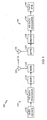
- FIG. 1 is a simplified block diagram of an embodiment of a communications system 100 in which the present invention may be implemented.
- traffic data is sent, typically in frames or packets, from a data source 112 to a transmit (TX) data processor 114 that formats, encodes, and interleaves (i.e., reorders) the data in accordance with a particular processing scheme.
- TX data processor 114 typically further processes signal and control data (e.g:, pilot and power control data).
- a modulator (MOD) 116 then receives, channelizes (i.e., covers), and spreads the processed data to generate symbols that are then converted to analog signals.
- the analog signals are filtered, quadrature modulated, amplified, and upconverted by a transmitter (TMTR) 118 to generate a modulated signal, which is then transmitted via an antenna 120 to one or more receiver units.
- TMTR transmitter
- the transmitted signal is received by an antenna 132 and provided to a receiver (RCVR) 134.
- the received signal is amplified, filtered, downconverted, quadrature demodulated, and digitized to provide data samples: The samples are despread, decovered; and demodulated by a demodulator (DEMOD) 136 to generate demodulated symbols.
- a receive (RX) data processor 138 then reorders and decodes the demodulated symbols to recover the transmitted data.
- the processing performed by demodulator 136 and RX data processor 138 is complementary to the processing performed at transmitter unit 110.
- the recovered data is then provided to a data sink 140.
- the signal processing described above supports transmissions of voice, video, packet data, messaging, and other types of communication in one direction.
- a bi-directional communications system supports two-way data transmission.
- the signal processing for the other direction is not shown in FIG. 1 for simplicity.
- Communications system 100 can be a code division multiple access (CDMA) system, a time division multiple access (TDMA) communications system (e.g., a GSM system), a frequency division multiple access (FDMA) communications system, or other multiple access communications system that supports voice and data communication between users over a terrestrial link.
- CDMA code division multiple access
- TDMA time division multiple access
- FDMA frequency division multiple access
- CDMA systems are typically designed to conform to one or more standards such as the "TIA/EIA/IS-95-A Mobile Station-Base Station Compatibility Standard for Dual-Mode Wideband Spread Spectrum Cellular System” (hereinafter referred to as the IS-95-A standard), the “TIA/EIA/IS-98 Recommended Minimum Standard for Dual-Mode Wideband Spread Spectrum Cellular Mobile Station” (hereinafter referred to as the IS-98 standard), the standard offered by a consortium named "3rd Generation Partnership Project” . (3GPP) and embodied in a set of documents including Document Nos.
- 3GPP 3rd Generation Partnership Project
- 3G TS 25.211, 3G TS 25.212, 3G TS 25.213, and 3G TS 25.214 (hereinafter referred to as the W-CDMA standard), and the "TR-45.5 Physical Layer Standard for cdma2000 Spread Spectrum Systems” (hereinafter referred to as the CDMA-2000 standard).
- W-CDMA standard 3G TS 25.211, 3G TS 25.212, 3G TS 25.213, and 3G TS 25.214
- CDMA-2000 standard 3G TS 25.211, 3G TS 25.212, 3G TS 25.213, and 3G TS 25.214
- CDMA-2000 standard 3G TS 25.211, 3G TS 25.212, 3G TS 25.213, and 3G TS 25.214
- CDMA-2000 standard 3G TS 25.211, 3G TS 25.212, 3G TS 25.213, and 3G TS 25.214
- CDMA-2000 standard 3G TS 25.211, 3
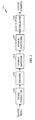
- FIG. 2 is a block diagram of an embodiment of TX data processor 114, which can be designed to implement some embodiments of the present invention.
- Traffic data is received (again, typically in frames or packets) by a frame formatter 212 that formats each received frame in a particular manner.
- frame formatter 212 can perform cycle redundancy check (CRC) coding on each frame of data and append the CRC bits to the frame.
- CRC cycle redundancy check
- Frame formatter 212 typically further adds a number of code-tail bits to the end of each frame.
- the code-tail bits typically have values of zero and are used to set the subsequent encoder to a known state (e.g., all zeros) after the frame has been coded.
- Other frame formatting functions may also be performed by frame formatter 212.
- the formatted frames are then provided to an encoder 214 that codes each frame with a particular coding scheme to generate a corresponding frame of code symbols.
- encoder 214 may perform convolutional or Turbo coding of a data frame.
- the particular coding scheme used is dependent on the particular system or standard being implemented and may be selectable (e.g., different coding schemes may be used for different types of services).
- the coding schemes used for the CDMA-2000 and W-CDMA systems are described in detail in the aforementioned standard documents.
- the coded frames are then provided to a symbol repeater 216.
- a symbol repeater 216 Depending on the number of code symbols generated for a particular frame and the capacity of the frame, zero or more symbols may be repeated.
- M integer number of time
- N ⁇ L the capacity of N symbols
- the number of code symbols after repetition is not equal to the frame size (i.e., the number of code symbols exceeds the capacity of the frame).
- some of the code symbols are deleted (i.e., punctured) so that the resultant number of code symbols matches the capacity of the frame. Symbol repetition and puncturing are described in further detail below.
- the punctured frames are then provided to an interleaver 220.
- the code symbols for each frame are typically written to interleaver 220 in a particular write order (e.g., sequentially) and, after an entire frame has been stored, the code symbols are retrieved in a particular read order that is typically different from the write order to achieve the reordering of the symbols.
- the interleaving scheme is typically defined by the particular system or standard being implemented.
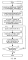
- FIG. 3A is a flow diagram of a conventional symbol puncturing technique, which is described in the CDMA-2000 standard.
- the number of generated code symbols S and the number of required punctures P for a particular frame are determined, at step 312.
- Symbols in the frame are then punctured using the computed distance D .
- symbols in the frame are counted, starting with the first symbol, and the D th symbol is punctured, at step 316.
- the number of required punctures P is decremented, at step 318.
- the conventional symbol puncturing technique described in FIG. 3A can provide varied punctured results, depending on the particular values of S and P .
- the punctured symbols may be evenly distributed throughout the frame for some values of S and P , or may be concentrated in one portion of the frame for some other values of S and P .
- FIG. 3B is a diagram that illustrates a simple example using the conventional symbol puncturing technique described in FIG. 3A .
- the puncture distance D can be computed as 3.
- every 3 rd symbol is punctured, as represented by the boxes with the X.
- the punctured symbols are uniformly distributed across the entire frame.
- FIG. 3C is a diagram that illustrates another simple example using the conventional symbol puncturing technique, but for different values of S and P.
- the puncture distance D can be computed as 2.
- every 2 nd symbol is punctured, as represented by the boxes with the X, until all 11 symbols have been punctured. After the 11 th symbol has been punctured, the remaining symbols are passed unmodified.
- the punctured symbols are concentrated toward the front portion of the frame, while the back portion of the frame is left unchanged.
- the uneven distribution of punctured symbols results from puncturing the symbols with a high puncture rate (i.e., a short puncture distance D).
- FIGS. 3B and 3C illustrate the varied punctured results that can be obtained using the conventional puncturing technique.
- the puncturing pattern changes from a uniform distribution in FIG. 3B to an uneven distribution in FIG. 3C as a result of simply increasing the number of code symbols S by one.
- the conventional puncturing technique thus has "critical" points in which, because of the discrete floor operator ⁇ ⁇ , the puncturing distance D changes by one whole unit when S is increased by one.
- the uneven distribution of the punctured symbols in FIG. 3C can result in performance degradation at the receiver unit. Deletion of symbols is equivalent to reducing the transmit power for those symbols to zero.
- a Viterbi decoder is used at the receiver unit to decode the symbols.
- the Viterbi decoder provides improved performance (i.e., better error correcting capability) if code symbols received in error are more uniformly spread across an entire frame. By puncturing more symbols in one portion of a frame, the Viterbi decoder may not be able to correct symbol errors in that portion of the frame, and an entire frame may be declared erased (i.e., received in error).
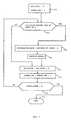
- FIG. 4A is a flow diagram of an embodiment of a symbol puncturing technique of the present invention.
- Symbols in the frame are then punctured using the computed distance D .
- symbols in the frame are counted, initially starting with the first symbol, and the D th symbol is punctured, at step 416.
- step 414 the puncture distance D is recomputed based on the updated values for S and P . Symbols are counted from there onwards and the D th symbol is punctured, at step 416. The process then continues until all P symbols have been punctured.
- the symbol puncturing technique shown in FIG. 4A recomputes the puncture rate (i.e., the puncture distance D) in "real-time” after each puncture.
- the new "puncture distance” i.e., the number of symbols until the next puncture
- the new “puncture distance” is computed based on the number of symbols still remaining and the number of punctures still to be performed. Each computation generates a new puncture distance D that attempts to uniformly distribute the remaining symbol punctures.
- Table 1 lists the parameters S, P, and D for each puncture (i.e., for each pass through the loop shown in FIG. 4A ).
- FIG. 4B is a diagram that shows the results of the puncturing example described in Table 1.
- FIG. 5A is a flow diagram of an embodiment of another symbol puncturing technique of the present invention.
- D1 can be computed with one division operation and D 2 can be computed as D1 + 1.
- D1 can be chosen to equal ⁇ S / P ⁇ and D 2 can be chosen to equal ⁇ S / P ⁇ .
- the number of punctures P1 using puncture distance D1 and the number of punctures P 2 using puncture distance D 2 are then computed, at step 516.
- one of the computed puncture distances is selected, at step 518.
- Various methods can be used to select either D1 or D 2, as described below.
- a symbol in the frame is then punctured using the selected puncture distance.
- symbols in the frame are counted, starting with first symbol in the frame or the last punctured symbol, and the D1 th or D2 th symbol is punctured, at step 520.
- the required number of punctures P1 or P 2 is decremented, depending on which puncture distance has been selected, at step 522. Specifically, P1 is decremented if D1 is selected and P 2 is decremented if D 2 is selected.
- two punctures are performed at the distance of two and nine punctures are performed at the distance of three.
- one of the puncture distances e.g., D1
- one of the puncture distances e.g., D1
- the other puncture distance e.g., D2
- the remaining punctures e.g., P2
- two punctures ( P1 ) can be performed at the distance of two ( D1 ) followed by nine punctures ( P2 ) at the distance of three ( D2 ).
- the puncture distances D1 and D2 are alternately selected and used until all punctures at one of the distances are achieved. The remaining punctures are then performed using the other distance.
- the punctures can be performed using the distances of 2, 3, 2, 3, 3, 3, and so on.
- the P1 punctures at the distance of D1 are approximately distributed among the P2 punctures at the distance of D2 .
- R punctures' are performed using the distance D1 for each puncture using the distance D2 .
- two punctures are performed using the distance of two and nine punctures are performed using the distance of three.
- four or five punctures can be performed using the distance of three for each puncture at the distance of two.
- a weighting algorithm can be used to distribute the P1 punctures at the distance of D1 among the P2 punctures at the distance of D2 .
- intermediate value F P1*N2 - P2 * N1 , wherein N1 and N2 are incremental counters indicating the number of punctures at an iterative round.
- the maximum values for N1 and N2 are chosen so that the puncturing distances P1 and P2 are distributed within the frame.
- the distance D2 is chosen and N2 is incremented by 1 if F ⁇ 0, otherwise the distance D1 is chosen and N1 is incremented by 1.
- the symbol punctures are (approximately) uniformly distributed over the entire frame.
- a "wrap-around" accumulator can be used to store a value that is then used to select the puncture distance for the next puncture.
- the accumulator is designed to store a value ranging from zero to B, where B is typically a power of twos (e.g., 256, 512, 1024, or some other value). B may also be selected to be larger than or equal to the size of the frame (i.e., B ⁇ N). Initially, the smaller value of the punctures P1 and P2 is determined.
- the values in the accumulator can be computed as 227, 454, 681, 908, 111, 338, 565, 792,1019, 222, and 449, before the 1 st , 2 nd , 3 rd , 4 th , 5 th , 6 th , 7 th , 8 th , 9 th , 10 th , and 11 th symbol punctures, respectively.
- the puncture distance D1 is selected for the 5 th and 10 th symbol punctures since the accumulator has wrapped around and has values of 111 and 222, respectively.
- the first puncture at the distance of two can be different. For example, if the accumulator is initialized a the value of 512, then the 3 rd and 7 th punctures are performed at the distance of two and the remaining punctures are performed at the distance of three.
- the computational costs are maintained low. Specifically, only one division operation is performed at step 514 to compute the puncture distances D1 and D2 , which is the same number of division operation as for the conventional puncturing technique shown in FIG. 3A . Thus, the embodiment shown in FIG. 5A provides improved performance at equivalent computation costs.
- FIG. 5B is a diagram that shows the results of the puncturing example described above using the symbol puncturing technique shown in FIG. 5A .
- the 1 st and 6 th punctures are performed using the distance of two and the other punctures are performed using the distance of three.
- the punctures at distances D1 and D2 can also be distributed in various other manners, some of which are described above.
- the symbol puncturing technique of the invention described in FIG. 5A can be generalized to cover N puncture distances.
- the N puncture distances D1 through DN can be computed based on S and P (and possibly other parameters) and used to puncture S code symbols.
- D min ⁇ S P ⁇
- the number of symbol punctures to be performed at each of the puncture distances D1 through DN is then determined.
- P1 through PN symbol punctures are then performed at the distances of D1 through DN, respectively.
- a complementary process is performed at the receiver unit to account for the symbol puncturing performed at the transmitter unit. Specifically, erasures (i.e., "don't knows") are inserted in place of symbols that have been punctured. The erasures are given appropriate weighting during the subsequent decoding process.
- N code symbols are received for a particular frame.
- the number of symbol punctures P that had been performed among S code symbols to generate the N received symbols are then determined.
- a number of puncture distances, D1 through DN is then computed based on S and P.
- P1 through PN symbol punctures that had been performed at the distances of D1 through DN , respectively, are also determined.
- a puncturing pattern used to puncture the S symbols to generate the N received symbols is then derived based on the P1 through PN symbol punctures at the distances of D1 through DN , respectively.
- P erasures are then inserted among the N received symbols based on the derived puncturing pattern to generate S recovered symbols, which are then decoded with a particular decoding scheme. Again, for a more even distribution of the erasures/symbol punctures, each of the distances D1 through DN can be selected to be greater than or equal to a minimum puncture distance Dmin defined above.
- the receiver unit inserts P1 erasures, one after each D1 th received symbols, then inserts P2 erasures, one after each D2 th received symbols.
- the S recovered symbols are then decoded with a particular decoding scheme complementary to the coding scheme used at the transmitter unit.
- FIG. 6 shows plots of the performance achieved with the conventional puncturing technique described in FIG. 3A versus the puncturing technique of the invention.
- the performance results are for the forward link (i.e., from a base station to a user terminal) in the CDMA-2000 system.
- the horizontal axis represents the number of data and CRC bits for each frame.
- the vertical axis represents the average required energy-per-bit-to-total-noise-plus-interference Eb /( No + Ioc ) for a frame error rate (FER) of 1%.
- FER frame error rate
- the simulation results for the conventional puncturing technique are shown by a dashed line 610 in FIG. 6 .
- the results indicate some peaks at approximately periodic intervals. For example, peaks are observed at approximately 300, 600, 1200, and 2400 bits. These peaks result from the uneven symbol puncturing generated by the conventional puncturing technique. The peaks represent the need for a higher average energy per bit Eb to maintain the same FER of 1%.
- the simulation results for the puncturing technique of the invention are shown by a solid line 612 in FIG. 6 .
- the results indicate improvement in performance at some of the peaks. In particular, improvements of approximately 0.5 dB and 1.0 dB are observed at 300 and 600 bits, respectively.
- puncturing may be advantageously performed without using numbers of symbol punctures P1 and P2 or puncture distances D1 and D2 .
- An accumulator is configured to wrap around after it has been incremented to a value that is greater than or equal to S , each increment being of size P , wherein P is a desired number of symbol punctures, S is a total number of received symbols, and N is a frame capacity in symbols (i.e., a number of symbols remaining after puncturing).
- the accumulator is thus a modulo- S accumulator.
- a symbol index is advantageously initialized to one. The symbol index is incremented by one each time the accumulator is incremented by P, until the symbol index reaches the value S. The process is advantageously begun with a puncture.
- a puncture is performed. Nevertheless, one of ordinary skill in the art would readily appreciate that the process need not be initiated with a puncture. Additionally, while the accumulator is advantageously initialized to S, those of skill would understand that the accumulator may be initialized to any value, such as, e.g., zero. Moreover, those of skill would appreciate that the process may instead be run in reverse, so that the symbol index is initially set to the value S, and decremented by one each time the accumulator is incremented by P, until the symbol index reaches one.
- step 700 a field denoted ACC_VALUE is initialized to the value S , and a field denoted SYMBOL_IDX is initialized to one. In other embodiments ACC_VALUE is initialized to values other than S, such as, e.g., zero. Control flow then proceeds to step 702. In step 702 ACC_VALUE is compared with the number S. If ACC_VALUE is greater than or equal to S, control flow proceeds to step 704. If, on the other hand, ACC_VALUE is not greater than or equal to S, control flow proceeds to step 706.
- step 704 ACC_VALUE is decremented by S (i.e., ACC_VALUE is set equal to the difference between ACC_VALUE and S). Control flow then proceeds to step 708. In step 708 a symbol corresponding to the value of SYMBOL_IDX is punctured. Control flow then proceeds to step 706. In step 706 ACC_VALUE is incremented by P (i.e., ACC_VALUE is set equal to the sum of ACC_VALLTE and P). Control flow then proceeds to step 710. In step 710 SYMBOL_IDX is incremented by one (i.e., SYMBOL_IDX is set equal to the sum of SYMBOL_IDX and one). Control flow then proceeds to step 714.
- step 714 SYMBOL_IDX is compared with the value S. If SYMBOL_IDX is greater than S, control flow proceeds to step 712, at which the process stops. If, on the other hand, SYMBOL_IDX is not greater than S, control flow returns to step 702 and the process continues. In other embodiments SYMBOL_IDX is initialized to the value S and the algorithm terminates when SYMBOL_IDX drops below the one.
- the value S / M may be substituted for the value S, and the value P/M may be substituted for the value P in the flowchart of FIG. 7 for ACC_VALUE field (but not in the SYMBOL_IDX field).
- the ACC_VALUE field is initialized to S / M and a modulo- S / M register is used for the accumulator.
- the accumulator is incremented by P/M each increment. Every time the accumulator value exceeds S/M, a modulo- S / M operation is performed and a symbol puncture is done.
- the invention can also be used in other communications systems that employ the same, similar, or different puncturing scheme.
- the invention can be used to perform puncturing in the W-CDMA system and other CDMA systems.
- the symbol puncturing technique of the present invention can also be used on the reverse link (i.e., from the user terminal to the base station).
- the puncturing techniques of the invention can be modified to be more suited for the specific system or standard in which it is used.
- the symbol puncturing techniques of the invention can be implemented in various manners.
- the puncturing techniques can be implemented in hardware within one or more application specific integrated circuits (ASICs), digital signal processors (DSPs), programmable logic device (PLD), controllers, micro-controllers, microprocessors, other electronic units designed to perform the functions described herein, or a combination thereof.
- ASICs application specific integrated circuits
- DSPs digital signal processors
- PLD programmable logic device
- controllers micro-controllers
- microprocessors other electronic units designed to perform the functions described herein, or a combination thereof.
- the puncturing techniques of the invention can be implemented in software or firmware executed on a processor or controller.
- the puncturing techniques of the present invention can also be implemented in a combination of hardware and software.
Applications Claiming Priority (3)
| Application Number | Priority Date | Filing Date | Title |
|---|---|---|---|
| US09/587,168 US6690734B1 (en) | 2000-06-02 | 2000-06-02 | Method and apparatus for puncturing code symbols in a communications system |
| US09/612,158 US6614850B1 (en) | 2000-07-07 | 2000-07-07 | Method and apparatus for puncturing code symbols in a communications system |
| EP01981927.5A EP1301995B1 (de) | 2000-06-02 | 2001-06-04 | Verfahren und vorrichtung zum punktieren von codesymbolen in einem kommunikationssystem |
Related Parent Applications (2)
| Application Number | Title | Priority Date | Filing Date |
|---|---|---|---|
| EP01981927.5A Division EP1301995B1 (de) | 2000-06-02 | 2001-06-04 | Verfahren und vorrichtung zum punktieren von codesymbolen in einem kommunikationssystem |
| EP01981927.5 Division | 2001-06-04 |
Publications (3)
| Publication Number | Publication Date |
|---|---|
| EP2157701A2 true EP2157701A2 (de) | 2010-02-24 |
| EP2157701A3 EP2157701A3 (de) | 2012-12-19 |
| EP2157701B1 EP2157701B1 (de) | 2017-01-11 |
Family
ID=27079928
Family Applications (2)
| Application Number | Title | Priority Date | Filing Date |
|---|---|---|---|
| EP01981927.5A Expired - Lifetime EP1301995B1 (de) | 2000-06-02 | 2001-06-04 | Verfahren und vorrichtung zum punktieren von codesymbolen in einem kommunikationssystem |
| EP09015257.0A Expired - Lifetime EP2157701B1 (de) | 2000-06-02 | 2001-06-04 | Verfahren und Vorrichtung zum Punktieren von Codesymbolen in einem Kommunikationssystem |
Family Applications Before (1)
| Application Number | Title | Priority Date | Filing Date |
|---|---|---|---|
| EP01981927.5A Expired - Lifetime EP1301995B1 (de) | 2000-06-02 | 2001-06-04 | Verfahren und vorrichtung zum punktieren von codesymbolen in einem kommunikationssystem |
Country Status (8)
| Country | Link |
|---|---|
| EP (2) | EP1301995B1 (de) |
| JP (1) | JP4955183B2 (de) |
| KR (2) | KR100782316B1 (de) |
| CN (1) | CN1208905C (de) |
| AU (1) | AU2002211952A1 (de) |
| BR (1) | BR0111281A (de) |
| HK (1) | HK1055020A1 (de) |
| WO (1) | WO2001093431A2 (de) |
Cited By (1)
| Publication number | Priority date | Publication date | Assignee | Title |
|---|---|---|---|---|
| GB2506491A (en) * | 2012-09-14 | 2014-04-02 | Cambridge Silicon Radio Ltd | Using secondary/partial puncture patterns when output data size is not an integer multiple of primary puncture pattern size |
Families Citing this family (5)
| Publication number | Priority date | Publication date | Assignee | Title |
|---|---|---|---|---|
| US6675347B1 (en) | 2000-07-19 | 2004-01-06 | Qualcomm, Incorporated | Method and apparatus for combined puncturing and repeating of code symbols in a communications system |
| KR100845830B1 (ko) * | 2001-12-29 | 2008-07-14 | 엘지전자 주식회사 | 부호 비트 펑처링 방법 |
| EP1416658A1 (de) * | 2002-10-30 | 2004-05-06 | Agilent Technologies Inc. | Leistungseffiziente Symbolverarbeitung |
| US8132072B2 (en) | 2006-01-06 | 2012-03-06 | Qualcomm Incorporated | System and method for providing H-ARQ rate compatible codes for high throughput applications |
| CN101674150B (zh) * | 2008-09-12 | 2013-06-12 | 中兴通讯股份有限公司 | 速率匹配方法和装置 |
Citations (2)
| Publication number | Priority date | Publication date | Assignee | Title |
|---|---|---|---|---|
| US4901307A (en) | 1986-10-17 | 1990-02-13 | Qualcomm, Inc. | Spread spectrum multiple access communication system using satellite or terrestrial repeaters |
| US5103459A (en) | 1990-06-25 | 1992-04-07 | Qualcomm Incorporated | System and method for generating signal waveforms in a cdma cellular telephone system |
Family Cites Families (8)
| Publication number | Priority date | Publication date | Assignee | Title |
|---|---|---|---|---|
| US4908827A (en) * | 1987-07-27 | 1990-03-13 | Tiw Systems, Inc. | Forward error correction system |
| FI104673B (fi) * | 1997-10-24 | 2000-04-14 | Nokia Mobile Phones Ltd | Menetelmä signaalin datanopeuden muuntamiseksi ja lähetin |
| JP2000068862A (ja) * | 1998-08-19 | 2000-03-03 | Fujitsu Ltd | 誤り訂正符号化装置 |
| DE69917307T2 (de) * | 1998-10-07 | 2004-09-30 | Siemens Ag | Vorrichtung und verfahren zur übertragung von punktierten oder wiederholten daten |
| EP1093613A4 (de) * | 1999-04-27 | 2002-02-06 | Hughes Electronics Corp | System und verfahren welches einen geschwindigkeitsanpassungsmechanismus in kommunikationsnetzwerk verwendet |
| WO2001039420A1 (de) * | 1999-11-25 | 2001-05-31 | Siemens Aktiengesellschaft | Verfahren zur anpassung der bitrate in einer kommunikationsvorrichtung und entsprechende kommunikationsvorrichtung |
| EP1240715B1 (de) * | 1999-12-20 | 2008-11-12 | Research In Motion Limited | Hybrid-wiederholungsaufforderungsystem und -verfahren |
| US6690734B1 (en) * | 2000-06-02 | 2004-02-10 | Qualcomm, Incorporated | Method and apparatus for puncturing code symbols in a communications system |
-
2001
- 2001-06-04 AU AU2002211952A patent/AU2002211952A1/en not_active Abandoned
- 2001-06-04 WO PCT/US2001/018252 patent/WO2001093431A2/en active Application Filing
- 2001-06-04 KR KR1020077017645A patent/KR100782316B1/ko not_active IP Right Cessation
- 2001-06-04 KR KR1020027016458A patent/KR100771029B1/ko not_active IP Right Cessation
- 2001-06-04 EP EP01981927.5A patent/EP1301995B1/de not_active Expired - Lifetime
- 2001-06-04 BR BR0111281-3A patent/BR0111281A/pt not_active IP Right Cessation
- 2001-06-04 CN CNB018105882A patent/CN1208905C/zh not_active Expired - Fee Related
- 2001-06-04 JP JP2002500541A patent/JP4955183B2/ja not_active Expired - Fee Related
- 2001-06-04 EP EP09015257.0A patent/EP2157701B1/de not_active Expired - Lifetime
-
2003
- 2003-10-08 HK HK03107215A patent/HK1055020A1/xx not_active IP Right Cessation
Patent Citations (3)
| Publication number | Priority date | Publication date | Assignee | Title |
|---|---|---|---|---|
| US4901307A (en) | 1986-10-17 | 1990-02-13 | Qualcomm, Inc. | Spread spectrum multiple access communication system using satellite or terrestrial repeaters |
| US5103459A (en) | 1990-06-25 | 1992-04-07 | Qualcomm Incorporated | System and method for generating signal waveforms in a cdma cellular telephone system |
| US5103459B1 (en) | 1990-06-25 | 1999-07-06 | Qualcomm Inc | System and method for generating signal waveforms in a cdma cellular telephone system |
Cited By (2)
| Publication number | Priority date | Publication date | Assignee | Title |
|---|---|---|---|---|
| GB2506491A (en) * | 2012-09-14 | 2014-04-02 | Cambridge Silicon Radio Ltd | Using secondary/partial puncture patterns when output data size is not an integer multiple of primary puncture pattern size |
| US8934568B2 (en) | 2012-09-14 | 2015-01-13 | Cambridge Silicon Radio Limited | Data encoding method and apparatus |
Also Published As
| Publication number | Publication date |
|---|---|
| KR20030007846A (ko) | 2003-01-23 |
| AU2002211952A1 (en) | 2001-12-11 |
| JP2003535548A (ja) | 2003-11-25 |
| CN1432214A (zh) | 2003-07-23 |
| KR20070087244A (ko) | 2007-08-27 |
| BR0111281A (pt) | 2003-11-04 |
| JP4955183B2 (ja) | 2012-06-20 |
| WO2001093431A8 (en) | 2002-01-03 |
| EP2157701A3 (de) | 2012-12-19 |
| KR100771029B1 (ko) | 2007-10-29 |
| EP1301995A2 (de) | 2003-04-16 |
| WO2001093431A2 (en) | 2001-12-06 |
| CN1208905C (zh) | 2005-06-29 |
| KR100782316B1 (ko) | 2007-12-06 |
| EP1301995B1 (de) | 2013-04-10 |
| HK1055020A1 (en) | 2003-12-19 |
| EP2157701B1 (de) | 2017-01-11 |
Similar Documents
| Publication | Publication Date | Title |
|---|---|---|
| EP2290825B1 (de) | Punktierung eines Codes mit gleichmässiger Verteilung der Punktierungspositionen | |
| KR100860245B1 (ko) | 코드 분할 다중 접속 시스템에서 역 레이트 매칭을수행하는 방법 및 장치 | |
| AU751048B2 (en) | Method and apparatus for providing error protection for over the air file transfer | |
| EP2134038B1 (de) | Verfahren zur Verbesserung der TFCI-Transportleistung | |
| EP1199834B1 (de) | Verfahren und Anordnung zur Übertragung von Paketdaten in einem Mobilkommunikationssystem | |
| EP1301994B1 (de) | Verfahren und apparat für kombinierte punktierung und wiederhohlung von kodesymbolen in einem kommunikationssystem | |
| EP2157701B1 (de) | Verfahren und Vorrichtung zum Punktieren von Codesymbolen in einem Kommunikationssystem | |
| US6614850B1 (en) | Method and apparatus for puncturing code symbols in a communications system | |
| WO2001093431A1 (en) | Method and apparatus for puncturing code symbols in a communications system | |
| KR20010001083A (ko) | 터보 코드를 위한 레이트 매칭 방법 | |
| KR20010001873A (ko) | 터보 펑쳐링의 성능 개선 방법 |
Legal Events
| Date | Code | Title | Description |
|---|---|---|---|
| PUAI | Public reference made under article 153(3) epc to a published international application that has entered the european phase |
Free format text: ORIGINAL CODE: 0009012 |
|
| 17P | Request for examination filed |
Effective date: 20091209 |
|
| AC | Divisional application: reference to earlier application |
Ref document number: 1301995 Country of ref document: EP Kind code of ref document: P |
|
| AK | Designated contracting states |
Kind code of ref document: A2 Designated state(s): AT BE CH CY DE DK ES FI FR GB GR IE IT LI LU MC NL PT SE TR |
|
| RIN1 | Information on inventor provided before grant (corrected) |
Inventor name: RAZOUMOV, LEONID Inventor name: LING, FUNYUN |
|
| PUAL | Search report despatched |
Free format text: ORIGINAL CODE: 0009013 |
|
| AK | Designated contracting states |
Kind code of ref document: A3 Designated state(s): AT BE CH CY DE DK ES FI FR GB GR IE IT LI LU MC NL PT SE TR |
|
| RIC1 | Information provided on ipc code assigned before grant |
Ipc: H04L 1/00 20060101ALI20121109BHEP Ipc: H03M 13/00 20060101AFI20121109BHEP |
|
| GRAP | Despatch of communication of intention to grant a patent |
Free format text: ORIGINAL CODE: EPIDOSNIGR1 |
|
| INTG | Intention to grant announced |
Effective date: 20160728 |
|
| GRAS | Grant fee paid |
Free format text: ORIGINAL CODE: EPIDOSNIGR3 |
|
| GRAA | (expected) grant |
Free format text: ORIGINAL CODE: 0009210 |
|
| AC | Divisional application: reference to earlier application |
Ref document number: 1301995 Country of ref document: EP Kind code of ref document: P |
|
| AK | Designated contracting states |
Kind code of ref document: B1 Designated state(s): AT BE CH CY DE DK ES FI FR GB GR IE IT LI LU MC NL PT SE TR |
|
| REG | Reference to a national code |
Ref country code: GB Ref legal event code: FG4D |
|
| REG | Reference to a national code |
Ref country code: CH Ref legal event code: EP |
|
| REG | Reference to a national code |
Ref country code: AT Ref legal event code: REF Ref document number: 862118 Country of ref document: AT Kind code of ref document: T Effective date: 20170115 |
|
| REG | Reference to a national code |
Ref country code: IE Ref legal event code: FG4D |
|
| REG | Reference to a national code |
Ref country code: FR Ref legal event code: PLFP Year of fee payment: 17 |
|
| REG | Reference to a national code |
Ref country code: DE Ref legal event code: R096 Ref document number: 60150286 Country of ref document: DE |
|
| PGFP | Annual fee paid to national office [announced via postgrant information from national office to epo] |
Ref country code: FR Payment date: 20170209 Year of fee payment: 17 |
|
| REG | Reference to a national code |
Ref country code: NL Ref legal event code: MP Effective date: 20170111 |
|
| REG | Reference to a national code |
Ref country code: AT Ref legal event code: MK05 Ref document number: 862118 Country of ref document: AT Kind code of ref document: T Effective date: 20170111 |
|
| PG25 | Lapsed in a contracting state [announced via postgrant information from national office to epo] |
Ref country code: NL Free format text: LAPSE BECAUSE OF FAILURE TO SUBMIT A TRANSLATION OF THE DESCRIPTION OR TO PAY THE FEE WITHIN THE PRESCRIBED TIME-LIMIT Effective date: 20170111 |
|
| PG25 | Lapsed in a contracting state [announced via postgrant information from national office to epo] |
Ref country code: GR Free format text: LAPSE BECAUSE OF FAILURE TO SUBMIT A TRANSLATION OF THE DESCRIPTION OR TO PAY THE FEE WITHIN THE PRESCRIBED TIME-LIMIT Effective date: 20170412 Ref country code: FI Free format text: LAPSE BECAUSE OF FAILURE TO SUBMIT A TRANSLATION OF THE DESCRIPTION OR TO PAY THE FEE WITHIN THE PRESCRIBED TIME-LIMIT Effective date: 20170111 |
|
| PG25 | Lapsed in a contracting state [announced via postgrant information from national office to epo] |
Ref country code: AT Free format text: LAPSE BECAUSE OF FAILURE TO SUBMIT A TRANSLATION OF THE DESCRIPTION OR TO PAY THE FEE WITHIN THE PRESCRIBED TIME-LIMIT Effective date: 20170111 Ref country code: PT Free format text: LAPSE BECAUSE OF FAILURE TO SUBMIT A TRANSLATION OF THE DESCRIPTION OR TO PAY THE FEE WITHIN THE PRESCRIBED TIME-LIMIT Effective date: 20170511 Ref country code: ES Free format text: LAPSE BECAUSE OF FAILURE TO SUBMIT A TRANSLATION OF THE DESCRIPTION OR TO PAY THE FEE WITHIN THE PRESCRIBED TIME-LIMIT Effective date: 20170111 Ref country code: SE Free format text: LAPSE BECAUSE OF FAILURE TO SUBMIT A TRANSLATION OF THE DESCRIPTION OR TO PAY THE FEE WITHIN THE PRESCRIBED TIME-LIMIT Effective date: 20170111 |
|
| REG | Reference to a national code |
Ref country code: DE Ref legal event code: R097 Ref document number: 60150286 Country of ref document: DE |
|
| PG25 | Lapsed in a contracting state [announced via postgrant information from national office to epo] |
Ref country code: IT Free format text: LAPSE BECAUSE OF FAILURE TO SUBMIT A TRANSLATION OF THE DESCRIPTION OR TO PAY THE FEE WITHIN THE PRESCRIBED TIME-LIMIT Effective date: 20170111 |
|
| PLBE | No opposition filed within time limit |
Free format text: ORIGINAL CODE: 0009261 |
|
| STAA | Information on the status of an ep patent application or granted ep patent |
Free format text: STATUS: NO OPPOSITION FILED WITHIN TIME LIMIT |
|
| PG25 | Lapsed in a contracting state [announced via postgrant information from national office to epo] |
Ref country code: DK Free format text: LAPSE BECAUSE OF FAILURE TO SUBMIT A TRANSLATION OF THE DESCRIPTION OR TO PAY THE FEE WITHIN THE PRESCRIBED TIME-LIMIT Effective date: 20170111 |
|
| 26N | No opposition filed |
Effective date: 20171012 |
|
| PG25 | Lapsed in a contracting state [announced via postgrant information from national office to epo] |
Ref country code: MC Free format text: LAPSE BECAUSE OF FAILURE TO SUBMIT A TRANSLATION OF THE DESCRIPTION OR TO PAY THE FEE WITHIN THE PRESCRIBED TIME-LIMIT Effective date: 20170111 |
|
| REG | Reference to a national code |
Ref country code: CH Ref legal event code: PL |
|
| REG | Reference to a national code |
Ref country code: IE Ref legal event code: MM4A |
|
| PG25 | Lapsed in a contracting state [announced via postgrant information from national office to epo] |
Ref country code: LI Free format text: LAPSE BECAUSE OF NON-PAYMENT OF DUE FEES Effective date: 20170630 Ref country code: IE Free format text: LAPSE BECAUSE OF NON-PAYMENT OF DUE FEES Effective date: 20170604 Ref country code: CH Free format text: LAPSE BECAUSE OF NON-PAYMENT OF DUE FEES Effective date: 20170630 Ref country code: LU Free format text: LAPSE BECAUSE OF NON-PAYMENT OF DUE FEES Effective date: 20170604 |
|
| REG | Reference to a national code |
Ref country code: BE Ref legal event code: MM Effective date: 20170630 |
|
| PG25 | Lapsed in a contracting state [announced via postgrant information from national office to epo] |
Ref country code: BE Free format text: LAPSE BECAUSE OF NON-PAYMENT OF DUE FEES Effective date: 20170630 |
|
| PGFP | Annual fee paid to national office [announced via postgrant information from national office to epo] |
Ref country code: GB Payment date: 20180403 Year of fee payment: 18 |
|
| REG | Reference to a national code |
Ref country code: DE Ref legal event code: R119 Ref document number: 60150286 Country of ref document: DE |
|
| PG25 | Lapsed in a contracting state [announced via postgrant information from national office to epo] |
Ref country code: DE Free format text: LAPSE BECAUSE OF NON-PAYMENT OF DUE FEES Effective date: 20190101 Ref country code: FR Free format text: LAPSE BECAUSE OF NON-PAYMENT OF DUE FEES Effective date: 20180630 |
|
| PG25 | Lapsed in a contracting state [announced via postgrant information from national office to epo] |
Ref country code: CY Free format text: LAPSE BECAUSE OF NON-PAYMENT OF DUE FEES Effective date: 20170111 |
|
| GBPC | Gb: european patent ceased through non-payment of renewal fee |
Effective date: 20190604 |
|
| PG25 | Lapsed in a contracting state [announced via postgrant information from national office to epo] |
Ref country code: TR Free format text: LAPSE BECAUSE OF FAILURE TO SUBMIT A TRANSLATION OF THE DESCRIPTION OR TO PAY THE FEE WITHIN THE PRESCRIBED TIME-LIMIT Effective date: 20170111 |
|
| PG25 | Lapsed in a contracting state [announced via postgrant information from national office to epo] |
Ref country code: GB Free format text: LAPSE BECAUSE OF NON-PAYMENT OF DUE FEES Effective date: 20190604 |