EP2157594A1 - Vacuum envelope including self-aligning end shield, vacuum interrupter, vacuum circuit interrupter and method including the same - Google Patents
Vacuum envelope including self-aligning end shield, vacuum interrupter, vacuum circuit interrupter and method including the same Download PDFInfo
- Publication number
- EP2157594A1 EP2157594A1 EP09010351A EP09010351A EP2157594A1 EP 2157594 A1 EP2157594 A1 EP 2157594A1 EP 09010351 A EP09010351 A EP 09010351A EP 09010351 A EP09010351 A EP 09010351A EP 2157594 A1 EP2157594 A1 EP 2157594A1
- Authority
- EP
- European Patent Office
- Prior art keywords
- shield
- open end
- ceramic tube
- open
- generally
- Prior art date
- Legal status (The legal status is an assumption and is not a legal conclusion. Google has not performed a legal analysis and makes no representation as to the accuracy of the status listed.)
- Granted
Links
Images



Classifications
-
- H—ELECTRICITY
- H01—ELECTRIC ELEMENTS
- H01H—ELECTRIC SWITCHES; RELAYS; SELECTORS; EMERGENCY PROTECTIVE DEVICES
- H01H33/00—High-tension or heavy-current switches with arc-extinguishing or arc-preventing means
- H01H33/60—Switches wherein the means for extinguishing or preventing the arc do not include separate means for obtaining or increasing flow of arc-extinguishing fluid
- H01H33/66—Vacuum switches
- H01H33/662—Housings or protective screens
- H01H33/66261—Specific screen details, e.g. mounting, materials, multiple screens or specific electrical field considerations
-
- H—ELECTRICITY
- H01—ELECTRIC ELEMENTS
- H01H—ELECTRIC SWITCHES; RELAYS; SELECTORS; EMERGENCY PROTECTIVE DEVICES
- H01H33/00—High-tension or heavy-current switches with arc-extinguishing or arc-preventing means
- H01H33/60—Switches wherein the means for extinguishing or preventing the arc do not include separate means for obtaining or increasing flow of arc-extinguishing fluid
- H01H33/66—Vacuum switches
- H01H33/662—Housings or protective screens
- H01H33/66261—Specific screen details, e.g. mounting, materials, multiple screens or specific electrical field considerations
- H01H2033/66276—Details relating to the mounting of screens in vacuum switches
Definitions
- This invention pertains generally to vacuum interrupters which provide protection in electric power circuits and, more particularly, to vacuum interrupters or vacuum envelopes including end shields that provide a self-alignment function.
- the invention also pertains to a self-alignment method for ends shields of vacuum interrupters.
- the invention further pertains to vacuum circuit interrupters including vacuum interrupters having end shields that provide a self-alignment function.
- Vacuum circuit interrupters provide protection for electrical systems from electrical fault conditions such as current overloads, short circuits, and low level voltage conditions.
- vacuum circuit interrupters include a spring-powered or other suitable operating mechanism, which opens electrical contacts inside a number of vacuum interrupters to interrupt the current flowing through the conductors in an electrical system in response to abnormal conditions.
- Vacuum interrupters include separable main contacts disposed within an insulated and hermetically sealed vacuum chamber.
- the vacuum chamber typically includes a number of sections of ceramics (e.g., a number of tubular ceramic portions) for electrical insulation capped by a number of end members (e.g., metal components, such as metal end plates; end caps; seal cups) to form an envelope in which a vacuum may be drawn.
- the ceramic section is typically cylindrical; however, other suitable cross-sectional shapes may be used. Two end members are typically employed. Where there are multiple ceramic sections, an internal center shield is disposed between the ceramic sections.
- the main contacts are electrically connected to the external circuit to be protected by the vacuum circuit interrupter by electrode stems, typically an elongated member made from high purity copper.
- electrode stems typically an elongated member made from high purity copper.
- a contact and a stem are identified collectively as an electrode.
- one of the contacts is fixed relative to the vacuum chamber as well as to the external circuit.
- the fixed contact is mounted in the vacuum envelope on a first electrode extending through one end member.
- the other contact is movable relative to the vacuum envelope.
- the moveable contact is mounted on a moveable electrode axially slideable through the other end member.
- the movable contact is driven by the operating mechanism and the motion of the operating mechanism is transferred inside the vacuum envelope by a coupling that includes a sealed metallic bellows.
- the fixed and moveable contacts form a pair of separable contacts which are opened and closed by movement of the moveable electrode in response to the operating mechanism located outside of the vacuum envelope.
- the electrodes, end members, bellows, ceramic shell(s), and the internal center shield, if any, are joined together to form a vacuum interrupter capable of maintaining a vacuum at a suitable level for an extended period of time.
- the separable contacts When the separable contacts are opened with current flowing through the vacuum interrupter, a metal-vapor arc is struck between the contact surfaces. This arc continues until the current is interrupted, typically as the alternating current goes through a zero crossing.
- several metal vapor shields are typically provided within the vacuum envelope.
- the metal vapor shields can be between the contacts and the ceramic inside the vacuum envelope, and at one or both ends of the envelope.
- a vacuum envelope including an end shield comprising a first end having an opening therein, a second open end, an intermediate portion disposed between the first end and the second open end, and a flange portion disposed from the second open end.
- the flange portion extends outwardly from the intermediate portion and generally back toward the first end.
- the flange portion includes an edge engaging an inside surface of an end member and is normally offset from an insulative tube of the vacuum envelope.
- a vacuum interrupter comprises: a ceramic tube including a first open end and a second open end; a first end member secured to the first open end of the ceramic tube; a second end member including an inside surface, the second end member secured to the second open end of the ceramic tube, the first and second end members cooperating with the ceramic tube to form a vacuum envelope; an end shield comprising: a first end having an opening therein, a second open end, an intermediate portion disposed between the first end and the second open end of the end shield, and a flange portion disposed from the second open end of the end shield, the flange portion extending outwardly from the intermediate portion and generally back toward the first end, the flange portion including an edge engaging the inside surface of the second end member, the flange portion being normally offset from the ceramic tube; a fixed contact mounted on a fixed electrode extending through the second end member and extending through the opening of the first end of the end shield; and a moveable contact mounted on a moveable electrode extending through
- the intermediate portion and the flange portion of the end shield may form a generally V-shaped structure at the second open end of the end shield;
- the generally V-shaped structure may include a free circular edge forming the edge of the flange portion and an end;
- the inside surface of the second end member may include a cylindrical surface and an end surface normal to the cylindrical surface;
- the free circular edge of the generally V-shaped structure may engage the cylindrical surface;
- the end of the generally V-shaped structure may engage the end surface; and the generally V-shaped structure may be structured to self-align the end shield within the second end member.
- a braze ring may be disposed at the end surface of the second end member and proximate the end of the generally V-shaped structure; and the end of the generally V-shaped structure may be brazed to the end surface of the second end member.
- the end of the generally V-shaped structure may not be secured to the end surface of the second end member; and the end shield may be captured between the end surface of the second end member and the second open end of the ceramic tube.
- the second end member may further include a first end having an opening therein, a second open end, and a cylindrical portion disposed between the first end of the second end member and the second open end of the second end member; the cylindrical portion may form the inside surface; the fixed electrode may extend through the opening of the first end of the second end member; and the second open end of the second end member may be secured to the second open end of the ceramic tube.
- a braze washer may be disposed between the second open end of the second end member and the second open end of the ceramic tube; and the second open end of the second end member may be brazed to the second open end of the ceramic tube.
- Only the intermediate portion of the end shield may engage the ceramic tube.
- the intermediate portion of the end shield may be a generally cylindrical portion including a plurality of dimples which engage the ceramic tube. Only the dimples of the end shield may engage the ceramic tube.
- the second end member may further include a first end, a second open end secured to the second open end of the ceramic tube, and a cylindrical portion disposed between the first end of the second end member and the second open end of the second end member; the cylindrical portion may have a first height; and the flange portion of the end shield may have a second height, which is smaller than the first height, in order that the edge of the flange portion is normally offset from where the second open end of the second end member is secured to the second open end of the ceramic tube.
- a vacuum envelope is for a fixed contact mounted on a fixed electrode and a moveable contact mounted on a moveable electrode.
- the vacuum envelope comprises: an insulative tube including a first open end and a second open end; a first end member secured to the first open end of the insulative tube; a second end member including an inside surface, the second end member secured to the second open end of the insulative tube; and an end shield comprising: a first end having an opening therein, a second open end, an intermediate portion disposed between the first end and the second open end of the end shield, and a flange portion disposed from the second open end of the end shield, the flange portion extending outwardly from the intermediate portion and generally back toward the first end, the flange portion including an edge engaging the inside surface of the second end member, the flange portion being normally offset from the insulative tube.
- a method of self-aligning an end shield of a vacuum interrupter comprises: employing a ceramic tube including a first open end and a second open end; securing a first end member to the first open end of the ceramic tube; securing a second end member to the second open end of the ceramic tube; forming a vacuum envelope with the first and second end members; employing an end shield comprising a first end having an opening therein, a second open end, and an intermediate portion disposed between the first end and the second open end of the end shield; disposing a flange portion including an edge from the second open end of the end shield; extending the flange portion outwardly from the intermediate portion and generally back toward the first end; engaging the edge with the inside surface of the second end member; and offsetting the flange portion from the ceramic tube.
- a vacuum circuit interrupter comprises: a vacuum interrupter comprising: a ceramic tube including a first open end and a second open end, a first end member secured to the first open end of the ceramic tube, a second end member including an inside surface, the second end member secured to the second open end of the ceramic tube, the first and second end members cooperating with the ceramic tube to form a vacuum envelope, an end shield comprising: a first end having an opening therein, a second open end, an intermediate portion disposed between the first end and the second open end of the end shield, and a flange portion disposed from the second open end of the end shield, the flange portion extending outwardly from the intermediate portion and generally back toward the first end, the flange portion including an edge engaging the inside surface of the second end member, the flange portion being normally offset from the ceramic tube, a fixed contact mounted on a fixed electrode extending through the second end member and extending through the opening of the first end of the end shield, and a moveable contact mounted on a
- the intermediate portion of the end shield may be a generally cylindrical portion including a plurality of dimples which engage the ceramic tube; and only the dimples of the end shield may engage the ceramic tube.
- number shall mean one or an integer greater than one (i.e., a plurality).
- the vacuum interrupter 1 includes an insulative tube, such as the example ceramic tube 3, which with end members 5 and 7 forms a vacuum envelope 9.
- a fixed contact 11 is mounted on a fixed electrode 13, which extends through the end member 5.
- a moveable contact 15 is carried by a moveable electrode 17 and extends through the end member 7.
- a bellows 19 forms a seal between the end member 7 and the moveable electrode 17 while allowing axial movement of the moveable electrode 17 to bring the moveable contact 15 into and out of contact with the fixed contact 11.
- the fixed contact 11 and moveable contact 15 form separable contacts 21, which when closed, complete an electrical circuit between the fixed electrode 13 and the moveable electrode 17, and when opened by axial movement of the moveable electrode 17 interrupt current flowing through the vacuum interrupter 1.
- the moveable electrode 17 is moved axially to open and close the separable contacts 21 by an operating mechanism 22 ( Figure 2 ) connected to the moveable electrode 17 outside of the vacuum envelope 9.
- the vapor shield 25 is a floating shield. That is, it is not electrically connected to either electrode 13,17 so that its potential floats. To provide this electrical isolation, the vapor shield 25 is supported by the ceramic tube 3 which, as mentioned, is an electrical insulator.
- the ceramic tube 3 has a groove 29 in the center thereof. A snap ring 31 is popped into that groove 29. The shield 25 is then lowered into the ceramic tube 3 and brazed onto the snap ring 31.
- the invention is applicable to vacuum interrupters including a plurality of ceramic tubes (e.g., without limitation, an upper ceramic and a lower ceramic, with a center shield flange sandwiched therebetween).
- a plurality of ceramic tubes e.g., without limitation, an upper ceramic and a lower ceramic, with a center shield flange sandwiched therebetween.
- the example ceramic tube 3 includes a first open end 33 and a second open end 35.
- the end member 7 is suitably secured (e.g., brazed) to the first open end 33 of the ceramic tube 3.
- the other end member 5 e.g., without limitation, a seal cup
- the end members 5,7 cooperate with the ceramic tube 3 to form the vacuum envelope 9.
- an end shield 39 includes a first end 41 having an opening 43 therein, a second open end 45, an intermediate portion 47 disposed between the first end 41 and the second open end 45, and a flange portion 49 disposed from the second open end 45.
- the flange portion 49 extends outwardly from the intermediate portion 47 and generally back toward the first end 41.
- the flange portion 49 extends outwardly from the intermediate portion 47 at an angle of about 10 degrees, although the flange portion 49 may be generally parallel to the intermediate portion 47 or may be disposed any suitable angle of less than 90 degrees, as long as the edge 51 of the flange portion 49 engages the inside surface 37 of the second end member 5.
- the example flange portion 49 includes the edge 51 engaging the inside surface 37 of the second end member 5.
- the flange portion 49 is normally offset from the ceramic tube 3.
- the fixed contact 11 is mounted on the fixed electrode 13 and extends through the second end member 5 and through the opening 43 of the first end 41 of the end shield 39.
- the moveable contact 15 is mounted on the moveable electrode 17 and extends through the first end member 7 and axially reciprocates into and out of contact with the fixed contact 11.
- the vacuum envelope 9 is for the fixed contact 11 and the moveable contact 15.
- the vacuum envelope 9 includes, for example, the ceramic tube 3, the end members 5,7, and the end shield 39.
- a method of self-aligning the end shield 39 includes employing the ceramic tube 3 including the first open end 33 and the second open end 35; securing the first end member 7 to the first open end 33 of the ceramic tube 3; securing the second end member 5 to the second open end 35 of the ceramic tube 3; forming the vacuum envelope 9 with the first and second end members 5,7; employing the end shield 39 including the first end 41 having the opening 43 therein, the second open end 45, and the intermediate portion 47 disposed between the first end 41 and the second open end 45; disposing the flange portion 49 including the edge 51 from the second open end 45; extending the flange portion 49 outwardly from the intermediate portion 47 and generally back toward the first end 41; engaging the edge 51 with the inside surface 37 of the second end member 5; and offsetting the flange portion 49 from the ceramic tube 3.
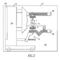
- a vacuum circuit interrupter such as the example vacuum circuit breaker 100, incorporates the vacuum interrupter 1 of Figure 1 .
- the circuit breaker 100 preferably includes a front panel 102, which has controls for manually operating the circuit breaker 100 and changing the state of the separable contacts 21 to either an open or closed condition, and a circuit breaker housing 104.
- the circuit breaker 100 has upper and lower (with respect to Figure 2 ) terminals 106,108, and may have additional terminals not visible in Figure 2 , which can be connected to a line (not shown) and a load (not shown).
- the circuit breaker 100 has a low voltage portion 110 coupled to the front panel 102 and a high voltage portion 112 including the vacuum interrupter 1.
- the vacuum circuit breaker 100 also includes the operating mechanism 22 structured to axially reciprocate the moveable electrode 17 and move the moveable contact 15 ( Figure 1 ) into and out of contact with the fixed contact 11 ( Figure 1 ). Although one pole and one vacuum interrupter 1 are shown, it will be appreciated that the invention is applicable to vacuum circuit interrupters having any number of poles.
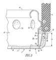
- an end portion of the vacuum interrupter 1 of Figure 1 is shown including the ceramic tube 3, the end shield 39 and the end member 5.
- the intermediate portion 47 of the end shield 39 is a generally cylindrical portion 47 including a plurality of dimples 53 (as best shown in Figures 4 and 5 ) which engage the ceramic tube 3. Only the dimples 53 of the end shield 39 engage the ceramic tube 3.
- the intermediate portion 47 and the flange portion 49 of the end shield 39 form a generally V-shaped structure 55 at the second open end 45 of the end shield 39.
- the generally V-shaped structure 55 includes a free circular edge 57 forming the edge 51 of the flange portion 49 and an end 59, which forms the second open end 45 of the end shield 39.
- the inside surface 37 of the second end member 5 includes a cylindrical surface 61 and an end surface 63 normal to the cylindrical surface 61.
- the free circular edge 57 of the generally V-shaped structure 55 engages the cylindrical surface 61.
- the end 59 of the generally V-shaped structure 55 engages the end surface 63.
- the generally V-shaped structure 55 is structured to self-align the end shield 39 within the second end member 5, while the dimples 53 perform a corresponding self-alignment function of the end shield 39 within the ceramic tube 3.
- a braze ring 65 is disposed at the end surface 63 of the second end member 5 and proximate the end 59 of the generally V-shaped structure 55.
- the end 59 of the generally V-shaped structure 55 is brazed to the end surface 63 of the second end member 5. If the end 59 of the generally V-shaped structure 55 is erroneously not secured to (or if it becomes unsecured from) the end surface 63 of the second end member 5, then the end shield 39 is advantageously captured between the end surface 63 of the second end member 5 and the second open end 35 of the ceramic tube 3.
- a braze washer 67 is disposed between the second open end 69 of the second end member 5 and the second open end 35 of the ceramic tube 3.
- the second open end 69 of the second end member 5 is brazed to the second open end 35 of the ceramic tube 3.
- the intermediate portion 47 of the end shield 39 is a generally cylindrical portion 47 including the dimples 53 which engage the ceramic tube 3.
- the second end member 5 further includes a first end 71, the second open end 69 secured to the second open end 35 of the ceramic tube 3, and a cylindrical portion 73 disposed between the first end 71 and the second open end 69.
- the cylindrical portion 73 has a first height 75.
- the flange portion 49 of the end shield 39 has a second height 77 ( Figure 3 ), which is smaller than the first height 75, in order that the circular edge 51 of the flange portion 49 and the flange portion 49 are normally offset from where the second open end 69 of the second end member 5 is secured to the second open end 35 of the ceramic tube 3.
- the end shield 39 includes a curved flange 78 that engages the inside surface 37 of the end member 5.
- the curved flange 78 provides a self-alignment function, which advantageously acts to align the end shield 39 within the end member 5.
- the end shield 39 also includes the dimples 53, which provide an additional alignment function. The end shield 39 only engages the ceramic tube 3 at the dimples 53.
- a relatively narrow edge 69 of the end member 5 engages the bottom (with respect to Figure 3 ) end 35 of the ceramic tube 3.
- the end member second open end 69 is brazed (e.g., without limitation, using the braze washer 67) to the ceramic tube second open end 35.
- the vacuum interrupter 1 is assembled into the vacuum circuit breaker 100 with the moveable electrode 17 (best shown in Figure 1 ) facing down (with respect to Figure 2 ).
- Figure 3 shows the end member 5 and the end shield 39 for the fixed electrode 13 facing down (with respect to Figure 3 ).
- the end shield 39 does not contact the bottom (with respect to Figure 3 ) end 35 of the ceramic tube 3.
- the end shield 39 on the fixed electrode end was erroneously loose (e.g., caused by a forgotten braze at the braze ring 65), then, in the position shown in Figure 2 , it would "fall".
- the flange portion 49 of the end shield 39 is structured to be slightly lower in height than the corresponding height of the end member 5, in order that it does not interfere with the end member/ceramic tube braze joint.
- the second end member 5 further includes a first end 71 having an opening 79 therein, the second open end 69, and the cylindrical portion 73 ( Figure 6 ) disposed between the first end 71 and the second open end 69.
- the cylindrical portion 73 forms the inside surface 61.
- the fixed electrode 13 extends through the opening 79 of the first end 71 of the second end member 5.
- the second open end 69 of the second end member 5 is secured to the second open end 35 of the ceramic tube 3.
- the advantages of the disclosed vacuum interrupter 1 and end shield 39 include: (1) improved self-alignment as is provided by the flange portion 49 of the end shield 39; (2) a cost savings and an inventory reduction since the self-alignment flange portion 49 centers the end shield 39 within the end member 5, which eliminates an external self-aligning ceramic fixture (not shown), an internal braze ring (not shown) and an internal alignment flange (not shown); (3) elimination of an external self-aligning ceramic fixture and corresponding fixture weight speed up furnace run times and productivity; (4) elimination of an external self-aligning ceramic fixture, which can shield radiant heat from braze joints and result in a relatively poor joint and leaking vacuum interrupters, enable heat to directly penetrate the braze joints, thereby reducing leak-related scrap; (5) error-proofing, since if the end shield-to-end member braze is forgotten, the end shield flange 49 is trapped by the end 35 of the ceramic tube 3, as was discussed above; (6) reduced misalignment through improved self-alignment; and (7) improved productivity
- end shield 39 can be employed with one or both of the end members (e.g., end members 5,7) of a vacuum interrupter.
Landscapes
- High-Tension Arc-Extinguishing Switches Without Spraying Means (AREA)
Abstract
Description
- This invention pertains generally to vacuum interrupters which provide protection in electric power circuits and, more particularly, to vacuum interrupters or vacuum envelopes including end shields that provide a self-alignment function. The invention also pertains to a self-alignment method for ends shields of vacuum interrupters. The invention further pertains to vacuum circuit interrupters including vacuum interrupters having end shields that provide a self-alignment function.
- Vacuum circuit interrupters (e.g., without limitation, vacuum circuit breakers; vacuum switches; load break switches) provide protection for electrical systems from electrical fault conditions such as current overloads, short circuits, and low level voltage conditions. Typically, vacuum circuit interrupters include a spring-powered or other suitable operating mechanism, which opens electrical contacts inside a number of vacuum interrupters to interrupt the current flowing through the conductors in an electrical system in response to abnormal conditions.
- Vacuum interrupters include separable main contacts disposed within an insulated and hermetically sealed vacuum chamber. The vacuum chamber typically includes a number of sections of ceramics (e.g., a number of tubular ceramic portions) for electrical insulation capped by a number of end members (e.g., metal components, such as metal end plates; end caps; seal cups) to form an envelope in which a vacuum may be drawn. The ceramic section is typically cylindrical; however, other suitable cross-sectional shapes may be used. Two end members are typically employed. Where there are multiple ceramic sections, an internal center shield is disposed between the ceramic sections.
- The main contacts are electrically connected to the external circuit to be protected by the vacuum circuit interrupter by electrode stems, typically an elongated member made from high purity copper. A contact and a stem are identified collectively as an electrode. Generally, one of the contacts is fixed relative to the vacuum chamber as well as to the external circuit. The fixed contact is mounted in the vacuum envelope on a first electrode extending through one end member. The other contact is movable relative to the vacuum envelope. The moveable contact is mounted on a moveable electrode axially slideable through the other end member. The movable contact is driven by the operating mechanism and the motion of the operating mechanism is transferred inside the vacuum envelope by a coupling that includes a sealed metallic bellows. The fixed and moveable contacts form a pair of separable contacts which are opened and closed by movement of the moveable electrode in response to the operating mechanism located outside of the vacuum envelope. The electrodes, end members, bellows, ceramic shell(s), and the internal center shield, if any, are joined together to form a vacuum interrupter capable of maintaining a vacuum at a suitable level for an extended period of time.
- When the separable contacts are opened with current flowing through the vacuum interrupter, a metal-vapor arc is struck between the contact surfaces. This arc continues until the current is interrupted, typically as the alternating current goes through a zero crossing. In order to prevent the metal vapor from condensing on the ceramic insulator, several metal vapor shields are typically provided within the vacuum envelope. For example, the metal vapor shields can be between the contacts and the ceramic inside the vacuum envelope, and at one or both ends of the envelope.
- During the manufacturing of sub-assemblies, it is known to use an external alignment flange to align the seal cup and end shield. In addition, during the manufacturing of tube assemblies, external self-aligning ceramic fixtures are used to align the seal cup to the ceramic. These, however, can slow furnace run times, reduce productivity, stick to the sub-assembly and/or shield radiant heat from braze joints causing various components to be decoupled.
- In the event that the end shield is not properly secured in the vacuum interrupter, then electrical shorts can result.
- There is room for improvement in vacuum envelopes and vacuum interrupters employing end shields.
- There is also room for improvement in vacuum circuit interrupters, which employ vacuum interrupters including end shields.
- There is further room for improvements in methods of aligning end shields of vacuum envelopes and vacuum interrupters.
- These needs and others are met by embodiments of the invention, which provide a vacuum envelope including an end shield comprising a first end having an opening therein, a second open end, an intermediate portion disposed between the first end and the second open end, and a flange portion disposed from the second open end. The flange portion extends outwardly from the intermediate portion and generally back toward the first end. The flange portion includes an edge engaging an inside surface of an end member and is normally offset from an insulative tube of the vacuum envelope.
- In accordance with one aspect of the invention, a vacuum interrupter comprises: a ceramic tube including a first open end and a second open end; a first end member secured to the first open end of the ceramic tube; a second end member including an inside surface, the second end member secured to the second open end of the ceramic tube, the first and second end members cooperating with the ceramic tube to form a vacuum envelope; an end shield comprising: a first end having an opening therein, a second open end, an intermediate portion disposed between the first end and the second open end of the end shield, and a flange portion disposed from the second open end of the end shield, the flange portion extending outwardly from the intermediate portion and generally back toward the first end, the flange portion including an edge engaging the inside surface of the second end member, the flange portion being normally offset from the ceramic tube; a fixed contact mounted on a fixed electrode extending through the second end member and extending through the opening of the first end of the end shield; and a moveable contact mounted on a moveable electrode extending through the first end member and axially reciprocating into and out of contact with the fixed contact.
- The intermediate portion and the flange portion of the end shield may form a generally V-shaped structure at the second open end of the end shield; the generally V-shaped structure may include a free circular edge forming the edge of the flange portion and an end; the inside surface of the second end member may include a cylindrical surface and an end surface normal to the cylindrical surface; the free circular edge of the generally V-shaped structure may engage the cylindrical surface; the end of the generally V-shaped structure may engage the end surface; and the generally V-shaped structure may be structured to self-align the end shield within the second end member.
- A braze ring may be disposed at the end surface of the second end member and proximate the end of the generally V-shaped structure; and the end of the generally V-shaped structure may be brazed to the end surface of the second end member.
- The end of the generally V-shaped structure may not be secured to the end surface of the second end member; and the end shield may be captured between the end surface of the second end member and the second open end of the ceramic tube.
- The second end member may further include a first end having an opening therein, a second open end, and a cylindrical portion disposed between the first end of the second end member and the second open end of the second end member; the cylindrical portion may form the inside surface; the fixed electrode may extend through the opening of the first end of the second end member; and the second open end of the second end member may be secured to the second open end of the ceramic tube.
- A braze washer may be disposed between the second open end of the second end member and the second open end of the ceramic tube; and the second open end of the second end member may be brazed to the second open end of the ceramic tube.
- Only the intermediate portion of the end shield may engage the ceramic tube.
- The intermediate portion of the end shield may be a generally cylindrical portion including a plurality of dimples which engage the ceramic tube. Only the dimples of the end shield may engage the ceramic tube.
- The second end member may further include a first end, a second open end secured to the second open end of the ceramic tube, and a cylindrical portion disposed between the first end of the second end member and the second open end of the second end member; the cylindrical portion may have a first height; and the flange portion of the end shield may have a second height, which is smaller than the first height, in order that the edge of the flange portion is normally offset from where the second open end of the second end member is secured to the second open end of the ceramic tube.
- As another aspect of the invention, a vacuum envelope is for a fixed contact mounted on a fixed electrode and a moveable contact mounted on a moveable electrode. The vacuum envelope comprises: an insulative tube including a first open end and a second open end; a first end member secured to the first open end of the insulative tube; a second end member including an inside surface, the second end member secured to the second open end of the insulative tube; and an end shield comprising: a first end having an opening therein, a second open end, an intermediate portion disposed between the first end and the second open end of the end shield, and a flange portion disposed from the second open end of the end shield, the flange portion extending outwardly from the intermediate portion and generally back toward the first end, the flange portion including an edge engaging the inside surface of the second end member, the flange portion being normally offset from the insulative tube.
- As another aspect of the invention, a method of self-aligning an end shield of a vacuum interrupter comprises: employing a ceramic tube including a first open end and a second open end; securing a first end member to the first open end of the ceramic tube; securing a second end member to the second open end of the ceramic tube; forming a vacuum envelope with the first and second end members; employing an end shield comprising a first end having an opening therein, a second open end, and an intermediate portion disposed between the first end and the second open end of the end shield; disposing a flange portion including an edge from the second open end of the end shield; extending the flange portion outwardly from the intermediate portion and generally back toward the first end; engaging the edge with the inside surface of the second end member; and offsetting the flange portion from the ceramic tube.
- As another aspect of the invention, a vacuum circuit interrupter comprises: a vacuum interrupter comprising: a ceramic tube including a first open end and a second open end, a first end member secured to the first open end of the ceramic tube, a second end member including an inside surface, the second end member secured to the second open end of the ceramic tube, the first and second end members cooperating with the ceramic tube to form a vacuum envelope, an end shield comprising: a first end having an opening therein, a second open end, an intermediate portion disposed between the first end and the second open end of the end shield, and a flange portion disposed from the second open end of the end shield, the flange portion extending outwardly from the intermediate portion and generally back toward the first end, the flange portion including an edge engaging the inside surface of the second end member, the flange portion being normally offset from the ceramic tube, a fixed contact mounted on a fixed electrode extending through the second end member and extending through the opening of the first end of the end shield, and a moveable contact mounted on a moveable electrode extending through the first end member and axially reciprocating into and out of contact with the fixed contact; and an operating mechanism structured to axially reciprocate the moveable electrode and move the moveable contact into and out of contact with the fixed contact.
- The intermediate portion of the end shield may be a generally cylindrical portion including a plurality of dimples which engage the ceramic tube; and only the dimples of the end shield may engage the ceramic tube.
- A full understanding of the invention can be gained from the following description of the preferred embodiments when read in conjunction with the accompanying drawings in which:
-
Figure 1 is a longitudinal sectional view through a vacuum interrupter in accordance with embodiments of the invention. -
Figure 2 is a vertical elevation view of a vacuum circuit breaker including the vacuum interrupter ofFigure 1 . -
Figure 3 is a sectional view of a portion of the vacuum interrupter ofFigure 1 showing the ceramic tube, end shield and the end member. -
Figure 4 is an isometric view of the end shield ofFigure 1 . -
Figure 5 is a plan view of the end shield ofFigure 1 . -
Figure 6 is a sectional view of the end member ofFigure 1 . -
Figure 7 is an exploded isometric view of the vacuum interrupter ofFigure 1 . -
Figure 8 is an isometric view of the vacuum interrupter ofFigure 1 . - As employed herein, the term "number" shall mean one or an integer greater than one (i.e., a plurality).
- Referring to
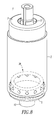
Figures 1 ,7 and8 , avacuum interrupter 1 is shown. Thevacuum interrupter 1 includes an insulative tube, such as the exampleceramic tube 3, which withend members vacuum envelope 9. A fixedcontact 11 is mounted on a fixedelectrode 13, which extends through theend member 5. Amoveable contact 15 is carried by amoveable electrode 17 and extends through theend member 7. A bellows 19 forms a seal between theend member 7 and themoveable electrode 17 while allowing axial movement of themoveable electrode 17 to bring themoveable contact 15 into and out of contact with the fixedcontact 11. The fixedcontact 11 andmoveable contact 15 formseparable contacts 21, which when closed, complete an electrical circuit between the fixedelectrode 13 and themoveable electrode 17, and when opened by axial movement of themoveable electrode 17 interrupt current flowing through thevacuum interrupter 1. Themoveable electrode 17 is moved axially to open and close theseparable contacts 21 by an operating mechanism 22 (Figure 2 ) connected to themoveable electrode 17 outside of thevacuum envelope 9. - When the
separable contacts 21 are opened with current flowing through thevacuum interrupter 1, an arc is struck between the fixedcontact 11 and themoveable contact 15. Thesecontacts vacuum interrupter 1, as is well known. The arc vaporizes metal from thecontacts inner surface 23 of theceramic tube 3 that serves as an electrical insulator, as well as defining thevacuum envelope 9. In order to prevent such deposits, it is well known to provide atubular vapor shield 25 between theseparable contacts 21 and theceramic tube 3. Thistubular vapor shield 25 is generally cylindrical and can be necked down to a degree at each end to extend its protection of theinner surface 23 of theceramic tube 3. It is common to also provide abellows shield 27 mounted on themoveable electrode 17 to protect thebellows 19 from metal-vapor deposits. - The
vapor shield 25 is a floating shield. That is, it is not electrically connected to eitherelectrode vapor shield 25 is supported by theceramic tube 3 which, as mentioned, is an electrical insulator. Theceramic tube 3 has agroove 29 in the center thereof. Asnap ring 31 is popped into thatgroove 29. Theshield 25 is then lowered into theceramic tube 3 and brazed onto thesnap ring 31. - Although a one-piece
ceramic tube 3 is shown, the invention is applicable to vacuum interrupters including a plurality of ceramic tubes (e.g., without limitation, an upper ceramic and a lower ceramic, with a center shield flange sandwiched therebetween). - The example
ceramic tube 3 includes a firstopen end 33 and a secondopen end 35. Theend member 7 is suitably secured (e.g., brazed) to the firstopen end 33 of theceramic tube 3. The other end member 5 (e.g., without limitation, a seal cup) includes aninside surface 37 and is suitably secured (e.g., brazed) to the secondopen end 35 of theceramic tube 3. Theend members ceramic tube 3 to form thevacuum envelope 9. As shown inFigures 1-5 , anend shield 39 includes afirst end 41 having anopening 43 therein, a secondopen end 45, anintermediate portion 47 disposed between thefirst end 41 and the secondopen end 45, and aflange portion 49 disposed from the secondopen end 45. Theflange portion 49 extends outwardly from theintermediate portion 47 and generally back toward thefirst end 41. In the example embodiment, theflange portion 49 extends outwardly from theintermediate portion 47 at an angle of about 10 degrees, although theflange portion 49 may be generally parallel to theintermediate portion 47 or may be disposed any suitable angle of less than 90 degrees, as long as theedge 51 of theflange portion 49 engages theinside surface 37 of thesecond end member 5. - The
example flange portion 49 includes theedge 51 engaging theinside surface 37 of thesecond end member 5. Theflange portion 49 is normally offset from theceramic tube 3. The fixedcontact 11 is mounted on the fixedelectrode 13 and extends through thesecond end member 5 and through theopening 43 of thefirst end 41 of theend shield 39. Themoveable contact 15 is mounted on themoveable electrode 17 and extends through thefirst end member 7 and axially reciprocates into and out of contact with the fixedcontact 11. - The
vacuum envelope 9 is for the fixedcontact 11 and themoveable contact 15. Thevacuum envelope 9 includes, for example, theceramic tube 3, theend members end shield 39. - A method of self-aligning the
end shield 39 includes employing theceramic tube 3 including the firstopen end 33 and the secondopen end 35; securing thefirst end member 7 to the firstopen end 33 of theceramic tube 3; securing thesecond end member 5 to the secondopen end 35 of theceramic tube 3; forming thevacuum envelope 9 with the first andsecond end members end shield 39 including thefirst end 41 having the opening 43 therein, the secondopen end 45, and theintermediate portion 47 disposed between thefirst end 41 and the secondopen end 45; disposing theflange portion 49 including theedge 51 from the secondopen end 45; extending theflange portion 49 outwardly from theintermediate portion 47 and generally back toward thefirst end 41; engaging theedge 51 with theinside surface 37 of thesecond end member 5; and offsetting theflange portion 49 from theceramic tube 3. - As shown in
Figure 2 , a vacuum circuit interrupter, such as the examplevacuum circuit breaker 100, incorporates thevacuum interrupter 1 ofFigure 1 . Thecircuit breaker 100 preferably includes afront panel 102, which has controls for manually operating thecircuit breaker 100 and changing the state of theseparable contacts 21 to either an open or closed condition, and acircuit breaker housing 104. Thecircuit breaker 100 has upper and lower (with respect toFigure 2 ) terminals 106,108, and may have additional terminals not visible inFigure 2 , which can be connected to a line (not shown) and a load (not shown). Thecircuit breaker 100 has alow voltage portion 110 coupled to thefront panel 102 and ahigh voltage portion 112 including thevacuum interrupter 1. Thevacuum circuit breaker 100 also includes theoperating mechanism 22 structured to axially reciprocate themoveable electrode 17 and move the moveable contact 15 (Figure 1 ) into and out of contact with the fixed contact 11 (Figure 1 ). Although one pole and onevacuum interrupter 1 are shown, it will be appreciated that the invention is applicable to vacuum circuit interrupters having any number of poles. - Referring to
Figure 3 , an end portion of thevacuum interrupter 1 ofFigure 1 is shown including theceramic tube 3, theend shield 39 and theend member 5. Theintermediate portion 47 of theend shield 39 is a generallycylindrical portion 47 including a plurality of dimples 53 (as best shown inFigures 4 and 5 ) which engage theceramic tube 3. Only thedimples 53 of theend shield 39 engage theceramic tube 3. - The
intermediate portion 47 and theflange portion 49 of theend shield 39 form a generally V-shapedstructure 55 at the secondopen end 45 of theend shield 39. The generally V-shapedstructure 55 includes a freecircular edge 57 forming theedge 51 of theflange portion 49 and anend 59, which forms the secondopen end 45 of theend shield 39. Theinside surface 37 of thesecond end member 5 includes acylindrical surface 61 and anend surface 63 normal to thecylindrical surface 61. The freecircular edge 57 of the generally V-shapedstructure 55 engages thecylindrical surface 61. Theend 59 of the generally V-shapedstructure 55 engages theend surface 63. The generally V-shapedstructure 55 is structured to self-align theend shield 39 within thesecond end member 5, while thedimples 53 perform a corresponding self-alignment function of theend shield 39 within theceramic tube 3. - A
braze ring 65 is disposed at theend surface 63 of thesecond end member 5 and proximate theend 59 of the generally V-shapedstructure 55. Theend 59 of the generally V-shapedstructure 55 is brazed to theend surface 63 of thesecond end member 5. If theend 59 of the generally V-shapedstructure 55 is erroneously not secured to (or if it becomes unsecured from) theend surface 63 of thesecond end member 5, then theend shield 39 is advantageously captured between theend surface 63 of thesecond end member 5 and the secondopen end 35 of theceramic tube 3. - A
braze washer 67 is disposed between the secondopen end 69 of thesecond end member 5 and the secondopen end 35 of theceramic tube 3. The secondopen end 69 of thesecond end member 5 is brazed to the secondopen end 35 of theceramic tube 3. Only theintermediate portion 47 of theend shield 39 engages theceramic tube 3. In particular, theintermediate portion 47 of theend shield 39 is a generallycylindrical portion 47 including thedimples 53 which engage theceramic tube 3. - Also referring to
Figure 6 , thesecond end member 5 further includes afirst end 71, the secondopen end 69 secured to the secondopen end 35 of theceramic tube 3, and acylindrical portion 73 disposed between thefirst end 71 and the secondopen end 69. Thecylindrical portion 73 has afirst height 75. Theflange portion 49 of theend shield 39 has a second height 77 (Figure 3 ), which is smaller than thefirst height 75, in order that thecircular edge 51 of theflange portion 49 and theflange portion 49 are normally offset from where the secondopen end 69 of thesecond end member 5 is secured to the secondopen end 35 of theceramic tube 3. - The
end shield 39 includes acurved flange 78 that engages theinside surface 37 of theend member 5. Thecurved flange 78 provides a self-alignment function, which advantageously acts to align theend shield 39 within theend member 5. Theend shield 39 also includes thedimples 53, which provide an additional alignment function. Theend shield 39 only engages theceramic tube 3 at thedimples 53. - A relatively
narrow edge 69 of theend member 5 engages the bottom (with respect toFigure 3 ) end 35 of theceramic tube 3. The end member secondopen end 69 is brazed (e.g., without limitation, using the braze washer 67) to the ceramic tube secondopen end 35. - As shown in
Figure 2 , thevacuum interrupter 1 is assembled into thevacuum circuit breaker 100 with the moveable electrode 17 (best shown inFigure 1 ) facing down (with respect toFigure 2 ). In contrast,Figure 3 shows theend member 5 and theend shield 39 for the fixedelectrode 13 facing down (with respect toFigure 3 ). - Continuing to refer to
Figure 3 , normally, theend shield 39 does not contact the bottom (with respect toFigure 3 ) end 35 of theceramic tube 3. Hence; if theend shield 39 on the fixed electrode end was erroneously loose (e.g., caused by a forgotten braze at the braze ring 65), then, in the position shown inFigure 2 , it would "fall". As best shown inFigure 3 , theflange portion 49 of theend shield 39 is structured to be slightly lower in height than the corresponding height of theend member 5, in order that it does not interfere with the end member/ceramic tube braze joint. In the position shown inFigure 2 , if theend shield 39 is erroneously loose, then theend shield 39 is captured against the bottom (with respect toFigure 3 ) end 35 of theceramic tube 3 and will not fall down. Otherwise, without the self-alignment flange 49 of theend shield 39, theend shield 39 could, in theory, touch the shield 25 (Figure 1 ), thereby causing a short. Hence, this provides an error-proofing feature such that if thebraze ring 65 is forgotten, then theend shield 39 will rattle (e.g., between theend member 5 and the ceramic tube 3), but thevacuum interrupter 1 will still function (e.g., interrupt properly) and will not cause a short. - The
second end member 5 further includes afirst end 71 having anopening 79 therein, the secondopen end 69, and the cylindrical portion 73 (Figure 6 ) disposed between thefirst end 71 and the secondopen end 69. Thecylindrical portion 73 forms theinside surface 61. The fixedelectrode 13 extends through theopening 79 of thefirst end 71 of thesecond end member 5. The secondopen end 69 of thesecond end member 5 is secured to the secondopen end 35 of theceramic tube 3. - The advantages of the disclosed
vacuum interrupter 1 and endshield 39 include: (1) improved self-alignment as is provided by theflange portion 49 of theend shield 39; (2) a cost savings and an inventory reduction since the self-alignment flange portion 49 centers theend shield 39 within theend member 5, which eliminates an external self-aligning ceramic fixture (not shown), an internal braze ring (not shown) and an internal alignment flange (not shown); (3) elimination of an external self-aligning ceramic fixture and corresponding fixture weight speed up furnace run times and productivity; (4) elimination of an external self-aligning ceramic fixture, which can shield radiant heat from braze joints and result in a relatively poor joint and leaking vacuum interrupters, enable heat to directly penetrate the braze joints, thereby reducing leak-related scrap; (5) error-proofing, since if the end shield-to-end member braze is forgotten, theend shield flange 49 is trapped by theend 35 of theceramic tube 3, as was discussed above; (6) reduced misalignment through improved self-alignment; and (7) improved productivity through improved self-alignment, since thevacuum interrupter 1 can be built relatively faster. - It will be appreciated that the disclosed
end shield 39 can be employed with one or both of the end members (e.g.,end members 5,7) of a vacuum interrupter. - While specific embodiments of the invention have been described in detail, it will be appreciated by those skilled in the art that various modifications and alternatives to those details could be developed in light of the overall teachings of the disclosure. Accordingly, the particular arrangements disclosed are meant to be illustrative only and not limiting as to the scope of the invention which is to be given the full breadth of the claims appended and any and all equivalents thereof.
-
- 1
- vacuum interrupter
- 3
- ceramic tube
- 5
- end member
- 7
- end member
- 9
- vacuum envelope
- 11
- fixed contact
- 13
- fixed electrode
- 15
- moveable contact
- 17
- moveable electrode
- 19
- bellows
- 21
- separable contacts
- 22
- operating mechanism
- 23
- inner surface
- 25
- tubular vapor shield
- 27
- bellows shield
- 29
- groove
- 31
- snap ring
- 33
- first open end
- 35
- second open end
- 37
- inside surface
- 39
- end shield
- 41
- first end
- 43
- opening
- 45
- second open end
- 47
- intermediate portion
- 49
- flange portion
- 51
- edge
- 53
- dimples
- 55
- V-shaped structure
- 57
- free circular edge
- 59
- end
- 61
- cylindrical surface
- 63
- end surface
- 65
- braze ring
- 67
- braze washer
- 69
- second open end
- 71
- first end
- 73
- cylindrical portion
- 75
- first height
- 77
- second height
- 78
- curved flange
- 79
- opening
- 100
- circuit breaker
- 102
- front panel
- 104
- housing
- 106
- terminal
- 108
- terminal
- 110
- low voltage portion
- 112
- high voltage portion
Claims (15)
- A vacuum interrupter (1) comprising:a ceramic tube (3) including a first open end (33) and a second open end (35);a first end member (7) secured to the first open end of said ceramic tube;a second end member (5) including an inside surface (37), said second end member secured to the second open end of said ceramic tube, said first and second end members cooperating with said ceramic tube to form a vacuum envelope (9);an end shield (39) comprising:a first end (41) having an opening (43) therein,a second open end (45),an intermediate portion (47) disposed between the first end and the second open end of said end shield, anda flange portion (49) disposed from the second open end of said end shield, said flange portion extending outwardly from the intermediate portion and generally back toward the first end, said flange portion including an edge (51) engaging the inside surface of said second end member, said flange portion being normally offset from said ceramic tube;a fixed contact (11) mounted on a fixed electrode (13) extending through said second end member and extending through the opening of the first end of said end shield; anda moveable contact (15) mounted on a moveable electrode (17) extending through said first end member and axially reciprocating into and out of contact with said fixed contact.
- The vacuum interrupter (1) of Claim 1 wherein the intermediate portion and the flange portion of said end shield form a generally V-shaped structure (55) at the second open end of said end shield; wherein said generally V-shaped structure includes a free circular edge (51) forming the edge of said flange portion and an end (59); wherein the inside surface of the second end member includes a cylindrical surface (61) and an end surface (63) normal to said cylindrical surface;
wherein the free circular edge of said generally V-shaped structure engages the cylindrical surface; wherein the end of said generally V-shaped structure engages the end surface; and wherein said generally V-shaped structure is structured to self-align said end shield within said second end member,
wherein preferably a braze ring (65) is disposed at the end surface of said second end member and proximate the end of said generally V-shaped structure; and wherein the end of said generally V-shaped structure is brazed to the end surface of said second end member, and/or
wherein preferably the end of said generally V-shaped structure is not secured to the end surface of said second end member; and wherein said end shield is captured between the end surface of said second end member and the second open end of said ceramic tube. - The vacuum interrupter (1) of Claim 1 wherein said second end member further includes a first end (71) having an opening (79) therein, a second open end (69), and a cylindrical portion (73) disposed between the first end of said second end member and the second open end of said second end member; wherein said cylindrical portion forms the inside surface; wherein the fixed electrode extends through the opening of the first end of said second end member; and wherein the second open end of said second end member is secured to the second open end of said ceramic tube,
wherein preferably a braze washer (67) is disposed between the second open end of said second end member and the second open end of said ceramic tube; and wherein the second open end of said second end member is brazed to the second open end of said ceramic tube. - The vacuum interrupter (1) of Claim 1 wherein only the intermediate portion of said end shield engages said ceramic tube,
wherein preferably the intermediate portion of said end shield is a generally cylindrical portion (47) including a plurality of dimples (53) which engage said ceramic tube,
wherein preferably only the dimples of said end shield engage said ceramic tube. - The vacuum interrupter (1) of Claim 1 wherein said second end member further includes a first end (71), a second open end (69) secured to the second open end of said ceramic tube, and a cylindrical portion (73) disposed between the first end of said second end member and the second open end of said second end member; wherein said cylindrical portion has a first height (75); and wherein the flange portion of said end shield has a second height (77), which is smaller than said first height, in order that the edge of said flange portion is normally offset from where the second open end of said second end member is secured to the second open end of said ceramic tube.
- A vacuum envelope (9) for a fixed contact (11) mounted on a fixed electrode (13) and a moveable contact (15) mounted on a moveable electrode (17), said vacuum envelope comprising:an insulative tube (3) including a first open end (33) and a second open end (35);a first end member (7) secured to the first open end of said insulative tube;a second end member (5) including an inside surface (37), said second end member secured to the second open end of said insulative tube; andan end shield (39) comprising:a first end (41) having an opening (43) therein,a second open end (45),an intermediate portion (47) disposed between the first end and the second open end of said end shield, anda flange portion (49) disposed from the second open end of said end shield, said flange portion extending outwardly from the intermediate portion and generally back toward the first end, said flange portion including an edge (51) engaging the inside surface of the second end member, said flange portion being normally offset from said insulative tube.
- A method of self-aligning an end shield (39) of a vacuum interrupter (1), said method comprising:employing a ceramic tube (3) including a first open end (33) and a second open end (35);securing a first end member (7) to the first open end of said ceramic tube;securing a second end member (5) to the second open end of said ceramic tube;forming a vacuum envelope (9) with said first and second end members;employing an end shield (39) comprising a first end (41) having an opening (43) therein, a second open end (45), and an intermediate portion (47) disposed between the first end and the second open end of said end shield;disposing a flange portion (49) including an edge (51) from the second open end of said end shield;extending said flange portion outwardly from the intermediate portion and generally back toward the first end;engaging said edge with the inside surface of said second end member; andoffsetting said flange portion from said ceramic tube.
- The method of Claim 7 further comprising:forming a generally V-shaped structure (55) at the second open end of said end shield with the intermediate portion and the flange portion of said end shield;including with said generally V-shaped structure a free circular edge (51) forming the edge of said flange portion and an end (59);including with the inside surface of the second end member a cylindrical surface (61) and an end surface (63) normal to said cylindrical surface;engaging the free circular edge of said generally V-shaped structure with the cylindrical surface;engaging the end of said generally V-shaped structure with the end surface; andself-aligning said end shield within said second end member with said generally V-shaped structure.
- The method of Claim 7 further comprising:disposing a braze ring (65) at the end surface of said second end member and proximate the end of said generally V-shaped structure; andbrazing the end of said generally V-shaped structure to the end surface of said second end member.
- The method of Claim 7 further comprising:freeing the end of said generally V-shaped structure from the end surface of said second end member; andcapturing said end shield between the end surface of said second end member and the second open end of said ceramic tube.
- The method of Claim 7 further comprising:including with said second end member a first end (71) having an opening (79) therein, a second open end (69), and a cylindrical portion (73) disposed between the first end of said second end member and the second open end of said second end member;forming the inside surface with said cylindrical portion;extending a fixed electrode (13) through the opening of the first end of said second end member; andsecuring the second open end of said second end member to the second open end of said ceramic tube.
- The method of Claim 7 further comprising:engaging said ceramic tube by said end shield with only the intermediate portion of said end shield.
- The method of Claim 7 further comprising:including with said second end member a first end (75), a second open end (69) secured to the second open end of said ceramic tube, and a cylindrical portion (73) disposed between the first end of said second end member and the second open end of said second end member;employing said cylindrical portion having a first height (79);employing the flange portion of said end shield having a second height (77), which is smaller than said first height; andoffsetting the edge of said flange portion from where the second open end of said second end member is secured to the second open end of said ceramic tube.
- A vacuum circuit interrupter (100) comprising:a vacuum interrupter (1) comprising:a ceramic tube (3) including a first open end (33) and a second open end (35),a first end member (7) secured to the first open end of said ceramic tube,a second end member (5) including an inside surface (37), said second end member secured to the second open end of said ceramic tube, said first and second end members cooperating with said ceramic tube to form a vacuum envelope (9),an end shield (39) comprising:a first end (41) having an opening (43) therein,a second open end (45),an intermediate portion (47) disposed between the first end and the second open end of said end shield, anda flange portion (49) disposed from the second open end of said end shield, said flange portion extending outwardly from the intermediate portion and generally back toward the first end, said flange portion including an edge (51) engaging the inside surface of said second end member, said flange portion being normally offset from said ceramic tube,a fixed contact (11) mounted on a fixed electrode (13) extending through said second end member and extending through the opening of the first end of said end shield, anda moveable contact (15) mounted on a moveable electrode (17) extending through said first end member and axially reciprocating into and out of contact with said fixed contact; andan operating mechanism (22) structured to axially reciprocate the moveable electrode and move said moveable contact into and out of contact with said fixed contact.
- The vacuum circuit interrupter (100) of Claim 14 wherein the intermediate portion and the flange portion of said end shield form a generally V-shaped structure (55) at the second open end of said end shield; wherein said generally V-shaped structure includes a free circular edge (51) forming the edge of said flange portion and an end (59); wherein the inside surface of the second end member includes a cylindrical surface (61) and an end surface (63) normal to said cylindrical surface; wherein the free circular edge of said generally V-shaped structure engages the cylindrical surface; wherein the end of said generally V-shaped structure engages the end surface; and wherein said generally V-shaped structure is structured to self-align said end shield within said second end member,
wherein preferably the end of said generally V-shaped structure is not secured to the end surface of said second end member; and wherein said end shield is captured between the end surface of said second end member and the second open end of said ceramic tube, and/or
wherein preferably the intermediate portion of said end shield is a generally cylindrical portion (47) including a plurality of dimples (53) which engage said ceramic tube; and wherein only the dimples of said end shield engage said ceramic tube.
Applications Claiming Priority (1)
| Application Number | Priority Date | Filing Date | Title |
|---|---|---|---|
| US12/189,320 US8039771B2 (en) | 2008-08-11 | 2008-08-11 | Vacuum envelope including self-aligning end shield, vacuum interrupter, vacuum circuit interrupter and method including the same |
Publications (2)
| Publication Number | Publication Date |
|---|---|
| EP2157594A1 true EP2157594A1 (en) | 2010-02-24 |
| EP2157594B1 EP2157594B1 (en) | 2014-06-04 |
Family
ID=41268164
Family Applications (1)
| Application Number | Title | Priority Date | Filing Date |
|---|---|---|---|
| EP09010351.6A Active EP2157594B1 (en) | 2008-08-11 | 2009-08-11 | Vacuum envelope including self-aligning end shield, vacuum interrupter, vacuum circuit interrupter and method including the same |
Country Status (2)
| Country | Link |
|---|---|
| US (1) | US8039771B2 (en) |
| EP (1) | EP2157594B1 (en) |
Cited By (2)
| Publication number | Priority date | Publication date | Assignee | Title |
|---|---|---|---|---|
| EP2960921A1 (en) * | 2014-06-27 | 2015-12-30 | Schneider Electric Industries SAS | Self-centring assembly for a vacuum tube and vacuum tube |
| CN108352272A (en) * | 2015-11-20 | 2018-07-31 | 伊顿智能动力有限公司 | Maximize the wall thickness of the CU-CR floating center shield assembly by moving the contact gap away from the center flange axial position |
Families Citing this family (19)
| Publication number | Priority date | Publication date | Assignee | Title |
|---|---|---|---|---|
| US8269130B2 (en) * | 2010-02-24 | 2012-09-18 | Eaton Corporation | Retainer, vacuum interrupter, and electrical switching apparatus including the same |
| AU2011276938B2 (en) * | 2010-07-07 | 2015-02-12 | Siemens Ltd. | An electrical isolator |
| DE102011006013B3 (en) | 2011-03-24 | 2012-08-16 | Siemens Aktiengesellschaft | Vacuum interrupter and switch pole |
| KR200464610Y1 (en) * | 2011-09-14 | 2013-01-11 | 엘에스산전 주식회사 | Vacuum interrupter |
| USD703622S1 (en) * | 2012-03-23 | 2014-04-29 | Mitsubishi Electric Corporation | Shield for vacuum circuit breaker |
| RU2532627C2 (en) * | 2012-08-14 | 2014-11-10 | Общество с ограниченной ответственностью "Вакуумные технологии" | Manufacturing method of vacuum arc-extinguishing chambers (vec) |
| US10978256B1 (en) | 2013-03-15 | 2021-04-13 | Innovative Switchgear IP, LLC | Electrical switching device |
| CN104362031B (en) * | 2014-10-31 | 2017-09-29 | 平高集团有限公司 | Tank body and arc-chutes, the high-tension switch gear using the tank body |
| CN104362035B (en) * | 2014-10-31 | 2017-10-10 | 平高集团有限公司 | A kind of high-tension switch gear and its arc-chutes, tank body |
| CN104362535B (en) * | 2014-10-31 | 2017-05-03 | 平高集团有限公司 | Tank, arc extinguish chamber using tank, and sealed switch device |
| US9704658B2 (en) | 2014-11-17 | 2017-07-11 | Eaton Corporation | Vacuum switching apparatus, and contact assembly and method of securing an electrical contact to an electrode therefor |
| KR101697580B1 (en) * | 2015-02-23 | 2017-02-01 | 엘에스산전 주식회사 | Vacuum Interrupter |
| US9842713B2 (en) | 2016-03-30 | 2017-12-12 | Eaton Corporation | Vacuum circuit interrupter |
| WO2017183323A1 (en) | 2016-04-19 | 2017-10-26 | 三菱電機株式会社 | Vacuum valve |
| DE102017222415B4 (en) * | 2017-12-11 | 2021-03-25 | Siemens Aktiengesellschaft | Screen element for a vacuum interrupter |
| USD937331S1 (en) * | 2018-12-19 | 2021-11-30 | Aktiebolaget Skf | Housing for ball bearings |
| CN112164619A (en) * | 2020-11-02 | 2021-01-01 | 陕西宝光真空电器股份有限公司 | Fixing structure of shielding cylinder and ceramic shell and vacuum arc-extinguishing chamber |
| FR3118278A1 (en) * | 2020-12-23 | 2022-06-24 | Schneider Electric Industries Sas | Electrical cut-off contact |
| JP2026511610A (en) * | 2023-03-31 | 2026-04-14 | エス アンド シー エレクトリック カンパニー | Vacuum interrupter with vacuum device shield |
Citations (3)
| Publication number | Priority date | Publication date | Assignee | Title |
|---|---|---|---|---|
| EP0419940A2 (en) * | 1989-09-23 | 1991-04-03 | ABB Calor Emag Schaltanlagen Aktiengesellschaft | Method of manufacture of a housing for a vacuum switch |
| WO2001097242A1 (en) * | 2000-06-16 | 2001-12-20 | Siemens Aktiengesellschaft | Vacuum switch tubes |
| DE10220110A1 (en) * | 2002-05-04 | 2003-11-13 | Abb Patent Gmbh | Vacuum switching chamber for electrical switching systems, has fixed and movable contact parts, and shield attached to holding ring that encloses contact parts in on, isolation and earthing positions |
Family Cites Families (12)
| Publication number | Priority date | Publication date | Assignee | Title |
|---|---|---|---|---|
| JPS58176345U (en) * | 1982-05-20 | 1983-11-25 | 株式会社明電舎 | vacuum interrupter |
| DE3628174A1 (en) | 1986-08-20 | 1988-02-25 | Calor Emag Elektrizitaets Ag | Vacuum switching chamber |
| DE3719256C2 (en) | 1987-06-10 | 1993-11-04 | Calor Emag Elektrizitaets Ag | VACUUM SWITCHING CHAMBER |
| DE3806921A1 (en) * | 1988-03-03 | 1989-09-14 | Calor Emag Elektrizitaets Ag | VACUUM SWITCH CHAMBER |
| GB2308498B (en) | 1995-12-21 | 2000-04-19 | Gec Alsthom Ltd | Electrically conductive shield for a vacuum switching device |
| DE19753031C1 (en) | 1997-11-18 | 1999-04-22 | Siemens Ag | Manufacturing method esp. for vacuum interrupters |
| GB9820717D0 (en) | 1998-09-24 | 1998-11-18 | Alstom Uk Ltd | Improvements relating to vacuum switching devices |
| US6417473B1 (en) * | 2000-07-14 | 2002-07-09 | Eaton Corporation | Method and apparatus for mounting vapor shield in vacuum interrupter and vacuum interrupter incorporating same |
| JP3842735B2 (en) * | 2000-12-13 | 2006-11-08 | シーメンス アクチエンゲゼルシヤフト | Connection between container parts of vacuum circuit breaker and vacuum circuit breaker |
| NL1019651C2 (en) | 2001-12-21 | 2003-06-24 | Holec Holland Nv | Solder ring for manufacturing a vacuum tube, and method for manufacturing such a solder ring and a vacuum tube. |
| US20070007250A1 (en) * | 2005-07-08 | 2007-01-11 | Eaton Corporation | Sealing edge cross-sectional profiles to allow brazing of metal parts directly to a metallized ceramic for vacuum interrupter envelope construction |
| US7781694B2 (en) * | 2007-06-05 | 2010-08-24 | Cooper Technologies Company | Vacuum fault interrupter |
-
2008
- 2008-08-11 US US12/189,320 patent/US8039771B2/en active Active
-
2009
- 2009-08-11 EP EP09010351.6A patent/EP2157594B1/en active Active
Patent Citations (3)
| Publication number | Priority date | Publication date | Assignee | Title |
|---|---|---|---|---|
| EP0419940A2 (en) * | 1989-09-23 | 1991-04-03 | ABB Calor Emag Schaltanlagen Aktiengesellschaft | Method of manufacture of a housing for a vacuum switch |
| WO2001097242A1 (en) * | 2000-06-16 | 2001-12-20 | Siemens Aktiengesellschaft | Vacuum switch tubes |
| DE10220110A1 (en) * | 2002-05-04 | 2003-11-13 | Abb Patent Gmbh | Vacuum switching chamber for electrical switching systems, has fixed and movable contact parts, and shield attached to holding ring that encloses contact parts in on, isolation and earthing positions |
Cited By (4)
| Publication number | Priority date | Publication date | Assignee | Title |
|---|---|---|---|---|
| EP2960921A1 (en) * | 2014-06-27 | 2015-12-30 | Schneider Electric Industries SAS | Self-centring assembly for a vacuum tube and vacuum tube |
| FR3023056A1 (en) * | 2014-06-27 | 2016-01-01 | Schneider Electric Ind Sas | AUTOCENTER ASSEMBLY FOR VACUUM BULB AND VACUUM BULB |
| CN108352272A (en) * | 2015-11-20 | 2018-07-31 | 伊顿智能动力有限公司 | Maximize the wall thickness of the CU-CR floating center shield assembly by moving the contact gap away from the center flange axial position |
| CN108352272B (en) * | 2015-11-20 | 2020-11-24 | 伊顿智能动力有限公司 | Maximize the wall thickness of the CU-CR floating center cowl assembly by moving the contact gap away from the axial position of the center flange |
Also Published As
| Publication number | Publication date |
|---|---|
| EP2157594B1 (en) | 2014-06-04 |
| US8039771B2 (en) | 2011-10-18 |
| US20100032412A1 (en) | 2010-02-11 |
Similar Documents
| Publication | Publication Date | Title |
|---|---|---|
| EP2157594B1 (en) | Vacuum envelope including self-aligning end shield, vacuum interrupter, vacuum circuit interrupter and method including the same | |
| EP2539911B1 (en) | Retainer, vacuum interrupter, and electrical switching apparatus including the same | |
| EP2761639B1 (en) | Vacuum switching apparatus including first and second movable contact assemblies, and vacuum electrical switching apparatus including the same | |
| CN103329234B (en) | Vacuum Interrupter Units for Circuit Breakers | |
| EP3378084B1 (en) | Maximizing wall thickness of a cu-cr floating center shield component by moving contact gap away from center flange axial location | |
| EP1172834B1 (en) | Method and apparatus for mounting vapor shield in vacuum interrupter and vacuum interrupter incorporating same | |
| US4672156A (en) | Vacuum interrupter with bellows shield | |
| EP0241814A2 (en) | Vacuum interrupter | |
| US20120091102A1 (en) | Contact for vacuum interrupter | |
| KR100474173B1 (en) | Insulated Switchgear | |
| KR100972266B1 (en) | Vacuum switch gear | |
| CN111415836A (en) | Vacuum interrupter for vacuum circuit breaker | |
| KR20140101731A (en) | Vacuum switch and electrode assembly therefor | |
| US12308189B2 (en) | Switching device with ceramic/glass eyelets | |
| EP1383148B1 (en) | Vacuum switchgear | |
| KR200401664Y1 (en) | Vacuum Interrupeter Acr Shield Flange | |
| JP2016127744A (en) | Vacuum circuit breaker | |
| US11417479B2 (en) | Arrangement and method for switching high currents in high-, medium- and/or low-voltage engineering | |
| US10541094B1 (en) | Vacuum interrupter with radial bellows | |
| SU662991A1 (en) | High-voltage vacuum switch | |
| JPS63291331A (en) | Patshua type gas circuit breaker |
Legal Events
| Date | Code | Title | Description |
|---|---|---|---|
| PUAI | Public reference made under article 153(3) epc to a published international application that has entered the european phase |
Free format text: ORIGINAL CODE: 0009012 |
|
| AK | Designated contracting states |
Kind code of ref document: A1 Designated state(s): AT BE BG CH CY CZ DE DK EE ES FI FR GB GR HR HU IE IS IT LI LT LU LV MC MK MT NL NO PL PT RO SE SI SK SM TR |
|
| AX | Request for extension of the european patent |
Extension state: AL BA RS |
|
| 17P | Request for examination filed |
Effective date: 20100812 |
|
| GRAP | Despatch of communication of intention to grant a patent |
Free format text: ORIGINAL CODE: EPIDOSNIGR1 |
|
| INTG | Intention to grant announced |
Effective date: 20131118 |
|
| RIN1 | Information on inventor provided before grant (corrected) |
Inventor name: TRONDSEN, WILLIAM J. |
|
| GRAS | Grant fee paid |
Free format text: ORIGINAL CODE: EPIDOSNIGR3 |
|
| GRAA | (expected) grant |
Free format text: ORIGINAL CODE: 0009210 |
|
| AK | Designated contracting states |
Kind code of ref document: B1 Designated state(s): AT BE BG CH CY CZ DE DK EE ES FI FR GB GR HR HU IE IS IT LI LT LU LV MC MK MT NL NO PL PT RO SE SI SK SM TR |
|
| RAP1 | Party data changed (applicant data changed or rights of an application transferred) |
Owner name: EATON CORPORATION |
|
| REG | Reference to a national code |
Ref country code: GB Ref legal event code: FG4D |
|
| REG | Reference to a national code |
Ref country code: CH Ref legal event code: EP |
|
| REG | Reference to a national code |
Ref country code: AT Ref legal event code: REF Ref document number: 671485 Country of ref document: AT Kind code of ref document: T Effective date: 20140615 |
|
| REG | Reference to a national code |
Ref country code: IE Ref legal event code: FG4D |
|
| REG | Reference to a national code |
Ref country code: DE Ref legal event code: R096 Ref document number: 602009024392 Country of ref document: DE Effective date: 20140710 |
|
| REG | Reference to a national code |
Ref country code: AT Ref legal event code: MK05 Ref document number: 671485 Country of ref document: AT Kind code of ref document: T Effective date: 20140604 |
|
| REG | Reference to a national code |
Ref country code: NL Ref legal event code: VDEP Effective date: 20140604 |
|
| PG25 | Lapsed in a contracting state [announced via postgrant information from national office to epo] |
Ref country code: CY Free format text: LAPSE BECAUSE OF FAILURE TO SUBMIT A TRANSLATION OF THE DESCRIPTION OR TO PAY THE FEE WITHIN THE PRESCRIBED TIME-LIMIT Effective date: 20140604 Ref country code: NO Free format text: LAPSE BECAUSE OF FAILURE TO SUBMIT A TRANSLATION OF THE DESCRIPTION OR TO PAY THE FEE WITHIN THE PRESCRIBED TIME-LIMIT Effective date: 20140904 Ref country code: LT Free format text: LAPSE BECAUSE OF FAILURE TO SUBMIT A TRANSLATION OF THE DESCRIPTION OR TO PAY THE FEE WITHIN THE PRESCRIBED TIME-LIMIT Effective date: 20140604 Ref country code: GR Free format text: LAPSE BECAUSE OF FAILURE TO SUBMIT A TRANSLATION OF THE DESCRIPTION OR TO PAY THE FEE WITHIN THE PRESCRIBED TIME-LIMIT Effective date: 20140905 Ref country code: FI Free format text: LAPSE BECAUSE OF FAILURE TO SUBMIT A TRANSLATION OF THE DESCRIPTION OR TO PAY THE FEE WITHIN THE PRESCRIBED TIME-LIMIT Effective date: 20140604 |
|
| REG | Reference to a national code |
Ref country code: LT Ref legal event code: MG4D |
|
| PG25 | Lapsed in a contracting state [announced via postgrant information from national office to epo] |
Ref country code: HR Free format text: LAPSE BECAUSE OF FAILURE TO SUBMIT A TRANSLATION OF THE DESCRIPTION OR TO PAY THE FEE WITHIN THE PRESCRIBED TIME-LIMIT Effective date: 20140604 Ref country code: LV Free format text: LAPSE BECAUSE OF FAILURE TO SUBMIT A TRANSLATION OF THE DESCRIPTION OR TO PAY THE FEE WITHIN THE PRESCRIBED TIME-LIMIT Effective date: 20140604 Ref country code: AT Free format text: LAPSE BECAUSE OF FAILURE TO SUBMIT A TRANSLATION OF THE DESCRIPTION OR TO PAY THE FEE WITHIN THE PRESCRIBED TIME-LIMIT Effective date: 20140604 Ref country code: SE Free format text: LAPSE BECAUSE OF FAILURE TO SUBMIT A TRANSLATION OF THE DESCRIPTION OR TO PAY THE FEE WITHIN THE PRESCRIBED TIME-LIMIT Effective date: 20140604 |
|
| PG25 | Lapsed in a contracting state [announced via postgrant information from national office to epo] |
Ref country code: RO Free format text: LAPSE BECAUSE OF FAILURE TO SUBMIT A TRANSLATION OF THE DESCRIPTION OR TO PAY THE FEE WITHIN THE PRESCRIBED TIME-LIMIT Effective date: 20140604 Ref country code: SK Free format text: LAPSE BECAUSE OF FAILURE TO SUBMIT A TRANSLATION OF THE DESCRIPTION OR TO PAY THE FEE WITHIN THE PRESCRIBED TIME-LIMIT Effective date: 20140604 Ref country code: ES Free format text: LAPSE BECAUSE OF FAILURE TO SUBMIT A TRANSLATION OF THE DESCRIPTION OR TO PAY THE FEE WITHIN THE PRESCRIBED TIME-LIMIT Effective date: 20140604 Ref country code: CZ Free format text: LAPSE BECAUSE OF FAILURE TO SUBMIT A TRANSLATION OF THE DESCRIPTION OR TO PAY THE FEE WITHIN THE PRESCRIBED TIME-LIMIT Effective date: 20140604 Ref country code: EE Free format text: LAPSE BECAUSE OF FAILURE TO SUBMIT A TRANSLATION OF THE DESCRIPTION OR TO PAY THE FEE WITHIN THE PRESCRIBED TIME-LIMIT Effective date: 20140604 Ref country code: PT Free format text: LAPSE BECAUSE OF FAILURE TO SUBMIT A TRANSLATION OF THE DESCRIPTION OR TO PAY THE FEE WITHIN THE PRESCRIBED TIME-LIMIT Effective date: 20141006 |
|
| PG25 | Lapsed in a contracting state [announced via postgrant information from national office to epo] |
Ref country code: PL Free format text: LAPSE BECAUSE OF FAILURE TO SUBMIT A TRANSLATION OF THE DESCRIPTION OR TO PAY THE FEE WITHIN THE PRESCRIBED TIME-LIMIT Effective date: 20140604 Ref country code: IS Free format text: LAPSE BECAUSE OF FAILURE TO SUBMIT A TRANSLATION OF THE DESCRIPTION OR TO PAY THE FEE WITHIN THE PRESCRIBED TIME-LIMIT Effective date: 20141004 Ref country code: NL Free format text: LAPSE BECAUSE OF FAILURE TO SUBMIT A TRANSLATION OF THE DESCRIPTION OR TO PAY THE FEE WITHIN THE PRESCRIBED TIME-LIMIT Effective date: 20140604 |
|
| REG | Reference to a national code |
Ref country code: DE Ref legal event code: R097 Ref document number: 602009024392 Country of ref document: DE |
|
| PG25 | Lapsed in a contracting state [announced via postgrant information from national office to epo] |
Ref country code: MC Free format text: LAPSE BECAUSE OF FAILURE TO SUBMIT A TRANSLATION OF THE DESCRIPTION OR TO PAY THE FEE WITHIN THE PRESCRIBED TIME-LIMIT Effective date: 20140604 Ref country code: LU Free format text: LAPSE BECAUSE OF FAILURE TO SUBMIT A TRANSLATION OF THE DESCRIPTION OR TO PAY THE FEE WITHIN THE PRESCRIBED TIME-LIMIT Effective date: 20140811 |
|
| REG | Reference to a national code |
Ref country code: CH Ref legal event code: PL |
|
| PLBE | No opposition filed within time limit |
Free format text: ORIGINAL CODE: 0009261 |
|
| STAA | Information on the status of an ep patent application or granted ep patent |
Free format text: STATUS: NO OPPOSITION FILED WITHIN TIME LIMIT |
|
| PG25 | Lapsed in a contracting state [announced via postgrant information from national office to epo] |
Ref country code: CH Free format text: LAPSE BECAUSE OF NON-PAYMENT OF DUE FEES Effective date: 20140831 Ref country code: DK Free format text: LAPSE BECAUSE OF FAILURE TO SUBMIT A TRANSLATION OF THE DESCRIPTION OR TO PAY THE FEE WITHIN THE PRESCRIBED TIME-LIMIT Effective date: 20140604 Ref country code: BE Free format text: LAPSE BECAUSE OF NON-PAYMENT OF DUE FEES Effective date: 20140831 Ref country code: IT Free format text: LAPSE BECAUSE OF FAILURE TO SUBMIT A TRANSLATION OF THE DESCRIPTION OR TO PAY THE FEE WITHIN THE PRESCRIBED TIME-LIMIT Effective date: 20140604 Ref country code: LI Free format text: LAPSE BECAUSE OF NON-PAYMENT OF DUE FEES Effective date: 20140831 |
|
| 26N | No opposition filed |
Effective date: 20150305 |
|
| REG | Reference to a national code |
Ref country code: IE Ref legal event code: MM4A |
|
| REG | Reference to a national code |
Ref country code: DE Ref legal event code: R097 Ref document number: 602009024392 Country of ref document: DE Effective date: 20150305 |
|
| PG25 | Lapsed in a contracting state [announced via postgrant information from national office to epo] |
Ref country code: BE Free format text: LAPSE BECAUSE OF FAILURE TO SUBMIT A TRANSLATION OF THE DESCRIPTION OR TO PAY THE FEE WITHIN THE PRESCRIBED TIME-LIMIT Effective date: 20140604 |
|
| PG25 | Lapsed in a contracting state [announced via postgrant information from national office to epo] |
Ref country code: SI Free format text: LAPSE BECAUSE OF FAILURE TO SUBMIT A TRANSLATION OF THE DESCRIPTION OR TO PAY THE FEE WITHIN THE PRESCRIBED TIME-LIMIT Effective date: 20140604 |
|
| PG25 | Lapsed in a contracting state [announced via postgrant information from national office to epo] |
Ref country code: IE Free format text: LAPSE BECAUSE OF NON-PAYMENT OF DUE FEES Effective date: 20140811 |
|
| PG25 | Lapsed in a contracting state [announced via postgrant information from national office to epo] |
Ref country code: SM Free format text: LAPSE BECAUSE OF FAILURE TO SUBMIT A TRANSLATION OF THE DESCRIPTION OR TO PAY THE FEE WITHIN THE PRESCRIBED TIME-LIMIT Effective date: 20140604 |
|
| PG25 | Lapsed in a contracting state [announced via postgrant information from national office to epo] |
Ref country code: BG Free format text: LAPSE BECAUSE OF FAILURE TO SUBMIT A TRANSLATION OF THE DESCRIPTION OR TO PAY THE FEE WITHIN THE PRESCRIBED TIME-LIMIT Effective date: 20140604 Ref country code: MT Free format text: LAPSE BECAUSE OF FAILURE TO SUBMIT A TRANSLATION OF THE DESCRIPTION OR TO PAY THE FEE WITHIN THE PRESCRIBED TIME-LIMIT Effective date: 20140604 |
|
| REG | Reference to a national code |
Ref country code: FR Ref legal event code: PLFP Year of fee payment: 8 |
|
| PG25 | Lapsed in a contracting state [announced via postgrant information from national office to epo] |
Ref country code: TR Free format text: LAPSE BECAUSE OF FAILURE TO SUBMIT A TRANSLATION OF THE DESCRIPTION OR TO PAY THE FEE WITHIN THE PRESCRIBED TIME-LIMIT Effective date: 20140604 Ref country code: HU Free format text: LAPSE BECAUSE OF FAILURE TO SUBMIT A TRANSLATION OF THE DESCRIPTION OR TO PAY THE FEE WITHIN THE PRESCRIBED TIME-LIMIT; INVALID AB INITIO Effective date: 20090811 |
|
| REG | Reference to a national code |
Ref country code: FR Ref legal event code: PLFP Year of fee payment: 9 |
|
| PG25 | Lapsed in a contracting state [announced via postgrant information from national office to epo] |
Ref country code: MK Free format text: LAPSE BECAUSE OF FAILURE TO SUBMIT A TRANSLATION OF THE DESCRIPTION OR TO PAY THE FEE WITHIN THE PRESCRIBED TIME-LIMIT Effective date: 20140604 |
|
| REG | Reference to a national code |
Ref country code: FR Ref legal event code: PLFP Year of fee payment: 10 |
|
| REG | Reference to a national code |
Ref country code: GB Ref legal event code: 732E Free format text: REGISTERED BETWEEN 20181115 AND 20181130 |
|
| REG | Reference to a national code |
Ref country code: DE Ref legal event code: R082 Ref document number: 602009024392 Country of ref document: DE Ref country code: DE Ref legal event code: R081 Ref document number: 602009024392 Country of ref document: DE Owner name: EATON INTELLIGENT POWER LIMITED, IE Free format text: FORMER OWNER: EATON CORP., CLEVELAND, OHIO, US |
|
| P01 | Opt-out of the competence of the unified patent court (upc) registered |
Effective date: 20230521 |
|
| PGFP | Annual fee paid to national office [announced via postgrant information from national office to epo] |
Ref country code: DE Payment date: 20250724 Year of fee payment: 17 |
|
| PGFP | Annual fee paid to national office [announced via postgrant information from national office to epo] |
Ref country code: GB Payment date: 20250724 Year of fee payment: 17 |
|
| PGFP | Annual fee paid to national office [announced via postgrant information from national office to epo] |
Ref country code: FR Payment date: 20250725 Year of fee payment: 17 |