EP2157378A2 - Indoor embedded type heat source machine - Google Patents
Indoor embedded type heat source machine Download PDFInfo
- Publication number
- EP2157378A2 EP2157378A2 EP09167299A EP09167299A EP2157378A2 EP 2157378 A2 EP2157378 A2 EP 2157378A2 EP 09167299 A EP09167299 A EP 09167299A EP 09167299 A EP09167299 A EP 09167299A EP 2157378 A2 EP2157378 A2 EP 2157378A2
- Authority
- EP
- European Patent Office
- Prior art keywords
- air
- drain pan
- drain
- air inlet
- source machine
- Prior art date
- Legal status (The legal status is an assumption and is not a legal conclusion. Google has not performed a legal analysis and makes no representation as to the accuracy of the status listed.)
- Granted
Links
Images



Classifications
-
- F—MECHANICAL ENGINEERING; LIGHTING; HEATING; WEAPONS; BLASTING
- F24—HEATING; RANGES; VENTILATING
- F24F—AIR-CONDITIONING; AIR-HUMIDIFICATION; VENTILATION; USE OF AIR CURRENTS FOR SCREENING
- F24F1/00—Room units for air-conditioning, e.g. separate or self-contained units or units receiving primary air from a central station
- F24F1/06—Separate outdoor units, e.g. outdoor unit to be linked to a separate room comprising a compressor and a heat exchanger
- F24F1/36—Drip trays for outdoor units
-
- F—MECHANICAL ENGINEERING; LIGHTING; HEATING; WEAPONS; BLASTING
- F24—HEATING; RANGES; VENTILATING
- F24F—AIR-CONDITIONING; AIR-HUMIDIFICATION; VENTILATION; USE OF AIR CURRENTS FOR SCREENING
- F24F1/00—Room units for air-conditioning, e.g. separate or self-contained units or units receiving primary air from a central station
- F24F1/06—Separate outdoor units, e.g. outdoor unit to be linked to a separate room comprising a compressor and a heat exchanger
-
- F—MECHANICAL ENGINEERING; LIGHTING; HEATING; WEAPONS; BLASTING
- F24—HEATING; RANGES; VENTILATING
- F24F—AIR-CONDITIONING; AIR-HUMIDIFICATION; VENTILATION; USE OF AIR CURRENTS FOR SCREENING
- F24F1/00—Room units for air-conditioning, e.g. separate or self-contained units or units receiving primary air from a central station
- F24F1/06—Separate outdoor units, e.g. outdoor unit to be linked to a separate room comprising a compressor and a heat exchanger
- F24F1/60—Arrangement or mounting of the outdoor unit
-
- F—MECHANICAL ENGINEERING; LIGHTING; HEATING; WEAPONS; BLASTING
- F24—HEATING; RANGES; VENTILATING
- F24F—AIR-CONDITIONING; AIR-HUMIDIFICATION; VENTILATION; USE OF AIR CURRENTS FOR SCREENING
- F24F1/00—Room units for air-conditioning, e.g. separate or self-contained units or units receiving primary air from a central station
- F24F1/06—Separate outdoor units, e.g. outdoor unit to be linked to a separate room comprising a compressor and a heat exchanger
- F24F1/60—Arrangement or mounting of the outdoor unit
- F24F1/64—Ceiling-mounted, e.g. below a balcony
-
- F—MECHANICAL ENGINEERING; LIGHTING; HEATING; WEAPONS; BLASTING
- F24—HEATING; RANGES; VENTILATING
- F24F—AIR-CONDITIONING; AIR-HUMIDIFICATION; VENTILATION; USE OF AIR CURRENTS FOR SCREENING
- F24F13/00—Details common to, or for air-conditioning, air-humidification, ventilation or use of air currents for screening
- F24F13/22—Means for preventing condensation or evacuating condensate
- F24F13/222—Means for preventing condensation or evacuating condensate for evacuating condensate
-
- F—MECHANICAL ENGINEERING; LIGHTING; HEATING; WEAPONS; BLASTING
- F24—HEATING; RANGES; VENTILATING
- F24F—AIR-CONDITIONING; AIR-HUMIDIFICATION; VENTILATION; USE OF AIR CURRENTS FOR SCREENING
- F24F2221/00—Details or features not otherwise provided for
- F24F2221/14—Details or features not otherwise provided for mounted on the ceiling
Definitions
- the present invention relates to an indoor embedded type heat source machine embedded in a ceiling of a building or the like, and more particular, to an indoor embedded type heat source machine having a drain pan.
- a heat source machine performs a defrosting operation for removal of frost and ice, which adhere to a heat exchanger. Therefore, a drain water is generated in the defrosting operation. Since a heat source machine is normally mounted outdoors, a drain water is not subjected to special treatment but is drained outdoors by gravity. Since an indoor embedded type heat source machine is mounted in a ceiling of a building or the like, however, it is necessary to retain a drain water in a drain pan to drain the same outside. At this time, it is an important problem to prevent a water from leaking into a room and to prevent a dew condensation water from falling.
- JP-A-62-186142 describes a conventional technology.
- a ceiling embedded type heat source machine shown in the document is provided in a ceiling space together with an indoor unit and an outdoor unit.
- a drain water generated by a heat-source side heat exchanger is conducted to a utilization side heat exchanger through a drain pipe to be evaporated to humidify an interior of a room and a drain water being not evaporated is discharged outside the room by a drain pump.
- a drain water generated by the utilization side heat exchanger is characteristically discharged outside the room by the drain pump.
- the invention has a feature in an indoor embedded type heat source machine comprising a cabinet mounted in an interior of a building and embedded in a ceiling, a floor, or a wall, which surrounds an air-conditioning object environment, a separating plate that partitions the cabinet into an air inlet space and an air outlet space, an air inlet, through which an air is drawn into the air inlet space, an air outlet, through which an air is blown off from the air outlet space, a fan provided on a side of the air inlet space toward the separating plate to blow off an air into the air outlet space from the air inlet space, a compressor provided in the air inlet space and arranged to make a length direction thereof in parallel to a surface of the ceiling, the floor, or the wall, in which it is embedded, a heat exchanger provided between the fan and the compressor, a drain pan provided below the compressor to have drainage means, and/or a heat-exchanger separating plate that partitions the drain pan into a side, on which an air flows into the
- the invention has a further feature in an indoor embedded type heat source machine comprising a cabinet mounted in an interior of a building and embedded in a ceiling, a floor, or a wall, which surrounds an air-conditioning object environment, a separating plate that partitions the cabinet into an air inlet space and an air outlet space, an air inlet, through which an air is drawn into the air inlet space, an air outlet, through which an air is blown off from the air outlet space, a fan provided in the air inlet space, a fan motor that drives the fan, a compressor provided in the air inlet space and arranged to make a length direction thereof in parallel to a surface of the ceiling, the floor, or the wall, in which it is embedded, a heat exchanger provided between the fan and the compressor, a drain pan provided below the compressor, a heat-exchanger separating plate that partitions the drain pan into a side, on which an air flows into the heat exchanger, and a side, on which an air flows out from the heat exchanger, and/or drainage means provided on
- the drain pan in the indoor embedded type heat source machine preferably comprises means for detection of a drain water retained therein.
- the drain pan in the indoor embedded type heat source machine preferably comprises a drain pump that receives an electric signal from the detection means to start or stop an operation, in which a drain water is drawn up.
- the drain pan in the indoor embedded type heat source machine preferably comprises a heater.
- an antibacterial treatment is preferably applied to the drain pan in the indoor embedded type heat source machine.
- the drain pan in the indoor embedded type heat source machine is preferably arranged on a reinforcement member provided in a lower portion of the cabinet.
- a cabinet mounted in an interior of a building is partitioned into an air inlet space and an air outlet space by a separating plate, a fan is provided on a side of the air inlet space toward the separating plate, a compressor is provided in the air inlet space in a manner to make a length direction thereof substantially in parallel to the ceiling or the like, in which it is embedded, and which comprises a heat exchanger between the fan and the compressor, a drain pan provided below the compressor to have drainage means, and a heat-exchanger separating plate that partitions the drain pan into a side, on which an air flows into the heat exchanger, and a side, on which an air flows out from the heat exchanger, it is possible to obtain an indoor embedded type heat source machine constructed to have a thin, compact cabinet.
- the drain pan partitioned into a side, on which an air flows into the heat exchanger, and a side, on which an air flows out, by the heat-exchanger separating plate produces an effect of enabling efficiently draining a drain water from drainage means since the side, on which an air flows out, becomes negative in pressure to collect a drain water.
- An indoor embedded type heat source machine is constructed such that a separating plate 17 compartments an air inlet space provided with an air inlet 10 and an air outlet space provided with an air outlet 11 as shown in Fig. 1 .
- a compressor 1 a receiver 6, a heat exchanger 2, a fan motor 3, and a fan 4.
- an electrical box 5 is arranged in the air outlet space.
- Fig. 1 shows the case where the machine is suspended in, for example, the ceiling.
- Fig. 2 is a view illustrating the configuration of a refrigerating cycle in the embodiment.
- a refrigerating cycle is constituted by successively connecting the compressor 1, the reversing valve 7, the heat exchanger 2, and the receiver 6 in tube-in-tube and circulating a refrigerant.
- Fig. 3 shows the drain pan 9 of the indoor embedded type heat source machine according to the embodiment.
- an air conditioner performs a heating operation
- a dew condensation water adheres to the heat exchanger 2.
- a defrosting operation is carried out periodically to perform thawing and defrosting. Therefore, a large quantity of drain water is generated.
- an outdoor equipment of a general air conditioner is mounted outdoors, a drain water is drained by gravity but an indoor embedded type heat source machine is mounted indoors, so that it is essential to retain a drain water in the drain pan 9 and to discharge the drain water by means of a drain hose, or the like.
- the drain pan 9 is also made L-shaped. Also, a drain boss (drain discharge port) 9a for discharge of a drain water is provided on a side or a bottom surface of the drain pan 9.
- the drain boss 9a may be provided in a single location or several locations. In the case where the drain bosses 9a are provided in several locations, a water is hard to leak even if the drain boss in a location is plugged with foreign matters, and a direction, in which a drain water is discharged, can be optionally changed according to a location, in which a cabinet 18 is mounted.
- a drain water is stored in the drain pan 9, it is preferable to apply a rustproof treatment, coating treatment, or the like in the case where a drain pan is made of sheet metal. Also, in the case where a long period of time elapses as a drain water is left in the drain pan 9, mold and bacteria propagate in the drain water to lead to the generation of foreign matters on slime and odor in some cases.
- an antibacterial treatment may be applied on surfaces of the drain pan 9.
- FIG. 3 indicate flow of an air flowing from the air inlet, a side, on which an air flows into the heat exchanger 2, being referred to as a heat-exchanger primary side, and a side, on which an air flows out from the heat exchanger 2, being referred to as a heat-exchanger secondary side.
- the heat-exchanger primary side and the heat-exchanger secondary side are partitioned by heat-exchanger separating plates 2a, 2b.
- the drain boss 9a for discharge of a drain water, provided on the drain pan 9 is arranged on the heat-exchanger secondary side.
- the fan motor 3 and the fan 4 are arranged on the heat-exchanger secondary side of the drain pan 9 partitioned by the heat-exchanger separating plates 2a, 2b, so that the heat-exchanger secondary side is made negative in pressure upon the operation of the fan. Therefore, a drain water stored in the drain pan 9 is caused by the negative pressure to rise in water level on the heat-exchanger secondary side. Accordingly, when the drain boss 9a is provided on the heat-exchanger secondary side, a drain water is well drained.
- drain bosses 9a are preferably provided on an opposite side of the cabinet 18 to the air inlet 10 for reasons of installation of a distributing water pipe (not shown) and maintenance.
- the indoor embedded type heat source machine is installed so that the compressor 1 is laid down on the ceiling but the indoor embedded type heat source machine may be embedded in, for example, a floor or a wall. In case of being provided on a wall, the indoor embedded type heat source machine is installed so that the compressor 1 is made substantially in parallel to the wall.
- the heat exchanger 2 In the case where a heating operation is to be performed when an outside air is low in temperature, the heat exchanger 2 is lowered to or below 0 °C in temperature and a drain water temporarily stored in the drain pan 9 freezes in some cases. Ordinarily, a defrosting operation is performed to raise the heat exchanger 2 in temperature to melt ice in the heat exchanger 2 and the drain pan 9 but ice cannot be completely melted but remains in some cases in the case where an outside air is low in temperature. When ice remains, ice accumulates with the lapse of time and the whole drain pan 9 freezes to finally lead to leakage of water from the drain pan 9.
- crankcase heater 14 By providing a crankcase heater 14 on a bottom surface (an opposite side to a surface, on which a drain water is collected) of the drain pan 9 as shown in Fig. 4 , it is possible to prevent the drain pan 9 from freezing.
- an electric current may be carried to the crankcase heater 14 by a signal from a temperature sensor mounted to the heat exchanger 2.
- Fig. 5 shows a drain pan according to Embodiment 2 of the invention and corresponds to a view as viewed in a direction of an arrow A-A in Fig. 3 .
- the drain pan 9 in Embodiment 1 permits drainage by gravity from the drain bosses 9a. Therefore, in the case where dust accumulates on the drain pan 9 and mold generates on the drain pan 9 to leave slime-like foreign matters, the drain bosses 9a are plugged to lead to a decrease in performance of drainage.
- a float switch 12 is mounted in the embodiment to issue an alarm in the case where the drain pan 9 becomes abnormal in water level as shown in Fig. 5 or the operation of an outdoor equipment is stopped. At this time, an indoor equipment is also stopped in operation or an air blasting operation is performed.
- the float switch 12 be fixed by means of a fixing plate 13. It is required that a level, at which the float switch 12 is mounted, with reference to a lower surface of the drain pan 9 be made one, at which an alarm is issued in case of abnormal water level, and one, at which the float switch 12 is not actuated in normal operation. Also, it is simply required that the float switch 12 be mounted on the secondary side of the heat exchanger 2.
- Fig. 6 shows an example, in which a drain pump 15 is provided on a drain pan 9 to draw up a drain water stored in the drain pan 9.
- the drain pump 15 is fixed by means of a fixing plate 16.
- a drain water drawn up by the drain pump 15 is drained through a drain hose 19. It suffices that the drain pump 15 be operated receiving a signal when the float switch 12 operates. Also, it suffices that an operation of the drain pump 15 be stopped receiving a signal when the operation of the float switch 12 (see Fig. 5 ) is released. Since the drain pump 15 is mounted to enable lifting a drain water by a pump head of 700 mm at maximum, there is an advantage that execution of drain piping is improved in flexibility, or the like.
- drain pan 9 since a drain water from the heat exchanger 2 is stored in the drain pan 9, a load is placed on the drain pan 9.
- the drain pan 9 in order to prevent the drain pan 9 from bending, it is preferred that the drain pan 9 be arranged on a transverse reinforcement member 8a and a longitudinal reinforcement member 8b, which are provided on a bottom plate 8. Drain-pan fixing stays 9b are mounted to the drain pan 9, and the bottom plate 8 and the drain pan 9 are clamped together by means of screws or the like.
- a drain water In the case where a drain water is very large in quantity, the drain water overflows from the drain pan 9 to lead to leakage of water from an outdoor equipment.
- a drain water can be retained by bending four end surfaces of the bottom plate 8 disposed on a lowermost surface of the cabinet 18 to form a box from the same.
- the bottom plate 8 can retain a water to prevent leakage of water from the indoor embedded type heat source machine even if a water leaks from and a dew condensation water drops from the drain pan 9.
Landscapes
- Engineering & Computer Science (AREA)
- Chemical & Material Sciences (AREA)
- Combustion & Propulsion (AREA)
- Mechanical Engineering (AREA)
- General Engineering & Computer Science (AREA)
- Devices For Blowing Cold Air, Devices For Blowing Warm Air, And Means For Preventing Water Condensation In Air Conditioning Units (AREA)
- Other Air-Conditioning Systems (AREA)
Abstract
Description
- The present invention relates to an indoor embedded type heat source machine embedded in a ceiling of a building or the like, and more particular, to an indoor embedded type heat source machine having a drain pan.
- Generally, while an outdoor equipment (heat source machine) of an air conditioner is mounted outdoors, an air conditioner of a type, of which a heat source machine is mounted in the interior of a building, is desired by scene control regulations or the like in recent years. Accordingly, it is required that a heat source machine be thin and lightweight to enable mounting in a ceiling, a clearance of which is narrow.
- Also, in a heating operation, a heat source machine performs a defrosting operation for removal of frost and ice, which adhere to a heat exchanger. Therefore, a drain water is generated in the defrosting operation. Since a heat source machine is normally mounted outdoors, a drain water is not subjected to special treatment but is drained outdoors by gravity. Since an indoor embedded type heat source machine is mounted in a ceiling of a building or the like, however, it is necessary to retain a drain water in a drain pan to drain the same outside. At this time, it is an important problem to prevent a water from leaking into a room and to prevent a dew condensation water from falling.
-
JP-A-62-186142 - However, it is not adequately taken into consideration to thin the construction described in
JP-A-62-186142 - It is an object of the invention to provide an indoor embedded type heat source machine capable of efficiently draining a drain water collected in a drain pan provided on a thin, compact cabinet.
- In order to attain the object, the invention has a feature in an indoor embedded type heat source machine comprising a cabinet mounted in an interior of a building and embedded in a ceiling, a floor, or a wall, which surrounds an air-conditioning object environment, a separating plate that partitions the cabinet into an air inlet space and an air outlet space, an air inlet, through which an air is drawn into the air inlet space, an air outlet, through which an air is blown off from the air outlet space, a fan provided on a side of the air inlet space toward the separating plate to blow off an air into the air outlet space from the air inlet space, a compressor provided in the air inlet space and arranged to make a length direction thereof in parallel to a surface of the ceiling, the floor, or the wall, in which it is embedded, a heat exchanger provided between the fan and the compressor, a drain pan provided below the compressor to have drainage means, and/or a heat-exchanger separating plate that partitions the drain pan into a side, on which an air flows into the heat exchanger, and a side, on which an air flows out from the heat exchanger.
- The invention has a further feature in an indoor embedded type heat source machine comprising a cabinet mounted in an interior of a building and embedded in a ceiling, a floor, or a wall, which surrounds an air-conditioning object environment, a separating plate that partitions the cabinet into an air inlet space and an air outlet space, an air inlet, through which an air is drawn into the air inlet space, an air outlet, through which an air is blown off from the air outlet space, a fan provided in the air inlet space, a fan motor that drives the fan, a compressor provided in the air inlet space and arranged to make a length direction thereof in parallel to a surface of the ceiling, the floor, or the wall, in which it is embedded, a heat exchanger provided between the fan and the compressor, a drain pan provided below the compressor, a heat-exchanger separating plate that partitions the drain pan into a side, on which an air flows into the heat exchanger, and a side, on which an air flows out from the heat exchanger, and/or drainage means provided on the drain pan on a side, on which an air from the heat exchanger flows out.
- Also, the drain pan in the indoor embedded type heat source machine preferably comprises means for detection of a drain water retained therein.
- Also, the drain pan in the indoor embedded type heat source machine preferably comprises a drain pump that receives an electric signal from the detection means to start or stop an operation, in which a drain water is drawn up.
- Also, the drain pan in the indoor embedded type heat source machine preferably comprises a heater.
- Also, an antibacterial treatment is preferably applied to the drain pan in the indoor embedded type heat source machine.
- Also, the drain pan in the indoor embedded type heat source machine is preferably arranged on a reinforcement member provided in a lower portion of the cabinet.
- According to the invention, owing to a construction, in which a cabinet mounted in an interior of a building is partitioned into an air inlet space and an air outlet space by a separating plate, a fan is provided on a side of the air inlet space toward the separating plate, a compressor is provided in the air inlet space in a manner to make a length direction thereof substantially in parallel to the ceiling or the like, in which it is embedded, and which comprises a heat exchanger between the fan and the compressor, a drain pan provided below the compressor to have drainage means, and a heat-exchanger separating plate that partitions the drain pan into a side, on which an air flows into the heat exchanger, and a side, on which an air flows out from the heat exchanger, it is possible to obtain an indoor embedded type heat source machine constructed to have a thin, compact cabinet. Further, the drain pan partitioned into a side, on which an air flows into the heat exchanger, and a side, on which an air flows out, by the heat-exchanger separating plate produces an effect of enabling efficiently draining a drain water from drainage means since the side, on which an air flows out, becomes negative in pressure to collect a drain water.
-
-
Fig. 1 is a view showing the construction of configuration of Embodiment 1 of an indoor embedded type heat source machine according to the invention; -
Fig. 2 is a view illustrating the configuration of a refrigerating cycle in Embodiment 1; -
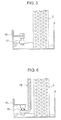
Fig. 3 is a view showing the construction of configuration of the neighborhood of a drain pan shown inFig. 1 ; -
Fig. 4 is a view showing how a crankcase heater on a back surface of the drain pan shown inFig. 3 is mounted; -
Fig. 5 is a view as viewed in a direction of an arrow A-A inFig. 3 in the case where a float switch is mounted; -
Fig. 6 is a view as viewed in the direction of the arrow A-A inFig. 3 in the case where a drain pump is mounted; and -
Fig. 7 is a view showing the construction of a bottom plate of a cabinet shown inFig. 1 . - Embodiments according to the invention will be described below with reference to the drawings.
- An indoor embedded type heat source machine according to an embodiment is constructed such that a separating
plate 17 compartments an air inlet space provided with an air inlet 10 and an air outlet space provided with an air outlet 11 as shown inFig. 1 . Arranged in the air inlet space are a compressor 1, a receiver 6, a heat exchanger 2, afan motor 3, and a fan 4. Also, a reversing valve, an outdoor expansion valve, cycle piping, etc., which constitute a refrigerating cycle, are provided in the air inlet space and a drain pan 9 is arranged below the heat exchanger 2. On the other hand, an electrical box 5 is arranged in the air outlet space.Fig. 1 shows the case where the machine is suspended in, for example, the ceiling. -
Fig. 2 is a view illustrating the configuration of a refrigerating cycle in the embodiment. A refrigerating cycle is constituted by successively connecting the compressor 1, the reversing valve 7, the heat exchanger 2, and the receiver 6 in tube-in-tube and circulating a refrigerant. -
Fig. 3 shows the drain pan 9 of the indoor embedded type heat source machine according to the embodiment. When an air conditioner performs a heating operation, a dew condensation water adheres to the heat exchanger 2. Also, since a water content and a dew condensation water adhering to the heat exchanger freeze when an outside air is low in temperature, a defrosting operation is carried out periodically to perform thawing and defrosting. Therefore, a large quantity of drain water is generated. Since an outdoor equipment of a general air conditioner is mounted outdoors, a drain water is drained by gravity but an indoor embedded type heat source machine is mounted indoors, so that it is essential to retain a drain water in the drain pan 9 and to discharge the drain water by means of a drain hose, or the like. - Since the heat exchanger 2 is L-shaped, the drain pan 9 is also made L-shaped. Also, a drain boss (drain discharge port) 9a for discharge of a drain water is provided on a side or a bottom surface of the drain pan 9. The
drain boss 9a may be provided in a single location or several locations. In the case where thedrain bosses 9a are provided in several locations, a water is hard to leak even if the drain boss in a location is plugged with foreign matters, and a direction, in which a drain water is discharged, can be optionally changed according to a location, in which acabinet 18 is mounted. - Since a drain water is stored in the drain pan 9, it is preferable to apply a rustproof treatment, coating treatment, or the like in the case where a drain pan is made of sheet metal. Also, in the case where a long period of time elapses as a drain water is left in the drain pan 9, mold and bacteria propagate in the drain water to lead to the generation of foreign matters on slime and odor in some cases. Hereupon, in order to suppress the generation of bacteria or the like, an antibacterial treatment may be applied on surfaces of the drain pan 9.
- Arrows in
Fig. 3 indicate flow of an air flowing from the air inlet, a side, on which an air flows into the heat exchanger 2, being referred to as a heat-exchanger primary side, and a side, on which an air flows out from the heat exchanger 2, being referred to as a heat-exchanger secondary side. The heat-exchanger primary side and the heat-exchanger secondary side are partitioned by heat-exchanger separating plates 2a, 2b. - The
drain boss 9a, for discharge of a drain water, provided on the drain pan 9 is arranged on the heat-exchanger secondary side. According to the embodiment, thefan motor 3 and the fan 4 are arranged on the heat-exchanger secondary side of the drain pan 9 partitioned by the heat-exchanger separatingplates 2a, 2b, so that the heat-exchanger secondary side is made negative in pressure upon the operation of the fan. Therefore, a drain water stored in the drain pan 9 is caused by the negative pressure to rise in water level on the heat-exchanger secondary side. Accordingly, when thedrain boss 9a is provided on the heat-exchanger secondary side, a drain water is well drained. While the provision of a plurality ofdrain bosses 9a as in the embodiment achieves an improvement in quality of drainage, thedrain bosses 9a are preferably provided on an opposite side of thecabinet 18 to the air inlet 10 for reasons of installation of a distributing water pipe (not shown) and maintenance. - In addition, according to the embodiment, the indoor embedded type heat source machine is installed so that the compressor 1 is laid down on the ceiling but the indoor embedded type heat source machine may be embedded in, for example, a floor or a wall. In case of being provided on a wall, the indoor embedded type heat source machine is installed so that the compressor 1 is made substantially in parallel to the wall.
- In the case where a heating operation is to be performed when an outside air is low in temperature, the heat exchanger 2 is lowered to or below 0 °C in temperature and a drain water temporarily stored in the drain pan 9 freezes in some cases. Ordinarily, a defrosting operation is performed to raise the heat exchanger 2 in temperature to melt ice in the heat exchanger 2 and the drain pan 9 but ice cannot be completely melted but remains in some cases in the case where an outside air is low in temperature. When ice remains, ice accumulates with the lapse of time and the whole drain pan 9 freezes to finally lead to leakage of water from the drain pan 9.
- By providing a
crankcase heater 14 on a bottom surface (an opposite side to a surface, on which a drain water is collected) of the drain pan 9 as shown inFig. 4 , it is possible to prevent the drain pan 9 from freezing. When thecrankcase heater 14 is lowered to or below a predetermined temperature, an electric current may be carried to thecrankcase heater 14 by a signal from a temperature sensor mounted to the heat exchanger 2. -
Fig. 5 shows a drain pan according to Embodiment 2 of the invention and corresponds to a view as viewed in a direction of an arrow A-A inFig. 3 . The drain pan 9 in Embodiment 1 permits drainage by gravity from thedrain bosses 9a. Therefore, in the case where dust accumulates on the drain pan 9 and mold generates on the drain pan 9 to leave slime-like foreign matters, thedrain bosses 9a are plugged to lead to a decrease in performance of drainage. In order to prevent leakage of water from the drain pan 9 in this case, afloat switch 12 is mounted in the embodiment to issue an alarm in the case where the drain pan 9 becomes abnormal in water level as shown inFig. 5 or the operation of an outdoor equipment is stopped. At this time, an indoor equipment is also stopped in operation or an air blasting operation is performed. - It is simply required that the
float switch 12 be fixed by means of a fixingplate 13. It is required that a level, at which thefloat switch 12 is mounted, with reference to a lower surface of the drain pan 9 be made one, at which an alarm is issued in case of abnormal water level, and one, at which thefloat switch 12 is not actuated in normal operation. Also, it is simply required that thefloat switch 12 be mounted on the secondary side of the heat exchanger 2. -
Fig. 6 shows an example, in which adrain pump 15 is provided on a drain pan 9 to draw up a drain water stored in the drain pan 9. Thedrain pump 15 is fixed by means of a fixingplate 16. A drain water drawn up by thedrain pump 15 is drained through adrain hose 19. It suffices that thedrain pump 15 be operated receiving a signal when thefloat switch 12 operates. Also, it suffices that an operation of thedrain pump 15 be stopped receiving a signal when the operation of the float switch 12 (seeFig. 5 ) is released. Since thedrain pump 15 is mounted to enable lifting a drain water by a pump head of 700 mm at maximum, there is an advantage that execution of drain piping is improved in flexibility, or the like. - Also, since a drain water from the heat exchanger 2 is stored in the drain pan 9, a load is placed on the drain pan 9. Hereupon, as shown in
Fig. 7 , in order to prevent the drain pan 9 from bending, it is preferred that the drain pan 9 be arranged on atransverse reinforcement member 8a and alongitudinal reinforcement member 8b, which are provided on a bottom plate 8. Drain-pan fixing stays 9b are mounted to the drain pan 9, and the bottom plate 8 and the drain pan 9 are clamped together by means of screws or the like. - In the case where a drain water is very large in quantity, the drain water overflows from the drain pan 9 to lead to leakage of water from an outdoor equipment. Hereupon, a drain water can be retained by bending four end surfaces of the bottom plate 8 disposed on a lowermost surface of the
cabinet 18 to form a box from the same. When the bottom plate 8 thus formed is used, the bottom plate 8 can retain a water to prevent leakage of water from the indoor embedded type heat source machine even if a water leaks from and a dew condensation water drops from the drain pan 9. - Features, components and specific details of the structures of the above-described embodiments may be exchanged or combined to form further embodiments optimized for the respective application. As far as those modifications are apparent for an expert skilled in the art they shall be disclosed implicitly by the above description without specifying explicitly every possible combination.
Claims (7)
- An indoor embedded type heat source machine comprising
a cabinet (18) mounted in an interior of a building and embedded in a ceiling, a floor, or a wall, which surrounds an air-conditioning object environment,
a separating plate (17) that partitions the cabinet (18) into an air inlet space and an air outlet space,
an air inlet (10), through which an air is drawn into the air inlet space,
an air outlet (11), through which an air is blown off from the air outlet space,
a fan (4) provided on a side of the air inlet space toward the separating plate (17) to blow off an air into the air outlet space from the air inlet space,
a compressor (1) provided in the air inlet space and arranged to make a length direction thereof in parallel to a surface of the ceiling, the floor, or the wall, in which it is embedded,
a heat exchanger (2) provided between the fan (4) and the compressor (1),
a drain pan (9) provided below the compressor (1) to have drainage means, and
a heat-exchanger separating plate (2a, 2b) that partitions the drain pan (9) into a side, on which an air flows into the heat exchanger (2), and a side, on which an air flows out from the heat exchanger (2). - An indoor embedded type heat source machine comprising
a cabinet (18) mounted in an interior of a building and embedded in a ceiling, a floor, or a wall, which surrounds an air-conditioning object environment,
a separating plate (17) that partitions the cabinet (18) into an air inlet space and an air outlet space,
an air inlet (10), through which an air is drawn into the air inlet space,
an air outlet (11), through which an air is blown off from the air outlet space,
a fan (4) provided in the air inlet space,
a fan motor (3) that drives the fan (4),
a compressor (1) provided in the air inlet space and arranged to make a length direction thereof in parallel to a surface of the ceiling, the floor, or the wall, in which it is embedded,
a heat exchanger (12) provided between the fan (4) and the compressor (1),
a drain pan (9) provided below the compressor (1),
a heat-exchanger separating plate (2a, 2b) that partitions the drain pan into a side, on which an air flows into the heat exchanger (2), and a side, on which an air flows out from the heat exchanger (2), and
drainage means provided on the drain pan (9) on a side, on which an air from the heat exchanger (2) flows out. - The indoor embedded type heat source machine according to claim 1 or 2, wherein the drain pan (9) comprises means for detection of a drain water retained therein.
- The indoor embedded type heat source machine according to claim 3, wherein the drain pan (9) comprises a drain pump (15) that receives an electric signal from the detection means to start or stop an operation, in which a drain water is drawn up.
- The indoor embedded type heat source machine according to claim 1 or 2, wherein the drain pan (9) comprises a heater (14).
- The indoor embedded type heat source machine according to claim 1 or 2, wherein an antibacterial treatment is applied to the drain pan (9).
- The indoor embedded type heat source machine according to claim 1 or 2, wherein the drain pan (9) is arranged on a reinforcement member provided in a lower portion of the cabinet (18).
Applications Claiming Priority (1)
| Application Number | Priority Date | Filing Date | Title |
|---|---|---|---|
| JP2008213447A JP4734386B2 (en) | 2008-08-22 | 2008-08-22 | Indoor embedded heat source machine |
Publications (3)
| Publication Number | Publication Date |
|---|---|
| EP2157378A2 true EP2157378A2 (en) | 2010-02-24 |
| EP2157378A3 EP2157378A3 (en) | 2014-09-03 |
| EP2157378B1 EP2157378B1 (en) | 2018-02-28 |
Family
ID=41402363
Family Applications (1)
| Application Number | Title | Priority Date | Filing Date |
|---|---|---|---|
| EP09167299.8A Active EP2157378B1 (en) | 2008-08-22 | 2009-08-05 | Indoor embedded type heat source machine |
Country Status (4)
| Country | Link |
|---|---|
| EP (1) | EP2157378B1 (en) |
| JP (1) | JP4734386B2 (en) |
| CN (1) | CN101655263B (en) |
| ES (1) | ES2668847T3 (en) |
Cited By (2)
| Publication number | Priority date | Publication date | Assignee | Title |
|---|---|---|---|---|
| CN102022783A (en) * | 2010-12-31 | 2011-04-20 | 广东欧科空调制冷有限公司 | A floor trough fan coil unit |
| CN119309254A (en) * | 2024-11-26 | 2025-01-14 | 珠海格力电器股份有限公司 | Heat exchanger, air conditioner and air conditioner control method |
Families Citing this family (2)
| Publication number | Priority date | Publication date | Assignee | Title |
|---|---|---|---|---|
| CN105650846A (en) * | 2014-11-28 | 2016-06-08 | 青岛海高设计制造有限公司 | Air conditioner |
| CN111336671A (en) * | 2018-12-19 | 2020-06-26 | 彭志军 | Air conditioner part device with ultrasonic cleaning function |
Citations (1)
| Publication number | Priority date | Publication date | Assignee | Title |
|---|---|---|---|---|
| JPS62186142A (en) | 1986-02-07 | 1987-08-14 | Sanyo Electric Co Ltd | Air conditioner buried in ceiling |
Family Cites Families (12)
| Publication number | Priority date | Publication date | Assignee | Title |
|---|---|---|---|---|
| JPS5876064U (en) * | 1981-11-19 | 1983-05-23 | 三洋電機株式会社 | Air conditioner outdoor unit |
| JPS5876064A (en) * | 1982-10-01 | 1983-05-09 | Fuji Oil Co Ltd | Production of soybean fermented food |
| FR2601001B1 (en) * | 1986-07-02 | 1988-11-10 | Rhone Poulenc Chim Base | PROCESS FOR THE CHLORINATION OF PHENOLIC COMPOUNDS |
| JPH0332902Y2 (en) * | 1986-07-29 | 1991-07-12 | ||
| FR2603997B1 (en) * | 1986-09-15 | 1988-12-16 | Essilor Int | EYEGLASS FRAME |
| JPH0410497Y2 (en) * | 1986-11-05 | 1992-03-16 | ||
| JPH08271024A (en) * | 1995-03-31 | 1996-10-18 | Toshiba Ave Corp | Air conditioner |
| AU757671B2 (en) * | 1998-11-27 | 2003-02-27 | Mitsubishi Denki Kabushiki Kaisha | Indoor unit for an air conditioner |
| TW457358B (en) * | 1999-09-09 | 2001-10-01 | Tadahiro Omi | Apparatus and method for highly efficiently controlling temperature and humidity of gas |
| JP4280114B2 (en) * | 2003-06-09 | 2009-06-17 | 東芝キヤリア株式会社 | Air conditioner |
| JP2005172260A (en) * | 2003-12-08 | 2005-06-30 | Matsushita Electric Ind Co Ltd | Air conditioner |
| KR100575304B1 (en) * | 2003-12-19 | 2006-05-02 | 엘지전자 주식회사 | Indoor unit of air conditioner |
-
2008
- 2008-08-22 JP JP2008213447A patent/JP4734386B2/en active Active
-
2009
- 2009-08-05 ES ES09167299.8T patent/ES2668847T3/en active Active
- 2009-08-05 EP EP09167299.8A patent/EP2157378B1/en active Active
- 2009-08-12 CN CN2009101658807A patent/CN101655263B/en active Active
Patent Citations (1)
| Publication number | Priority date | Publication date | Assignee | Title |
|---|---|---|---|---|
| JPS62186142A (en) | 1986-02-07 | 1987-08-14 | Sanyo Electric Co Ltd | Air conditioner buried in ceiling |
Cited By (2)
| Publication number | Priority date | Publication date | Assignee | Title |
|---|---|---|---|---|
| CN102022783A (en) * | 2010-12-31 | 2011-04-20 | 广东欧科空调制冷有限公司 | A floor trough fan coil unit |
| CN119309254A (en) * | 2024-11-26 | 2025-01-14 | 珠海格力电器股份有限公司 | Heat exchanger, air conditioner and air conditioner control method |
Also Published As
| Publication number | Publication date |
|---|---|
| JP2010048471A (en) | 2010-03-04 |
| EP2157378B1 (en) | 2018-02-28 |
| ES2668847T3 (en) | 2018-05-22 |
| JP4734386B2 (en) | 2011-07-27 |
| CN101655263A (en) | 2010-02-24 |
| CN101655263B (en) | 2012-08-22 |
| EP2157378A3 (en) | 2014-09-03 |
Similar Documents
| Publication | Publication Date | Title |
|---|---|---|
| US11441813B2 (en) | Indoor unit of refrigeration apparatus | |
| KR101340725B1 (en) | Water cooling type air conditioner | |
| KR102436213B1 (en) | HVAC management system, HVAC management method, and program | |
| EP3150928B1 (en) | Indoor unit of air conditioner | |
| KR20120116973A (en) | Chilling unit | |
| JPWO2020059006A1 (en) | Refrigeration cycle equipment | |
| US20230114621A1 (en) | Air conditioner | |
| EP2157378B1 (en) | Indoor embedded type heat source machine | |
| EP2436993B1 (en) | Air conditioning device specialized for heating | |
| WO2018142583A1 (en) | Refrigeration system | |
| CN111051782B (en) | Outdoor unit of air conditioner | |
| JP7014982B2 (en) | Image processing equipment, air processing system, image processing program, and image processing method | |
| JP6595139B1 (en) | Air conditioning management system, air conditioning management method, and program | |
| KR100606733B1 (en) | Indoor unit of multi air conditioner | |
| JP4308090B2 (en) | Air conditioner | |
| JP3817240B2 (en) | Engine heat pump | |
| JP3757225B2 (en) | Engine heat pump | |
| JP2025112559A (en) | air conditioning equipment | |
| JP4251775B2 (en) | Air conditioning system | |
| JP2006184003A (en) | Air conditioner | |
| CN1570492A (en) | Household central air-conditioner |
Legal Events
| Date | Code | Title | Description |
|---|---|---|---|
| PUAI | Public reference made under article 153(3) epc to a published international application that has entered the european phase |
Free format text: ORIGINAL CODE: 0009012 |
|
| AK | Designated contracting states |
Kind code of ref document: A2 Designated state(s): AT BE BG CH CY CZ DE DK EE ES FI FR GB GR HR HU IE IS IT LI LT LU LV MC MK MT NL NO PL PT RO SE SI SK SM TR |
|
| 17P | Request for examination filed |
Effective date: 20100331 |
|
| PUAL | Search report despatched |
Free format text: ORIGINAL CODE: 0009013 |
|
| AK | Designated contracting states |
Kind code of ref document: A3 Designated state(s): AT BE BG CH CY CZ DE DK EE ES FI FR GB GR HR HU IE IS IT LI LT LU LV MC MK MT NL NO PL PT RO SE SI SK SM TR |
|
| RIC1 | Information provided on ipc code assigned before grant |
Ipc: F24F 13/22 20060101ALI20140730BHEP Ipc: F24F 1/00 20110101AFI20140730BHEP |
|
| 17Q | First examination report despatched |
Effective date: 20160719 |
|
| RAP1 | Party data changed (applicant data changed or rights of an application transferred) |
Owner name: JOHNSON CONTROLS-HITACHI AIR CONDITIONING TECHNOLO |
|
| GRAP | Despatch of communication of intention to grant a patent |
Free format text: ORIGINAL CODE: EPIDOSNIGR1 |
|
| INTG | Intention to grant announced |
Effective date: 20171004 |
|
| GRAS | Grant fee paid |
Free format text: ORIGINAL CODE: EPIDOSNIGR3 |
|
| GRAA | (expected) grant |
Free format text: ORIGINAL CODE: 0009210 |
|
| AK | Designated contracting states |
Kind code of ref document: B1 Designated state(s): AT BE BG CH CY CZ DE DK EE ES FI FR GB GR HR HU IE IS IT LI LT LU LV MC MK MT NL NO PL PT RO SE SI SK SM TR |
|
| RAP1 | Party data changed (applicant data changed or rights of an application transferred) |
Owner name: HITACHI-JOHNSON CONTROLS AIR CONDITIONING, INC. |
|
| REG | Reference to a national code |
Ref country code: GB Ref legal event code: FG4D Ref country code: CH Ref legal event code: EP |
|
| REG | Reference to a national code |
Ref country code: AT Ref legal event code: REF Ref document number: 974582 Country of ref document: AT Kind code of ref document: T Effective date: 20180315 |
|
| REG | Reference to a national code |
Ref country code: IE Ref legal event code: FG4D |
|
| REG | Reference to a national code |
Ref country code: DE Ref legal event code: R096 Ref document number: 602009050951 Country of ref document: DE |
|
| REG | Reference to a national code |
Ref country code: ES Ref legal event code: FG2A Ref document number: 2668847 Country of ref document: ES Kind code of ref document: T3 Effective date: 20180522 |
|
| REG | Reference to a national code |
Ref country code: NL Ref legal event code: MP Effective date: 20180228 |
|
| REG | Reference to a national code |
Ref country code: LT Ref legal event code: MG4D |
|
| REG | Reference to a national code |
Ref country code: AT Ref legal event code: MK05 Ref document number: 974582 Country of ref document: AT Kind code of ref document: T Effective date: 20180228 |
|
| REG | Reference to a national code |
Ref country code: FR Ref legal event code: PLFP Year of fee payment: 10 |
|
| PG25 | Lapsed in a contracting state [announced via postgrant information from national office to epo] |
Ref country code: FI Free format text: LAPSE BECAUSE OF FAILURE TO SUBMIT A TRANSLATION OF THE DESCRIPTION OR TO PAY THE FEE WITHIN THE PRESCRIBED TIME-LIMIT Effective date: 20180228 Ref country code: CY Free format text: LAPSE BECAUSE OF FAILURE TO SUBMIT A TRANSLATION OF THE DESCRIPTION OR TO PAY THE FEE WITHIN THE PRESCRIBED TIME-LIMIT Effective date: 20180228 Ref country code: NL Free format text: LAPSE BECAUSE OF FAILURE TO SUBMIT A TRANSLATION OF THE DESCRIPTION OR TO PAY THE FEE WITHIN THE PRESCRIBED TIME-LIMIT Effective date: 20180228 Ref country code: LT Free format text: LAPSE BECAUSE OF FAILURE TO SUBMIT A TRANSLATION OF THE DESCRIPTION OR TO PAY THE FEE WITHIN THE PRESCRIBED TIME-LIMIT Effective date: 20180228 Ref country code: NO Free format text: LAPSE BECAUSE OF FAILURE TO SUBMIT A TRANSLATION OF THE DESCRIPTION OR TO PAY THE FEE WITHIN THE PRESCRIBED TIME-LIMIT Effective date: 20180528 Ref country code: HR Free format text: LAPSE BECAUSE OF FAILURE TO SUBMIT A TRANSLATION OF THE DESCRIPTION OR TO PAY THE FEE WITHIN THE PRESCRIBED TIME-LIMIT Effective date: 20180228 |
|
| PG25 | Lapsed in a contracting state [announced via postgrant information from national office to epo] |
Ref country code: BG Free format text: LAPSE BECAUSE OF FAILURE TO SUBMIT A TRANSLATION OF THE DESCRIPTION OR TO PAY THE FEE WITHIN THE PRESCRIBED TIME-LIMIT Effective date: 20180528 Ref country code: AT Free format text: LAPSE BECAUSE OF FAILURE TO SUBMIT A TRANSLATION OF THE DESCRIPTION OR TO PAY THE FEE WITHIN THE PRESCRIBED TIME-LIMIT Effective date: 20180228 Ref country code: SE Free format text: LAPSE BECAUSE OF FAILURE TO SUBMIT A TRANSLATION OF THE DESCRIPTION OR TO PAY THE FEE WITHIN THE PRESCRIBED TIME-LIMIT Effective date: 20180228 Ref country code: LV Free format text: LAPSE BECAUSE OF FAILURE TO SUBMIT A TRANSLATION OF THE DESCRIPTION OR TO PAY THE FEE WITHIN THE PRESCRIBED TIME-LIMIT Effective date: 20180228 Ref country code: GR Free format text: LAPSE BECAUSE OF FAILURE TO SUBMIT A TRANSLATION OF THE DESCRIPTION OR TO PAY THE FEE WITHIN THE PRESCRIBED TIME-LIMIT Effective date: 20180529 |
|
| PG25 | Lapsed in a contracting state [announced via postgrant information from national office to epo] |
Ref country code: EE Free format text: LAPSE BECAUSE OF FAILURE TO SUBMIT A TRANSLATION OF THE DESCRIPTION OR TO PAY THE FEE WITHIN THE PRESCRIBED TIME-LIMIT Effective date: 20180228 Ref country code: PL Free format text: LAPSE BECAUSE OF FAILURE TO SUBMIT A TRANSLATION OF THE DESCRIPTION OR TO PAY THE FEE WITHIN THE PRESCRIBED TIME-LIMIT Effective date: 20180228 Ref country code: RO Free format text: LAPSE BECAUSE OF FAILURE TO SUBMIT A TRANSLATION OF THE DESCRIPTION OR TO PAY THE FEE WITHIN THE PRESCRIBED TIME-LIMIT Effective date: 20180228 Ref country code: IT Free format text: LAPSE BECAUSE OF FAILURE TO SUBMIT A TRANSLATION OF THE DESCRIPTION OR TO PAY THE FEE WITHIN THE PRESCRIBED TIME-LIMIT Effective date: 20180228 |
|
| REG | Reference to a national code |
Ref country code: DE Ref legal event code: R097 Ref document number: 602009050951 Country of ref document: DE |
|
| PG25 | Lapsed in a contracting state [announced via postgrant information from national office to epo] |
Ref country code: DK Free format text: LAPSE BECAUSE OF FAILURE TO SUBMIT A TRANSLATION OF THE DESCRIPTION OR TO PAY THE FEE WITHIN THE PRESCRIBED TIME-LIMIT Effective date: 20180228 Ref country code: SM Free format text: LAPSE BECAUSE OF FAILURE TO SUBMIT A TRANSLATION OF THE DESCRIPTION OR TO PAY THE FEE WITHIN THE PRESCRIBED TIME-LIMIT Effective date: 20180228 Ref country code: SK Free format text: LAPSE BECAUSE OF FAILURE TO SUBMIT A TRANSLATION OF THE DESCRIPTION OR TO PAY THE FEE WITHIN THE PRESCRIBED TIME-LIMIT Effective date: 20180228 Ref country code: CZ Free format text: LAPSE BECAUSE OF FAILURE TO SUBMIT A TRANSLATION OF THE DESCRIPTION OR TO PAY THE FEE WITHIN THE PRESCRIBED TIME-LIMIT Effective date: 20180228 |
|
| PLBE | No opposition filed within time limit |
Free format text: ORIGINAL CODE: 0009261 |
|
| STAA | Information on the status of an ep patent application or granted ep patent |
Free format text: STATUS: NO OPPOSITION FILED WITHIN TIME LIMIT |
|
| 26N | No opposition filed |
Effective date: 20181129 |
|
| PG25 | Lapsed in a contracting state [announced via postgrant information from national office to epo] |
Ref country code: SI Free format text: LAPSE BECAUSE OF FAILURE TO SUBMIT A TRANSLATION OF THE DESCRIPTION OR TO PAY THE FEE WITHIN THE PRESCRIBED TIME-LIMIT Effective date: 20180228 |
|
| PG25 | Lapsed in a contracting state [announced via postgrant information from national office to epo] |
Ref country code: MC Free format text: LAPSE BECAUSE OF FAILURE TO SUBMIT A TRANSLATION OF THE DESCRIPTION OR TO PAY THE FEE WITHIN THE PRESCRIBED TIME-LIMIT Effective date: 20180228 |
|
| REG | Reference to a national code |
Ref country code: CH Ref legal event code: PL |
|
| PG25 | Lapsed in a contracting state [announced via postgrant information from national office to epo] |
Ref country code: LU Free format text: LAPSE BECAUSE OF NON-PAYMENT OF DUE FEES Effective date: 20180805 Ref country code: LI Free format text: LAPSE BECAUSE OF NON-PAYMENT OF DUE FEES Effective date: 20180831 Ref country code: CH Free format text: LAPSE BECAUSE OF NON-PAYMENT OF DUE FEES Effective date: 20180831 |
|
| REG | Reference to a national code |
Ref country code: BE Ref legal event code: MM Effective date: 20180831 |
|
| REG | Reference to a national code |
Ref country code: IE Ref legal event code: MM4A |
|
| PG25 | Lapsed in a contracting state [announced via postgrant information from national office to epo] |
Ref country code: IE Free format text: LAPSE BECAUSE OF NON-PAYMENT OF DUE FEES Effective date: 20180805 |
|
| PG25 | Lapsed in a contracting state [announced via postgrant information from national office to epo] |
Ref country code: BE Free format text: LAPSE BECAUSE OF NON-PAYMENT OF DUE FEES Effective date: 20180831 |
|
| PG25 | Lapsed in a contracting state [announced via postgrant information from national office to epo] |
Ref country code: MT Free format text: LAPSE BECAUSE OF NON-PAYMENT OF DUE FEES Effective date: 20180805 |
|
| PG25 | Lapsed in a contracting state [announced via postgrant information from national office to epo] |
Ref country code: TR Free format text: LAPSE BECAUSE OF FAILURE TO SUBMIT A TRANSLATION OF THE DESCRIPTION OR TO PAY THE FEE WITHIN THE PRESCRIBED TIME-LIMIT Effective date: 20180228 |
|
| PG25 | Lapsed in a contracting state [announced via postgrant information from national office to epo] |
Ref country code: HU Free format text: LAPSE BECAUSE OF FAILURE TO SUBMIT A TRANSLATION OF THE DESCRIPTION OR TO PAY THE FEE WITHIN THE PRESCRIBED TIME-LIMIT; INVALID AB INITIO Effective date: 20090805 Ref country code: PT Free format text: LAPSE BECAUSE OF FAILURE TO SUBMIT A TRANSLATION OF THE DESCRIPTION OR TO PAY THE FEE WITHIN THE PRESCRIBED TIME-LIMIT Effective date: 20180228 |
|
| PG25 | Lapsed in a contracting state [announced via postgrant information from national office to epo] |
Ref country code: MK Free format text: LAPSE BECAUSE OF NON-PAYMENT OF DUE FEES Effective date: 20180228 |
|
| PG25 | Lapsed in a contracting state [announced via postgrant information from national office to epo] |
Ref country code: IS Free format text: LAPSE BECAUSE OF FAILURE TO SUBMIT A TRANSLATION OF THE DESCRIPTION OR TO PAY THE FEE WITHIN THE PRESCRIBED TIME-LIMIT Effective date: 20180628 |
|
| PGFP | Annual fee paid to national office [announced via postgrant information from national office to epo] |
Ref country code: GB Payment date: 20210720 Year of fee payment: 13 Ref country code: DE Payment date: 20210720 Year of fee payment: 13 |
|
| REG | Reference to a national code |
Ref country code: DE Ref legal event code: R119 Ref document number: 602009050951 Country of ref document: DE |
|
| GBPC | Gb: european patent ceased through non-payment of renewal fee |
Effective date: 20220805 |
|
| PG25 | Lapsed in a contracting state [announced via postgrant information from national office to epo] |
Ref country code: DE Free format text: LAPSE BECAUSE OF NON-PAYMENT OF DUE FEES Effective date: 20230301 |
|
| PG25 | Lapsed in a contracting state [announced via postgrant information from national office to epo] |
Ref country code: GB Free format text: LAPSE BECAUSE OF NON-PAYMENT OF DUE FEES Effective date: 20220805 |
|
| PGFP | Annual fee paid to national office [announced via postgrant information from national office to epo] |
Ref country code: ES Payment date: 20250901 Year of fee payment: 17 |
|
| PGFP | Annual fee paid to national office [announced via postgrant information from national office to epo] |
Ref country code: FR Payment date: 20250725 Year of fee payment: 17 |