EP2157370B1 - Adaptable insert - Google Patents
Adaptable insert Download PDFInfo
- Publication number
- EP2157370B1 EP2157370B1 EP09168398A EP09168398A EP2157370B1 EP 2157370 B1 EP2157370 B1 EP 2157370B1 EP 09168398 A EP09168398 A EP 09168398A EP 09168398 A EP09168398 A EP 09168398A EP 2157370 B1 EP2157370 B1 EP 2157370B1
- Authority
- EP
- European Patent Office
- Prior art keywords
- insert
- tube section
- end cover
- electrical
- ceiling
- Prior art date
- Legal status (The legal status is an assumption and is not a legal conclusion. Google has not performed a legal analysis and makes no representation as to the accuracy of the status listed.)
- Not-in-force
Links
Images


Classifications
-
- F—MECHANICAL ENGINEERING; LIGHTING; HEATING; WEAPONS; BLASTING
- F21—LIGHTING
- F21V—FUNCTIONAL FEATURES OR DETAILS OF LIGHTING DEVICES OR SYSTEMS THEREOF; STRUCTURAL COMBINATIONS OF LIGHTING DEVICES WITH OTHER ARTICLES, NOT OTHERWISE PROVIDED FOR
- F21V21/00—Supporting, suspending, or attaching arrangements for lighting devices; Hand grips
- F21V21/02—Wall, ceiling, or floor bases; Fixing pendants or arms to the bases
- F21V21/04—Recessed bases
-
- F—MECHANICAL ENGINEERING; LIGHTING; HEATING; WEAPONS; BLASTING
- F21—LIGHTING
- F21V—FUNCTIONAL FEATURES OR DETAILS OF LIGHTING DEVICES OR SYSTEMS THEREOF; STRUCTURAL COMBINATIONS OF LIGHTING DEVICES WITH OTHER ARTICLES, NOT OTHERWISE PROVIDED FOR
- F21V17/00—Fastening of component parts of lighting devices, e.g. shades, globes, refractors, reflectors, filters, screens, grids or protective cages
- F21V17/10—Fastening of component parts of lighting devices, e.g. shades, globes, refractors, reflectors, filters, screens, grids or protective cages characterised by specific fastening means or way of fastening
- F21V17/107—Fastening of component parts of lighting devices, e.g. shades, globes, refractors, reflectors, filters, screens, grids or protective cages characterised by specific fastening means or way of fastening using hinge joints
-
- F—MECHANICAL ENGINEERING; LIGHTING; HEATING; WEAPONS; BLASTING
- F21—LIGHTING
- F21V—FUNCTIONAL FEATURES OR DETAILS OF LIGHTING DEVICES OR SYSTEMS THEREOF; STRUCTURAL COMBINATIONS OF LIGHTING DEVICES WITH OTHER ARTICLES, NOT OTHERWISE PROVIDED FOR
- F21V23/00—Arrangement of electric circuit elements in or on lighting devices
- F21V23/02—Arrangement of electric circuit elements in or on lighting devices the elements being transformers, impedances or power supply units, e.g. a transformer with a rectifier
- F21V23/026—Fastening of transformers or ballasts
Definitions
- the present invention relates to an insert suitable for being placed in a wall, ceiling or other element.
- connection boxes whereafter electrical equipment such as lamps, switches etc. are arranged, for example as a cover for the electrical connection box.
- the socket is usually arranged in a wire extending through an aperture in the lid of the electrical connection box, such that there is a physical distance between the electrical connection box and the socket for the lamp.
- a ceiling spaced from the lower side of the horizontal division between two floor is provided. In the ceiling holes are drilled wherein the spots are arranged.
- connection boxes attached to the underside of the horizontal division whereby the built-in spots may be supplied with electricity.
- An example of such a connection box is disclosed in US6168299 .
- An additional problem concerning built-in spotlights in particular is generation of heat from halogen light sources which are predominant in the interior design, especially of stores and shops.
- halogen light sources which are predominant in the interior design, especially of stores and shops.
- manufacturers of the halogen built-in spotlight devices advise that combustible materials should not be placed within 50 cm of such a device in order to avoid fire hazard.
- the corresponding requirements is that the temperature in the vicinity of the electrical equipment should not be allowed to rise above 90° C in order not to damage the electrical equipment and thereby rendering the electrical equipment the source of a fire hazard.
- a prior art device comprising means for cooling the electrical equipment is known from US5664872 .
- This device comprises two sections with are to be coupled such that first the electrical connections are completed and afterwards a fan unit is fitted to the connection box, whereby activation of the fan causes air to pass by the electrical installation.
- the connection box is adapted to be screwed into for example a ceiling, and then the light fixture will be mounted by means of a collar which collar is to be snap fitted onto the flange of the connection box, in order to provide the finishing touch necessary for this kind of installations when installed into an interior decoration scheme.
- the installation requires a number of parts, and furthermore once the connection box and the electrical connections are arranged it is impossible to access the fan unit from below the ceiling. Thereby cleaning and maintenance of the unit is severely hampered as a complete demounting of the unit is required in order to gain access to the unit.
- the prior art devices are also all designed for use with only one particular type of light source in that each prior art device is supplied with one particular type of socket. Furthermore, for a number of applications it is necessary to have the device as such approved by the national authority for electrical installations, and most manufactures are therefore attempts to obtain approval for a series of prior art devices suitable for different light sources.
- a lighting device for recessed mounting comprising all the technical features set forth in the preamble of the claim 1 is disclosed in US 6 116 758 .
- an object of the present invention to provide an insert suitable for being placed in a wall, ceiling, furniture element or other element wherein an electrical installation means such as a lamp socket or the like may be fitted, without this insert causing any of the problems or risks as mentioned above.
- the insert shall be adaptable to include various light sources, in a standardized manner.
- the insert comprises a housing, where said housing comprises a tube section, an end cover, where said end cover and one end of the tube section is provided with releasable assembly means, and where the opposite end of the tube section is open, where said insert comprises means arranged outside of the tube section, which means are expandable outside the inserts' outer periphery, and where socket means and electrical connection means are provided in said end cover.
- the tube section As a standard element for mounting a variety of different types of light fixtures in that the end cover which comprises the socket and the electrical connection means may be selected according to the desired light source. In this manner it becomes possible to standardize the mounting of the inserts regardless of which type of light source is desirable at that particular position.
- the different types of light sources are also in most instances necessary to have different power sources and therefore, by using a standardized tube section means the physical mounting in the element, for example a ceiling, wall or the like, may be carried out routinely, and the electrical connection means may also be carried out in a routine manner regardless of the power supply provided at that particular position.
- the fastening between the end cover and the tube section may for example be a so-called bayonet connection where flanges are provided along part of the periphery extending from the end cover where the part flanges may be inserted into suitable slits provided at the end of the tube section and by turning the end cover relative to the tube section, the flanges will engage the end of the tube section thereby safely and securely holding the tube section in relation to the end cover.
- adhesives, threads, snap-arrangements between the two parts or other means of fastening may be provided between the two elements.
- a double hinge is provided, pivotably fastenable to the end cover or to the tube section, where the hinge comprises flange means for fastening electrical components such as one or more of the following: transformer, electrical switch, remote control circuitry, cooling and/or ventilation means.
- the end cover is provided on the side facing away from the interior of the tube section, with an electrical connection box, which box may be selected according to the power, current, effect or light source needed.
- the double hinge mechanism provides for the possibility of having elongated elements such as for example a transformer or the like mounted on the hinge member which may be passed through the opening in the element prior to inserting the insert.
- the hinge mechanism will thereafter make sure that the components such as for example an electrical transformer, an electrical switch remote control circuitry, cooling and/or ventilation means are positioned immediately adjacent the back side of the element such that the overall construction height is kept at a minimum.
- the provision means expandable outside the insert's outer periphery, for example in the shape of resilient means for fastening the insert, does not necessarily need special tools, as in some embodiments the resilient means will be deflected when placing the insert and after the insert has reached its final position the resilient means will flick back into the original position and in this manner maintain the insert in position.
- resilient means whether or not in the shape of spring like elements or as integrated deformable elements or sections in the insert. Furthermore, by providing resilient means, whether or not in the shape of spring like elements or as integrated deformable elements or sections in the insert, a firm and furthermore adaptable fastening method is provided.
- resilient means i.e. adaptable fastening means
- the advantageous provision of resilient means i.e. adaptable fastening means, provides the possibility for reliable mounting of the insert in various materials and various circumstances. Thereby the risk of errors during installation is greatly reduced.
- a ventilation means is arranged at the end of the insert opposite the aperture.
- the end of the insert comprises one or more apertures for letting air in or out of the insert.
- apertures may be provided such that the inside of the insert is in communication with the ambient air.
- the ventilations means is a ventilator comprising a fan and that optionally the current supply to the electrical installation also supplies current to the ventilation means.
- cooling ribs for example aluminium ribs, may be provided. Although condensation often occurs due to the cold aluminium surfaces, the air current created by the fan will transport away any moisture, whereby condensation problems are avoided.
- the side of the end facing away from the aperture is supplied with distance keeping means as for example legs, protrusions, netting basket or the like.
- the insert according to the invention is installed in ceilings where the ceiling construction comprises the visible ceiling cladding behind which a humidity barrier is arranged, behind which the insulation is arranged, for example a soft glass wool, the insert is provided with distance keeping means such that it will be possible to make air available to the fan in order to create the cooling air stream down through the insert in order to cool the electrical installation provided inside the insert.
- the distance keeping means may also comprise a filter such that dust and other particles are not transported into the room through the insert.
- a fan for example a low voltage fan comparable to the fans commonly used in order to cool personal computers
- These types of fans have a projected life expectancy of up till 200,000 hours at constant load at 70° C.
- Tests with the present invention have shown that in a set-up where a 35 W halogen light source of the Osram Decostar type was arranged inside the insert, the temperature above the light source, where the light source was connected to the wiring, reached about and stabilised at 91 °C for the said 35 W halogen light source.
- the temperature immediately adjacent the light source was reduced to 54.6° C and around the caballing the temperature was measured and stabilised around 32° C. The temperatures measured were, after the initial heat-up period, stable for the duration of the test which lasted more than four hours.
- the lowering of the temperature has a number of advantageous effects.
- the life expectancy of the light source may be increased and at the same time the fire hazard immediately adjacent the installation is reduced dramatically.
- the fan by arranging the fan such that the air current is directed into the room where the light is emitted, the heat produced by the light source and the fan is ventilated into the room and may therefore be used for heating purposes.
- the warm air produced in order to provide a comfortable temperature in the living zone may be lowered in that the light source, due to the fans, will create a circulation of the air immediately adjacent the ceiling such that the warm air gathering along the ceiling will be forced downwards due to the air streams created by the cooling fans.
- the insert is provided with means for attaching the electrical installation means, and that further means are provided for allowing the air stream created by the ventilation means to pass the electrical installation means.
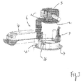
- FIG 1 an exploded view of an insert according to the present invention.
- the insert comprises a tube section 1, an end cover 2, an electrical connection box 3, flexible and/or resilient expansion means 4, a double hinge construction 5 which in this embodiment is provided with a transformer 6 as well as a cover part 7.
- the cover part is designed to be mounted once the entire insert and its connection have been installed through an aperture in an element such that the cover part 7 will cover the aperture and make an aesthetically pleasing finish finish around the insert.
- the tube section 1 may be cylindrical, but not necessarily, and is in this embodiment provided with an opening in either end which will be explained with reference to the following figures.
- the double hinge mechanism 5 is provided with two pivot points 8, 9 such that the hinge flanges 10, 11 may relatively pivot such that the flange 11 may be put in a position where it extends in the same line as the tube section 1. In this manner it becomes possible to install the entire installation through an aperture in an element which is of a size corresponding to the outside diameter of the tube section 1.
- fastening means include a resilient member 12 which may be moved outside the periphery of the tube section 1 and into engagement with the backside of the plate member (not illustrated).
- the end cover 2 is provided with a number of flanges 13, 14 which may be interfitted with corresponding recesses provided at the top end 15 of the tube section such that after having placed the flange members 13, 14 inside the apertures provided in the end of the tube section 1 and twisting the end cover 2 a strong connection is established between the end cover 2 and the tube section 1.
- the flange 11 may advantageously be provided with half circle shaped protrusions 20. These serve to avoid the flange being entangled in wires, cables or the like placed on the back side of the member into which the insert is mounted. Also when the insert is mounted in ceilings made from wood, the protrusions 20 will act as runners, helping the flange 11 and thereby the insert, passing gaps, grooves and the like which may be present on the surface.
- connection box may be adapted to house 12, 24, 110, 220 or any other voltage installations and is in this embodiment provided with legs 25 such that a distance is maintained between the end cover 2 and the connection box 3 such that the heat developed by the light fixture does not transfer immediately to the electrical connections.
- the cover plate 7 is arranged inside the tube section (not illustrated) by resilient means in the shape of springs 26 such that variations in the plate thickness "a" may be compensated for by adjusting the distance the cover plate 7 is inserted into the tube section 1.
- ridges and grooves may be provided in order to fasten the springs 26 in the desired position.
- the upper end of the spring 26 may be provided with a point.
- the ridges/grooves provided on the inside of the tube section may be shaped as a tread, such that the point of the springs may engage the tread.
- socket means are arranged for inserting a desirable light fixture, for example a socket means of the type GU 10 suitable for providing fixture for halogen lights or standard 220 volt sockets.
Abstract
Description
- The present invention relates to an insert suitable for being placed in a wall, ceiling or other element.
- When mounting electrical equipment in wall, ceilings or other elements such as for example kitchen cupboards, book cases, shelves and the like, it is customary to arrange a box inside a cavity made in said element. The electrical wiring is usually led via appropriate piping systems to the connection boxes whereafter electrical equipment such as lamps, switches etc. are arranged, for example as a cover for the electrical connection box. Especially for lamps, the socket is usually arranged in a wire extending through an aperture in the lid of the electrical connection box, such that there is a physical distance between the electrical connection box and the socket for the lamp. For other types of lamps, especially for the so-called built-in spotlights, a ceiling spaced from the lower side of the horizontal division between two floor is provided. In the ceiling holes are drilled wherein the spots are arranged. On top of the ceiling the wiring is led to connection boxes attached to the underside of the horizontal division, whereby the built-in spots may be supplied with electricity. An example of such a connection box is disclosed in
US6168299 . - In buildings where a lowered ceiling cannot be provided, special implements may be inserted on the backside of the ceiling in order to accommodate the built-in spotlights. A number of factors must be taken into consideration when providing such a construction. Among others, the insulation placed immediately adjacent the ceiling as well as the humidity membrane has to be taken into consideration and appropriate measures taken in order for the humidity membrane to stay intact, and also for the insulation to be arranged properly around the build-in spotlight holder.
- An additional problem concerning built-in spotlights in particular is generation of heat from halogen light sources which are predominant in the interior design, especially of stores and shops. In order to minimise the fire hazard, it is desirable to make sure that the temperature behind the halogen light source does not reach a level where ignition of combustible materials in the vicinity of the built-in halogen spot becomes a real risk. Usually, manufacturers of the halogen built-in spotlight devices advise that combustible materials should not be placed within 50 cm of such a device in order to avoid fire hazard. For some suppliers of electrical equipment, the corresponding requirements is that the temperature in the vicinity of the electrical equipment should not be allowed to rise above 90° C in order not to damage the electrical equipment and thereby rendering the electrical equipment the source of a fire hazard.
- A prior art device comprising means for cooling the electrical equipment is known from
US5664872 . This device comprises two sections with are to be coupled such that first the electrical connections are completed and afterwards a fan unit is fitted to the connection box, whereby activation of the fan causes air to pass by the electrical installation. The connection box is adapted to be screwed into for example a ceiling, and then the light fixture will be mounted by means of a collar which collar is to be snap fitted onto the flange of the connection box, in order to provide the finishing touch necessary for this kind of installations when installed into an interior decoration scheme. The installation requires a number of parts, and furthermore once the connection box and the electrical connections are arranged it is impossible to access the fan unit from below the ceiling. Thereby cleaning and maintenance of the unit is severely hampered as a complete demounting of the unit is required in order to gain access to the unit. - The prior art devices are also all designed for use with only one particular type of light source in that each prior art device is supplied with one particular type of socket. Furthermore, for a number of applications it is necessary to have the device as such approved by the national authority for electrical installations, and most manufactures are therefore attempts to obtain approval for a series of prior art devices suitable for different light sources.
- A lighting device for recessed mounting comprising all the technical features set forth in the preamble of the claim 1 is disclosed in
US 6 116 758 . - It is consequently an object of the present invention to provide an insert suitable for being placed in a wall, ceiling, furniture element or other element wherein an electrical installation means such as a lamp socket or the like may be fitted, without this insert causing any of the problems or risks as mentioned above. Also the insert shall be adaptable to include various light sources, in a standardized manner.
- The present invention addresses this problem by providing an insert of the kind mentioned above wherein the insert comprises a housing, where said housing comprises a tube section, an end cover, where said end cover and one end of the tube section is provided with releasable assembly means, and where the opposite end of the tube section is open, where said insert comprises means arranged outside of the tube section, which means are expandable outside the inserts' outer periphery, and where socket means and electrical connection means are provided in said end cover.
- By providing separate elements, i.e. a tube section and an end cover, it becomes possible to use the tube section as a standard element for mounting a variety of different types of light fixtures in that the end cover which comprises the socket and the electrical connection means may be selected according to the desired light source. In this manner it becomes possible to standardize the mounting of the inserts regardless of which type of light source is desirable at that particular position. The different types of light sources are also in most instances necessary to have different power sources and therefore, by using a standardized tube section means the physical mounting in the element, for example a ceiling, wall or the like, may be carried out routinely, and the electrical connection means may also be carried out in a routine manner regardless of the power supply provided at that particular position.
- The fastening between the end cover and the tube section may for example be a so-called bayonet connection where flanges are provided along part of the periphery extending from the end cover where the part flanges may be inserted into suitable slits provided at the end of the tube section and by turning the end cover relative to the tube section, the flanges will engage the end of the tube section thereby safely and securely holding the tube section in relation to the end cover. Optionally adhesives, threads, snap-arrangements between the two parts or other means of fastening may be provided between the two elements.
- Furthermore, a double hinge is provided, pivotably fastenable to the end cover or to the tube section, where the hinge comprises flange means for fastening electrical components such as one or more of the following: transformer, electrical switch, remote control circuitry, cooling and/or ventilation means.
- In a further advantageous embodiment the end cover is provided on the side facing away from the interior of the tube section, with an electrical connection box, which box may be selected according to the power, current, effect or light source needed.
- Typically, the authorities will impose requirements on the means for protecting the surroundings against the possibility of electrical shocks, in particular where connections are provided in wiring. For this purpose, having a standardized connection box suitable and manufactured specifically for being attached to the end cover, it may be possible to use a standard connection box with any type of connection such that a safe and approved construction may be provided by using standard elements making up the insert according to the present invention.
- As the insert provides the possibility of mounting the entire light fixture from the side from which the light is supposed to be visible, only an aperture slightly larger than the insert is desirable. For this reason all components need to pass through this aperture which is related to the installation as such. The double hinge mechanism provides for the possibility of having elongated elements such as for example a transformer or the like mounted on the hinge member which may be passed through the opening in the element prior to inserting the insert. The hinge mechanism will thereafter make sure that the components such as for example an electrical transformer, an electrical switch remote control circuitry, cooling and/or ventilation means are positioned immediately adjacent the back side of the element such that the overall construction height is kept at a minimum.
- It is also possible to arranged the fastening of the double hinge on the tube section.
- Naturally, the electrical components mentioned above do not limit the number or types of electrical components which are suitable to be arranged in connection with the double hinge.
- The provision means expandable outside the insert's outer periphery, for example in the shape of resilient means for fastening the insert, does not necessarily need special tools, as in some embodiments the resilient means will be deflected when placing the insert and after the insert has reached its final position the resilient means will flick back into the original position and in this manner maintain the insert in position.
- Furthermore, by providing resilient means, whether or not in the shape of spring like elements or as integrated deformable elements or sections in the insert, a firm and furthermore adaptable fastening method is provided. As the circumstances concerning the building components may vary from installation site to installation site, the advantageous provision of resilient means, i.e. adaptable fastening means, provides the possibility for reliable mounting of the insert in various materials and various circumstances. Thereby the risk of errors during installation is greatly reduced.
- In a further advantageous embodiment of the insert according the present invention, a ventilation means is arranged at the end of the insert opposite the aperture.
By arranging the ventilation means in the end of the insert opposite to where the aperture is arranged, the interior of the insert is completely free and therefore any electrical installation may be installed without any interference from the ventilating means. - In a further advantageous embodiment, the end of the insert comprises one or more apertures for letting air in or out of the insert. In order for the insert to be able to compensate for the differences in pressure arising due to the ventilating means, apertures may be provided such that the inside of the insert is in communication with the ambient air.
- In a further advantageous embodiment of the invention, the ventilations means is a ventilator comprising a fan and that optionally the current supply to the electrical installation also supplies current to the ventilation means.
- In addition to a fan cooling ribs, for example aluminium ribs, may be provided. Although condensation often occurs due to the cold aluminium surfaces, the air current created by the fan will transport away any moisture, whereby condensation problems are avoided.
- For low voltage installations such as for example 12 or 24 volt, it is possible to buy fans with a very low power consumption which will be able to provide a sufficient air current around the electrical installation in order to provide a cooling effect. The power consumption is negligible in comparison to the power consumption by the light sources and, additionally, the extra heat generated by the fan is also insignificant in comparison to the cooling air current which may be led through the inside of the insert. For other voltages such as 110 volt or 230 volt, either appropriate fan means or a transformation means may be inserted in the circuit such that the fan is provided with the appropriate current and voltage. By this arrangement it is foreseen that no extra installations or actions are necessary in order to be able to provide the ventilation means with a power supply in that the insert is especially adapted to use with electrical installations and therefore means for providing the electrical power will be present in the insert and thereby available for powering the fan.
- In a further advantageous embodiment the side of the end facing away from the aperture is supplied with distance keeping means as for example legs, protrusions, netting basket or the like. In instances where the insert according to the invention is installed in ceilings where the ceiling construction comprises the visible ceiling cladding behind which a humidity barrier is arranged, behind which the insulation is arranged, for example a soft glass wool, the insert is provided with distance keeping means such that it will be possible to make air available to the fan in order to create the cooling air stream down through the insert in order to cool the electrical installation provided inside the insert.
- The distance keeping means may also comprise a filter such that dust and other particles are not transported into the room through the insert.
- By arranging a fan, for example a low voltage fan comparable to the fans commonly used in order to cool personal computers, an advantageous embodiment may be achieved. These types of fans have a projected life expectancy of up till 200,000 hours at constant load at 70° C. Tests with the present invention have shown that in a set-up where a 35 W halogen light source of the Osram Decostar type was arranged inside the insert, the temperature above the light source, where the light source was connected to the wiring, reached about and stabilised at 91 °C for the said 35 W halogen light source. By installing a fan of the type mentioned above used in personal computers, the temperature immediately adjacent the light source was reduced to 54.6° C and around the caballing the temperature was measured and stabilised around 32° C. The temperatures measured were, after the initial heat-up period, stable for the duration of the test which lasted more than four hours.
- The lowering of the temperature has a number of advantageous effects. First of all, the life expectancy of the light source may be increased and at the same time the fire hazard immediately adjacent the installation is reduced dramatically. Furthermore, by arranging the fan such that the air current is directed into the room where the light is emitted, the heat produced by the light source and the fan is ventilated into the room and may therefore be used for heating purposes. Furthermore, as warm air is lighter than cold air, the warm air produced in order to provide a comfortable temperature in the living zone may be lowered in that the light source, due to the fans, will create a circulation of the air immediately adjacent the ceiling such that the warm air gathering along the ceiling will be forced downwards due to the air streams created by the cooling fans.
- In a still further advantageous embodiment of the invention the insert is provided with means for attaching the electrical installation means, and that further means are provided for allowing the air stream created by the ventilation means to pass the electrical installation means.
- The invention will now be explained in detail with respect to the accompanying drawing, wherein
- fig. 1
- shows a schematic presentation of an insert in exploded view,
- fig. 2
- shows a schematic presentation of an insert, assembled,
- fig. 3
- shows a cross-section through an insert in its mounted position,
- In
figure 1 is illustrated an exploded view of an insert according to the present invention. The insert comprises a tube section 1, anend cover 2, an electrical connection box 3, flexible and/or resilient expansion means 4, adouble hinge construction 5 which in this embodiment is provided with atransformer 6 as well as acover part 7. - The cover part is designed to be mounted once the entire insert and its connection have been installed through an aperture in an element such that the
cover part 7 will cover the aperture and make an aesthetically pleasing finish finish around the insert. - The tube section 1 may be cylindrical, but not necessarily, and is in this embodiment provided with an opening in either end which will be explained with reference to the following figures. The
double hinge mechanism 5 is provided with twopivot points 8, 9 such that thehinge flanges flange 11 may be put in a position where it extends in the same line as the tube section 1. In this manner it becomes possible to install the entire installation through an aperture in an element which is of a size corresponding to the outside diameter of the tube section 1. - In order to fasten the tube section 1 on the backside of the element, flexible and/or resilient expansion means 4 are provided where the fastening means include a
resilient member 12 which may be moved outside the periphery of the tube section 1 and into engagement with the backside of the plate member (not illustrated). - The
end cover 2 is provided with a number offlanges 13, 14 which may be interfitted with corresponding recesses provided at thetop end 15 of the tube section such that after having placed theflange members 13, 14 inside the apertures provided in the end of the tube section 1 and twisting the end cover 2 a strong connection is established between theend cover 2 and the tube section 1. - When assembling the elements described above with reference to
figure 1 an insert as illustrated with reference tofigure 2 will be the result. In this embodiment the number "18" written on the body of the tube section 1 illustrates the thickness of the plate member into which the insert is to be mounted. With this configuration it is ensured that thetransformer 6 will be positioned in a substantially horizontal position. This may be adjusted by the length of theflange 10 or the extent of theprotrusions 20 arranged on theother flange 11. - The
flange 11 may advantageously be provided with half circle shapedprotrusions 20. These serve to avoid the flange being entangled in wires, cables or the like placed on the back side of the member into which the insert is mounted. Also when the insert is mounted in ceilings made from wood, theprotrusions 20 will act as runners, helping theflange 11 and thereby the insert, passing gaps, grooves and the like which may be present on the surface. - Turning to the flexible and/or resilient expansion means 4 it may be seen that by moving the
member 21 downwards theend 22 of theresilient member 12 will due to the interaction with the fastening means 24 be made to project outside the periphery of the tube section 1 such that it is possible to engage the backside of the plate member into which the insert is to be mounted. - In
figure 3 is illustrated an embodiment where the tube section has been removed such that only thecover 7, thehinge 5, thetransformer 6, theend cover 2, the flexible and/or resilient expansion means 4 and the connection box 3 are visible. The connection box may be adapted tohouse legs 25 such that a distance is maintained between theend cover 2 and the connection box 3 such that the heat developed by the light fixture does not transfer immediately to the electrical connections. - As may further be seen, the
cover plate 7 is arranged inside the tube section (not illustrated) by resilient means in the shape ofsprings 26 such that variations in the plate thickness "a" may be compensated for by adjusting the distance thecover plate 7 is inserted into the tube section 1. Inside the tube section ridges and grooves may be provided in order to fasten thesprings 26 in the desired position.
The upper end of thespring 26 may be provided with a point. The ridges/grooves provided on the inside of the tube section may be shaped as a tread, such that the point of the springs may engage the tread. By rotating the cover plate, the point will travel upwards or downwards depending on the threads orientation and the direction of rotation, whereby it becomes possible to adjust the coverplate's position accurately, relative to the surface into which the insert is mounted. - On the underside of the
end cover member 2, (when assembled that is on the inside of the tube section, socket means are arranged for inserting a desirable light fixture, for example a socket means of thetype GU 10 suitable for providing fixture for halogen lights or standard 220 volt sockets.
Claims (2)
- Insert suitable for being mounted in a wall, ceiling, piece of furniture or other element, wherein the insert comprises a housing, where said housing comprises a tube section (1), an end cover (2), where said end cover (2) and one end of the tube section (1) is provided with releasable assembly means, and where the opposite end of the tube section (1) is open, where said insert comprises means (4) arranged outside of the tube section (1), which means (4) are expandable outside the inserts' outer periphery, and where socket means and electrical connection means are provided in said end cover (2) characterized in that a double hinge (8,9) is provided, pivotably fastenable to the end cover (2) or the tube section (1), where the hinge (8,9) comprises flange means (11) for fastening electrical components (6) such as one or more of the following: transformer, electrical switch, remote control circuitry, cooling and/or ventilation means.
- Insert according to claim 1 wherein the end cover (2) is provided on the side facing away from the interior of the tube section (1), with an electrical connection box (3), which box (3) may be selected according to the power, current, effect or light source need.
Priority Applications (2)
| Application Number | Priority Date | Filing Date | Title |
|---|---|---|---|
| PL09168398T PL2157370T3 (en) | 2008-08-22 | 2009-08-21 | Adaptable insert |
| DKBA201000167U DK201000167U4 (en) | 2008-08-22 | 2010-09-02 | Built-in box for installation in a wall, ceiling or other element |
Applications Claiming Priority (1)
| Application Number | Priority Date | Filing Date | Title |
|---|---|---|---|
| DKPA200801151 | 2008-08-22 |
Publications (3)
| Publication Number | Publication Date |
|---|---|
| EP2157370A2 EP2157370A2 (en) | 2010-02-24 |
| EP2157370A3 EP2157370A3 (en) | 2010-10-13 |
| EP2157370B1 true EP2157370B1 (en) | 2012-02-15 |
Family
ID=41119953
Family Applications (1)
| Application Number | Title | Priority Date | Filing Date |
|---|---|---|---|
| EP09168398A Not-in-force EP2157370B1 (en) | 2008-08-22 | 2009-08-21 | Adaptable insert |
Country Status (4)
| Country | Link |
|---|---|
| EP (1) | EP2157370B1 (en) |
| AT (1) | ATE545828T1 (en) |
| DK (2) | DK2157370T3 (en) |
| PL (1) | PL2157370T3 (en) |
Families Citing this family (3)
| Publication number | Priority date | Publication date | Assignee | Title |
|---|---|---|---|---|
| EP2630404A1 (en) | 2010-10-20 | 2013-08-28 | Daxtor APS | An insert |
| EP2518400A1 (en) | 2011-04-14 | 2012-10-31 | Daxtor APS | Recessed mounting box with locking ring |
| DK201100177U4 (en) | 2011-12-05 | 2013-03-22 | Daxtor Aps | Mounting brackets for use in mounting equipment for lighting equipment |
Family Cites Families (11)
| Publication number | Priority date | Publication date | Assignee | Title |
|---|---|---|---|---|
| US3700885A (en) * | 1970-10-01 | 1972-10-24 | Air King Corp | Architectural light and adjustment means therefor |
| IT8311958V0 (en) * | 1983-12-09 | 1983-12-09 | Targetti Sankey Spa | BUILT-IN LUME COMPLEX, WITH TUBULAR BODY SUITABLE FOR WELCOMING IN THE HEADQUARTERS |
| US4870549A (en) * | 1987-08-26 | 1989-09-26 | Siemens Aktiengesellschaft | Built-in ceiling light |
| GB9324030D0 (en) | 1993-11-23 | 1994-01-12 | Smiths Industries Plc | Assemblies |
| US6116758A (en) * | 1998-03-31 | 2000-09-12 | Lin; Michael | light inlay for various halogen light bulbs, lagging illumination and all necessary accessories |
| US6168299B1 (en) | 1999-04-30 | 2001-01-02 | Ellis Yan | Energy efficient recessed lighting fixture |
| US6655813B1 (en) * | 2002-01-07 | 2003-12-02 | Genlyte Thomas Group Llc | Multi-function luminaire |
| CA2373874C (en) * | 2002-02-28 | 2007-10-02 | Canlyte Inc. | Light fixture assembly |
| ITMI20030994A1 (en) * | 2003-05-20 | 2004-11-21 | Ivela S P A | SUPPORT FRAME FOR RECESSED LIGHTING LUMINAIRE. |
| CA2577753C (en) * | 2006-02-17 | 2014-09-23 | Canlyte Inc. | Recessed lighting fixture |
| GB2435722A (en) * | 2006-03-03 | 2007-09-05 | James Christopher Patr Mcenery | Disconnectable electrical fixture |
-
2009
- 2009-08-21 PL PL09168398T patent/PL2157370T3/en unknown
- 2009-08-21 EP EP09168398A patent/EP2157370B1/en not_active Not-in-force
- 2009-08-21 AT AT09168398T patent/ATE545828T1/en active
- 2009-08-21 DK DK09168398.7T patent/DK2157370T3/en active
-
2010
- 2010-09-02 DK DKBA201000167U patent/DK201000167U4/en not_active IP Right Cessation
Also Published As
| Publication number | Publication date |
|---|---|
| DK201000167U1 (en) | 2010-09-24 |
| EP2157370A2 (en) | 2010-02-24 |
| EP2157370A3 (en) | 2010-10-13 |
| DK201000167U4 (en) | 2010-12-10 |
| PL2157370T3 (en) | 2012-07-31 |
| ATE545828T1 (en) | 2012-03-15 |
| DK2157370T3 (en) | 2012-05-29 |
Similar Documents
| Publication | Publication Date | Title |
|---|---|---|
| US7607935B2 (en) | Insert with ventilation | |
| US9188132B1 (en) | 110 CFM bath fan with and without light | |
| US8636387B1 (en) | Surface-mounted lighting system | |
| US9752765B2 (en) | Fire rated recessed lighting assembly | |
| US8182116B2 (en) | Lighting fixture with recessed baffle trim unit | |
| US6350046B1 (en) | Light fixture | |
| US10907843B2 (en) | Ventilating system and method | |
| US7824080B2 (en) | Housing for a recessed light fixture | |
| US7874711B2 (en) | Surface-mounted lighting system | |
| US20100136897A1 (en) | ventilation cover with a light source | |
| US10508445B2 (en) | Housing apparatus for installation of ceiling or wall-mounted electrical appliances | |
| US9506611B2 (en) | Recessed luminaire with shuttle mechanism for access to electrical components | |
| CN112350254A (en) | System and method for securing power and communication cables and related hardware within crown molding | |
| EP2157370B1 (en) | Adaptable insert | |
| KR200407104Y1 (en) | Raceway with integrated luminaire | |
| US7329023B2 (en) | Low-power illumination apparatus | |
| US20060109660A1 (en) | Light fixture | |
| EP2581645B1 (en) | Modular spotlight | |
| US7484979B2 (en) | Hub assembly | |
| GB2490956A (en) | Lighting unit with demountable lamp housing, fireproofing and removable waterproofing structure | |
| US20080198608A1 (en) | Low-Power Illumination Apparatus | |
| KR200450750Y1 (en) | duct frame fixing structure of diffuser for air condition | |
| WO1998033009A1 (en) | Light fixture | |
| KR102600499B1 (en) | Freeze protection heater for toilet | |
| KR100687603B1 (en) | Electric terminal box for ceiling of apartment house |
Legal Events
| Date | Code | Title | Description |
|---|---|---|---|
| PUAI | Public reference made under article 153(3) epc to a published international application that has entered the european phase |
Free format text: ORIGINAL CODE: 0009012 |
|
| AK | Designated contracting states |
Kind code of ref document: A2 Designated state(s): AT BE BG CH CY CZ DE DK EE ES FI FR GB GR HR HU IE IS IT LI LT LU LV MC MK MT NL NO PL PT RO SE SI SK SM TR |
|
| AX | Request for extension of the european patent |
Extension state: AL BA RS |
|
| PUAL | Search report despatched |
Free format text: ORIGINAL CODE: 0009013 |
|
| AK | Designated contracting states |
Kind code of ref document: A3 Designated state(s): AT BE BG CH CY CZ DE DK EE ES FI FR GB GR HR HU IE IS IT LI LT LU LV MC MK MT NL NO PL PT RO SE SI SK SM TR |
|
| AX | Request for extension of the european patent |
Extension state: AL BA RS |
|
| 17P | Request for examination filed |
Effective date: 20110413 |
|
| GRAP | Despatch of communication of intention to grant a patent |
Free format text: ORIGINAL CODE: EPIDOSNIGR1 |
|
| RIC1 | Information provided on ipc code assigned before grant |
Ipc: F21V 21/04 20060101AFI20110801BHEP Ipc: F21V 23/02 20060101ALI20110801BHEP |
|
| GRAS | Grant fee paid |
Free format text: ORIGINAL CODE: EPIDOSNIGR3 |
|
| GRAA | (expected) grant |
Free format text: ORIGINAL CODE: 0009210 |
|
| AK | Designated contracting states |
Kind code of ref document: B1 Designated state(s): AT BE BG CH CY CZ DE DK EE ES FI FR GB GR HR HU IE IS IT LI LT LU LV MC MK MT NL NO PL PT RO SE SI SK SM TR |
|
| REG | Reference to a national code |
Ref country code: CH Ref legal event code: EP Ref country code: GB Ref legal event code: FG4D |
|
| REG | Reference to a national code |
Ref country code: IE Ref legal event code: FG4D |
|
| REG | Reference to a national code |
Ref country code: AT Ref legal event code: REF Ref document number: 545828 Country of ref document: AT Kind code of ref document: T Effective date: 20120315 |
|
| REG | Reference to a national code |
Ref country code: DE Ref legal event code: R096 Ref document number: 602009005328 Country of ref document: DE Effective date: 20120419 |
|
| REG | Reference to a national code |
Ref country code: CH Ref legal event code: NV Representative=s name: FIAMMENGHI-FIAMMENGHI |
|
| REG | Reference to a national code |
Ref country code: DK Ref legal event code: T3 |
|
| REG | Reference to a national code |
Ref country code: NL Ref legal event code: T3 |
|
| REG | Reference to a national code |
Ref country code: SE Ref legal event code: TRGR |
|
| REG | Reference to a national code |
Ref country code: NO Ref legal event code: T2 Effective date: 20120215 |
|
| LTIE | Lt: invalidation of european patent or patent extension |
Effective date: 20120215 |
|
| PG25 | Lapsed in a contracting state [announced via postgrant information from national office to epo] |
Ref country code: HR Free format text: LAPSE BECAUSE OF FAILURE TO SUBMIT A TRANSLATION OF THE DESCRIPTION OR TO PAY THE FEE WITHIN THE PRESCRIBED TIME-LIMIT Effective date: 20120215 Ref country code: IS Free format text: LAPSE BECAUSE OF FAILURE TO SUBMIT A TRANSLATION OF THE DESCRIPTION OR TO PAY THE FEE WITHIN THE PRESCRIBED TIME-LIMIT Effective date: 20120615 Ref country code: LT Free format text: LAPSE BECAUSE OF FAILURE TO SUBMIT A TRANSLATION OF THE DESCRIPTION OR TO PAY THE FEE WITHIN THE PRESCRIBED TIME-LIMIT Effective date: 20120215 |
|
| REG | Reference to a national code |
Ref country code: PL Ref legal event code: T3 |
|
| PG25 | Lapsed in a contracting state [announced via postgrant information from national office to epo] |
Ref country code: FI Free format text: LAPSE BECAUSE OF FAILURE TO SUBMIT A TRANSLATION OF THE DESCRIPTION OR TO PAY THE FEE WITHIN THE PRESCRIBED TIME-LIMIT Effective date: 20120215 Ref country code: GR Free format text: LAPSE BECAUSE OF FAILURE TO SUBMIT A TRANSLATION OF THE DESCRIPTION OR TO PAY THE FEE WITHIN THE PRESCRIBED TIME-LIMIT Effective date: 20120516 Ref country code: BE Free format text: LAPSE BECAUSE OF FAILURE TO SUBMIT A TRANSLATION OF THE DESCRIPTION OR TO PAY THE FEE WITHIN THE PRESCRIBED TIME-LIMIT Effective date: 20120215 Ref country code: PT Free format text: LAPSE BECAUSE OF FAILURE TO SUBMIT A TRANSLATION OF THE DESCRIPTION OR TO PAY THE FEE WITHIN THE PRESCRIBED TIME-LIMIT Effective date: 20120615 Ref country code: LV Free format text: LAPSE BECAUSE OF FAILURE TO SUBMIT A TRANSLATION OF THE DESCRIPTION OR TO PAY THE FEE WITHIN THE PRESCRIBED TIME-LIMIT Effective date: 20120215 |
|
| PG25 | Lapsed in a contracting state [announced via postgrant information from national office to epo] |
Ref country code: CY Free format text: LAPSE BECAUSE OF FAILURE TO SUBMIT A TRANSLATION OF THE DESCRIPTION OR TO PAY THE FEE WITHIN THE PRESCRIBED TIME-LIMIT Effective date: 20120215 |
|
| PG25 | Lapsed in a contracting state [announced via postgrant information from national office to epo] |
Ref country code: RO Free format text: LAPSE BECAUSE OF FAILURE TO SUBMIT A TRANSLATION OF THE DESCRIPTION OR TO PAY THE FEE WITHIN THE PRESCRIBED TIME-LIMIT Effective date: 20120215 Ref country code: CZ Free format text: LAPSE BECAUSE OF FAILURE TO SUBMIT A TRANSLATION OF THE DESCRIPTION OR TO PAY THE FEE WITHIN THE PRESCRIBED TIME-LIMIT Effective date: 20120215 Ref country code: EE Free format text: LAPSE BECAUSE OF FAILURE TO SUBMIT A TRANSLATION OF THE DESCRIPTION OR TO PAY THE FEE WITHIN THE PRESCRIBED TIME-LIMIT Effective date: 20120215 Ref country code: SI Free format text: LAPSE BECAUSE OF FAILURE TO SUBMIT A TRANSLATION OF THE DESCRIPTION OR TO PAY THE FEE WITHIN THE PRESCRIBED TIME-LIMIT Effective date: 20120215 |
|
| PG25 | Lapsed in a contracting state [announced via postgrant information from national office to epo] |
Ref country code: SK Free format text: LAPSE BECAUSE OF FAILURE TO SUBMIT A TRANSLATION OF THE DESCRIPTION OR TO PAY THE FEE WITHIN THE PRESCRIBED TIME-LIMIT Effective date: 20120215 Ref country code: IT Free format text: LAPSE BECAUSE OF FAILURE TO SUBMIT A TRANSLATION OF THE DESCRIPTION OR TO PAY THE FEE WITHIN THE PRESCRIBED TIME-LIMIT Effective date: 20120215 |
|
| PLBE | No opposition filed within time limit |
Free format text: ORIGINAL CODE: 0009261 |
|
| STAA | Information on the status of an ep patent application or granted ep patent |
Free format text: STATUS: NO OPPOSITION FILED WITHIN TIME LIMIT |
|
| 26N | No opposition filed |
Effective date: 20121116 |
|
| REG | Reference to a national code |
Ref country code: DE Ref legal event code: R097 Ref document number: 602009005328 Country of ref document: DE Effective date: 20121116 |
|
| PG25 | Lapsed in a contracting state [announced via postgrant information from national office to epo] |
Ref country code: MC Free format text: LAPSE BECAUSE OF NON-PAYMENT OF DUE FEES Effective date: 20120831 |
|
| PG25 | Lapsed in a contracting state [announced via postgrant information from national office to epo] |
Ref country code: ES Free format text: LAPSE BECAUSE OF FAILURE TO SUBMIT A TRANSLATION OF THE DESCRIPTION OR TO PAY THE FEE WITHIN THE PRESCRIBED TIME-LIMIT Effective date: 20120526 |
|
| REG | Reference to a national code |
Ref country code: IE Ref legal event code: MM4A |
|
| PG25 | Lapsed in a contracting state [announced via postgrant information from national office to epo] |
Ref country code: IE Free format text: LAPSE BECAUSE OF NON-PAYMENT OF DUE FEES Effective date: 20120821 Ref country code: BG Free format text: LAPSE BECAUSE OF FAILURE TO SUBMIT A TRANSLATION OF THE DESCRIPTION OR TO PAY THE FEE WITHIN THE PRESCRIBED TIME-LIMIT Effective date: 20120515 |
|
| PG25 | Lapsed in a contracting state [announced via postgrant information from national office to epo] |
Ref country code: MT Free format text: LAPSE BECAUSE OF FAILURE TO SUBMIT A TRANSLATION OF THE DESCRIPTION OR TO PAY THE FEE WITHIN THE PRESCRIBED TIME-LIMIT Effective date: 20120215 |
|
| PG25 | Lapsed in a contracting state [announced via postgrant information from national office to epo] |
Ref country code: TR Free format text: LAPSE BECAUSE OF FAILURE TO SUBMIT A TRANSLATION OF THE DESCRIPTION OR TO PAY THE FEE WITHIN THE PRESCRIBED TIME-LIMIT Effective date: 20120215 |
|
| PG25 | Lapsed in a contracting state [announced via postgrant information from national office to epo] |
Ref country code: LU Free format text: LAPSE BECAUSE OF NON-PAYMENT OF DUE FEES Effective date: 20120821 Ref country code: SM Free format text: LAPSE BECAUSE OF FAILURE TO SUBMIT A TRANSLATION OF THE DESCRIPTION OR TO PAY THE FEE WITHIN THE PRESCRIBED TIME-LIMIT Effective date: 20120215 |
|
| PG25 | Lapsed in a contracting state [announced via postgrant information from national office to epo] |
Ref country code: HU Free format text: LAPSE BECAUSE OF FAILURE TO SUBMIT A TRANSLATION OF THE DESCRIPTION OR TO PAY THE FEE WITHIN THE PRESCRIBED TIME-LIMIT Effective date: 20090821 |
|
| PGFP | Annual fee paid to national office [announced via postgrant information from national office to epo] |
Ref country code: CH Payment date: 20140827 Year of fee payment: 6 Ref country code: NL Payment date: 20140826 Year of fee payment: 6 |
|
| PGFP | Annual fee paid to national office [announced via postgrant information from national office to epo] |
Ref country code: PL Payment date: 20140806 Year of fee payment: 6 Ref country code: AT Payment date: 20140801 Year of fee payment: 6 |
|
| PG25 | Lapsed in a contracting state [announced via postgrant information from national office to epo] |
Ref country code: MK Free format text: LAPSE BECAUSE OF FAILURE TO SUBMIT A TRANSLATION OF THE DESCRIPTION OR TO PAY THE FEE WITHIN THE PRESCRIBED TIME-LIMIT Effective date: 20120215 |
|
| REG | Reference to a national code |
Ref country code: FR Ref legal event code: PLFP Year of fee payment: 7 |
|
| PGFP | Annual fee paid to national office [announced via postgrant information from national office to epo] |
Ref country code: NO Payment date: 20150827 Year of fee payment: 7 Ref country code: DE Payment date: 20150827 Year of fee payment: 7 Ref country code: DK Payment date: 20150825 Year of fee payment: 7 Ref country code: GB Payment date: 20150827 Year of fee payment: 7 |
|
| PGFP | Annual fee paid to national office [announced via postgrant information from national office to epo] |
Ref country code: SE Payment date: 20150827 Year of fee payment: 7 Ref country code: FR Payment date: 20150817 Year of fee payment: 7 |
|
| REG | Reference to a national code |
Ref country code: CH Ref legal event code: PL |
|
| REG | Reference to a national code |
Ref country code: AT Ref legal event code: MM01 Ref document number: 545828 Country of ref document: AT Kind code of ref document: T Effective date: 20150821 |
|
| PG25 | Lapsed in a contracting state [announced via postgrant information from national office to epo] |
Ref country code: CH Free format text: LAPSE BECAUSE OF NON-PAYMENT OF DUE FEES Effective date: 20150831 Ref country code: LI Free format text: LAPSE BECAUSE OF NON-PAYMENT OF DUE FEES Effective date: 20150831 |
|
| REG | Reference to a national code |
Ref country code: NL Ref legal event code: MM Effective date: 20150901 |
|
| PG25 | Lapsed in a contracting state [announced via postgrant information from national office to epo] |
Ref country code: AT Free format text: LAPSE BECAUSE OF NON-PAYMENT OF DUE FEES Effective date: 20150821 |
|
| PG25 | Lapsed in a contracting state [announced via postgrant information from national office to epo] |
Ref country code: NL Free format text: LAPSE BECAUSE OF NON-PAYMENT OF DUE FEES Effective date: 20150901 |
|
| PG25 | Lapsed in a contracting state [announced via postgrant information from national office to epo] |
Ref country code: PL Free format text: LAPSE BECAUSE OF NON-PAYMENT OF DUE FEES Effective date: 20150821 |
|
| REG | Reference to a national code |
Ref country code: DE Ref legal event code: R119 Ref document number: 602009005328 Country of ref document: DE |
|
| REG | Reference to a national code |
Ref country code: DK Ref legal event code: EBP Effective date: 20160831 Ref country code: NO Ref legal event code: MMEP |
|
| REG | Reference to a national code |
Ref country code: SE Ref legal event code: EUG |
|
| GBPC | Gb: european patent ceased through non-payment of renewal fee |
Effective date: 20160821 |
|
| PG25 | Lapsed in a contracting state [announced via postgrant information from national office to epo] |
Ref country code: SE Free format text: LAPSE BECAUSE OF NON-PAYMENT OF DUE FEES Effective date: 20160822 Ref country code: NO Free format text: LAPSE BECAUSE OF NON-PAYMENT OF DUE FEES Effective date: 20160831 |
|
| REG | Reference to a national code |
Ref country code: FR Ref legal event code: ST Effective date: 20170428 |
|
| PG25 | Lapsed in a contracting state [announced via postgrant information from national office to epo] |
Ref country code: FR Free format text: LAPSE BECAUSE OF NON-PAYMENT OF DUE FEES Effective date: 20160831 Ref country code: DE Free format text: LAPSE BECAUSE OF NON-PAYMENT OF DUE FEES Effective date: 20170301 Ref country code: GB Free format text: LAPSE BECAUSE OF NON-PAYMENT OF DUE FEES Effective date: 20160821 Ref country code: DK Free format text: LAPSE BECAUSE OF NON-PAYMENT OF DUE FEES Effective date: 20160831 |