EP2157296A1 - Engine, vehicle, boat, and engine exhaust method - Google Patents
Engine, vehicle, boat, and engine exhaust method Download PDFInfo
- Publication number
- EP2157296A1 EP2157296A1 EP09756231A EP09756231A EP2157296A1 EP 2157296 A1 EP2157296 A1 EP 2157296A1 EP 09756231 A EP09756231 A EP 09756231A EP 09756231 A EP09756231 A EP 09756231A EP 2157296 A1 EP2157296 A1 EP 2157296A1
- Authority
- EP
- European Patent Office
- Prior art keywords
- exhaust
- section
- exhaust gas
- shock wave
- path
- Prior art date
- Legal status (The legal status is an assumption and is not a legal conclusion. Google has not performed a legal analysis and makes no representation as to the accuracy of the status listed.)
- Granted
Links
Images



Classifications
-
- F—MECHANICAL ENGINEERING; LIGHTING; HEATING; WEAPONS; BLASTING
- F01—MACHINES OR ENGINES IN GENERAL; ENGINE PLANTS IN GENERAL; STEAM ENGINES
- F01N—GAS-FLOW SILENCERS OR EXHAUST APPARATUS FOR MACHINES OR ENGINES IN GENERAL; GAS-FLOW SILENCERS OR EXHAUST APPARATUS FOR INTERNAL-COMBUSTION ENGINES
- F01N3/00—Exhaust or silencing apparatus having means for purifying, rendering innocuous, or otherwise treating exhaust
- F01N3/02—Exhaust or silencing apparatus having means for purifying, rendering innocuous, or otherwise treating exhaust for cooling, or for removing solid constituents of, exhaust
-
- F—MECHANICAL ENGINEERING; LIGHTING; HEATING; WEAPONS; BLASTING
- F01—MACHINES OR ENGINES IN GENERAL; ENGINE PLANTS IN GENERAL; STEAM ENGINES
- F01N—GAS-FLOW SILENCERS OR EXHAUST APPARATUS FOR MACHINES OR ENGINES IN GENERAL; GAS-FLOW SILENCERS OR EXHAUST APPARATUS FOR INTERNAL-COMBUSTION ENGINES
- F01N13/00—Exhaust or silencing apparatus characterised by constructional features
- F01N13/009—Exhaust or silencing apparatus characterised by constructional features having two or more separate purifying devices arranged in series
-
- F—MECHANICAL ENGINEERING; LIGHTING; HEATING; WEAPONS; BLASTING
- F01—MACHINES OR ENGINES IN GENERAL; ENGINE PLANTS IN GENERAL; STEAM ENGINES
- F01N—GAS-FLOW SILENCERS OR EXHAUST APPARATUS FOR MACHINES OR ENGINES IN GENERAL; GAS-FLOW SILENCERS OR EXHAUST APPARATUS FOR INTERNAL-COMBUSTION ENGINES
- F01N13/00—Exhaust or silencing apparatus characterised by constructional features
- F01N13/08—Other arrangements or adaptations of exhaust conduits
-
- F—MECHANICAL ENGINEERING; LIGHTING; HEATING; WEAPONS; BLASTING
- F01—MACHINES OR ENGINES IN GENERAL; ENGINE PLANTS IN GENERAL; STEAM ENGINES
- F01N—GAS-FLOW SILENCERS OR EXHAUST APPARATUS FOR MACHINES OR ENGINES IN GENERAL; GAS-FLOW SILENCERS OR EXHAUST APPARATUS FOR INTERNAL-COMBUSTION ENGINES
- F01N13/00—Exhaust or silencing apparatus characterised by constructional features
- F01N13/08—Other arrangements or adaptations of exhaust conduits
- F01N13/10—Other arrangements or adaptations of exhaust conduits of exhaust manifolds
-
- F—MECHANICAL ENGINEERING; LIGHTING; HEATING; WEAPONS; BLASTING
- F01—MACHINES OR ENGINES IN GENERAL; ENGINE PLANTS IN GENERAL; STEAM ENGINES
- F01N—GAS-FLOW SILENCERS OR EXHAUST APPARATUS FOR MACHINES OR ENGINES IN GENERAL; GAS-FLOW SILENCERS OR EXHAUST APPARATUS FOR INTERNAL-COMBUSTION ENGINES
- F01N3/00—Exhaust or silencing apparatus having means for purifying, rendering innocuous, or otherwise treating exhaust
- F01N3/08—Exhaust or silencing apparatus having means for purifying, rendering innocuous, or otherwise treating exhaust for rendering innocuous
- F01N3/10—Exhaust or silencing apparatus having means for purifying, rendering innocuous, or otherwise treating exhaust for rendering innocuous by thermal or catalytic conversion of noxious components of exhaust
- F01N3/24—Exhaust or silencing apparatus having means for purifying, rendering innocuous, or otherwise treating exhaust for rendering innocuous by thermal or catalytic conversion of noxious components of exhaust characterised by constructional aspects of converting apparatus
- F01N3/30—Arrangements for supply of additional air
-
- F—MECHANICAL ENGINEERING; LIGHTING; HEATING; WEAPONS; BLASTING
- F02—COMBUSTION ENGINES; HOT-GAS OR COMBUSTION-PRODUCT ENGINE PLANTS
- F02B—INTERNAL-COMBUSTION PISTON ENGINES; COMBUSTION ENGINES IN GENERAL
- F02B27/00—Use of kinetic or wave energy of charge in induction systems, or of combustion residues in exhaust systems, for improving quantity of charge or for increasing removal of combustion residues
- F02B27/04—Use of kinetic or wave energy of charge in induction systems, or of combustion residues in exhaust systems, for improving quantity of charge or for increasing removal of combustion residues in exhaust systems only, e.g. for sucking-off combustion gases
-
- F—MECHANICAL ENGINEERING; LIGHTING; HEATING; WEAPONS; BLASTING
- F01—MACHINES OR ENGINES IN GENERAL; ENGINE PLANTS IN GENERAL; STEAM ENGINES
- F01N—GAS-FLOW SILENCERS OR EXHAUST APPARATUS FOR MACHINES OR ENGINES IN GENERAL; GAS-FLOW SILENCERS OR EXHAUST APPARATUS FOR INTERNAL-COMBUSTION ENGINES
- F01N1/00—Silencing apparatus characterised by method of silencing
- F01N1/02—Silencing apparatus characterised by method of silencing by using resonance
-
- F—MECHANICAL ENGINEERING; LIGHTING; HEATING; WEAPONS; BLASTING
- F01—MACHINES OR ENGINES IN GENERAL; ENGINE PLANTS IN GENERAL; STEAM ENGINES
- F01N—GAS-FLOW SILENCERS OR EXHAUST APPARATUS FOR MACHINES OR ENGINES IN GENERAL; GAS-FLOW SILENCERS OR EXHAUST APPARATUS FOR INTERNAL-COMBUSTION ENGINES
- F01N1/00—Silencing apparatus characterised by method of silencing
- F01N1/08—Silencing apparatus characterised by method of silencing by reducing exhaust energy by throttling or whirling
- F01N1/085—Silencing apparatus characterised by method of silencing by reducing exhaust energy by throttling or whirling throttling exhaust gas flow using a central core in a flow passage
-
- F—MECHANICAL ENGINEERING; LIGHTING; HEATING; WEAPONS; BLASTING
- F01—MACHINES OR ENGINES IN GENERAL; ENGINE PLANTS IN GENERAL; STEAM ENGINES
- F01N—GAS-FLOW SILENCERS OR EXHAUST APPARATUS FOR MACHINES OR ENGINES IN GENERAL; GAS-FLOW SILENCERS OR EXHAUST APPARATUS FOR INTERNAL-COMBUSTION ENGINES
- F01N2240/00—Combination or association of two or more different exhaust treating devices, or of at least one such device with an auxiliary device, not covered by indexing codes F01N2230/00 or F01N2250/00, one of the devices being
- F01N2240/26—Combination or association of two or more different exhaust treating devices, or of at least one such device with an auxiliary device, not covered by indexing codes F01N2230/00 or F01N2250/00, one of the devices being an exhaust gas reservoir, e.g. emission buffer
-
- F—MECHANICAL ENGINEERING; LIGHTING; HEATING; WEAPONS; BLASTING
- F01—MACHINES OR ENGINES IN GENERAL; ENGINE PLANTS IN GENERAL; STEAM ENGINES
- F01N—GAS-FLOW SILENCERS OR EXHAUST APPARATUS FOR MACHINES OR ENGINES IN GENERAL; GAS-FLOW SILENCERS OR EXHAUST APPARATUS FOR INTERNAL-COMBUSTION ENGINES
- F01N2470/00—Structure or shape of exhaust gas passages, pipes or tubes
- F01N2470/30—Tubes with restrictions, i.e. venturi or the like, e.g. for sucking air or measuring mass flow
-
- F—MECHANICAL ENGINEERING; LIGHTING; HEATING; WEAPONS; BLASTING
- F01—MACHINES OR ENGINES IN GENERAL; ENGINE PLANTS IN GENERAL; STEAM ENGINES
- F01N—GAS-FLOW SILENCERS OR EXHAUST APPARATUS FOR MACHINES OR ENGINES IN GENERAL; GAS-FLOW SILENCERS OR EXHAUST APPARATUS FOR INTERNAL-COMBUSTION ENGINES
- F01N2490/00—Structure, disposition or shape of gas-chambers
- F01N2490/14—Dead or resonance chambers connected to gas flow tube by relatively short side-tubes
-
- Y—GENERAL TAGGING OF NEW TECHNOLOGICAL DEVELOPMENTS; GENERAL TAGGING OF CROSS-SECTIONAL TECHNOLOGIES SPANNING OVER SEVERAL SECTIONS OF THE IPC; TECHNICAL SUBJECTS COVERED BY FORMER USPC CROSS-REFERENCE ART COLLECTIONS [XRACs] AND DIGESTS
- Y02—TECHNOLOGIES OR APPLICATIONS FOR MITIGATION OR ADAPTATION AGAINST CLIMATE CHANGE
- Y02A—TECHNOLOGIES FOR ADAPTATION TO CLIMATE CHANGE
- Y02A50/00—TECHNOLOGIES FOR ADAPTATION TO CLIMATE CHANGE in human health protection, e.g. against extreme weather
- Y02A50/20—Air quality improvement or preservation, e.g. vehicle emission control or emission reduction by using catalytic converters
-
- Y—GENERAL TAGGING OF NEW TECHNOLOGICAL DEVELOPMENTS; GENERAL TAGGING OF CROSS-SECTIONAL TECHNOLOGIES SPANNING OVER SEVERAL SECTIONS OF THE IPC; TECHNICAL SUBJECTS COVERED BY FORMER USPC CROSS-REFERENCE ART COLLECTIONS [XRACs] AND DIGESTS
- Y02—TECHNOLOGIES OR APPLICATIONS FOR MITIGATION OR ADAPTATION AGAINST CLIMATE CHANGE
- Y02T—CLIMATE CHANGE MITIGATION TECHNOLOGIES RELATED TO TRANSPORTATION
- Y02T10/00—Road transport of goods or passengers
- Y02T10/10—Internal combustion engine [ICE] based vehicles
- Y02T10/12—Improving ICE efficiencies
Definitions
- the present invention relates to an internal combustion engine, a vehicle, a marine vessel, and an exhausting method for an internal combustion engine.
- an internal combustion engine including a convergent-divergent nozzle (generally called "de Laval nozzle") has been proposed in order to enhance the scavenging efficiency.
- the nozzle includes a convergent section having a flow path cross-sectional area which is decreased as a fluid progresses, a divergent section provided downstream with respect to the convergent section and having a flow path cross-sectional area which increases as the fluid progresses, and a throat section provided between the convergent section and the divergent section.
- Patent document 1 has an object of improving the scavenging efficiency using this function of this nozzle. Specifically, as shown in Figure 1 of patent document 1, six exhaust ports of the inline six-cylinder internal combustion engine are merged together into an exhaust merging pipe. In addition, the exhaust path thereof is set to have a length that increases the scavenging efficiency, and the nozzle is provided at the exhaust outlet of the exhaust merging pipe. Patent document 1 describes that the exhaust gas flow, which has passed the nozzle and thus is increased in velocity, absorbs the exhaust gas remaining in the exhaust merging pipe, and thus the scavenging efficiency can be improved.
- Patent document 1 Japanese Laid-Open Utility Model Publication No. 1-76520
- the present inventors have studied internal combustion engines using the function of a convergent-divergent nozzle as described in patent document 1. While studying the internal combustion engines, the present inventors discovered that when the velocity of exhaust gas is increased to the sonic velocity to generate a shock wave, the pressure in a region upstream with respect to the shock wave is decreased. The present inventors conceived of enhancing the performances of an internal combustion engine by generating a negative pressure in the exhaust path using such a decrease of the pressure in the region upstream with respect to the shock wave.
- the ports of the cylinders are merged into one convergent-divergent nozzle at a position upstream with respect thereto. Therefore, while the exhaust port of one cylinder is opened, the exhaust port of at least one of the remaining cylinders is opened. Before the exhaust port of one cylinder is closed, the exhaust port of the cylinder in which the next explosion is to occur is opened and the next pressure wave is generated. For this reason, the inside of the exhaust merging pipe is always in a positive pressure state.
- the present invention made in light of such circumstances has an object of providing a novel internal combustion engine offering improved performances by applying the principle of the convergent-divergent nozzle.
- Another problem is that the pressure of the exhaust gas flowing in the exhaust path with a delay with respect to the shock wave is attenuated before the exhaust gas reaches the upstream end of the divergent section. For these reasons, even if either the shock wave or the exhaust gas reaches the upstream end of the divergent section, the pressure ratio of the pressure P0 in the convergent section and the pressure P in the divergent section does not become smaller than the critical pressure ratio. Therefore, the velocity of the fluid passing the exhaust path does not exceed the sonic velocity, and thus the function of the convergent-divergent nozzle cannot be obtained.
- An internal combustion engine comprises a combustion chamber having an exhaust port; an exhaust valve for opening or closing the exhaust port; and an exhaust device having an exhaust path for guiding exhaust gas discharged from the combustion chamber via the exhaust port.
- the exhaust device comprises a convergent section having a flow path cross-sectional area smaller at a downstream end thereof than at an upstream end thereof; a divergent section provided downstream with respect to the convergent section and having a flow path cross-sectional area larger at a downstream end thereof than at an upstream end thereof; and a branch section for branching a shock wave, propagating in a downstream direction in the exhaust path at a higher velocity than the exhaust gas flowing into the exhaust path from the combustion chamber when the exhaust valve is opened, from a portion of the exhaust path which is upstream with respect to the divergent section, and propagating the branched shock wave back to the exhaust path.
- the divergent section is connected to the only one combustion chamber provided upstream with respect to the divergent section.
- the exhaust gas flowing into the exhaust path from the combustion chamber is caused to pass the convergent section and to collide against the shock wave which has propagated in the branch section, between the branch section and the divergent section, thus to increase the pressure of the exhaust gas in the convergent section.
- the exhaust gas is caused to pass the divergent section to generate a new shock wave, and a negative pressure is generated upstream with respect to the divergent section in the exhaust path by the generated new shock wave.
- the divergent section is connected to only one combustion chamber provided upstream with respect thereto, and also the branch section is provided in a portion of the exhaust path which is upstream with respect to the divergent section.
- the present inventors conceived of an idea that a large negative pressure can be generated in the exhaust path by applying the principle of the convergent-divergent nozzle and using the following method not conventionally known. The present inventors found that this can improve the performances of an internal combustion engine.
- the method is as follows. (1) A shock wave preceding the exhaust gas is branched; (2) The branched shock wave is delayed such that the shock wave collides against the exhaust gas, thereby increasing the pressure of the exhaust gas; (3) The exhaust gas having the increased pressure is caused to pass the divergent section to be accelerated to an ultrasonic velocity, thereby generating a shock wave; and (4) A negative pressure is generated in a portion of the exhaust path which is upstream with respect to the divergent section.
- upstream and downstream respectively refer to upstream and downstream with respect to the direction in which a fluid such as exhaust gas or the like flows.
- an internal combustion engine 1 includes a cylinder body 3 and a cylinder head 4.
- a combustion chamber 10 is formed in the cylinder body 3 and the cylinder head 4.
- the internal combustion engine 1 is a four-cycle gasoline engine.
- the internal combustion engine 1 may be of an air-cooled type or of a water-cooled type.
- the cylinder head 4 has a downstream section 6 of an intake path and an upstream section 7 of an exhaust path 16 formed therein.
- the cylinder head 4 accommodates an intake valve 8 for opening or closing an intake port 8a, an exhaust valve 9 for opening or closing an exhaust port 9a, a valve driving mechanism (not shown) for driving the intake valve 8 and the exhaust valve 9, and the like.
- one downstream section 6 of the intake path and one upstream section 7 of the exhaust path are provided for one combustion chamber 10.
- a plurality of intake ports 8a, a plurality of exhaust ports 9a, a plurality of intake valves 8, a plurality of exhaust valves 9, a plurality of downstream sections 6 of the intake path and a plurality of upstream sections 7 of the exhaust path may be provided for one combustion chamber.
- An injector 2 for injecting fuel is attached to the cylinder head 4.
- the cylinder 4 is also provided with an ignition plug.
- a throttle valve is located inside the intake path.
- the throttle valve is operable manually or electronically controllable.
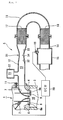
- An exhaust device 5 includes a first exhaust pipe 12, a second exhaust pipe 13, a third exhaust pipe 14, and an exhaust chamber 15, which are sequentially connected in this order from an upstream position toward a downstream position.
- the exhaust device 5 has the exhaust path 16 formed therein.
- the first exhaust pipe 12 is attached to the cylinder head 4 via an attaching bolt 11.
- the second exhaust pipe 13 is connected to a downstream end of the first exhaust pipe 12.
- the third exhaust pipe 14 is connected to a downstream end of the second exhaust pipe 13.
- the third exhaust pipe 14 and the exhaust chamber 15 are integrally formed.
- a first catalyst 17 and a second catalyst 18 are provided inside the exhaust device 5.
- the second catalyst 18 is located downstream with respect to the first catalyst 17.
- the first catalyst 17 and the second catalyst 18 have a space therebetween.
- a muffler (not shown) is connected to a downstream end of the exhaust chamber 15. Exhaust gas which flows into the inside of the exhaust chamber 15 passes the muffler and then is discharged outside.
- the exhaust chamber 15 is provided with an oxygen concentration sensor 19 for detecting an amount of oxygen in the exhaust gas.
- An ECU 20 which is a control device, controls the amount of fuel to be injected from the injector 2, the time to cause the ignition plug to ignite or the like, based on the rotational speed of the internal combustion engine 1, the opening angle of the throttle valve, the amount of oxygen in the exhaust gas detected by the oxygen concentration sensor 19 or the like.
- the ECU 20 controls the amount of fuel to be injected from the injector 2 such that, for example, the air/fuel ratio of the mixed gas to be absorbed into the internal combustion engine 1 is the theoretical air/fuel ratio.
- the exhaust device 5 includes a branch pipe 22.
- the branch pipe 22 has a branch section 21 formed therein. One end of the branch pipe 22 is connected to the exhaust path 16, and the other end of the branch pipe 22 is closed. The closed end of the branch pipe 22 acts as a reflecting section for reflecting a shock wave described later.
- the branch pipe 22 is integrally formed with the first exhaust pipe 12.
- the branch pipe 22 may be formed separately from, and fixed to, the first exhaust pipe 12.
- the first exhaust pipe 12 and the branch pipe 22 may be welded together or fixed to each other via a tightening member (not shown) such as a bolt or the like.
- the branch section 21 is formed to have a larger flow path cross-sectional area at the closed end than at the end thereof connected to the exhaust path 16, but the shape of the branch section 21 is not limited to that shown in FIG. 1 .
- the branch section 21 may have a chamber shape as shown in FIG. 1 , may have a pipe shape having a constant flow path cross-sectional area and having a closed tip, or may have a shape having a smaller flow path cross-sectional area at the closed end than at the end connected to the exhaust path.
- An entrance of the branch section 21 i.e., the portion connected to the exhaust path 16
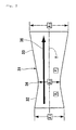
- a convergent-divergent nozzle (generally called “de Laval nozzle") 31 is provided downstream with respect to the branch section 21, a convergent-divergent nozzle (generally called “de Laval nozzle") 31 is provided downstream with respect to the branch section 21, a convergent-divergent nozzle (generally called “de Laval nozzle") 31 is provided downstream with respect to the branch section 21, a convergent-divergent nozzle 31 is provided downstream with respect to the branch section 21, a divergent section 33 provided downstream with respect to the convergent section 32 and having a flow path cross-sectional area which increases as the fluid progresses, and a throat section 34 provided between the convergent section 32 and the divergent section 33 and having the smallest flow path cross-sectional area.
- the arrow indicates the direction in which the fluid progresses.
- the convergent-divergent nozzle 31 accelerates the velocity of the exhaust gas flowing in the exhaust path 16 from a subsonic velocity to an ultrasonic velocity.
- flow path cross-sectional area A1 at an upstream end of the convergent section 32, flow path cross-sectional area A2 of the throat section 34, and flow path cross-sectional area A3 at a downstream end of the divergent section 33 have the relationships of A1 > A2 and A2 ⁇ A3.
- the flow path cross-sectional areas of the convergent section 32 and the divergent section 33 each change at a constant rate in the flow direction.
- the convergent section 32 and the divergent section 33 may be formed to have a shape having a flow path cross-sectional area changing step by step like a nozzle adopted for rockets, or may be formed to have a smoothly curved shape.
- the divergent section 33 is connected to the only one combustion chamber 10 provided upstream with respect to the divergent section 33 via the exhaust path 16. Therefore, the exhaust gas 36 discharged from the exhaust port 9a formed in the only one combustion chamber 10 flows into the divergent section 33.
- the convergent-divergent nozzle 31 is formed to fulfill the conditions represented by expressions (1) and (2) below.
- the exhaust gas in the divergent section 33 can be accelerated to an ultrasonic velocity.
- expression (1) represents the relationship between the shape of the exhaust pipe and the Mach number in a primary flow accompanied by viscous friction.
- Expression (2) represents ⁇ in expression (1).
- M represents the Mach number
- A represents the cross-sectional area of the exhaust pipe at an arbitrary cross-section
- D represents the diameter of the pipe at the arbitrary cross-section
- y represents the diameter of the pipe at the arbitrary cross-section
- x represents the distance in the flow direction
- f represents the frictional coefficient.
- the velocity of the fluid is the sonic velocity in the throat section and is an ultrasonic velocity in the divergent section 33.
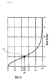
- FIG. 3 shows the pressure ratio of the full pressure P0 of the fluid in the convergent section 32 and the static pressure P of the fluid in the divergent section 33, i.e., P/P0, and the velocity of the fluid passing the divergent section 33 at each pressure ratio.
- FIGS. 4 (A) through 4 (C) schematically show the exhaust device 5.
- identical or equivalent elements to those in FIG. 1 or FIG. 2 bear identical reference numerals assigned thereto.
- the velocity of the exhaust gas 36 also decreases as the exhaust gas 36 progresses in the exhaust path 16. As shown in FIG. 4(A) , the shock wave 35 propagates in the downstream direction in the exhaust path 16. Meanwhile, the exhaust gas 36 progresses in the downstream direction in the exhaust path 16 with a delay with respect to, and at a lower velocity than, the shock wave 35.
- the shock wave 35 progressing in the exhaust path 16 is separated into a shock wave propagating in the exhaust path 16 and a shock wave propagating in the branch section 21 at an entrance 21a of the branch section 21, and then these shock waves progress separately in the exhaust path 16 and the branch section 21.
- the shock wave 35 propagating in the exhaust path 16 is attenuated and disappears after passing the convergent-divergent nozzle 31.
- the branched shock wave 35 propagating in the branch section 21 is reflected by the reflecting section 21b of the branch section 21 and propagates oppositely in the branch section 21 to return to the exhaust path 16.
- the time from when the exhaust port 9a is opened and the exhaust gas 36 is generated until the exhaust gas 36 reaches the entrance 21a of the branch section 21 is set as T 1 .
- the time from when the shock wave 35 is generated at the exhaust port 9a until the shock wave 35 is reflected by the reflecting section 9b of the branch section 21b and reaches the entrance 21a of the branch section 21 is set as T 2 .
- T 1 ⁇ T 2 is fulfilled, as shown in FIG. 4(C) , the shock wave 35 and the exhaust gas 36 collide against each other at a position downstream with respect to the entrance 21a of the branch section 21.
- the branch section 21 has such a length that the shock wave 35 reflected by the branch section 21 and the exhaust gas 36 collide against each other at the entrance 21a of the branch section 21.
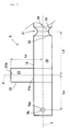
- the distance from center 9ac of the exhaust port 9a to center line X of the flow path cross-section at the entrance 21a of the branch section 21 is set as Le
- the distance from center line Y of the flow path cross-section of the exhaust path 16 to the reflecting section 21b is set as Ls.
- the velocity of the exhaust gas 36 is set as Ve
- the propagation velocity of the shock wave 35 is set as Vs.
- time T 1 which is from when the exhaust port 9a is opened until the exhaust gas 36 reaches the entrance 21a of the branch section 21, is represented by expression (3) .
- Time T 2 which is from when the exhaust port 9a is opened until the shock wave is reflected by the reflecting section 21b of the branch section 21 and reaches the center line Y of the exhaust path 16, is represented by expression (4).
- T 1 is equal to or smaller than T 2 (T 1 ⁇ T 2 )
- the reflected shock wave 35 and the exhaust gas 36 collide against each other at a position downstream with respect to the entrance 21a of the branch section 21.
- Le/Ve ⁇ (Le + 2Ls)/Vs the shock wave 35 and the exhaust gas 36 collide against each other at a position downstream with respect to the entrance 21a of the branch section 21.
- the maximum velocity of the exhaust gas 36 may be regarded as the velocity Ve, or the average velocity of the exhaust gas 36 may be regarded as the velocity Ve.
- the maximum propagation velocity of the shock wave 35 may be regarded as the propagation velocity Vs, or the average propagation velocity of the shock wave 35 may be regarded as the propagation velocity Vs.
- the distance from the center line X of the flow path cross-section at the entrance 21a of the branch section 21 to an upstream end of the divergent section 33 of the convergent-divergent nozzle 31 is set as Ld, and the time from when the exhaust valve 9 is opened until the exhaust valve 9 is closed is set as tv.
- Time T 3 which is from when the exhaust port 9a is opened until a trailing end of the exhaust gas 36 reaches the upstream end of the divergent section 33, is represented by expression (5).
- Time T 4 which is from when the exhaust port 9a is opened until the shock wave is reflected by the reflecting section 21b and reaches the upstream end of the divergent section 33, is represented by expression (6).
- T 3 tv + Le + Ld / Ve
- T 4 Le + 2 ⁇ Ls + Ld / Vs
- T 4 Le + 2 ⁇ Ls + Ld / Vs
- the distance Ls between the entrance 21a of the branch section 21 and the reflecting section 21b is relatively short, the attenuation of the shock wave 35 in the branch section 21 is suppressed.
- the distance Ls may be shorter than the distance Le.
- the pressure of the exhaust 36 flowing in the exhaust path can be increased.
- the full pressure P0 upstream with respect to an entrance of the convergent-divergent nozzle 31 is increased.
- the ratio of the full pressure P0 upstream with respect to the entrance and the static pressure P downstream with respect to the throat section 34 i.e., P/P0, becomes lower than the critical pressure ratio of 0.528.
- the velocity of the exhaust gas 36 reaches the sonic velocity in the throat section 34.
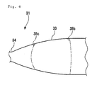
- FIG. 6 is a schematic view drawn based on a photograph of an inside of the convergent-divergent nozzle taken by the Schlieren method.
- a new shock wave is generated in the convergent-divergent nozzle 31.
- the new shock wave 35b is accelerated when passing the divergent section 33 of the convergent-divergent nozzle 31.
- an expansion wave 35c progressing oppositely to the shock wave 35b is generated.
- the pressure of the exhaust gas 36 present between the shock wave 35b and the expansion wave 35c is significantly decreased to be equal to or lower than the atmospheric pressure by an adiabatic cooling effect caused by adiabatic expansion.
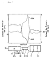
- FIG. 7 and FIG. 8 show the results of simulations performed by the present inventors.
- FIG. 7 shows the exhaust gas velocity and the exhaust gas pressure at points in the exhaust path 16 immediately after the new shock wave 35b is generated in the convergent-divergent nozzle 31.
- FIG. 8 shows the exhaust gas velocity and the exhaust gas temperature at the points in the exhaust path 16 immediately after the new shock wave 35b is generated in the convergent-divergent nozzle 31.
- the shock wave 35b is accelerated in the divergent section 33.
- the throat section 34 of the convergent-divergent nozzle 31 is set to be relatively long. After the shock wave 35 reflected by the branch section 21 collides against the exhaust gas 36, the shock wave 35 propagates in the throat section 34 preceding the exhaust gas 36. At this point, adiabatic expansion is generated in the space between the exhaust gas 36 and the shock wave 35a and thus the pressure is decreased. Therefore, the exhaust gas 36 is sucked by the shock wave 35 to flow in the throat section 34, without decreasing in velocity thereof.
- the timing at which the shock wave 35b is to be accelerated in the divergent section 33 in other words, the timing at which the pressure and temperature of the exhaust gas are to be decreased, can be set in accordance with the internal combustion engine.
- the internal combustion engine 1 according to this embodiment can significantly decrease the temperature and pressure of the exhaust gas in the exhaust path 16 as compared to the conventional art.
- the internal combustion engine 1 according to this embodiment has only one combustion chamber 10 upstream with respect to the divergent section 33, and so is not influenced by exhaust gas from the other cylinders unlike in the conventional art. By decreasing the temperature and pressure of the exhaust gas in this manner, the performances of the internal combustion engine 1 can be improved, for example, as described below.
- the temperature of the exhaust gas 36 in the exhaust path 16 can be decreased upstream with respect to the first catalyst 17. Therefore, the temperature of the first catalyst 17 and the second catalyst 18 is prevented from increasing excessively.
- the phenomenon called "sintering" occurs to lower the cleaning efficiency.
- sintering can be effectively prevented. Since sintering is prevented in this embodiment even when the internal combustion engine is driven in a high load state, the fuel can be combusted at the theoretical air/fuel ratio. Therefore, the exhaust gas 36 can be efficiently cleaned by the first catalyst 17 and the second catalyst 18.
- the cleaning performance which is one performance of the internal combustion engine 1
- two catalysts are located in series in the middle of the exhaust path 16, but the present invention is not limited to this. There may be only one catalyst, or three or more catalysts. A plurality of catalysts may be located in parallel.
- the pumping loss of the internal combustion engine 1 can be reduced.
- the pressure of the exhaust gas in the exhaust path 16 is significantly decreased.
- the piston (not shown) of the internal combustion engine 1 is pulled toward the exhaust path 16, namely, toward the top dead center, in the exhaust stroke, and so the work necessary for driving the piston in the exhaust stroke is reduced.
- FIG. 9(A) shows a P-V diagram of a conventional internal combustion engine
- FIG. 9 (B) shows a P-V diagram of the internal combustion engine 1 in this embodiment.
- a region surrounded by the closed curve appears in the vicinity of the top dead center of the exhaust stroke of the internal combustion engine (in the region surrounded by the one-dot chain line).
- the region surrounded by the closed curve corresponds to the work conducted by the internal combustion engine 1. Namely, when the pressure of the exhaust gas is significantly decreased by the generation of the shock wave 35b in the divergent section 33, the piston is pulled by the exhaust gas, which enables the internal combustion engine 1 to perform positive work in the exhaust stroke.
- Embodiment 2 since the pressure of the exhaust gas in the exhaust path 16 is decreased, secondary air is easily supplied to the exhaust path 16. Thus, as shown in FIG. 10 , an air path 71 for supplying secondary air can be provided in the exhaust path 16. Except for this structural difference, Embodiment 2 is exactly the same as Embodiment 1. Accordingly, the detailed description of Embodiment 2 is provided by the detailed description of FIG. 1 through FIG. 9 regarding Embodiment 1.
- An air supply pipe 72 is connected between the branch pipe 22 and the convergent-divergent nozzle 31 in the first exhaust pipe 12. A leading end of the air supply pipe 72 extends to the inside of the exhaust path 16. An air outlet 73 is formed to be slit-like at the leading end of the air supply pipe 72. Owing to this structure, the air supply pipe 72 can supply air to a wide region of the exhaust path 16.
- An upstream end of the air supply pipe 72 is connected outside the internal combustion engine via a lead valve 74 and an air amount control value 75.
- the lead valve 74 prevents the exhaust gas from flowing outside the internal combustion engine from the air supply pipe 72.
- the lead valve 74 is structured to be opened by a negative pressure generated in the exhaust path 16 to cause the air to flow toward the air outlet 73 of the air supply pipe 72.
- the air amount control valve 75 is provided for adapting the amount of the air to the driving state of the internal combustion engine 1.
- the air amount control valve 75 includes an actuator, a servo motor, a solenoid or the like. The opening angle of the air amount control valve 75 is controlled by the ECU 20.
- the air supply pipe 72 may be connected to the intake path of the internal combustion engine 1.
- the ECU 20 When the opening angle of the throttle valve is smaller than a prescribed angle, the ECU 20 causes the air amount control valve 75 to close or to relatively decrease the opening angle of the throttle valve.
- the prescribed angle is preset and stored in the ECU 20.
- the ECU 20 increases the opening angle of the air amount control valve 75. As seen from this, the opening angle of the air amount control valve 75 is increased or decreased in accordance with the opening angle of the throttle valve.
- the provision of the air amount control valve 75 allows the air to be supplied to the exhaust path 16 at an appropriate flow rate with no excessiveness or shortage.
- the air amount control valve 75 is not absolutely necessary and may be omitted.
- the air can be efficiently supplied into the exhaust path 16 by a negative pressure generated in the exhaust path 16.
- the negative pressure is significantly higher than, namely, the pressure is significantly lower than, that in a general internal combustion engine which does not include the convergent-divergent nozzle 31 or the branch pipe 22.
- the phenomenon that a negative pressure is generated by the action of the convergent-divergent nozzle 31 continues even when the rotational speed of the internal combustion engine 1 increases to be higher than the rotational speed at the time of the maximum output. Therefore, in this embodiment, even when the rotational speed of the internal combustion engine 1 becomes high, a sufficient amount of air can be supplied to the exhaust path 16.
- the temperature of the air to be supplied to the exhaust path 16 is roughly equal to the temperature of the outside air, and is significantly lower than that of the exhaust gas. Therefore, in this embodiment, the temperature of the exhaust gas can be further decreased by the air having a low temperature, which is supplied into the exhaust path 16 in a large amount. Also in this embodiment, a large amount of air can be supplied upstream with respect to the first catalyst 17. Therefore, even where the amount of fuel to be injected is increased in order to make the air/fuel ratio of the internal combustion engine 1 smaller than the theoretical air/fuel ratio, exhaust gas containing an equivalent amount of oxygen to where the air/fuel ratio is the theoretical air/fuel ratio can be supplied to the first catalyst 17.
- the temperature of the exhaust gas can also be decreased by making the air/fuel ratio of the internal combustion engine 1 smaller than the theoretical air/fuel ratio and thus decreasing the combustion temperature.
- the air/fuel ratio is smaller than the theoretical air/fuel ratio, it is possible to cool the elements in the vicinity of the combustion chamber 10 (intake valve 8, exhaust valve 9, valve seat, piston, etc.) with the extra fuel.
- the reliability of theinternalcombustion engine 1 can be improved.
- the branch pipe 22 is used as a part of a secondary air supply pipe.
- the lead valve 74 connected to the air supply pipe 72 is attached to the branch pipe 22.
- Embodiment 3 is exactly the same as Embodiment 1. Accordingly, the detailed description of Embodiment 3 is provided by the detailed description of FIG. 1 through FIG. 9 regarding Embodiment 1.
- the lead valve 74 acts as the reflecting section 21b of the branch pipe 22.
- an air supply path 71 is communicated to the exhaust path 16 via the branch section 21.
- the air supply pipe 72 may be inserted between a connection portion of the exhaust path 16 and the branch pipe 22 and a tip portion of the branch pipe 22.
- the lead valve 74 when the exhaust valve 9 is opened, the lead valve 74 is closed. Thus, the shock wave can be reflected by the lead valve 74.
- the lead valve 74 When a negative pressure is generated in the exhaust path 16 by the action of the convergent-divergent nozzle 31, the lead valve 74 is opened and air can be supplied into the exhaust path 16 via the branch section 21. In this embodiment also, a sufficient amount of air can be supplied into the exhaust path 16.
- the exhaust device 5 in this embodiment costs less than the exhaust device 5 using the exclusive branch section 21 (e.g., the exhaust device 5 in Embodiment 2).
- Embodiment 4 As shown in FIG. 12 , in Embodiment 4, the branch pipe 22 is used as a part of the convergent-divergent nozzle. Except for this structural difference, Embodiment 4 is exactly the same as Embodiment 1. Accordingly, the detailed description of Embodiment 4 is provided by the detailed description of FIG. 1 through FIG. 9 regarding Embodiment 1.
- the convergent section 32, the throat section 34 and the divergent section 33 are formed in a portion of the exhaust path 16 which is downstream with respect to the branch section 21.
- the present inventors conceived of a structure providing the same effect with a simpler structure.
- a branch section 21 for reflecting and propagating the shock wave 35 back to the exhaust path 16 is provided.
- the exhaust path 16 has the flow path cross-sectional area thereof increased at the position of the branch section 21 and decreased downstream with respect to that position.
- the convergent section 32 and the throat section 34 are formed in the exhaust path by the branch section 21.
- flow path cross-sectional area A5 of a portion of the exhaust path 16 which is upstream with respect to the entrance 21a of the branch section 21 is roughly the same as flow path cross-sectional area A7 of a portion of the exhaust path 16 which is downstream with respect to the entrance 21a of the branch section 21, there is the following relationship.
- a sum of flow path cross-sectional area A5 of the portion of the exhaust path 16 which is upstream with respect to the entrance 21a of the branch section 21 and flow path cross-sectional area A4 of the branch section 21 is larger than flow path cross-sectional area A7 of the portion of the exhaust path 16 which is downstream with respect to the entrance 21a.
- the convergent section 32 and the throat section 34 are formed downstream with respect to the entrance 21a. Therefore, merely by providing the divergent section 33 downstream with respect to the entrance 21a, the convergent-divergent nozzle 31 can be substantially formed.
- A6 represents the flow path cross-sectional area of the divergent section 33, and A7 ⁇ A6.
- a portion between the entrance 21a and the divergent section 33 is the throat section 34.
- the throat section 34 may be lengthy along the flow direction as shown here.
- the flow path cross-sectional area of the convergent section 32 and the divergent section 33 is not limited to be smoothly changing in the downstream direction, and may change step by step.
- the internal combustion engine 1 puts the exhaust gas into a low pressure and low temperature state by the following method.
- the fuel is combusted in the combustion chamber 10.
- the exhaust valve 9 for opening or closing the exhaust port 9a of the combustion chamber 10 is opened to discharge the exhaust gas 36 to the exhaust path 16 from the combustion chamber 10.
- the shock wave 35 propagating in the exhaust path 16 at a higher velocity than the exhaust gas 36 is generated. At least a part of the shock wave 35 is branched from the exhaust path 16, and the branched shock wave 35 is propagated back to the exhaust path 16 to cause the shock wave 35 to collide against the exhaust gas, thereby increasing the pressure of the exhaust gas.
- the flow path cross-sectional area of the exhaust path 16 is decreased to increase the pressure of the exhaust gas 36.
- the pressure of the exhaust gas is increased by causing the exhaust gas to flow in a portion of the exhaust path 16 in which the flow path cross-sectional area is decreased in the downstream direction.
- the velocity of the exhaust gas 36 is increased by increasing the flow path cross-sectional area of the exhaust path 16.
- the velocity of the exhaust gas is increased by causing the exhaust gas to flow in a portion of the exhaust path 16 in which the flow path cross-sectional area is increased in the downstream direction.
- the new shock wave 35b propagating in the downstream direction in the exhaust path 16 is generated to form a region of a negative pressure in the exhaust path 16.
- the exhaust gas is put into a low pressure and low temperature state by an adiabatic cooling effect caused by adiabatic expansion. Therefore, the exhaust gas can be put into the low pressure and low temperature state even where the internal combustion engine 1 is driven in a high load state or at a high velocity.
- FIG. 13 shows the relationship between the exhaust gas velocity and the exhaust gas pressure in the exhaust path 16 in time sequence.
- FIG. 14 shows the relationship between the exhaust gas pressure and the exhaust gas temperature in the exhaust path 16 in time sequence.
- the waveforms shown in FIG. 7 represent the relationship between the exhaust gas velocity and the exhaust gas pressure when the shock wave is being accelerated as shown in FIG. 13(C).
- FIG. 13 (A) and FIG. 14 (A) show the respective relationship immediately after the exhaust port is opened.
- FIG. 13(B) and FIG. 14(B) show the respective relationship immediately after the exhaust gas and the shock wave collide against each other downstream with respect to the branch section 21.
- FIG. 13(C) and FIG. 14(C) show the respective relationship when the shock wave is being accelerated in the divergent section 33.
- FIG. 13(D) and FIG. 14(D) show the respective relationship after the shock wave is accelerated.
- the exhausting method for the internal combustion engine in this embodiment is as follows.
- FIG. 13 (A) shows the exhaust gas velocity and the exhaust gas pressure immediately after the exhaust port 9a is opened. As shown in FIG. 13 (A) , when the exhaust port 9a is opened, the pressure of the exhaust gas in the vicinity of the exhaust port 9a becomes higher than the atmospheric pressure.
- FIG. 14(A) shows the exhaust gas pressure and the exhaust gas temperature immediately after the exhaust port 9a is opened. As shown in FIG. 14 (A) , the temperature of the exhaust gas becomes very high by receiving the combustion heat.
- the branch section 21 branches at least a part of the shock wave propagating in the exhaust path 16, from the exhaust path 16.
- the reflecting section 21b of the branch section 21 reflects the branched shock wave.
- the reflected shock wave propagates in the branch section 21 and again in the exhaust path 16.
- the reflected shock wave collides against the exhaust gas flowing in the exhaust path 16, which increases the pressure of the exhaust gas.
- the flow path cross-sectional area of the exhaust path 16 is decreased in the convergent section 32, which increases the pressure of the exhaust gas. Either the increase of the exhaust gas pressure caused by the collision of the shock wave and the exhaust gas, or the increase of the exhaust gas pressure caused by the decrease of the flow path cross-sectional area, may occur first.
- FIG. 13(B) shows the exhaust gas velocity and the exhaust gas pressure immediately after the exhaust gas pressure is increased.
- the exhaust gas pressure is higher than that at the time of FIG. 13(A) .
- the exhaust gas velocity is higher than that at the time of FIG. 13 (A) .
- FIG. 14 (B) shows the exhaust gas pressure and the exhaust gas temperature immediately after the exhaust gas pressure is increased. As shown in FIG. 14(B) , the exhaust gas temperature is lower in the vicinity of the exhaust port 9a, but is higher upstream with respect to the convergent section 32, than that at the time of FIG. 14(A) .
- the flow path cross-sectional area of the exhaust path 16 is increased in the divergent section 33 to decrease the exhaust gas pressure.
- the exhaust gas pressure is decreased to be equal to or lower than the critical pressure ratio, a new shock wave propagating in the downstream direction in the exhaust path 16 is generated.
- an expansion wave progressing in the upstream direction is generated at the same time.
- the new shock wave is accelerated in the divergent section 33. Therefore, the fluid present in the space between the shock wave progressing in the downstream direction in the exhaust path 16 and the expansion wave progressing in the upstream direction in the exhaust path 16 expand rapidly. This can decrease the pressure of the exhaust gas flowing in the exhaust path 16.
- a region of a negative pressure can be generated in the exhaust path 16.
- FIG. 13(C) shows the exhaust gas velocity and the exhaust gas pressure when the shock wave is being accelerated in the divergent section.
- the exhaust gas pressure is rapidly decreased from that at the time of FIG. 13 (B) upstream with respect to the divergent section 33, to become a negative pressure.
- the exhaust gas velocity upstream with respect to the divergent section 33 is rapidly increased.
- FIG. 14 (C) shows the exhaust gas pressure and the exhaust gas temperature when the shock wave is being accelerated in the divergent section 33.
- the exhaust gas temperature is rapidly decreased from that at the time of FIG. 14(B) .
- FIG. 13 (D) shows the exhaust gas velocity and the exhaust gas pressure after the shock wave is accelerated.
- the influence of the exhaust gas pressure which is decreased upstream with respect to the divergent section 33 at the time of FIG. 13 (C) , is exerted even on the exhaust port 9a up stream with respect to the convergent section 32. Therefore, the exhaust gas pressure becomes a negative pressure also in the vicinity of the exhaust port 9a.
- FIG. 14(D) shows the exhaust gas pressure and the exhaust gas temperature after the shock wave is accelerated.
- the exhaust gas temperature can also be significantly decreased in the vicinity of the exhaust port. This can also cool the exhaust valve 9 and suppress the deterioration thereof.
- the exhaust gas temperature downstream with respect to the divergent section 33 does not change much.
- the exhaust gas of a high temperature in the vicinity of the exhaust port 9a shown in FIG. 14 (A) is cooled by an adiabatic cooling effect in the divergent section 33, the exhaust gas temperature downstream with respect to the divergent section 33 can be prevented from being changed.
- the first catalyst 17 and the second catalyst 18 are provided downstream with respect to the divergent section 33. Since the exhaust gas temperature downstream with respect to the divergent section 33 can be prevented from being changed as described above, the temperature of the exhaust gas passing the first catalyst 17 and the second catalyst can be prevented from becoming excessively high. This can prevent sintering of the catalysts even where the internal combustion engine 1 is driven at a high load or in a high rotational speed range.
- the secondary air can be supplied to the exhaust path.
- a negative pressure region is generated upstream with respect to the divergent section 33. Therefore, by connecting the secondary air supply path upstream with respect to the divergent section 33, secondary air can be supplied to the exhaust path 16.
- the internal combustion engine according to the present invention is applied for, for example, a vehicle such as a motorcycle or an outboard motor mounted on a marine vessel.
- the present invention is applicable for any of various types of internal combustion engines.
- FIG. 15 shows a marine vessel having an internal combustion engine according to the present invention mounted thereon.
- FIG. 15 shows a marine vessel 100 having two outboard motors 101 each having an internal combustion engine 1 according to the present invention mounted thereon.
- the outboard motors 101 are attached to a stern 103 of the marine vessel 100 and can drive the marine vessel forward.
- An exhaust path of each outboard motor 101 is provided below the water surface, and the exhaust gas is discharged from the exhaust path into the water.
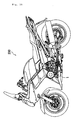
- FIG. 16 shows a vehicle having an internal combustion engine according to the present invention mounted thereon.
- FIG. 16 shows a motorcycle 200 having an internal combustion engine 1 located at the center of the body thereof. There is no limitation on the application target of the internal combustion engine according to the present invention.
- the internal combustion engine 1 in each of the above embodiments includes one exhaust device 5 for one combustion chamber 10.
- a plurality of exhaust devices 5 may be provided for one combustion chamber 10.
- the internal combustion engine according to the present invention may be a multi-cylinder engine as long as the divergent section is connected to only one combustion chamber upstream with respect to the divergent section.
- each cylinder may have a separate exhaust path, and the branch section for reflecting the shock wave and the divergent section may be provided in each cylinder.
- each cylinder has a separate exhaust path, and the branch section for reflecting the shock wave and the divergent section are provided in each cylinder similarly. Owing to such a structure, even in a multi-cylinder engine, the exhaust gas pressure can be decreased upstream with respect to the divergent section of each exhaust path without being influenced by the exhaust gas from the other cylinders.
- Embodiment 1 by accelerating the shock wave in the convergent-divergent nozzle, a negative pressure is generated upstream with respect to the shock wave, and the pressure of the exhaust gas, and thus the temperature of the exhaust gas, can be decreased by an adiabatic cooling effect caused by adiabatic expansion.
- the convergent section and the divergent section have therebetween a portion having a constant flow path cross-sectional area.
- the timing at which the shock wave is to be accelerated in the divergent section in other words, the timing at which the exhaust gas pressure and temperature are to be decreased, can be set in accordance with the internal combustion engine.
- an air path for supplying secondary air to the exhaust path is provided. Therefore, the secondary air can be efficiently supplied to the exhaust path using the negative pressure generated upstream with respect to the shock wave. This can efficiently decrease the exhaust gas temperature.
- the temperature of the exhaust gas passing the catalyst can be decreased. This can, for example, prevent the sintering of the catalyst.
- Embodiment 3 air is supplied to the branch section 21. Therefore, a path acting exclusively as the branch section 21 is not formed. For this reason, as compared to Embodiment 1 and Embodiment 2 in which the dedicated branch section 21 is used, the costs are reduced and the degree of freedom of layout can be improved.
- a new shock wave can be generated by a simpler structure.
Landscapes
- Engineering & Computer Science (AREA)
- Chemical & Material Sciences (AREA)
- Combustion & Propulsion (AREA)
- Mechanical Engineering (AREA)
- General Engineering & Computer Science (AREA)
- Chemical Kinetics & Catalysis (AREA)
- Health & Medical Sciences (AREA)
- Toxicology (AREA)
- Exhaust Silencers (AREA)
- Characterised By The Charging Evacuation (AREA)
- Exhaust Gas After Treatment (AREA)
Abstract
Description
- The present invention relates to an internal combustion engine, a vehicle, a marine vessel, and an exhausting method for an internal combustion engine.
- Conventionally, in order to enhance the performances of internal combustion engines, gas exhaust devices of the internal combustion engines have been improved. For example, as described in
patent document 1, an internal combustion engine including a convergent-divergent nozzle (generally called "de Laval nozzle") has been proposed in order to enhance the scavenging efficiency. The nozzle includes a convergent section having a flow path cross-sectional area which is decreased as a fluid progresses, a divergent section provided downstream with respect to the convergent section and having a flow path cross-sectional area which increases as the fluid progresses, and a throat section provided between the convergent section and the divergent section. When the pressure ratio of the pressure P0 in the convergent section and the pressure P in the divergent section (i.e., P/P0) is smaller than the critical pressure ratio (for the air, about 0.528), the velocity of the fluid exceeds the sonic velocity in the divergent section.Patent document 1 has an object of improving the scavenging efficiency using this function of this nozzle. Specifically, as shown inFigure 1 ofpatent document 1, six exhaust ports of the inline six-cylinder internal combustion engine are merged together into an exhaust merging pipe. In addition, the exhaust path thereof is set to have a length that increases the scavenging efficiency, and the nozzle is provided at the exhaust outlet of the exhaust merging pipe.Patent document 1 describes that the exhaust gas flow, which has passed the nozzle and thus is increased in velocity, absorbs the exhaust gas remaining in the exhaust merging pipe, and thus the scavenging efficiency can be improved. - Patent document 1: Japanese Laid-Open Utility Model Publication No.
1-76520 - The present inventors have studied internal combustion engines using the function of a convergent-divergent nozzle as described in
patent document 1. While studying the internal combustion engines,the present inventors discovered that when the velocity of exhaust gas is increased to the sonic velocity to generate a shock wave, the pressure in a region upstream with respect to the shock wave is decreased. The present inventors conceived of enhancing the performances of an internal combustion engine by generating a negative pressure in the exhaust path using such a decrease of the pressure in the region upstream with respect to the shock wave. However, as a result of actively studyingpatent document 1, the present inventors discovered that even if the velocity of the exhaust gas becomes high due to the action of the convergent-divergent nozzle, a negative pressure cannot be generated in a portion of the exhaust merging pipe which is upstream with respect to the nozzle for the following reasons. The internal combustion engine described inpatent document 1 is a six-cylinder internal combustion engine and explodes every 120 degree crank angle. Therefore, a pressure wave is generated in the exhaust path at an interval of 120 degrees. In general, the angle at which the exhaust port of an internal combustion engine is opened (work angle) is about 240 degrees. In the internal combustion engine described inpatent document 1, the ports of the cylinders are merged into one convergent-divergent nozzle at a position upstream with respect thereto. Therefore, while the exhaust port of one cylinder is opened, the exhaust port of at least one of the remaining cylinders is opened. Before the exhaust port of one cylinder is closed, the exhaust port of the cylinder in which the next explosion is to occur is opened and the next pressure wave is generated. For this reason, the inside of the exhaust merging pipe is always in a positive pressure state. Even if the pressure ratio of the pressure P0 in the convergent section and the pressure P in the divergent section (i.e., P/P0) is decreased to be lower than the critical pressure ratio and the velocity of the exhaust gas exceeds the sonic velocity in the divergent section, the inside of the exhaust merging pipe always stays in the positive pressure state. As a result, the performances of the internal combustion engine cannot be expected to be fully improved. - The present invention made in light of such circumstances has an object of providing a novel internal combustion engine offering improved performances by applying the principle of the convergent-divergent nozzle.
- As one means for solving the above problem, it is conceived to connect the divergent section to the only one combustion chamber which is provided upstream with respect thereto. As a result of this arrangement, it is made impossible that while the exhaust port of one cylinder is opened, a pressure wave generated in the exhaust port of another cylinder propagates to the exhaust path connected to the exhaust port which has been opened. Therefore, a positive pressure and a negative pressure are alternately generated in a portion of the exhaust path which is upstream with respect to the divergent section. However, it was discovered that with this structure, a large negative pressure cannot be generated in the exhaust path for the following reasons and due to the following problems. One problem is that a shock wave generated when the exhaust port in the combustion chamber is opened is attenuated before reaching an upstream end of the divergent section. Another problem is that the pressure of the exhaust gas flowing in the exhaust path with a delay with respect to the shock wave is attenuated before the exhaust gas reaches the upstream end of the divergent section. For these reasons, even if either the shock wave or the exhaust gas reaches the upstream end of the divergent section, the pressure ratio of the pressure P0 in the convergent section and the pressure P in the divergent section does not become smaller than the critical pressure ratio. Therefore, the velocity of the fluid passing the exhaust path does not exceed the sonic velocity, and thus the function of the convergent-divergent nozzle cannot be obtained.
- An internal combustion engine according to the present invention comprises a combustion chamber having an exhaust port; an exhaust valve for opening or closing the exhaust port; and an exhaust device having an exhaust path for guiding exhaust gas discharged from the combustion chamber via the exhaust port. The exhaust device comprises a convergent section having a flow path cross-sectional area smaller at a downstream end thereof than at an upstream end thereof; a divergent section provided downstream with respect to the convergent section and having a flow path cross-sectional area larger at a downstream end thereof than at an upstream end thereof; and a branch section for branching a shock wave, propagating in a downstream direction in the exhaust path at a higher velocity than the exhaust gas flowing into the exhaust path from the combustion chamber when the exhaust valve is opened, from a portion of the exhaust path which is upstream with respect to the divergent section, and propagating the branched shock wave back to the exhaust path. The divergent section is connected to the only one combustion chamber provided upstream with respect to the divergent section. The exhaust gas flowing into the exhaust path from the combustion chamber is caused to pass the convergent section and to collide against the shock wave which has propagated in the branch section, between the branch section and the divergent section, thus to increase the pressure of the exhaust gas in the convergent section. The exhaust gas is caused to pass the divergent section to generate a new shock wave, and a negative pressure is generated upstream with respect to the divergent section in the exhaust path by the generated new shock wave.
- According to the present invention, the divergent section is connected to only one combustion chamber provided upstream with respect thereto, and also the branch section is provided in a portion of the exhaust path which is upstream with respect to the divergent section. As a result, the shock wave propagating in the exhaust pipe at a higher velocity than the exhaust gas flowing from the combustion chamber into the exhaust path when the exhaust port is opened is branched from the portion of the exhaust path which is upstream with respect to the divergent section, is propagated back to the exhaust path after being delayed in the branch section, and is caused to collide against the exhaust gas flowing with a delay. Therefore, the pressure of the exhaust gas is increased. In addition, since the exhaust gas is caused to pass the divergent section, the pressure of the exhaust gas is increased. Since the exhaust gas is caused to pass the divergent section, a new shock wave propagating in a downstream direction is generated. Since a positive pressure and a negative pressure are alternately generated in the portion of the exhaust path which is upstream with respect to the divergent section and also the pressure upstream with respect to the new shock wave is decreased, a large negative pressure is generated in the portion of the exhaust path which is upstream with respect to the divergent section. This can improve the performances of the internal combustion engine.
-
-
FIG. 1 shows a structure of an exhaust device of an internal combustion engine according toEmbodiment 1, and is a cross-sectional view of an exhaust path and the like thereof. -
FIG. 2 shows a structure of a convergent-divergent nozzle. -
FIG. 3 shows the relationship between the pressure ratio and the Mach number in the convergent-divergent nozzle. -
FIG. 4 provides cross-sectional views of the exhaust path and the like showing the progressing state of a shock wave and exhaust gas; (A) shows an initial state of an exhaust stroke, (B) shows a state where the shock wave propagates to a branch section, and (C) shows a state where the shock wave reflected by the branch section collides against the exhaust gas. -
FIG. 5 is a schematic view of the exhaust path and the like, showing a route in the exhaust path in which the shock wave progresses and a route in the exhaust path in which the exhaust gas progresses. -
FIG. 6 is a schematic view drawn based on a photograph of an inside of the convergent-divergent nozzle taken by the Schlieren method. -
FIG. 7 is a graph showing the relationship between the exhaust gas velocity and the exhaust gas pressure when the shock wave is accelerated. -
FIG. 8 is a graph showing the relationship between the exhaust gas velocity and the exhaust gas temperature when the shock wave is accelerated. -
FIG. 9 provides P-V diagrams representing the pumping loss; (A) shows a P-V diagram of a conventional internal combustion engine, and (B) shows a P-V diagram of an internal combustion engine according to the present invention. -
FIG. 10 shows a structure of an internal combustion engine according toEmbodiment 2, and is a cross-sectional view of an exhaust path and the like thereof. -
FIG. 11 shows a structure of an internal combustion engine according toEmbodiment 3, and is a cross-sectional view of an exhaust path and the like thereof. -
FIG. 12 shows a structure of an internal combustion engine according toEmbodiment 4, and is a cross-sectional view of an exhaust path and the like thereof. -
FIG. 13 shows the relationship between the exhaust gas velocity and the exhaust gas pressure in time sequence. -
FIG. 14 shows the relationship between the exhaust gas pressure and the exhaust gas temperature in time sequence. -
FIG. 15 shows an example of a marine vessel including an outboard motor having an internal combustion engine mounted thereon. -
FIG. 16 shows an example of a motorcycle having an internal combustion engine mounted thereon. - As a result of active studies, the present inventors conceived of an idea that a large negative pressure can be generated in the exhaust path by applying the principle of the convergent-divergent nozzle and using the following method not conventionally known. The present inventors found that this can improve the performances of an internal combustion engine.
- The method is as follows. (1) A shock wave preceding the exhaust gas is branched; (2) The branched shock wave is delayed such that the shock wave collides against the exhaust gas, thereby increasing the pressure of the exhaust gas; (3) The exhaust gas having the increased pressure is caused to pass the divergent section to be accelerated to an ultrasonic velocity, thereby generating a shock wave; and (4) A negative pressure is generated in a portion of the exhaust path which is upstream with respect to the divergent section.
- Hereinafter, an internal combustion engine according to an embodiment of the present invention will be described in detail with reference to the drawings. In the following description, the terms "upstream" and "downstream" respectively refer to upstream and downstream with respect to the direction in which a fluid such as exhaust gas or the like flows.
- As shown in
FIG. 1 , aninternal combustion engine 1 includes acylinder body 3 and acylinder head 4. In thecylinder body 3 and thecylinder head 4, acombustion chamber 10 is formed. Theinternal combustion engine 1 is a four-cycle gasoline engine. Theinternal combustion engine 1 may be of an air-cooled type or of a water-cooled type. Thecylinder head 4 has adownstream section 6 of an intake path and anupstream section 7 of anexhaust path 16 formed therein. Thecylinder head 4 accommodates anintake valve 8 for opening or closing anintake port 8a, anexhaust valve 9 for opening or closing anexhaust port 9a, a valve driving mechanism (not shown) for driving theintake valve 8 and theexhaust valve 9, and the like. In this embodiment, onedownstream section 6 of the intake path and oneupstream section 7 of the exhaust path are provided for onecombustion chamber 10. Alternatively, a plurality ofintake ports 8a, a plurality ofexhaust ports 9a, a plurality ofintake valves 8, a plurality ofexhaust valves 9, a plurality ofdownstream sections 6 of the intake path and a plurality ofupstream sections 7 of the exhaust path may be provided for one combustion chamber. Aninjector 2 for injecting fuel is attached to thecylinder head 4. Although not shown, thecylinder 4 is also provided with an ignition plug. - Although not shown, a throttle valve is located inside the intake path. The throttle valve is operable manually or electronically controllable.
- An
exhaust device 5 includes afirst exhaust pipe 12, asecond exhaust pipe 13, athird exhaust pipe 14, and anexhaust chamber 15, which are sequentially connected in this order from an upstream position toward a downstream position. Theexhaust device 5 has theexhaust path 16 formed therein. Thefirst exhaust pipe 12 is attached to thecylinder head 4 via an attachingbolt 11. Thesecond exhaust pipe 13 is connected to a downstream end of thefirst exhaust pipe 12. Thethird exhaust pipe 14 is connected to a downstream end of thesecond exhaust pipe 13. Thethird exhaust pipe 14 and theexhaust chamber 15 are integrally formed. - Inside the
exhaust device 5, afirst catalyst 17 and asecond catalyst 18 are provided. Thesecond catalyst 18 is located downstream with respect to thefirst catalyst 17. Thefirst catalyst 17 and thesecond catalyst 18 have a space therebetween. - A muffler (not shown) is connected to a downstream end of the
exhaust chamber 15. Exhaust gas which flows into the inside of theexhaust chamber 15 passes the muffler and then is discharged outside. Theexhaust chamber 15 is provided with anoxygen concentration sensor 19 for detecting an amount of oxygen in the exhaust gas. - An
ECU 20, which is a control device, controls the amount of fuel to be injected from theinjector 2, the time to cause the ignition plug to ignite or the like, based on the rotational speed of theinternal combustion engine 1, the opening angle of the throttle valve, the amount of oxygen in the exhaust gas detected by theoxygen concentration sensor 19 or the like. In this embodiment, theECU 20 controls the amount of fuel to be injected from theinjector 2 such that, for example, the air/fuel ratio of the mixed gas to be absorbed into theinternal combustion engine 1 is the theoretical air/fuel ratio. - The
exhaust device 5 includes abranch pipe 22. Thebranch pipe 22 has abranch section 21 formed therein. One end of thebranch pipe 22 is connected to theexhaust path 16, and the other end of thebranch pipe 22 is closed. The closed end of thebranch pipe 22 acts as a reflecting section for reflecting a shock wave described later. In this embodiment, thebranch pipe 22 is integrally formed with thefirst exhaust pipe 12. Alternatively, thebranch pipe 22 may be formed separately from, and fixed to, thefirst exhaust pipe 12. For example, thefirst exhaust pipe 12 and thebranch pipe 22 may be welded together or fixed to each other via a tightening member (not shown) such as a bolt or the like. Thebranch section 21 is formed to have a larger flow path cross-sectional area at the closed end than at the end thereof connected to theexhaust path 16, but the shape of thebranch section 21 is not limited to that shown inFIG. 1 . For example, thebranch section 21 may have a chamber shape as shown inFIG. 1 , may have a pipe shape having a constant flow path cross-sectional area and having a closed tip, or may have a shape having a smaller flow path cross-sectional area at the closed end than at the end connected to the exhaust path. An entrance of the branch section 21 (i.e., the portion connected to the exhaust path 16) is sized so as to allow the shock wave propagating in theexhaust path 16 to be branched to, and propagate in, thebranch section 21 as described later. - Downstream with respect to the
branch section 21, a convergent-divergent nozzle (generally called "de Laval nozzle") 31 is provided. As shown inFIG. 2 , the convergent-divergent nozzle 31 has aconvergent section 32 having a flow path cross-sectional area which decreases as the fluid progresses, adivergent section 33 provided downstream with respect to theconvergent section 32 and having a flow path cross-sectional area which increases as the fluid progresses, and athroat section 34 provided between theconvergent section 32 and thedivergent section 33 and having the smallest flow path cross-sectional area. InFIG. 2 , the arrow indicates the direction in which the fluid progresses. The convergent-divergent nozzle 31 accelerates the velocity of the exhaust gas flowing in theexhaust path 16 from a subsonic velocity to an ultrasonic velocity. Referring toFIG. 2 , flow path cross-sectional area A1 at an upstream end of theconvergent section 32, flow path cross-sectional area A2 of thethroat section 34, and flow path cross-sectional area A3 at a downstream end of thedivergent section 33 have the relationships of A1 > A2 and A2 < A3. In this embodiment, the flow path cross-sectional areas of theconvergent section 32 and thedivergent section 33 each change at a constant rate in the flow direction. There is no specific limitation on the shape of theconvergent section 32 and thedivergent section 33. Theconvergent section 32 and thedivergent section 33 may be formed to have a shape having a flow path cross-sectional area changing step by step like a nozzle adopted for rockets, or may be formed to have a smoothly curved shape. - In this embodiment, the
divergent section 33 is connected to the only onecombustion chamber 10 provided upstream with respect to thedivergent section 33 via theexhaust path 16. Therefore, theexhaust gas 36 discharged from theexhaust port 9a formed in the only onecombustion chamber 10 flows into thedivergent section 33. - The convergent-
divergent nozzle 31 is formed to fulfill the conditions represented by expressions (1) and (2) below. As a result of the velocity of the exhaust gas flowing into thethroat section 34 reachingMach 1 (i.e., the sonic velocity), the exhaust gas in thedivergent section 33 can be accelerated to an ultrasonic velocity. -

-

- With the convergent-
divergent nozzle 31 having the above-described structure, when the pressure ratio of the full pressure P0 of the fluid in theconvergent section 32 and the static pressure P of the fluid in thedivergent section 33, i.e., P/P0, is smaller than the critical pressure ratio (= 0.528; point C inFIG. 3 ), the velocity of the fluid is the sonic velocity in the throat section and is an ultrasonic velocity in thedivergent section 33.FIG. 3 shows the pressure ratio of the full pressure P0 of the fluid in theconvergent section 32 and the static pressure P of the fluid in thedivergent section 33, i.e., P/P0, and the velocity of the fluid passing thedivergent section 33 at each pressure ratio. When the full pressure P0 in theconvergent section 32 is increased in order to make P/P0 smaller than the critical pressure ratio, the velocity can be an ultrasonic velocity in the convergent-divergent nozzle 31. - When the velocity becomes an ultrasonic velocity in the convergent-
divergent nozzle 31, a shock wave propagating in a downstream direction in thedivergent section 33 and an expansion wave propagating in an upstream direction in thedivergent section 33 are generated. Therefore, the fluid in a space between the shock wave progressing in the downstream direction in theexhaust path 16 and the expansion wave progressing in the upstream direction in theexhaust path 16 expands rapidly, and so the pressure of the exhaust gas flowing in theexhaust path 16 can be decreased. As a result, the temperature of the exhaust gas can be rapidly decreased by an adiabatic cooling effect caused by adiabatic expansion. As a result of active studies, the present inventors have realized such a state by combining the convergent-divergent nozzle 31 and thebranch section 21. - Now, with reference to
FIGS. 4 (A) through 4 (C) , a method for putting the exhaust gas into a low-pressure and low-temperature state will be described.FIGS. 4 (A) through 4 (C) schematically show theexhaust device 5. InFIGS. 4 (A) through 4(C) , identical or equivalent elements to those inFIG. 1 orFIG. 2 bear identical reference numerals assigned thereto. - As shown in
FIG. 4(A) , when theexhaust port 9a is opened in an exhaust stroke of theinternal combustion engine 1, theexhaust gas 36 of a high pressure is injected from thecombustion chamber 10 into theupstream section 7 of theexhaust path 16 via theexhaust port 9a. At the time when theexhaust port 9a starts opening, the pressure difference between thecombustion chamber 10 and theupstream section 7 of theexhaust path 16 is large. Therefore, the velocity of theexhaust gas 36 becomes the sonic velocity and so ashock wave 35 is generated in theupstream section 7 of theexhaust path 16. As the opening angle of the exhaust port 9s increases, the amount of theexhaust gas 36 flowing into theexhaust path 16 increases but the velocity of theexhaust gas 36 decreases. The velocity of theexhaust gas 36 also decreases as theexhaust gas 36 progresses in theexhaust path 16. As shown inFIG. 4(A) , theshock wave 35 propagates in the downstream direction in theexhaust path 16. Meanwhile, theexhaust gas 36 progresses in the downstream direction in theexhaust path 16 with a delay with respect to, and at a lower velocity than, theshock wave 35. - As shown in
FIG. 4(B) , theshock wave 35 progressing in theexhaust path 16 is separated into a shock wave propagating in theexhaust path 16 and a shock wave propagating in thebranch section 21 at anentrance 21a of thebranch section 21, and then these shock waves progress separately in theexhaust path 16 and thebranch section 21. Theshock wave 35 propagating in theexhaust path 16 is attenuated and disappears after passing the convergent-divergent nozzle 31. By contrast, thebranched shock wave 35 propagating in thebranch section 21 is reflected by the reflectingsection 21b of thebranch section 21 and propagates oppositely in thebranch section 21 to return to theexhaust path 16. - The time from when the
exhaust port 9a is opened and theexhaust gas 36 is generated until theexhaust gas 36 reaches theentrance 21a of thebranch section 21 is set as T1. The time from when theshock wave 35 is generated at theexhaust port 9a until theshock wave 35 is reflected by the reflecting section 9b of thebranch section 21b and reaches theentrance 21a of thebranch section 21 is set as T2. When T1 ≤ T2 is fulfilled, as shown inFIG. 4(C) , theshock wave 35 and theexhaust gas 36 collide against each other at a position downstream with respect to theentrance 21a of thebranch section 21. Thebranch section 21 has such a length that theshock wave 35 reflected by thebranch section 21 and theexhaust gas 36 collide against each other at theentrance 21a of thebranch section 21. - As shown in
FIG. 5 , the distance from center 9ac of theexhaust port 9a to center line X of the flow path cross-section at theentrance 21a of thebranch section 21 is set as Le, and the distance from center line Y of the flow path cross-section of theexhaust path 16 to the reflectingsection 21b is set as Ls. The velocity of theexhaust gas 36 is set as Ve, and the propagation velocity of theshock wave 35 is set as Vs. In this case, time T1, which is from when theexhaust port 9a is opened until theexhaust gas 36 reaches theentrance 21a of thebranch section 21, is represented by expression (3) . Time T2, which is from when theexhaust port 9a is opened until the shock wave is reflected by the reflectingsection 21b of thebranch section 21 and reaches the center line Y of theexhaust path 16, is represented by expression (4).

shock wave 35 and theexhaust gas 36 collide against each other at a position downstream with respect to theentrance 21a of thebranch section 21. Specifically, when Le/Ve ≤ (Le + 2Ls)/Vs, theshock wave 35 and theexhaust gas 36 collide against each other at a position downstream with respect to theentrance 21a of thebranch section 21. For the sake of convenience, for example, the maximum velocity of theexhaust gas 36 may be regarded as the velocity Ve, or the average velocity of theexhaust gas 36 may be regarded as the velocity Ve. Similarly, for example, the maximum propagation velocity of theshock wave 35 may be regarded as the propagation velocity Vs, or the average propagation velocity of theshock wave 35 may be regarded as the propagation velocity Vs. - As shown in
FIG. 5 , the distance from the center line X of the flow path cross-section at theentrance 21a of thebranch section 21 to an upstream end of thedivergent section 33 of the convergent-divergent nozzle 31 is set as Ld, and the time from when theexhaust valve 9 is opened until theexhaust valve 9 is closed is set as tv. Time T3, which is from when theexhaust port 9a is opened until a trailing end of theexhaust gas 36 reaches the upstream end of thedivergent section 33, is represented by expression (5). Time T4, which is from when theexhaust port 9a is opened until the shock wave is reflected by the reflectingsection 21b and reaches the upstream end of thedivergent section 33, is represented by expression (6).

shock wave 35 and theexhaust gas 36 can be caused to collide against each other before the entirety of theexhaust gas 36 passes thethroat section 34. Specifically, when (Le + 2Ls + Ld) /Vs ≤ tv + (Le + Ld)/Ve, theshock wave 35 and theexhaust gas 36 can be caused to collide against each other before the entirety of theexhaust gas 36 passes thethroat section 34. - In the case where the distance Ls between the
entrance 21a of thebranch section 21 and the reflectingsection 21b is relatively short, the attenuation of theshock wave 35 in thebranch section 21 is suppressed. For example, the distance Ls may be shorter than the distance Le. - By causing the
shock wave 35 and theexhaust gas 36 to collide against each other at a position downstream with respect to theentrance 21a and upstream with respect to thedivergent section 33, the pressure of theexhaust 36 flowing in the exhaust path can be increased. When this occurs, the full pressure P0 upstream with respect to an entrance of the convergent-divergent nozzle 31 is increased. Thus, the ratio of the full pressure P0 upstream with respect to the entrance and the static pressure P downstream with respect to thethroat section 34, i.e., P/P0, becomes lower than the critical pressure ratio of 0.528. As a result, the velocity of theexhaust gas 36 reaches the sonic velocity in thethroat section 34. -
FIG. 6 is a schematic view drawn based on a photograph of an inside of the convergent-divergent nozzle taken by the Schlieren method. As a result of the velocity of theexhaust gas 36 reaching the sonic velocity, a new shock wave is generated in the convergent-divergent nozzle 31. Thenew shock wave 35b is accelerated when passing thedivergent section 33 of the convergent-divergent nozzle 31. As shown inFIG. 6 , when theshock wave 35b is generated, anexpansion wave 35c progressing oppositely to theshock wave 35b is generated. As a result of theshock wave 35b being accelerated in thedivergent section 33 and by theexpansion wave 35c progressing oppositely to theshock wave 35b, the pressure of theexhaust gas 36 present between theshock wave 35b and theexpansion wave 35c is significantly decreased to be equal to or lower than the atmospheric pressure by an adiabatic cooling effect caused by adiabatic expansion. -
FIG. 7 andFIG. 8 show the results of simulations performed by the present inventors.FIG. 7 shows the exhaust gas velocity and the exhaust gas pressure at points in theexhaust path 16 immediately after thenew shock wave 35b is generated in the convergent-divergent nozzle 31.FIG. 8 shows the exhaust gas velocity and the exhaust gas temperature at the points in theexhaust path 16 immediately after thenew shock wave 35b is generated in the convergent-divergent nozzle 31. After theshock wave 35b is generated in the convergent-divergent nozzle 31, theshock wave 35b is accelerated in thedivergent section 33. When this occurs, as shown inFIG. 7 andFIG. 8 , the velocity of the exhaust gas is rapidly increased, whereas the pressure and the temperature of the exhaust gas are rapidly decreased.FIG. 7 andFIG. 8 show the velocity of the exhaust gas and do not show the propagation velocity of the shock wave. InFIG. 7 andFIG. 8 , thethroat section 34 of the convergent-divergent nozzle 31 is set to be relatively long. After theshock wave 35 reflected by thebranch section 21 collides against theexhaust gas 36, theshock wave 35 propagates in thethroat section 34 preceding theexhaust gas 36. At this point, adiabatic expansion is generated in the space between theexhaust gas 36 and the shock wave 35a and thus the pressure is decreased. Therefore, theexhaust gas 36 is sucked by theshock wave 35 to flow in thethroat section 34, without decreasing in velocity thereof. Therefore, by setting the length of thethroat section 34 having a constant flow path cross-sectional area in accordance with the internal combustion engine, the timing at which theshock wave 35b is to be accelerated in thedivergent section 33, in other words, the timing at which the pressure and temperature of the exhaust gas are to be decreased, can be set in accordance with the internal combustion engine. - As described above, the
internal combustion engine 1 according to this embodiment can significantly decrease the temperature and pressure of the exhaust gas in theexhaust path 16 as compared to the conventional art. Theinternal combustion engine 1 according to this embodiment has only onecombustion chamber 10 upstream with respect to thedivergent section 33, and so is not influenced by exhaust gas from the other cylinders unlike in the conventional art. By decreasing the temperature and pressure of the exhaust gas in this manner, the performances of theinternal combustion engine 1 can be improved, for example, as described below. - In this embodiment, the temperature of the
exhaust gas 36 in theexhaust path 16 can be decreased upstream with respect to thefirst catalyst 17. Therefore, the temperature of thefirst catalyst 17 and thesecond catalyst 18 is prevented from increasing excessively. In the case where thefirst catalyst 17 and thesecond catalyst 18 are a three way catalyst, when the temperature is excessively high, the phenomenon called "sintering" occurs to lower the cleaning efficiency. However, in this embodiment, such sintering can be effectively prevented. Since sintering is prevented in this embodiment even when the internal combustion engine is driven in a high load state, the fuel can be combusted at the theoretical air/fuel ratio. Therefore, theexhaust gas 36 can be efficiently cleaned by thefirst catalyst 17 and thesecond catalyst 18. In other words, in this embodiment, the cleaning performance, which is one performance of theinternal combustion engine 1, can be improved. In this embodiment, two catalysts are located in series in the middle of theexhaust path 16, but the present invention is not limited to this. There may be only one catalyst, or three or more catalysts. A plurality of catalysts may be located in parallel. - By the significant decrease of the pressure of the exhaust gas as in this embodiment, the pumping loss of the
internal combustion engine 1 can be reduced. The pressure of the exhaust gas in theexhaust path 16 is significantly decreased. As a result, the piston (not shown) of theinternal combustion engine 1 is pulled toward theexhaust path 16, namely, toward the top dead center, in the exhaust stroke, and so the work necessary for driving the piston in the exhaust stroke is reduced. - This will be described in more detail with reference to
FIG. 9. FIG. 9(A) shows a P-V diagram of a conventional internal combustion engine, andFIG. 9 (B) shows a P-V diagram of theinternal combustion engine 1 in this embodiment. In this embodiment, as shown inFIG. 9(B) , a region surrounded by the closed curve appears in the vicinity of the top dead center of the exhaust stroke of the internal combustion engine (in the region surrounded by the one-dot chain line). The region surrounded by the closed curve corresponds to the work conducted by theinternal combustion engine 1. Namely, when the pressure of the exhaust gas is significantly decreased by the generation of theshock wave 35b in thedivergent section 33, the piston is pulled by the exhaust gas, which enables theinternal combustion engine 1 to perform positive work in the exhaust stroke. - According to the present invention, since the pressure of the exhaust gas in the
exhaust path 16 is decreased, secondary air is easily supplied to theexhaust path 16. Thus, as shown inFIG. 10 , anair path 71 for supplying secondary air can be provided in theexhaust path 16. Except for this structural difference,Embodiment 2 is exactly the same asEmbodiment 1. Accordingly, the detailed description ofEmbodiment 2 is provided by the detailed description ofFIG. 1 through FIG. 9 regardingEmbodiment 1. - An
air supply pipe 72 is connected between thebranch pipe 22 and the convergent-divergent nozzle 31 in thefirst exhaust pipe 12. A leading end of theair supply pipe 72 extends to the inside of theexhaust path 16. Anair outlet 73 is formed to be slit-like at the leading end of theair supply pipe 72. Owing to this structure, theair supply pipe 72 can supply air to a wide region of theexhaust path 16. - An upstream end of the
air supply pipe 72 is connected outside the internal combustion engine via alead valve 74 and an airamount control value 75. Thelead valve 74 prevents the exhaust gas from flowing outside the internal combustion engine from theair supply pipe 72. Thelead valve 74 is structured to be opened by a negative pressure generated in theexhaust path 16 to cause the air to flow toward theair outlet 73 of theair supply pipe 72. The airamount control valve 75 is provided for adapting the amount of the air to the driving state of theinternal combustion engine 1. The airamount control valve 75 includes an actuator, a servo motor, a solenoid or the like. The opening angle of the airamount control valve 75 is controlled by theECU 20. Theair supply pipe 72 may be connected to the intake path of theinternal combustion engine 1. - When the opening angle of the throttle valve is smaller than a prescribed angle, the
ECU 20 causes the airamount control valve 75 to close or to relatively decrease the opening angle of the throttle valve. The prescribed angle is preset and stored in theECU 20. When the opening angle of the throttle valve is larger than the prescribed angle, theECU 20 increases the opening angle of the airamount control valve 75. As seen from this, the opening angle of the airamount control valve 75 is increased or decreased in accordance with the opening angle of the throttle valve. The provision of the airamount control valve 75 allows the air to be supplied to theexhaust path 16 at an appropriate flow rate with no excessiveness or shortage. The airamount control valve 75 is not absolutely necessary and may be omitted. - In this embodiment, the air can be efficiently supplied into the
exhaust path 16 by a negative pressure generated in theexhaust path 16. The negative pressure is significantly higher than, namely, the pressure is significantly lower than, that in a general internal combustion engine which does not include the convergent-divergent nozzle 31 or thebranch pipe 22. The phenomenon that a negative pressure is generated by the action of the convergent-divergent nozzle 31 continues even when the rotational speed of theinternal combustion engine 1 increases to be higher than the rotational speed at the time of the maximum output. Therefore, in this embodiment, even when the rotational speed of theinternal combustion engine 1 becomes high, a sufficient amount of air can be supplied to theexhaust path 16. In a conventional internal combustion engine, no negative pressure is generated in the exhaust path in a high rotational speed or high load state, and therefore a large pump is used to forcibly supply the air. By contrast, in this embodiment, a sufficient amount of air can be supplied to theexhaust path 16 without using a separate device for forcibly supplying the air into theexhaust path 16, such as an air pump or the like. - The temperature of the air to be supplied to the
exhaust path 16 is roughly equal to the temperature of the outside air, and is significantly lower than that of the exhaust gas. Therefore, in this embodiment, the temperature of the exhaust gas can be further decreased by the air having a low temperature, which is supplied into theexhaust path 16 in a large amount. Also in this embodiment, a large amount of air can be supplied upstream with respect to thefirst catalyst 17. Therefore, even where the amount of fuel to be injected is increased in order to make the air/fuel ratio of theinternal combustion engine 1 smaller than the theoretical air/fuel ratio, exhaust gas containing an equivalent amount of oxygen to where the air/fuel ratio is the theoretical air/fuel ratio can be supplied to thefirst catalyst 17. Therefore, in this embodiment, the temperature of the exhaust gas can also be decreased by making the air/fuel ratio of theinternal combustion engine 1 smaller than the theoretical air/fuel ratio and thus decreasing the combustion temperature. In addition, since the air/fuel ratio is smaller than the theoretical air/fuel ratio, it is possible to cool the elements in the vicinity of the combustion chamber 10 (intake valve 8,exhaust valve 9, valve seat, piston, etc.) with the extra fuel. Thus,the reliability oftheinternalcombustion engine 1 can be improved. - In
Embodiment 3, thebranch pipe 22 is used as a part of a secondary air supply pipe. As shown inFIG. 11 , thelead valve 74 connected to theair supply pipe 72 is attached to thebranch pipe 22. Except for this structural difference,Embodiment 3 is exactly the same asEmbodiment 1. Accordingly, the detailed description ofEmbodiment 3 is provided by the detailed description ofFIG. 1 through FIG. 9 regardingEmbodiment 1. Thelead valve 74 acts as the reflectingsection 21b of thebranch pipe 22. In this embodiment, anair supply path 71 is communicated to theexhaust path 16 via thebranch section 21. Theair supply pipe 72 may be inserted between a connection portion of theexhaust path 16 and thebranch pipe 22 and a tip portion of thebranch pipe 22. - In the
exhaust device 5 in this embodiment, when theexhaust valve 9 is opened, thelead valve 74 is closed. Thus, the shock wave can be reflected by thelead valve 74. When a negative pressure is generated in theexhaust path 16 by the action of the convergent-divergent nozzle 31, thelead valve 74 is opened and air can be supplied into theexhaust path 16 via thebranch section 21. In this embodiment also, a sufficient amount of air can be supplied into theexhaust path 16. - In this embodiment, it is not necessary to form a path acting exclusively as the
branch section 21. Therefore, theexhaust device 5 in this embodiment costs less than theexhaust device 5 using the exclusive branch section 21 (e.g., theexhaust device 5 in Embodiment 2). - As shown in
FIG. 12 , inEmbodiment 4, thebranch pipe 22 is used as a part of the convergent-divergent nozzle. Except for this structural difference,Embodiment 4 is exactly the same asEmbodiment 1. Accordingly, the detailed description ofEmbodiment 4 is provided by the detailed description ofFIG. 1 through FIG. 9 regardingEmbodiment 1. InEmbodiments convergent section 32, thethroat section 34 and thedivergent section 33 are formed in a portion of theexhaust path 16 which is downstream with respect to thebranch section 21. However, as a result of continuing the active studies, the present inventors conceived of a structure providing the same effect with a simpler structure. In this embodiment, in order to generate the progressingshock wave 35b, which is a new shock wave, abranch section 21 for reflecting and propagating theshock wave 35 back to theexhaust path 16 is provided. Considering thisbranch section 21 from a different point of view, theexhaust path 16 has the flow path cross-sectional area thereof increased at the position of thebranch section 21 and decreased downstream with respect to that position. In other words, theconvergent section 32 and thethroat section 34 are formed in the exhaust path by thebranch section 21. In the case where flow path cross-sectional area A5 of a portion of theexhaust path 16 which is upstream with respect to theentrance 21a of thebranch section 21 is roughly the same as flow path cross-sectional area A7 of a portion of theexhaust path 16 which is downstream with respect to theentrance 21a of thebranch section 21, there is the following relationship. As shown inFIG. 12 , a sum of flow path cross-sectional area A5 of the portion of theexhaust path 16 which is upstream with respect to theentrance 21a of thebranch section 21 and flow path cross-sectional area A4 of thebranch section 21 is larger than flow path cross-sectional area A7 of the portion of theexhaust path 16 which is downstream with respect to theentrance 21a. Specifically, A4+A5>A7. Accordingly, it can be regarded that theconvergent section 32 and thethroat section 34 are formed downstream with respect to theentrance 21a. Therefore, merely by providing thedivergent section 33 downstream with respect to theentrance 21a, the convergent-divergent nozzle 31 can be substantially formed. A6 represents the flow path cross-sectional area of thedivergent section 33, and A7 < A6. A portion between theentrance 21a and thedivergent section 33 is thethroat section 34. Thethroat section 34 may be lengthy along the flow direction as shown here. The flow path cross-sectional area of theconvergent section 32 and thedivergent section 33 is not limited to be smoothly changing in the downstream direction, and may change step by step. - In
Embodiments 1 through 4, theinternal combustion engine 1 puts the exhaust gas into a low pressure and low temperature state by the following method. The fuel is combusted in thecombustion chamber 10. Theexhaust valve 9 for opening or closing theexhaust port 9a of thecombustion chamber 10 is opened to discharge theexhaust gas 36 to theexhaust path 16 from thecombustion chamber 10. Theshock wave 35 propagating in theexhaust path 16 at a higher velocity than theexhaust gas 36 is generated. At least a part of theshock wave 35 is branched from theexhaust path 16, and thebranched shock wave 35 is propagated back to theexhaust path 16 to cause theshock wave 35 to collide against the exhaust gas, thereby increasing the pressure of the exhaust gas. The flow path cross-sectional area of theexhaust path 16 is decreased to increase the pressure of theexhaust gas 36. Namely, the pressure of the exhaust gas is increased by causing the exhaust gas to flow in a portion of theexhaust path 16 in which the flow path cross-sectional area is decreased in the downstream direction. In addition, the velocity of theexhaust gas 36 is increased by increasing the flow path cross-sectional area of theexhaust path 16. Namely, the velocity of the exhaust gas is increased by causing the exhaust gas to flow in a portion of theexhaust path 16 in which the flow path cross-sectional area is increased in the downstream direction. Thenew shock wave 35b propagating in the downstream direction in theexhaust path 16 is generated to form a region of a negative pressure in theexhaust path 16. The exhaust gas is put into a low pressure and low temperature state by an adiabatic cooling effect caused by adiabatic expansion. Therefore, the exhaust gas can be put into the low pressure and low temperature state even where theinternal combustion engine 1 is driven in a high load state or at a high velocity. - With reference to
FIG. 13 andFIG. 14 , the above-described exhausting method for the internal combustion engine will be described in more detail.FIG. 13 shows the relationship between the exhaust gas velocity and the exhaust gas pressure in theexhaust path 16 in time sequence.FIG. 14 shows the relationship between the exhaust gas pressure and the exhaust gas temperature in theexhaust path 16 in time sequence. The waveforms shown inFIG. 7 represent the relationship between the exhaust gas velocity and the exhaust gas pressure when the shock wave is being accelerated as shown inFIG. 13(C). FIG. 13 (A) andFIG. 14 (A) show the respective relationship immediately after the exhaust port is opened.FIG. 13(B) andFIG. 14(B) show the respective relationship immediately after the exhaust gas and the shock wave collide against each other downstream with respect to thebranch section 21.FIG. 13(C) andFIG. 14(C) show the respective relationship when the shock wave is being accelerated in thedivergent section 33.FIG. 13(D) andFIG. 14(D) show the respective relationship after the shock wave is accelerated. - The exhausting method for the internal combustion engine in this embodiment is as follows.
- 1) The fuel is combusted in the
combustion chamber 10. By opening theexhaust port 9a in thecombustion chamber 10, the exhaust gas flows into theexhaust path 16 from thecombustion chamber 10, and also the shock wave propagating in theexhaust path 16 at a higher velocity than the exhaust gas is generated.FIG. 13 (A) shows the exhaust gas velocity and the exhaust gas pressure immediately after theexhaust port 9a is opened. As shown inFIG. 13 (A) , when theexhaust port 9a is opened, the pressure of the exhaust gas in the vicinity of theexhaust port 9a becomes higher than the atmospheric pressure.FIG. 14(A) shows the exhaust gas pressure and the exhaust gas temperature immediately after theexhaust port 9a is opened. As shown inFIG. 14 (A) , the temperature of the exhaust gas becomes very high by receiving the combustion heat. - 2) The
branch section 21 branches at least a part of the shock wave propagating in theexhaust path 16, from theexhaust path 16. The reflectingsection 21b of thebranch section 21 reflects the branched shock wave. The reflected shock wave propagates in thebranch section 21 and again in theexhaust path 16. The reflected shock wave collides against the exhaust gas flowing in theexhaust path 16, which increases the pressure of the exhaust gas. The flow path cross-sectional area of theexhaust path 16 is decreased in theconvergent section 32, which increases the pressure of the exhaust gas. Either the increase of the exhaust gas pressure caused by the collision of the shock wave and the exhaust gas, or the increase of the exhaust gas pressure caused by the decrease of the flow path cross-sectional area, may occur first. Specifically, the collision of the shock wave and the exhaust gas may occur before or after the exhaust gas pressure is increased in theconvergent section 32.FIG. 13(B) shows the exhaust gas velocity and the exhaust gas pressure immediately after the exhaust gas pressure is increased. As shown inFIG. 13(B) , in the vicinity of theconvergent section 32, the exhaust gas pressure is higher than that at the time ofFIG. 13(A) . Upstream with respect to theconvergent section 32, the exhaust gas velocity is higher than that at the time ofFIG. 13 (A) .FIG. 14 (B) shows the exhaust gas pressure and the exhaust gas temperature immediately after the exhaust gas pressure is increased. As shown inFIG. 14(B) , the exhaust gas temperature is lower in the vicinity of theexhaust port 9a, but is higher upstream with respect to theconvergent section 32, than that at the time ofFIG. 14(A) . - 3) The flow path cross-sectional area of the
exhaust path 16 is increased in thedivergent section 33 to decrease the exhaust gas pressure. When the exhaust gas pressure is decreased to be equal to or lower than the critical pressure ratio, a new shock wave propagating in the downstream direction in theexhaust path 16 is generated. When the shock wave is generated, an expansion wave progressing in the upstream direction is generated at the same time. The new shock wave is accelerated in thedivergent section 33. Therefore, the fluid present in the space between the shock wave progressing in the downstream direction in theexhaust path 16 and the expansion wave progressing in the upstream direction in theexhaust path 16 expand rapidly. This can decrease the pressure of the exhaust gas flowing in theexhaust path 16. Thus, a region of a negative pressure can be generated in theexhaust path 16. At this point, the exhaust gas temperature can be decreased upstream with respect to the shock wave by an adiabatic cooling effect caused by adiabatic expansion.FIG. 13(C) shows the exhaust gas velocity and the exhaust gas pressure when the shock wave is being accelerated in the divergent section. As shown inFIG. 13(C) , the exhaust gas pressure is rapidly decreased from that at the time ofFIG. 13 (B) upstream with respect to thedivergent section 33, to become a negative pressure. In accompaniment with this, the exhaust gas velocity upstream with respect to thedivergent section 33 is rapidly increased.FIG. 14 (C) shows the exhaust gas pressure and the exhaust gas temperature when the shock wave is being accelerated in thedivergent section 33. As shown inFIG. 14(C) , in accompaniment with the decrease of the exhaust gas pressure upstream with respect to thedivergent section 33, the exhaust gas temperature is rapidly decreased from that at the time ofFIG. 14(B) . -
FIG. 13 (D) shows the exhaust gas velocity and the exhaust gas pressure after the shock wave is accelerated. As shown inFIG. 13(D) , the influence of the exhaust gas pressure, which is decreased upstream with respect to thedivergent section 33 at the time ofFIG. 13 (C) , is exerted even on theexhaust port 9a up stream with respect to theconvergent section 32. Therefore, the exhaust gas pressure becomes a negative pressure also in the vicinity of theexhaust port 9a.FIG. 14(D) shows the exhaust gas pressure and the exhaust gas temperature after the shock wave is accelerated. As shown inFIG. 14(D) , since the exhaust gas pressure becomes a negative pressure also in the vicinity of theexhaust port 9a, the exhaust gas temperature can also be significantly decreased in the vicinity of the exhaust port. This can also cool theexhaust valve 9 and suppress the deterioration thereof. - As shown in
FIG. 14 , the exhaust gas temperature downstream with respect to thedivergent section 33 does not change much. In other words, since the exhaust gas of a high temperature in the vicinity of theexhaust port 9a shown inFIG. 14 (A) is cooled by an adiabatic cooling effect in thedivergent section 33, the exhaust gas temperature downstream with respect to thedivergent section 33 can be prevented from being changed. - In the example shown in
FIG. 13 andFIG. 14 , thefirst catalyst 17 and thesecond catalyst 18 are provided downstream with respect to thedivergent section 33. Since the exhaust gas temperature downstream with respect to thedivergent section 33 can be prevented from being changed as described above, the temperature of the exhaust gas passing thefirst catalyst 17 and the second catalyst can be prevented from becoming excessively high. This can prevent sintering of the catalysts even where theinternal combustion engine 1 is driven at a high load or in a high rotational speed range. - Where a secondary air supply path for supplying secondary air to a region in which a negative pressure is generated is connected, the secondary air can be supplied to the exhaust path. Specifically, as shown in
FIG. 13 (C) and FIG. 13 (D) , after theshock wave 35b is accelerated, a negative pressure region is generated upstream with respect to thedivergent section 33. Therefore, by connecting the secondary air supply path upstream with respect to thedivergent section 33, secondary air can be supplied to theexhaust path 16. - There is no limitation on the application target of the internal combustion engine according to the present invention. The internal combustion engine according to the present invention is applied for, for example, a vehicle such as a motorcycle or an outboard motor mounted on a marine vessel. The present invention is applicable for any of various types of internal combustion engines.
-
FIG. 15 shows a marine vessel having an internal combustion engine according to the present invention mounted thereon. Specifically,FIG. 15 shows amarine vessel 100 having twooutboard motors 101 each having aninternal combustion engine 1 according to the present invention mounted thereon. Theoutboard motors 101 are attached to a stern 103 of themarine vessel 100 and can drive the marine vessel forward. An exhaust path of eachoutboard motor 101 is provided below the water surface, and the exhaust gas is discharged from the exhaust path into the water.FIG. 16 shows a vehicle having an internal combustion engine according to the present invention mounted thereon. Specifically,FIG. 16 shows amotorcycle 200 having aninternal combustion engine 1 located at the center of the body thereof. There is no limitation on the application target of the internal combustion engine according to the present invention. - The
internal combustion engine 1 in each of the above embodiments includes oneexhaust device 5 for onecombustion chamber 10. Alternatively, a plurality ofexhaust devices 5 may be provided for onecombustion chamber 10. The internal combustion engine according to the present invention may be a multi-cylinder engine as long as the divergent section is connected to only one combustion chamber upstream with respect to the divergent section. For example, in the case of a two-cylinder engine, each cylinder may have a separate exhaust path, and the branch section for reflecting the shock wave and the divergent section may be provided in each cylinder. Even in the case of a three- or larger number-cylinder engine, each cylinder has a separate exhaust path, and the branch section for reflecting the shock wave and the divergent section are provided in each cylinder similarly. Owing to such a structure, even in a multi-cylinder engine, the exhaust gas pressure can be decreased upstream with respect to the divergent section of each exhaust path without being influenced by the exhaust gas from the other cylinders. - In
Embodiment 1, by accelerating the shock wave in the convergent-divergent nozzle, a negative pressure is generated upstream with respect to the shock wave, and the pressure of the exhaust gas, and thus the temperature of the exhaust gas, can be decreased by an adiabatic cooling effect caused by adiabatic expansion. InEmbodiment 1, the convergent section and the divergent section have therebetween a portion having a constant flow path cross-sectional area. By setting the length of the portion having a constant flow path cross-sectional area between the convergent section and the divergent section in accordance with the internal combustion engine, the timing at which the shock wave is to be accelerated in the divergent section, in other words, the timing at which the exhaust gas pressure and temperature are to be decreased, can be set in accordance with the internal combustion engine. - In
Embodiment 2, an air path for supplying secondary air to the exhaust path is provided. Therefore, the secondary air can be efficiently supplied to the exhaust path using the negative pressure generated upstream with respect to the shock wave. This can efficiently decrease the exhaust gas temperature. In the case where a catalyst is located downstream with respect to the convergent-divergent nozzle, the temperature of the exhaust gas passing the catalyst can be decreased. This can, for example, prevent the sintering of the catalyst. - In
Embodiment 3, air is supplied to thebranch section 21. Therefore, a path acting exclusively as thebranch section 21 is not formed. For this reason, as compared toEmbodiment 1 andEmbodiment 2 in which thededicated branch section 21 is used, the costs are reduced and the degree of freedom of layout can be improved. - In
Embodiment 4, a new shock wave can be generated by a simpler structure. -
- 1
- Internal combustion engine
- 5
- Exhaust device
- 9
- Exhaust valve
- 9a
- Exhaust port
- 10
- Combustion chamber
- 16
- Exhaust path
- 21
- Branch section
- 21a
- Entrance of the branch section
- 21b
- Reflecting section
- 31
- Convergent-divergent nozzle
- 32
- Convergent section
- 33
- Divergent section
- 34
- Throat section
- 35
- Shock wave
- 35c
- Expansion wave
- 36
- Exhaust gas
- 101
- Outboard motor
- 200
- Motorcycle
Claims (7)
- An internal combustion engine, comprising:a combustion chamber having an exhaust port;an exhaust valve for opening or closing the exhaust port; andan exhaust device having an exhaust path for guiding exhaust gas discharged from the combustion chamber via the exhaust port;wherein:the exhaust device comprises:a convergent section having a flow path cross-sectional area smaller at a downstream end thereof than at an upstream end thereof;a divergent section provided downstream with respect to the convergent section and having a flow path cross-sectional area larger at a downstream end thereof than at an upstream end thereof; anda branch section for branching a shock wave, propagating in a downstream direction in the exhaust path at a higher velocity than the exhaust gas flowing into the exhaust path from the combustion chamber when the exhaust valve is opened, from a portion of the exhaust path which is upstream with respect to the divergent section, and propagating the branched shock wave back to the exhaust path;the divergent section is connected to the only one combustion chamber provided upstream with respect to the divergent section;the exhaust gas flowing into the exhaust path from the combustion chamber is caused to pass the convergent section and to collide against the shock wave which has propagated in the branch section, between the branch section and the divergent section, thus to increase the pressure of the exhaust gas in the convergent section; andthe exhaust gas is caused to pass the divergent section to generate a new shock wave, and a negative pressure is generated upstream with respect to the divergent section in the exhaust path by the generated new shock wave.
- An internal combustion engine, comprising:a combustion chamber having an exhaust port;an exhaust valve for opening or closing the exhaust port; andan exhaust device having an exhaust path for guiding exhaust gas discharged from the combustion chamber via the exhaust port;wherein:the exhaust device comprises:a convergent section having a flow path cross-sectional area smaller at a downstream end thereof than at an upstream end thereof;a divergent section provided downstream with respect to the convergent section and having a flow path cross-sectional area larger at a downstream end thereof than at an upstream end thereof; anda branch section branched from a portion of the exhaust path which is upstream with respect to the divergent section and having a reflecting section capable of reflecting a shock wave;the divergent section is connected to the only one combustion chamber provided upstream with respect to the divergent section;where a velocity of the exhaust gas discharged from the combustion chamber when the exhaust valve is opened is Ve and a propagation velocity of the shock wave propagating in the exhaust path is Vs, a distance Le between the exhaust port and an entrance of the branch section and a distance Ls between the entrance of the branch section and the reflecting section fulfill a relationship of:


- An internal combustion engine according to claim 1 or 2, wherein the exhaust path further includes a portion having a constant flow path cross-sectional area between the convergent section and the divergent section.
- An exhausting method for an internal combustion engine, comprising the steps of:combusting fuel in a combustion chamber;opening an exhaust port of the combustion chamber to discharge exhaust gas from the combustion chamber to an exhaust path and to generate a shock wave propagating in the exhaust path at a higher velocity than the exhaust gas;branching at least a part of the shock wave from the exhaust path and propagating the branched shock wave back to the exhaust path to cause the shock wave to collide against the exhaust gas, thereby increasing the pressure of the exhaust gas;causing the exhaust gas to flow into a portion of the exhaust path having a smaller flow path cross-sectional area in a downstream section thereof than in an upstream section thereof, thereby increasing the pressure of the exhaust gas; andcausing the exhaust gas to flow into a portion of the exhaust path having a larger flow path cross-sectional area in a downstream section thereof than in an upstream section thereof, thereby generating a new shock wave propagating in a downstream direction in the exhaust path to generate a region of a negative pressure in the exhaust path.
- A vehicle, comprising an internal combustion engine according to claim 1 or 2.
- A marine vessel, comprising an internal combustion engine according to claim 1 or 2.
- An internal combustion engine adopting the exhausting method according to claim 4.
Applications Claiming Priority (2)
| Application Number | Priority Date | Filing Date | Title |
|---|---|---|---|
| JP2008155070 | 2008-06-13 | ||
| PCT/JP2009/060853 WO2009151135A1 (en) | 2008-06-13 | 2009-06-15 | Engine, vehicle, boat, and engine exhaust method |
Publications (4)
| Publication Number | Publication Date |
|---|---|
| EP2157296A1 true EP2157296A1 (en) | 2010-02-24 |
| EP2157296A4 EP2157296A4 (en) | 2011-02-09 |
| EP2157296B1 EP2157296B1 (en) | 2013-09-25 |
| EP2157296B8 EP2157296B8 (en) | 2014-03-12 |
Family
ID=41416836
Family Applications (1)
| Application Number | Title | Priority Date | Filing Date |
|---|---|---|---|
| EP09756231.8A Not-in-force EP2157296B8 (en) | 2008-06-13 | 2009-06-15 | Engine, vehicle, boat, and engine exhaust method |
Country Status (12)
| Country | Link |
|---|---|
| US (1) | US8312713B2 (en) |
| EP (1) | EP2157296B8 (en) |
| JP (1) | JP4880071B2 (en) |
| CN (1) | CN101680349B (en) |
| AP (2) | AP2736A (en) |
| BR (1) | BRPI0903709A2 (en) |
| CO (1) | CO6251341A2 (en) |
| ES (1) | ES2436434T3 (en) |
| MY (1) | MY154383A (en) |
| RU (2) | RU2438020C2 (en) |
| TW (1) | TWI372817B (en) |
| WO (1) | WO2009151135A1 (en) |
Cited By (2)
| Publication number | Priority date | Publication date | Assignee | Title |
|---|---|---|---|---|
| FR3026433A1 (en) * | 2014-09-26 | 2016-04-01 | Renault Sas | ACOUSTIC VOLUME FOR AN EXHAUST LINE OF A MOTOR VEHICLE |
| US10450911B2 (en) | 2014-11-06 | 2019-10-22 | Man Energy Solutions Se | Exhaust gas aftertreatment device and exhaust gas aftertreatment method |
Families Citing this family (5)
| Publication number | Priority date | Publication date | Assignee | Title |
|---|---|---|---|---|
| CN102686844B (en) * | 2009-12-11 | 2014-08-27 | 雅马哈发动机株式会社 | Engines and vehicles and ships incorporating such engines |
| EP2626531A1 (en) * | 2012-02-08 | 2013-08-14 | Ford Global Technologies, LLC | Multi-cylinder internal combustion engine and method to operate such a multi-cylinder internal combustion engine |
| US10941693B2 (en) * | 2018-01-18 | 2021-03-09 | Faurecia Emissions Control Technologies, Usa, Llc | Vehicle frame with acoustic volume for an exhaust system |
| US10876450B2 (en) * | 2019-05-22 | 2020-12-29 | FEV Europe GmbH | Splitflow catalyst system |
| JP2021080872A (en) * | 2019-11-19 | 2021-05-27 | 川崎重工業株式会社 | Catalyst unit and exhaust structure for engine including the same |
Family Cites Families (24)
| Publication number | Priority date | Publication date | Assignee | Title |
|---|---|---|---|---|
| US2118209A (en) * | 1935-01-16 | 1938-05-24 | Bendix Prod Corp | Outboard motor assembly |
| US2297046A (en) * | 1939-08-25 | 1942-09-29 | Maxim Silencer Co | Means for preventing shock excitation of acoustic conduits or chambers |
| DE946930C (en) * | 1940-07-30 | 1956-08-09 | Kloeckner Humboldt Deutz Ag | Internal combustion engine, in particular two-stroke internal combustion engine |
| US3116596A (en) * | 1961-05-25 | 1964-01-07 | Universal Oil Prod Co | Flywheel air pump |
| US3254484A (en) * | 1964-01-23 | 1966-06-07 | Kopper John Stephen | Acoustical resonance apparatus for increasing the power output of an internal combustion engine |
| US3295313A (en) * | 1965-08-12 | 1967-01-03 | Walker Mfg Co | Exhaust system |
| US3563030A (en) * | 1969-02-10 | 1971-02-16 | Tenneco Inc | Exhaust system |
| US3655011A (en) * | 1970-06-10 | 1972-04-11 | Tenneco Inc | Sound attenuating chamber |
| US4094284A (en) * | 1975-10-21 | 1978-06-13 | Eltra Corporation | Emission control system |
| DE3013445A1 (en) * | 1980-04-05 | 1981-10-08 | Bosch und Pierburg System oHG, 4040 Neuss | Automobile engine exhaust emission level reduction system - using lambda probe for fuel mixture regulation and catalytic after burning |
| US4660378A (en) * | 1984-12-21 | 1987-04-28 | Outboard Marine Corporation | Exhaust system with side branch |
| JPS61212629A (en) | 1985-03-15 | 1986-09-20 | Ishikawajima Shibaura Kikai Kk | Exhaust apparatus for 2-cycle engine |
| JPS6258017A (en) * | 1985-09-06 | 1987-03-13 | Suzuki Motor Co Ltd | Exhaust device for multi-cylinder engine |
| JPS6476520A (en) * | 1987-09-18 | 1989-03-22 | Hitachi Maxell | Magnetic recording medium and its production |
| JPH0176520U (en) | 1987-11-10 | 1989-05-24 | ||
| WO1992003639A1 (en) * | 1990-08-13 | 1992-03-05 | Flowmaster, Inc. | Header assembly for internal combustion engine and method |
| JP2554991B2 (en) * | 1994-09-05 | 1996-11-20 | ヤマハ発動機株式会社 | Engine output control method |
| US5548955A (en) * | 1994-10-19 | 1996-08-27 | Briggs & Stratton Corporation | Catalytic converter having a venturi formed from two stamped components |
| SE9903403L (en) * | 1999-09-22 | 2001-03-23 | Electrolux Ab | Two stroke internal combustion engine |
| GB0103522D0 (en) | 2001-02-13 | 2001-03-28 | Ricardo Consulting Eng | Reciprocating Engines |
| DE10141431A1 (en) * | 2001-08-23 | 2003-03-20 | Fev Motorentech Gmbh | Piston engine with pressure relief gas outlet valves |
| JP4024127B2 (en) * | 2002-10-29 | 2007-12-19 | 本田技研工業株式会社 | Exhaust device for internal combustion engine |
| JP2008031868A (en) * | 2006-07-26 | 2008-02-14 | Yamaha Marine Co Ltd | Exhaust system in eight-cylinder engine |
| US20080093162A1 (en) * | 2006-10-23 | 2008-04-24 | Marocco Gregory M | Gas flow sound attenuation device |
-
2009
- 2009-06-15 JP JP2010516902A patent/JP4880071B2/en not_active Expired - Fee Related
- 2009-06-15 US US12/669,808 patent/US8312713B2/en not_active Expired - Fee Related
- 2009-06-15 AP AP2009005079A patent/AP2736A/en active
- 2009-06-15 AP AP2009005082A patent/AP2681A/en active
- 2009-06-15 TW TW098120022A patent/TWI372817B/en not_active IP Right Cessation
- 2009-06-15 ES ES09756231.8T patent/ES2436434T3/en active Active
- 2009-06-15 RU RU2009147003/06A patent/RU2438020C2/en not_active IP Right Cessation
- 2009-06-15 BR BRPI0903709-8A patent/BRPI0903709A2/en not_active Application Discontinuation
- 2009-06-15 WO PCT/JP2009/060853 patent/WO2009151135A1/en not_active Ceased
- 2009-06-15 RU RU2009147000/06A patent/RU2439341C2/en not_active IP Right Cessation
- 2009-06-15 CN CN2009800004616A patent/CN101680349B/en not_active Expired - Fee Related
- 2009-06-15 MY MYPI20094916A patent/MY154383A/en unknown
- 2009-06-15 EP EP09756231.8A patent/EP2157296B8/en not_active Not-in-force
- 2009-12-16 CO CO09144018A patent/CO6251341A2/en active IP Right Grant
Cited By (2)
| Publication number | Priority date | Publication date | Assignee | Title |
|---|---|---|---|---|
| FR3026433A1 (en) * | 2014-09-26 | 2016-04-01 | Renault Sas | ACOUSTIC VOLUME FOR AN EXHAUST LINE OF A MOTOR VEHICLE |
| US10450911B2 (en) | 2014-11-06 | 2019-10-22 | Man Energy Solutions Se | Exhaust gas aftertreatment device and exhaust gas aftertreatment method |
Also Published As
| Publication number | Publication date |
|---|---|
| ES2436434T3 (en) | 2014-01-02 |
| RU2009147003A (en) | 2011-06-27 |
| EP2157296B1 (en) | 2013-09-25 |
| EP2157296A4 (en) | 2011-02-09 |
| CO6251341A2 (en) | 2011-02-21 |
| JPWO2009151135A1 (en) | 2011-11-17 |
| AP2681A (en) | 2013-06-11 |
| AP2009005079A0 (en) | 2009-12-31 |
| RU2009147000A (en) | 2011-06-27 |
| TW201013035A (en) | 2010-04-01 |
| MY154383A (en) | 2015-06-15 |
| AP2736A (en) | 2013-09-30 |
| EP2157296B8 (en) | 2014-03-12 |
| WO2009151135A1 (en) | 2009-12-17 |
| RU2439341C2 (en) | 2012-01-10 |
| TWI372817B (en) | 2012-09-21 |
| CN101680349B (en) | 2013-02-06 |
| RU2438020C2 (en) | 2011-12-27 |
| AP2009005082A0 (en) | 2009-12-31 |
| US8312713B2 (en) | 2012-11-20 |
| BRPI0903709A2 (en) | 2015-06-30 |
| US20100180583A1 (en) | 2010-07-22 |
| JP4880071B2 (en) | 2012-02-22 |
| CN101680349A (en) | 2010-03-24 |
Similar Documents
| Publication | Publication Date | Title |
|---|---|---|
| EP2163739B1 (en) | Engine, vehicle, boat and engine secondary air supply method | |
| EP2157296B1 (en) | Engine, vehicle, boat, and engine exhaust method | |
| CN102686844B (en) | Engines and vehicles and ships incorporating such engines | |
| TWI444534B (en) | Engine, and with its vehicles and ships |
Legal Events
| Date | Code | Title | Description |
|---|---|---|---|
| PUAI | Public reference made under article 153(3) epc to a published international application that has entered the european phase |
Free format text: ORIGINAL CODE: 0009012 |
|
| 17P | Request for examination filed |
Effective date: 20091204 |
|
| AK | Designated contracting states |
Kind code of ref document: A1 Designated state(s): AT BE BG CH CY CZ DE DK EE ES FI FR GB GR HR HU IE IS IT LI LT LU LV MC MK MT NL NO PL PT RO SE SI SK TR |
|
| AX | Request for extension of the european patent |
Extension state: AL BA RS |
|
| RIC1 | Information provided on ipc code assigned before grant |
Ipc: F01N 3/32 20060101ALI20100127BHEP Ipc: F01N 3/30 20060101ALI20100127BHEP Ipc: F01N 1/02 20060101ALI20100127BHEP Ipc: F01N 13/08 20100101AFI20100127BHEP Ipc: F01N 1/14 20060101ALI20100127BHEP Ipc: F01N 3/20 20060101ALI20100127BHEP |
|
| A4 | Supplementary search report drawn up and despatched |
Effective date: 20110111 |
|
| RIC1 | Information provided on ipc code assigned before grant |
Ipc: F01N 3/32 20060101ALI20110104BHEP Ipc: F01N 13/10 20100101ALI20110104BHEP Ipc: F02B 27/04 20060101ALI20110104BHEP Ipc: F01N 3/30 20060101ALI20110104BHEP Ipc: F01N 13/08 20100101AFI20100127BHEP |
|
| DAX | Request for extension of the european patent (deleted) | ||
| 17Q | First examination report despatched |
Effective date: 20120801 |
|
| REG | Reference to a national code |
Ref country code: DE Ref legal event code: R079 Ref document number: 602009019070 Country of ref document: DE Free format text: PREVIOUS MAIN CLASS: F01N0013080000 Ipc: F01N0003020000 |
|
| GRAP | Despatch of communication of intention to grant a patent |
Free format text: ORIGINAL CODE: EPIDOSNIGR1 |
|
| RIC1 | Information provided on ipc code assigned before grant |
Ipc: F01N 13/10 20100101ALI20130318BHEP Ipc: F01N 3/32 20060101ALI20130318BHEP Ipc: F01N 3/30 20060101ALI20130318BHEP Ipc: F02B 27/04 20060101ALI20130318BHEP Ipc: F01N 13/08 20100101ALI20130318BHEP Ipc: F01N 3/02 20060101AFI20130318BHEP |
|
| INTG | Intention to grant announced |
Effective date: 20130416 |
|
| GRAS | Grant fee paid |
Free format text: ORIGINAL CODE: EPIDOSNIGR3 |
|
| GRAA | (expected) grant |
Free format text: ORIGINAL CODE: 0009210 |
|
| AK | Designated contracting states |
Kind code of ref document: B1 Designated state(s): AT BE BG CH CY CZ DE DK EE ES FI FR GB GR HR HU IE IS IT LI LT LU LV MC MK MT NL NO PL PT RO SE SI SK TR |
|
| REG | Reference to a national code |
Ref country code: GB Ref legal event code: FG4D |
|
| REG | Reference to a national code |
Ref country code: CH Ref legal event code: EP |
|
| REG | Reference to a national code |
Ref country code: AT Ref legal event code: REF Ref document number: 633801 Country of ref document: AT Kind code of ref document: T Effective date: 20131015 |
|
| REG | Reference to a national code |
Ref country code: IE Ref legal event code: FG4D |
|
| REG | Reference to a national code |
Ref country code: DE Ref legal event code: R096 Ref document number: 602009019070 Country of ref document: DE Effective date: 20131121 |
|
| REG | Reference to a national code |
Ref country code: ES Ref legal event code: FG2A Ref document number: 2436434 Country of ref document: ES Kind code of ref document: T3 Effective date: 20140102 |
|
| PG25 | Lapsed in a contracting state [announced via postgrant information from national office to epo] |
Ref country code: NO Free format text: LAPSE BECAUSE OF FAILURE TO SUBMIT A TRANSLATION OF THE DESCRIPTION OR TO PAY THE FEE WITHIN THE PRESCRIBED TIME-LIMIT Effective date: 20131225 Ref country code: HR Free format text: LAPSE BECAUSE OF FAILURE TO SUBMIT A TRANSLATION OF THE DESCRIPTION OR TO PAY THE FEE WITHIN THE PRESCRIBED TIME-LIMIT Effective date: 20130925 Ref country code: LT Free format text: LAPSE BECAUSE OF FAILURE TO SUBMIT A TRANSLATION OF THE DESCRIPTION OR TO PAY THE FEE WITHIN THE PRESCRIBED TIME-LIMIT Effective date: 20130925 Ref country code: SE Free format text: LAPSE BECAUSE OF FAILURE TO SUBMIT A TRANSLATION OF THE DESCRIPTION OR TO PAY THE FEE WITHIN THE PRESCRIBED TIME-LIMIT Effective date: 20130925 |
|
| REG | Reference to a national code |
Ref country code: AT Ref legal event code: MK05 Ref document number: 633801 Country of ref document: AT Kind code of ref document: T Effective date: 20130925 |
|
| REG | Reference to a national code |
Ref country code: NL Ref legal event code: VDEP Effective date: 20130925 |
|
| REG | Reference to a national code |
Ref country code: LT Ref legal event code: MG4D |
|
| PG25 | Lapsed in a contracting state [announced via postgrant information from national office to epo] |
Ref country code: FI Free format text: LAPSE BECAUSE OF FAILURE TO SUBMIT A TRANSLATION OF THE DESCRIPTION OR TO PAY THE FEE WITHIN THE PRESCRIBED TIME-LIMIT Effective date: 20130925 Ref country code: GR Free format text: LAPSE BECAUSE OF FAILURE TO SUBMIT A TRANSLATION OF THE DESCRIPTION OR TO PAY THE FEE WITHIN THE PRESCRIBED TIME-LIMIT Effective date: 20131226 Ref country code: LV Free format text: LAPSE BECAUSE OF FAILURE TO SUBMIT A TRANSLATION OF THE DESCRIPTION OR TO PAY THE FEE WITHIN THE PRESCRIBED TIME-LIMIT Effective date: 20130925 Ref country code: SI Free format text: LAPSE BECAUSE OF FAILURE TO SUBMIT A TRANSLATION OF THE DESCRIPTION OR TO PAY THE FEE WITHIN THE PRESCRIBED TIME-LIMIT Effective date: 20130925 |
|
| RIN2 | Information on inventor provided after grant (corrected) |
Inventor name: TAKAHASHI, YUSUKE Inventor name: KONAKAWA, TSUGUNORI |
|
| REG | Reference to a national code |
Ref country code: DE Ref legal event code: R083 Ref document number: 602009019070 Country of ref document: DE |
|
| PG25 | Lapsed in a contracting state [announced via postgrant information from national office to epo] |
Ref country code: BE Free format text: LAPSE BECAUSE OF FAILURE TO SUBMIT A TRANSLATION OF THE DESCRIPTION OR TO PAY THE FEE WITHIN THE PRESCRIBED TIME-LIMIT Effective date: 20130925 |
|
| PG25 | Lapsed in a contracting state [announced via postgrant information from national office to epo] |
Ref country code: RO Free format text: LAPSE BECAUSE OF FAILURE TO SUBMIT A TRANSLATION OF THE DESCRIPTION OR TO PAY THE FEE WITHIN THE PRESCRIBED TIME-LIMIT Effective date: 20130925 Ref country code: IS Free format text: LAPSE BECAUSE OF FAILURE TO SUBMIT A TRANSLATION OF THE DESCRIPTION OR TO PAY THE FEE WITHIN THE PRESCRIBED TIME-LIMIT Effective date: 20140125 Ref country code: CZ Free format text: LAPSE BECAUSE OF FAILURE TO SUBMIT A TRANSLATION OF THE DESCRIPTION OR TO PAY THE FEE WITHIN THE PRESCRIBED TIME-LIMIT Effective date: 20130925 Ref country code: EE Free format text: LAPSE BECAUSE OF FAILURE TO SUBMIT A TRANSLATION OF THE DESCRIPTION OR TO PAY THE FEE WITHIN THE PRESCRIBED TIME-LIMIT Effective date: 20130925 Ref country code: SK Free format text: LAPSE BECAUSE OF FAILURE TO SUBMIT A TRANSLATION OF THE DESCRIPTION OR TO PAY THE FEE WITHIN THE PRESCRIBED TIME-LIMIT Effective date: 20130925 Ref country code: NL Free format text: LAPSE BECAUSE OF FAILURE TO SUBMIT A TRANSLATION OF THE DESCRIPTION OR TO PAY THE FEE WITHIN THE PRESCRIBED TIME-LIMIT Effective date: 20130925 |
|
| PG25 | Lapsed in a contracting state [announced via postgrant information from national office to epo] |
Ref country code: CY Free format text: LAPSE BECAUSE OF FAILURE TO SUBMIT A TRANSLATION OF THE DESCRIPTION OR TO PAY THE FEE WITHIN THE PRESCRIBED TIME-LIMIT Effective date: 20130925 Ref country code: AT Free format text: LAPSE BECAUSE OF FAILURE TO SUBMIT A TRANSLATION OF THE DESCRIPTION OR TO PAY THE FEE WITHIN THE PRESCRIBED TIME-LIMIT Effective date: 20130925 Ref country code: PL Free format text: LAPSE BECAUSE OF FAILURE TO SUBMIT A TRANSLATION OF THE DESCRIPTION OR TO PAY THE FEE WITHIN THE PRESCRIBED TIME-LIMIT Effective date: 20130925 |
|
| REG | Reference to a national code |
Ref country code: DE Ref legal event code: R097 Ref document number: 602009019070 Country of ref document: DE |
|
| PG25 | Lapsed in a contracting state [announced via postgrant information from national office to epo] |
Ref country code: PT Free format text: LAPSE BECAUSE OF FAILURE TO SUBMIT A TRANSLATION OF THE DESCRIPTION OR TO PAY THE FEE WITHIN THE PRESCRIBED TIME-LIMIT Effective date: 20140127 |
|
| PLBE | No opposition filed within time limit |
Free format text: ORIGINAL CODE: 0009261 |
|
| STAA | Information on the status of an ep patent application or granted ep patent |
Free format text: STATUS: NO OPPOSITION FILED WITHIN TIME LIMIT |
|
| 26N | No opposition filed |
Effective date: 20140626 |
|
| PG25 | Lapsed in a contracting state [announced via postgrant information from national office to epo] |
Ref country code: DK Free format text: LAPSE BECAUSE OF FAILURE TO SUBMIT A TRANSLATION OF THE DESCRIPTION OR TO PAY THE FEE WITHIN THE PRESCRIBED TIME-LIMIT Effective date: 20130925 |
|
| REG | Reference to a national code |
Ref country code: DE Ref legal event code: R097 Ref document number: 602009019070 Country of ref document: DE Effective date: 20140626 |
|
| PG25 | Lapsed in a contracting state [announced via postgrant information from national office to epo] |
Ref country code: MC Free format text: LAPSE BECAUSE OF FAILURE TO SUBMIT A TRANSLATION OF THE DESCRIPTION OR TO PAY THE FEE WITHIN THE PRESCRIBED TIME-LIMIT Effective date: 20130925 Ref country code: LU Free format text: LAPSE BECAUSE OF FAILURE TO SUBMIT A TRANSLATION OF THE DESCRIPTION OR TO PAY THE FEE WITHIN THE PRESCRIBED TIME-LIMIT Effective date: 20140615 |
|
| REG | Reference to a national code |
Ref country code: CH Ref legal event code: PL |
|
| REG | Reference to a national code |
Ref country code: IE Ref legal event code: MM4A |
|
| PG25 | Lapsed in a contracting state [announced via postgrant information from national office to epo] |
Ref country code: CH Free format text: LAPSE BECAUSE OF NON-PAYMENT OF DUE FEES Effective date: 20140630 Ref country code: LI Free format text: LAPSE BECAUSE OF NON-PAYMENT OF DUE FEES Effective date: 20140630 Ref country code: IE Free format text: LAPSE BECAUSE OF NON-PAYMENT OF DUE FEES Effective date: 20140615 |
|
| PG25 | Lapsed in a contracting state [announced via postgrant information from national office to epo] |
Ref country code: MT Free format text: LAPSE BECAUSE OF FAILURE TO SUBMIT A TRANSLATION OF THE DESCRIPTION OR TO PAY THE FEE WITHIN THE PRESCRIBED TIME-LIMIT Effective date: 20130925 |
|
| REG | Reference to a national code |
Ref country code: FR Ref legal event code: PLFP Year of fee payment: 8 |
|
| PG25 | Lapsed in a contracting state [announced via postgrant information from national office to epo] |
Ref country code: BG Free format text: LAPSE BECAUSE OF FAILURE TO SUBMIT A TRANSLATION OF THE DESCRIPTION OR TO PAY THE FEE WITHIN THE PRESCRIBED TIME-LIMIT Effective date: 20130925 |
|
| PG25 | Lapsed in a contracting state [announced via postgrant information from national office to epo] |
Ref country code: TR Free format text: LAPSE BECAUSE OF FAILURE TO SUBMIT A TRANSLATION OF THE DESCRIPTION OR TO PAY THE FEE WITHIN THE PRESCRIBED TIME-LIMIT Effective date: 20130925 Ref country code: HU Free format text: LAPSE BECAUSE OF FAILURE TO SUBMIT A TRANSLATION OF THE DESCRIPTION OR TO PAY THE FEE WITHIN THE PRESCRIBED TIME-LIMIT; INVALID AB INITIO Effective date: 20090615 |
|
| PGFP | Annual fee paid to national office [announced via postgrant information from national office to epo] |
Ref country code: DE Payment date: 20160621 Year of fee payment: 8 Ref country code: GB Payment date: 20160621 Year of fee payment: 8 Ref country code: ES Payment date: 20160614 Year of fee payment: 8 |
|
| PGFP | Annual fee paid to national office [announced via postgrant information from national office to epo] |
Ref country code: FR Payment date: 20160627 Year of fee payment: 8 |
|
| PGFP | Annual fee paid to national office [announced via postgrant information from national office to epo] |
Ref country code: IT Payment date: 20160628 Year of fee payment: 8 |
|
| REG | Reference to a national code |
Ref country code: DE Ref legal event code: R119 Ref document number: 602009019070 Country of ref document: DE |
|
| GBPC | Gb: european patent ceased through non-payment of renewal fee |
Effective date: 20170615 |
|
| REG | Reference to a national code |
Ref country code: FR Ref legal event code: ST Effective date: 20180228 |
|
| PG25 | Lapsed in a contracting state [announced via postgrant information from national office to epo] |
Ref country code: DE Free format text: LAPSE BECAUSE OF NON-PAYMENT OF DUE FEES Effective date: 20180103 Ref country code: GB Free format text: LAPSE BECAUSE OF NON-PAYMENT OF DUE FEES Effective date: 20170615 |
|
| PG25 | Lapsed in a contracting state [announced via postgrant information from national office to epo] |
Ref country code: IT Free format text: LAPSE BECAUSE OF NON-PAYMENT OF DUE FEES Effective date: 20170615 Ref country code: FR Free format text: LAPSE BECAUSE OF NON-PAYMENT OF DUE FEES Effective date: 20170630 |
|
| PG25 | Lapsed in a contracting state [announced via postgrant information from national office to epo] |
Ref country code: MK Free format text: LAPSE BECAUSE OF FAILURE TO SUBMIT A TRANSLATION OF THE DESCRIPTION OR TO PAY THE FEE WITHIN THE PRESCRIBED TIME-LIMIT Effective date: 20130925 |
|
| REG | Reference to a national code |
Ref country code: ES Ref legal event code: FD2A Effective date: 20181112 |
|
| PG25 | Lapsed in a contracting state [announced via postgrant information from national office to epo] |
Ref country code: ES Free format text: LAPSE BECAUSE OF NON-PAYMENT OF DUE FEES Effective date: 20170616 |