EP2156968A1 - An improved directional tread for a tire - Google Patents
An improved directional tread for a tire Download PDFInfo
- Publication number
- EP2156968A1 EP2156968A1 EP09167702A EP09167702A EP2156968A1 EP 2156968 A1 EP2156968 A1 EP 2156968A1 EP 09167702 A EP09167702 A EP 09167702A EP 09167702 A EP09167702 A EP 09167702A EP 2156968 A1 EP2156968 A1 EP 2156968A1
- Authority
- EP
- European Patent Office
- Prior art keywords
- tread
- tire
- shoulder
- tread elements
- elements
- Prior art date
- Legal status (The legal status is an assumption and is not a legal conclusion. Google has not performed a legal analysis and makes no representation as to the accuracy of the status listed.)
- Granted
Links
Images


Classifications
-
- B—PERFORMING OPERATIONS; TRANSPORTING
- B60—VEHICLES IN GENERAL
- B60C—VEHICLE TYRES; TYRE INFLATION; TYRE CHANGING; CONNECTING VALVES TO INFLATABLE ELASTIC BODIES IN GENERAL; DEVICES OR ARRANGEMENTS RELATED TO TYRES
- B60C11/00—Tyre tread bands; Tread patterns; Anti-skid inserts
- B60C11/03—Tread patterns
- B60C11/0302—Tread patterns directional pattern, i.e. with main rolling direction
-
- B—PERFORMING OPERATIONS; TRANSPORTING
- B60—VEHICLES IN GENERAL
- B60C—VEHICLE TYRES; TYRE INFLATION; TYRE CHANGING; CONNECTING VALVES TO INFLATABLE ELASTIC BODIES IN GENERAL; DEVICES OR ARRANGEMENTS RELATED TO TYRES
- B60C11/00—Tyre tread bands; Tread patterns; Anti-skid inserts
- B60C11/03—Tread patterns
- B60C11/0304—Asymmetric patterns
-
- B—PERFORMING OPERATIONS; TRANSPORTING
- B60—VEHICLES IN GENERAL
- B60C—VEHICLE TYRES; TYRE INFLATION; TYRE CHANGING; CONNECTING VALVES TO INFLATABLE ELASTIC BODIES IN GENERAL; DEVICES OR ARRANGEMENTS RELATED TO TYRES
- B60C11/00—Tyre tread bands; Tread patterns; Anti-skid inserts
- B60C11/03—Tread patterns
- B60C11/0327—Tread patterns characterised by special properties of the tread pattern
- B60C11/0332—Tread patterns characterised by special properties of the tread pattern by the footprint-ground contacting area of the tyre tread
-
- B—PERFORMING OPERATIONS; TRANSPORTING
- B60—VEHICLES IN GENERAL
- B60C—VEHICLE TYRES; TYRE INFLATION; TYRE CHANGING; CONNECTING VALVES TO INFLATABLE ELASTIC BODIES IN GENERAL; DEVICES OR ARRANGEMENTS RELATED TO TYRES
- B60C11/00—Tyre tread bands; Tread patterns; Anti-skid inserts
- B60C11/03—Tread patterns
- B60C2011/0337—Tread patterns characterised by particular design features of the pattern
- B60C2011/0386—Continuous ribs
- B60C2011/0388—Continuous ribs provided at the equatorial plane
Landscapes
- Engineering & Computer Science (AREA)
- Mechanical Engineering (AREA)
- Tires In General (AREA)
Abstract
Description
- The present invention generally relates to tread patterns for preferably pneumatic passenger or light truck tires, particularly to a variation of tread patterns designed to significantly reduce the rate of wear between the leading edge or heel and the trailing edge or toe of the tread elements, more particularly the rows of tread elements adjacent the tread shoulder or lateral edges.
- A pneumatic tire includes a ground contacting portion or tread, the tread having a pattern designed to provide the tire with a desirable combination of traction, durability, ride comfort and quiet operation. It is also desirable that the tread pattern provide the tire with an all-weather capability, that is a set of characteristics providing adequate performance under a variety of adverse road conditions including snow, ice, rain and mud.
- The all season tire had been introduced by the Goodyear Tire and Rubber Company many decades ago and was defined by lateral extending grooves open to the side of the tread. These lateral extending grooves were oriented perpendicular to the direction of travel for at least 0.5 inches (1.27 cm) and a width of at least 0.06 inches (1.524 cm) from the open shoulder laterally inward and provided a huge improvement in snow traction, virtually reducing the need for snow tires except in the most extreme weather conditions. Such tires are defined in
US-A- 4,690,189 . - Tire tread patterns designed for traction on wet surfaces, snow and ice often feature a block type tread pattern. A block type tread pattern is characterized by a plurality of main grooves extending in a circumferential direction and a number of lateral grooves extending in a more or less axial direction. The areas of tread between the circumferential and lateral grooves are referred to a tread blocks. Tread blocks may also be defined by the edges of the tread and by grooves having other orientations. In comparison, rib-type tread patterns are characterized primarily by circumferential grooves separating circumferentially continuous ribs. Tread designs may also combine rib and block patterns.
- The use of blocks as elements of a tread pattern tends to increase the level of noise generated by such tires as compared to rib-type tires. Also, as noted by
US-A- 5,538,060 , such blocks have a tendency towards irregular wear due primarily to their lack of stiffness in the circumferential direction of the tread. - It is known in pneumatic tires having a block tread pattern that normal operation of the tire produces uneven wear of the tread blocks called heel-and-toe wear. In heel-and-toe wear, the rate of wear at the toe or trailing edge of the blocks exceeds the rate of wear at the heel or leading edge of the blocks. In normal operation, the heel of each block strikes the pavement first followed by the toe. Similarly the heel of each block is lifted first from its contact with the pavement followed by the toe. In addition to reduced tread life, heel-and-toe wear increases the level of noise generated by the operation of the fire. Also, the cornering and braking performance of a tire with heel-and-toe wear may be degraded.
-
US-A- 5,891,276 discloses a variation of the block tread pattern designed to suppress heel-and-toe wear wherein a narrow block is provided outside each block, the narrow block having a surface formed to be a circular arc by setting both end parts of the narrow block to be lower than the adjacent tread block by 1.5 to 2.5 mm. - In
US-A- 6,378,583 it was disclosed to provide an improvement that is generally applicable to the design of block tread patterns for pneumatic tires and particularly applicable to directional block tread patterns having the capability of balancing heel-and-toe wear. To balance the rate of heel and toe wear, the leading edge or heel of one or more blocks are provided with one or more notches, the notches having a variable width in the axial direction, the width generally decreasing from a maximum at the heel to a minimum in the direction of the toe. Said notches provide the tread blocks with a variable net to gross where the net to gross increases from the heel to the toe of the blocks. - In another refinement of an all season tire, Goodyear introduced a series of superior rain traction tires, Aquatread and Eagle Aquatread, with directional tread patterns. In
US-A- 5,176,766 it was reported the use of aqua-channel largecircumferential grooves 11 with a width 7 to 12 percent of tread width combined with a network of generally curved inclinedlateral grooves 15 flowing over the tread shoulders could greatly enhance wet traction. As shown in prior artfigure 3 , the aqua-channel 11 was connected to curvedlateral grooves 15 and the water was directed into thelarge groove 11 and into thelateral grooves 15 to be expelled through thechannel 11 or through thelateral grooves 15. It was believed important that the inclination of thelateral grooves 15 did not channel water back into thecenter groove 12. InUS-A- 5,503,206 andUS-A- 5,957,179 it was particularly noted that these directional treads should never have the lateral grooves oriented such that water is directed to the center of the tread and therefore the orientation is such the axially inner portions of a lateral groove and the leadingedges 17 andtrailing edges 19 of thetread elements 18 must always enter the footprint or contact patch prior to the axially outer portions accordingly any inclination other than 90 degrees had to be inclined or sloped away from the contact patch as thegrooves 15 extended axially outwardly. - These design constraints while believed to improve traction, have been found to contribute to irregular heel toe wear in the shoulder block elements. This irregular wear is exaggerated or reduced depending on the shape of the tire's footprint or contact patch shape.
- In
US-A- 6,443,199 footprint shapes were determined to greatly influence tread wear. The goal in that patent was to develop tires wherein the footprint regardless of load operated in a range of footprint shape factors that would permit tire treads to be optimized to avoid the need for tire rotation to minimize tread wear. In that prior art patent which the present invention incorporates herein by reference in its entirety, measuring a tire's footprint and calculating a footprint shape factor (FSF) are explained. - After the tire is broken in using the ASTM break-in procedure for the tire the footprint shape can be determined.
- To measure the footprint shape a tire is either inked and pressed against a paper or cardboard sheet which is laid on a flat hard surface at a fixed load and with the tire inflated at a fixed pressure leaving the impression of the tread on the paper or cardboard surface. This technique of footprinting is old in the tire art and is commonly understood. Alternatively, inkless procedures are also available which include carbonless paper, pressure sensing pads and the like. In all cases, one of the objectives is to get the tread contacting surfaces within the footprint defined.
- Once the tire engineer has the footprint shape he or she can make several observations or predictions about the tire and its tread.
- Historically, the butterfly shaped footprint was determined to be undesirable. Alternatively, the footprints having a shape similar to the bow of a boat were considered desirable for pushing water away from the center of the tread. As shown in
FIGS. 1 and 2 the prior art tire exhibits this bow shape of footprint. - Inherently, when the leading and trailing edges of the footprint are not axially extending, that is if they are curved or bowed, this means that as the tire rolls a portion of the tread contacts the ground first and laterally adjacent tread elements follow. This can cause a phenomenon known as tread element squirm. As the tread elements leave the treads footprint the elements snap out of the contact patch as the pressure holding the element against the road is released. The elements lightly contacting the road are slid across the roadway wearing the element similar to sliding rubber eraser across a sheet of paper. Those inventors believed ideally the tread elements should have a uniform pressure distribution laterally across the tread and more preferably the leading and trailing edges of the footprint should be axially extending in a straight line path under all operating conditions.
- To better understand this ideal relationship, they developed a concept and methodology to define the footprint shape factor which is shown in prior art
figures 1 and 2 . - First, the maximum axial width W of the footprint is measured. Then, the distance halfway between the maximum axial width W is defined as the tire's centerplane CP. A
distance 40% of the tread width (W) on each side of the centerplane is located as shown asreference numerals points 2--2 and 4--4 respectively and the length of line Ls1 and Ls2 is calculated, summed and divided by 2 to arrive at an average shoulder length A. The footprint length LC at the centerplane is measured. The footprint shape factor F is the ratio of LC /LS. - As shown the footprint shape factor F of the prior art tire was 1.12 at normal inflation and normal load, at the same pressure and at 50% load the footprint shape factor F is 1.50. As can be easily appreciated the footprint's shape is very different at these different loads.
- In light truck tires this variation in loading is a greater problem than in passenger tires.
- The present invention has remarkably found a great improvement in irregular tread wear can be achieved using lateral groove orientations that completely go against the conventional thinking of those skilled in the art of tire tread engineering and design. Furthermore, they have conducted studies confirming the use of this new inventive tread pattern design while reducing heel toe wear dramatically in the shoulder tread elements, causing at most only minor degradation in wet or dry traction performance.
- The invention relates to a tire according to claim 1.
- Dependent claims refer to preferred embodiments of the invention.
- In one preferred aspect of the invention, a pneumatic passenger or light truck tire having a radially outer tread is disclosed, the tread having a plurality of tread elements defined by grooves arranged circumferentially and laterally around the tread between a pair of lateral tread edges to define a tread pattern. The tread has a plurality of tread elements extending across the width of the tread between the lateral edges including central tread elements and shoulder tread elements having leading and trailing tread edges. The shoulder tread elements are arranged in two rows, one row adjacent each lateral edge. At least one row of shoulder elements has the leading edges inclined relative to the direction of rotation of the tire having an axially outward portion of the leading edge entering and exiting a footprint contact patch prior to the axially inner portion of the leading edge of the shoulder tread elements.
- The leading edges of one row of shoulder elements can be oriented equal but oppositely directed relative to the leading edges of the other row, preferably the leading edge of the shoulder tread elements are inclined greater than 0 degrees, preferably 10 degrees or greater relative to a plane perpendicular to an equatorial centerplane EP of the tire. The pneumatic tire can have a non-directional tread pattern wherein both rows of shoulder tread elements are directionally oriented in the same direction, most preferably the tread pattern is directional having equal, but oppositely oriented shoulder tread elements. Preferably, the leading edges of each shoulder element are equally oriented and the leading edge of each shoulder element is inclined at an angle of 10 degrees or greater relative to a plane perpendicular to an equatorial centerplane EP of the tire.
- The preferred pneumatic tire has a directional tread pattern wherein the plurality of tread elements extend across the width of the tread between the lateral edges and include central tread elements and shoulder tread elements each tread element having a leading edge and a trailing edge. A first line extends along the leading edges of laterally adjacent central tread elements has a generally "V" like or chevron shape laterally inward of the lateral edges extending to an apex where the apex of the "V" or chevron first enters a contact patch of the tire as it rotates in a forward direction prior to the remaining portions of the leading edges, and the shoulder tread elements are arranged in two circumferential rows , one adjacent each lateral edge, wherein the leading edges have an inclination directionally opposite to the leading edges of the central tread elements and a second line extending along the leading edge of the shoulder elements is connected to the first line and axially outer portions of the leading tread edge of each shoulder element enters the contact patch prior to an axially inner portion of the leading edge of the shoulder elements and upon exiting the contact patch the axially outer portions of the shoulder elements exit prior to the axially inner portions while the central tread elements have the apex and axially inner portions of the central tread elements exit the central patch prior to axially outer portions. The directional tread may be symmetric about the centerline of the tread or asymmetric.
- The following definitions are controlling for the disclosed invention.
- "Axial" and "Axially" means the lines or directions that are parallel to the axis of rotation of the tire.
- "Axially Inward" or "axially inner" means in an axial direction toward the equatorial plane.
- "Axially Outward" or "axially outer" means in an axial direction away from the equatorial plane.
- "Circumferential" most often means circular lines or directions extending along the perimeter of the surface of the annular tread perpendicular to the axial direction.
- "Directional Tread Pattern" means a tread pattern designed for specific direction of rotation.
- "Equatorial Plane" means the plane perpendicular to the tire's axis of rotation and passing through the center of its tread; or the plane containing the circumferential centerline of the tread.
- "Footprint" means the contact patch or area of contact of the tire tread with a flat surface under normal load pressure and speed conditions.
- "Lateral" means a direction going from one sidewall of the tire towards the other sidewall of the tire.
- "Radial" and "radially" mean directions radially toward or away from the axis of rotation of the tire.
- "Shoulder" means the upper portion of sidewall just below the tread edge.
- "Tangential" and "Tangentially" refer to segments of circular curves that intersect at a point through which can be drawn a single line that is mutually tangential to both circular segments.
- "Tread" means the ground contacting portion of a tire.
- "Tread width" (TW) means the greatest axial distance across the tread, when measured (using a footprint of a tire,) laterally from shoulder to shoulder edge, when mounted on the design rim and subjected to a specified load and when inflated to a specified inflation pressure for said load.
- The invention will be described by way of example and with reference to the accompanying drawings in which:
-
FIG. 1 is an exemplary prior art tire tread contact patch under normal load and inflation. -
FIG. 2 is the exemplary prior art tire offigure 1 showing the contact patch at 50 percent load under normal inflation. Bothfigures 1 and 2 providing illustrations for defining how footprint shape factors are measured. -
FIG. 3 is a prior art depiction of a portion of a direction tread pattern for a tire made in accordance withUS-A- 5,176,766 . -
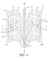
FIG. 4 is a portion of a directional tread pattern for a tire made in accordance with the present invention. -
FIG. 4A is a plan view of a tire employing the tread shown infigure 4 . -
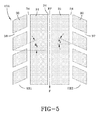
FIG. 5 is a portion of a directional tread pattern for a tire made in accordance with the present invention. -
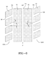
FIG. 6 is a portion of a non-directional tread made in accordance with the present invention. -
FIG. 7 is a chart showing the heel/toe wear performance of the shoulder tread elements, one graph showing the leading and trailing edges inclined with the axially outer tread edge portions entering and exiting the contact patch first atangles 0, -10, -20 and -30 and the other line showing the opposite shoulder similarly inclined but having the axially inner portions entering and exiting the contact patch first, this graphical depiction would apply to the non-directional tire offigure 6 . -
FIG. 8 is a chart showing the improved heel/toe wear of both shoulders as shown infigures 4 ,4A and5 of the directional tread which has the leading and trailing edges equal but oppositely oriented to reflect both shoulders tread elements having the axially outer portions of the leading and trailing edges entering and exiting the contact patch first. - With reference to
figure 4A , a pneumatic passenger orlight truck tire 10 made according to the present invention has atread 12 which has a plurality of tread elements defined by grooves around circumferentially and laterally around the tread between a pair of lateral tread edges TE to define a tread pattern. The presentinventive tread 12 is for passenger and light truck radial tires. Such radial tires are generally inflated to pressures under normal load in the range of 28 psi (193 kPa) to 45 psi (310 kPa). At these low pressures when the tires are lightly loaded the problems of heel and toe wear are most noticeable. By comparison heavy duty truck and bus tires operate at inflated pressures of 80 psi (552 kPa) to 120 psi (827 kPa) at much higher loads. Most of these tires avoid the heel/toe wear issues by using shoulder ribs for highway and paved road usage. Some tires have block elements in the shoulders on rear drive tires but front steer tires most typically use circumferentially continuous ribs to avoid vibration and tread wear issues generally. The present invention provides a design concept of superior performance in all wheel positions. - As shown in
figure 4A and4 , thetread 12 has a plurality of tread elements extending across the width of the tread between the lateral edges TE includingcentral tread elements elements 24ands 26 are identically shaped however oppositely oriented,tread element 28 is a central rib which is circumferentially continuous and extending about the circumference of the tire. Thetread 12 further has a pair of shoulder tread elements arranged in rows. The first row SH1, is defined bytread elements 20. The second shoulder row SH2 is defined bytread elements 22. These shoulder elements shapes and orientation are further defined bycircumferential grooves 14 on each half of thetread 12 as well as curvedlateral grooves 16 extending from a tread edge TE to the center portion of thetread 12 as shown. Thesegrooves 16 are curved in shape and extend along aline 50 form an apex 52 from the center of the tread element extending outwardly across the tread pattern changing direction along asecond line 50 adjacent theshoulder tread elements shoulder tread elements 20 each have aleading edge 21 and a trailingedge 23, while theshoulder elements 22 have aleading edge 25 and a trailingedge 27 as illustrated. - With further reference to
figure 4 , a footprint of a portion of thetread 12 is illustrated. The contact patch orfootprint 100 is shown in a dashed line which is generally rectangular in shape. This footprint shape or contact patch shape as shown is defined as somewhat squarish. A somewhat squarish footprint has a footprint shape factor of approximately 1.25 or less, preferably approaching 1. Had this footprint shape factor been more rounded, a footprint factor of 1.5 or more would have been exhibited, in such a case the central region would have been substantially longer in length while the lateral edges of the footprint would be shorter in length creating a more oval shape of the footprint. As illustrated, however, theexemplary tire 10 shows a more squarish footprint pattern. As illustrated, the leadingedge 21 of eachshoulder element 20 in the first shoulder region SH1 has an angle of the leading edge θ1, θ1 as shown is a straight line angle wherein the angle is measured from a perpendicular of the equatorial plane EP of the tire. The perpendicular line as shown, L, extends as either a line or a plane intersecting perpendicular to the equatorial plane. The angle θ1 as shown in theexemplary tire 10, preferably is 10 degrees or greater. On the opposite side of the tire the shoulder row SH2 hastread elements 22 wherein the leadingedge 25 exhibit an angle θ2. As illustrated the angle θ2 as measured from the line L to the leading edge is equal but opposite to the angle θ1 on the opposite shoulder. Both of these orientations ensure that as thetire 10 travels in a forward direction as indicated by the F onfigure 4 , the axially outer portions at the leading and trailing edge both enter and exit thecontact patch 100 prior to the axially inner portions of the leading and trailing edges. As such as thetire 10 rotates the outer portions of thetread 12 will first come into contact with thecontact patch 100 and as thetire 10 continues to rotate, this leading axially outer portion of either the trailing or leading edges will exit first while the axially inner portions of the leading and trailing edges will enter or leave the contact patch following these axially outer portions. Typically, and it is important to note that theaxially extending grooves 16 preferably have a width of at least 0.060 inches (1.524 mm) as defined by measuring perpendicularly between the leading and the trailing edges. This width ensures that thegroove 16 remains open as it passes through the footprint of thetire 10 and is not to be confused with a sipe, incision or other narrow groove which would tend to close up as thetire 10 enters or leaves the footprint of the tire. In this fashion the leading and trailing edges are neither supported by an adjacent element nor are there any other influences regarding the normal heel/toe wear that would be experienced. - Traditionally all season tires have these lateral grooves extending at approximately 0 degrees relative to the line L as they exited over the tread shoulder, this provided what was believed to be increased traction for the tire. As such the tread element was designed specifically so that these lateral grooves were always oriented at approximately 0 degrees. What has been determined however, is that 0 degrees is not an optimum orientation for leading or trailing edges of the
shoulder block elements figure 4 , the belief was that thelateral groove 16 should flare out and continue a flow pattern opposite to the direction of forward travel, so the water was ejected outward and not pushed back towards the center of the tread. This was particularly important it was believed in certain aqua-channel tires. What was determined however, and this study of the present invention has confirmed this actually enhances heel/toe wear and creates a pronounce negative effect with regard to abrasion occurring on leading and trailing edges of such shoulder block elements. - What is remarkable about the
lateral grooves 16 is that it not only flows over the shoulder but actually changes its orientation as it approaches the shoulder, such that thegroove 16 is oriented in a fashion that is opposite to the more central regions of thetread elements tread 12, however it has been found that theshoulder tread elements figures 4 ,4A and5 as will be discussed. These orientations while inclined such that the axially outer portions of thetread elements tire 10 as it relates to these inclinations. Historically 90 degrees was believed to create the maximum traction capabilities, however at 10 degrees or greater no significant drop-off in traction has been noted as the tire enters and leaves the footprint contact patch. - With reference to
figure 5 , atread pattern 12A is illustrated. Thetread pattern 12A as shown is very similar to that offigure 4 with the exception that the center tread elements are shown asribs 31 spaced by circumferentiallycontinuous grooves 34. This is done just for simplification purposes and this tire was actually carved to generate specific heel/toe wear performance data so that it could be compared with other orientations. The angles θ1 and θ2 are equal but oppositely oriented relative to the circumferential center plane or equatorial plane EP of the tire θ1 was carved at 0 degrees orientation or a standard all season type orientation of 0 degrees and at angles of -10, -20 and -30 degrees and test data was gathered with regard to heel/toe wear. Each tire was tested for over 8,000 miles and the amount of abrasion on the leading and trailing edges was measured. The average of those measurements was normalized and recorded as illustrated in chart 8. Thetread element 30 in the shoulder row SH1 as illustrated is spaced byinclined grooves 36 that intersect thecircumferential grooves 34. On the opposite side, shoulder row SH2 has thelateral grooves 37 defining thetread elements 33. As discussed, the orientation of the leading and trailing edges are equal but opposite such that an angle of inclination θ1 exists on the shoulder row SH1 whereas an angle θ2 equal but opposite exists on shoulder row SH2. In this example because the angle orientation is equal but opposite, each of the shoulder rows have a performance characteristic as defined in chart 8. As shown, the exemplary tire infigure 5 is directional such that it has a preferred forward direction of travel and therefore would always be mounted on a vehicle with a forward direction F. - With reference to
figure 6 , another exemplary tire is illustrated using the same reference numerals, however except for the shoulder rows SH2 wherein theshoulder elements 32 are defined bylateral grooves 38 which intersect thecircumferential grooves 34. In this case, both the shoulder elements SH1, SH2 have their leading and trailing edges of the shoulder elements inclined at an angle θ1, since both of the lateral grooves are extending in the same direction with the same orientation relative to the equatorial plane of the tire. In this case the tire is non-directional, has no preferred forward or rearward direction. Accordingly, a tire made in this example would be a conventional type tire with the exception of the angle θ1 on the shoulder SH1 as shown would enter or leave the footprint patch first on the axially outer portion of the leading and trailing edges whereas the shoulder elements SH2 on the right hand side of the figure would have the axially inner portions first entering and leaving the footprint patch as shown. In this example, the performance of the tread is exhibited in chart 7. Chart 7 has a pronounce difference between shoulder SH1 and shoulder SH2, in this fashion improved tread wear is found with thetread elements 30 on shoulder SH1, there is a dramatic reduction from having a 0 degree orientation, however, the combination of having θ1 equal and at the same orientation means that the axially inner portions of thetread elements 32 having inclinedgrooves 38 such that the leading and trailing edges on the axially inner portions of the leading and trailing edges enter the contact patch first means that the tread wear actually worsens such that heel/toe wear substantially be greater using this orientation, as such it was possible to notice that such an orientation while achieving a benefit on one shoulder SH1 would create an opposite detriment on the opposite shoulder SH2. While it was considered feasible to design such a tread, it is noted that one arguably could use angles between 0 and 10 degrees without a significant degradation and that rotation of the tire could permit for this type of tire to perform adequately. It is believed that such a non-directional tire may not be particularly useful or beneficial over a 0 degree conventional application. - With regard to non-directional tires, however, it is possible to achieve an asymmetric tire wherein a shoulder rib may be provided substantially similar to the prior art tire shown in
figures 1 and 2 of the prior art, however, thelateral grooves 36 could be oriented at θ1 using the present invention on one shoulder SH1. This would create an asymmetric tire having at least onetread element 30 using the inclination θ1 as shown wherein beneficial heel/toe results could be achieved wherein the axially outer portions of the leading or trailing edges of theshoulder elements 30 would enter the footprint first and exit first while the remaining portions of the tread remained in the footprint patch until exited after the axially outer portion. When this occurs beneficial results can occur with regard to the heel/toe wear as illustrated in the chart offigure 8 . - As shown from the charts it is clear that any orientation other than 0 degrees wherein the axially outer portion of the
shoulder tread element
Claims (15)
- A pneumatic tire having a radially outer tread (12), the tread (12) comprising a plurality of tread elements extending across the width of the tread between a pair of lateral edges, the plurality of tread elements including central tread elements (24, 26, 28) and shoulder tread elements (20, 22), the shoulder tread elements having leading edges (21, 25) and trailing tread edges (23, 27), wherein the shoulder tread elements (20, 22) are arranged in two rows (SH1, SH2), one row adjacent each lateral tread edge (TE), wherein at least one row of shoulder tread elements has the leading edges inclined relative to the direction of rotation of the tire in such a way that an axially outer portion of the leading edges of said row of shoulder tread elements enters and exits a footprint contact patch (100) prior to an axially inner portion of the leading edges of said row of shoulder tread elements.
- The tire of claim 1 wherein the central tread elements (24, 26, 28) are separated from the shoulder tread (23, 27) elements by circumferential grooves (14).
- The tire of at least one of the previous claims wherein the leading edges (21, 25) of the shoulder tread elements in one row of shoulder tread elements are oppositely directed, preferably equal but oppositely directed, relative to the leading edges (21, 25) of the shoulder tread elements in the other row of shoulder tread elements.
- The tire of at least one of the previous claims wherein the leading edges (21, 25) of the shoulder tread elements in both rows of shoulder tread elements are directionally oriented in the same direction, preferably equally directionally oriented in the same direction.
- The tire of at least one of the previous claims wherein the leading edges (21, 25) of the shoulder tread elements in at least one row of shoulder tread elements are inclined 10 degrees or greater, preferably in a range of from 10 degrees to 30 degrees, relative to a plane perpendicular to an equatorial center plane (EP) of the tire.
- The tire of at least one of the previous claims wherein the leading edges (21, 25) of the shoulder tread elements in one of the two rows of shoulder tread elements are inclined at a first angle (θ1) relative to a plane perpendicular to an equatorial center plane (EP) of the tire and the leading edges (21, 25) of the shoulder tread elements in the other of the two rows of shoulder tread elements are inclined at a second angle (θ2) relative to said plane perpendicular to the equatorial center plane (EP) of the tire, said first angle and said second angle being different.
- The tire of claim 6 wherein the first angle and the second angle are at least 3 degrees different, preferably from 5 to 10 degrees different.
- The tire of at least of the previous wherein a first line extending along the leading edges of laterally adjacent central tread elements has a generally "V" like or chevron shape, wherein the first line is located laterally inward of the lateral tread edges and extends to an apex (52), and wherein the apex (52) enters a contact patch of the tire as the tire rotates in a forward direction (F) prior to the remaining portions of the leading edges (21, 25) of the central tread elements.
- The tire of at least of the previous wherein the leading edges (21, 25) of the shoulder tread elements have an inclination directionally opposite to the leading edges of the central tread elements (24, 26, 28).
- The tire of claim 8 or 9 wherein a second line extending along the leading edge (21, 25) of the shoulder tread elements is connected to or flush with the first line.
- The tire of at least of the previous wherein the central tread elements have the apex (52) and axially inner portions of the central tread elements exit the contact patch (100) prior to axially outer portions of the central tread elements (24, 26, 28).
- The tire of at least of the previous wherein the tread (12) has an equatorial center plane (EP) and the apex (52) of the "V" like or chevron shape is centered on said center plane (EP), or wherein the tread (12) is asymmetrical having the apex (52) of the "V" like or chevron shape lying between a row of shoulder tread elements and an equatorial center plane (EP) of the tread.
- The tire of at least one of the previous claims having has a non-directional tread pattern.
- The tire of at least one of the previous claims 1-12 having a directional tread pattern.
- The tire of one of the previous claims wherein the tire is a passenger tire or a light truck tire.
Applications Claiming Priority (1)
| Application Number | Priority Date | Filing Date | Title |
|---|---|---|---|
| US12/193,295 US8261790B2 (en) | 2008-08-18 | 2008-08-18 | Directional tread for a tire |
Publications (2)
| Publication Number | Publication Date |
|---|---|
| EP2156968A1 true EP2156968A1 (en) | 2010-02-24 |
| EP2156968B1 EP2156968B1 (en) | 2016-04-20 |
Family
ID=41210646
Family Applications (1)
| Application Number | Title | Priority Date | Filing Date |
|---|---|---|---|
| EP09167702.1A Active EP2156968B1 (en) | 2008-08-18 | 2009-08-12 | An improved directional tread for a tire |
Country Status (2)
| Country | Link |
|---|---|
| US (1) | US8261790B2 (en) |
| EP (1) | EP2156968B1 (en) |
Cited By (2)
| Publication number | Priority date | Publication date | Assignee | Title |
|---|---|---|---|---|
| WO2015193805A1 (en) | 2014-06-19 | 2015-12-23 | Pirelli Tyre S.P.A. | Car tyre |
| IT202100014642A1 (en) | 2021-06-08 | 2022-12-08 | Pirelli | Tire for light truck wheels |
Families Citing this family (5)
| Publication number | Priority date | Publication date | Assignee | Title |
|---|---|---|---|---|
| JP5530059B2 (en) * | 2007-10-30 | 2014-06-25 | 株式会社ブリヂストン | Pneumatic tire |
| CN103052514B (en) * | 2010-08-05 | 2015-05-27 | 株式会社普利司通 | Tire |
| US20160121658A1 (en) | 2014-11-04 | 2016-05-05 | The Goodyear Tire & Rubber Company | Tread for a snow tire |
| US10279633B2 (en) | 2016-12-12 | 2019-05-07 | The Goodyear Tire & Rubber Company | Tread for a snow tire |
| US11701925B2 (en) | 2017-12-01 | 2023-07-18 | The Goodyear Tire & Rubber Company | Stabilizer structure for a tread of a tire |
Citations (11)
| Publication number | Priority date | Publication date | Assignee | Title |
|---|---|---|---|---|
| US4690189A (en) | 1986-01-29 | 1987-09-01 | The Goodyear Tire & Rubber Company | All-season pneumatic tire with chamfered tread blocks |
| US5176766A (en) | 1991-03-08 | 1993-01-05 | The Goodyear Tire & Rubber Company | Pneumatic tire having a unique footprint |
| US5503206A (en) | 1994-04-11 | 1996-04-02 | The Goodyear Tire & Rubber Company | Pneumatic tire having improved wet traction |
| JPH08142609A (en) * | 1994-11-18 | 1996-06-04 | Ohtsu Tire & Rubber Co Ltd :The | Pneumatic tire |
| US5538060A (en) | 1994-12-27 | 1996-07-23 | The Goodyear Tire & Rubber Company | Pneumatic tire having tread portion including blocks |
| DE19708613A1 (en) * | 1997-03-03 | 1998-09-10 | Sp Reifenwerke Gmbh | Tyre tread |
| EP0870630A2 (en) * | 1997-04-10 | 1998-10-14 | Bridgestone Corporation | Pneumatic tire |
| US5891276A (en) | 1996-10-28 | 1999-04-06 | The Yokohama Rubber Co., Ltd. | Pneumatic tire for heavy duty including narrow block |
| US5957179A (en) | 1993-11-03 | 1999-09-28 | The Goodyear Tire & Rubber Company | Pneumatic tire having improved wet traction |
| US6378583B1 (en) | 2000-02-28 | 2002-04-30 | The Goodyear Tire & Rubber Company | Heel and toe wear balancing |
| US6443199B1 (en) | 1997-09-17 | 2002-09-03 | The Goodyear Tire & Rubber Company | Footprints for nonrotatable automobile and light truck tires |
Family Cites Families (17)
| Publication number | Priority date | Publication date | Assignee | Title |
|---|---|---|---|---|
| US2642914A (en) * | 1951-09-28 | 1953-06-23 | Wingfoot Corp | Tire |
| IT1175345B (en) * | 1984-02-10 | 1987-07-01 | Pirelli | DIRECTIONAL TIRE FOR MOTOR VEHICLES |
| US4867219A (en) * | 1984-11-13 | 1989-09-19 | Wykoff Clyde R | Pneumatic tire and tire carcass having "directional" or "rotary strength imbalanced" high rigidity confluent belt ply assemblies and "directional tire operatioal characteristics" |
| US4722378A (en) * | 1986-05-19 | 1988-02-02 | The Goodyear Tire & Rubber Company | Tire treads with convex elements |
| US5002109A (en) * | 1989-05-25 | 1991-03-26 | The Goodyear Tire & Rubber Company | Symmetrical and directional pneumatic tire tread |
| JPH04110201A (en) * | 1990-08-30 | 1992-04-10 | Yokohama Rubber Co Ltd:The | Flat pneumatic tire for automobile |
| US5327952A (en) * | 1991-03-08 | 1994-07-12 | The Goodyear Tire & Rubber Company | Pneumatic tire having improved wet traction |
| US5746849A (en) * | 1995-12-11 | 1998-05-05 | The Goodyear Tire & Rubber Company | Tire tread including tie bar |
| US5733393A (en) * | 1996-01-17 | 1998-03-31 | The Goodyear Tire & Rubber Company | Tire having good diverse properties |
| EP1172235B1 (en) * | 2000-07-06 | 2006-09-13 | Sumitomo Rubber Industries Ltd. | Pneumatic tire |
| JP2004136856A (en) | 2002-10-21 | 2004-05-13 | Bridgestone Corp | Pneumatic tire |
| JP2005271644A (en) | 2004-03-23 | 2005-10-06 | Bridgestone Corp | Pneumatic tire |
| JP4437421B2 (en) | 2004-04-21 | 2010-03-24 | 株式会社ブリヂストン | Pneumatic tire |
| JP2006082633A (en) | 2004-09-15 | 2006-03-30 | Bridgestone Corp | Pneumatic tire |
| JP2006232012A (en) | 2005-02-23 | 2006-09-07 | Yokohama Rubber Co Ltd:The | Pneumatic tire |
| JP2007083822A (en) | 2005-09-21 | 2007-04-05 | Bridgestone Corp | Pneumatic tire |
| JP2007112228A (en) | 2005-10-19 | 2007-05-10 | Toyo Tire & Rubber Co Ltd | Pneumatic tire |
-
2008
- 2008-08-18 US US12/193,295 patent/US8261790B2/en not_active Expired - Fee Related
-
2009
- 2009-08-12 EP EP09167702.1A patent/EP2156968B1/en active Active
Patent Citations (12)
| Publication number | Priority date | Publication date | Assignee | Title |
|---|---|---|---|---|
| US4690189A (en) | 1986-01-29 | 1987-09-01 | The Goodyear Tire & Rubber Company | All-season pneumatic tire with chamfered tread blocks |
| US5176766A (en) | 1991-03-08 | 1993-01-05 | The Goodyear Tire & Rubber Company | Pneumatic tire having a unique footprint |
| US5176766B1 (en) | 1991-03-08 | 1996-04-30 | Goodyear Tire & Rubber | Pneumatic tire having a unique footprint |
| US5957179A (en) | 1993-11-03 | 1999-09-28 | The Goodyear Tire & Rubber Company | Pneumatic tire having improved wet traction |
| US5503206A (en) | 1994-04-11 | 1996-04-02 | The Goodyear Tire & Rubber Company | Pneumatic tire having improved wet traction |
| JPH08142609A (en) * | 1994-11-18 | 1996-06-04 | Ohtsu Tire & Rubber Co Ltd :The | Pneumatic tire |
| US5538060A (en) | 1994-12-27 | 1996-07-23 | The Goodyear Tire & Rubber Company | Pneumatic tire having tread portion including blocks |
| US5891276A (en) | 1996-10-28 | 1999-04-06 | The Yokohama Rubber Co., Ltd. | Pneumatic tire for heavy duty including narrow block |
| DE19708613A1 (en) * | 1997-03-03 | 1998-09-10 | Sp Reifenwerke Gmbh | Tyre tread |
| EP0870630A2 (en) * | 1997-04-10 | 1998-10-14 | Bridgestone Corporation | Pneumatic tire |
| US6443199B1 (en) | 1997-09-17 | 2002-09-03 | The Goodyear Tire & Rubber Company | Footprints for nonrotatable automobile and light truck tires |
| US6378583B1 (en) | 2000-02-28 | 2002-04-30 | The Goodyear Tire & Rubber Company | Heel and toe wear balancing |
Cited By (5)
| Publication number | Priority date | Publication date | Assignee | Title |
|---|---|---|---|---|
| WO2015193805A1 (en) | 2014-06-19 | 2015-12-23 | Pirelli Tyre S.P.A. | Car tyre |
| CN106660405A (en) * | 2014-06-19 | 2017-05-10 | 倍耐力轮胎股份公司 | Car tyre |
| US10486474B2 (en) | 2014-06-19 | 2019-11-26 | Pirelli Tyre S.P.A. | Car tyre |
| US11161374B2 (en) | 2014-06-19 | 2021-11-02 | Pirelli Tyre S.P.A. | Car tyre |
| IT202100014642A1 (en) | 2021-06-08 | 2022-12-08 | Pirelli | Tire for light truck wheels |
Also Published As
| Publication number | Publication date |
|---|---|
| US8261790B2 (en) | 2012-09-11 |
| EP2156968B1 (en) | 2016-04-20 |
| US20100038002A1 (en) | 2010-02-18 |
Similar Documents
| Publication | Publication Date | Title |
|---|---|---|
| US9751365B2 (en) | High mileage truck tire tread | |
| EP3017964A1 (en) | An improved tread for a snow tire | |
| US8210219B2 (en) | Pneumatic tire with tread having crown rib and middle ribs | |
| US9186935B2 (en) | Commercial truck steer tire tread | |
| EP2156968B1 (en) | An improved directional tread for a tire | |
| EP2546075B1 (en) | Tread for a pneumatic tire | |
| EP2631087B1 (en) | Pneumatic tire | |
| US10899178B2 (en) | Pneumatic tire | |
| US20080149237A1 (en) | Pneumatic tire | |
| US6378583B1 (en) | Heel and toe wear balancing | |
| US20110041973A1 (en) | Pneumatic tire | |
| CN108688411B (en) | Pneumatic tire | |
| AU2009230798A1 (en) | Pneumatic tire with asymmetric tread pattern | |
| CN102673318A (en) | Pneumatic tire | |
| US11241918B2 (en) | Pneumatic tire | |
| WO2017187740A1 (en) | Pneumatic tire | |
| WO2005005170A1 (en) | Pneumatic tire | |
| EP3332990B1 (en) | Tire tread for a snow tire | |
| CN115916554A (en) | Automobile tyre | |
| JP7464819B2 (en) | Pneumatic tires | |
| US11001103B2 (en) | Tread for a tire | |
| JPH04266505A (en) | Tire tread for winter months | |
| EP3670209B1 (en) | Tread for a pneumatic tire | |
| CN114423625A (en) | Tyre for vehicle wheels | |
| EP3894236A1 (en) | Tyre for vehicle wheels |
Legal Events
| Date | Code | Title | Description |
|---|---|---|---|
| PUAI | Public reference made under article 153(3) epc to a published international application that has entered the european phase |
Free format text: ORIGINAL CODE: 0009012 |
|
| AK | Designated contracting states |
Kind code of ref document: A1 Designated state(s): AT BE BG CH CY CZ DE DK EE ES FI FR GB GR HR HU IE IS IT LI LT LU LV MC MK MT NL NO PL PT RO SE SI SK SM TR |
|
| AX | Request for extension of the european patent |
Extension state: AL BA RS |
|
| 17P | Request for examination filed |
Effective date: 20100824 |
|
| 17Q | First examination report despatched |
Effective date: 20100916 |
|
| GRAP | Despatch of communication of intention to grant a patent |
Free format text: ORIGINAL CODE: EPIDOSNIGR1 |
|
| INTG | Intention to grant announced |
Effective date: 20151130 |
|
| GRAS | Grant fee paid |
Free format text: ORIGINAL CODE: EPIDOSNIGR3 |
|
| GRAA | (expected) grant |
Free format text: ORIGINAL CODE: 0009210 |
|
| AK | Designated contracting states |
Kind code of ref document: B1 Designated state(s): AT BE BG CH CY CZ DE DK EE ES FI FR GB GR HR HU IE IS IT LI LT LU LV MC MK MT NL NO PL PT RO SE SI SK SM TR |
|
| AX | Request for extension of the european patent |
Extension state: AL BA RS |
|
| REG | Reference to a national code |
Ref country code: GB Ref legal event code: FG4D |
|
| REG | Reference to a national code |
Ref country code: CH Ref legal event code: EP |
|
| REG | Reference to a national code |
Ref country code: AT Ref legal event code: REF Ref document number: 791992 Country of ref document: AT Kind code of ref document: T Effective date: 20160515 |
|
| REG | Reference to a national code |
Ref country code: IE Ref legal event code: FG4D |
|
| REG | Reference to a national code |
Ref country code: DE Ref legal event code: R096 Ref document number: 602009037908 Country of ref document: DE |
|
| REG | Reference to a national code |
Ref country code: FR Ref legal event code: PLFP Year of fee payment: 8 |
|
| REG | Reference to a national code |
Ref country code: LT Ref legal event code: MG4D |
|
| REG | Reference to a national code |
Ref country code: AT Ref legal event code: MK05 Ref document number: 791992 Country of ref document: AT Kind code of ref document: T Effective date: 20160420 |
|
| REG | Reference to a national code |
Ref country code: NL Ref legal event code: MP Effective date: 20160420 |
|
| PG25 | Lapsed in a contracting state [announced via postgrant information from national office to epo] |
Ref country code: NL Free format text: LAPSE BECAUSE OF FAILURE TO SUBMIT A TRANSLATION OF THE DESCRIPTION OR TO PAY THE FEE WITHIN THE PRESCRIBED TIME-LIMIT Effective date: 20160420 Ref country code: FI Free format text: LAPSE BECAUSE OF FAILURE TO SUBMIT A TRANSLATION OF THE DESCRIPTION OR TO PAY THE FEE WITHIN THE PRESCRIBED TIME-LIMIT Effective date: 20160420 Ref country code: NO Free format text: LAPSE BECAUSE OF FAILURE TO SUBMIT A TRANSLATION OF THE DESCRIPTION OR TO PAY THE FEE WITHIN THE PRESCRIBED TIME-LIMIT Effective date: 20160720 Ref country code: PL Free format text: LAPSE BECAUSE OF FAILURE TO SUBMIT A TRANSLATION OF THE DESCRIPTION OR TO PAY THE FEE WITHIN THE PRESCRIBED TIME-LIMIT Effective date: 20160420 Ref country code: LT Free format text: LAPSE BECAUSE OF FAILURE TO SUBMIT A TRANSLATION OF THE DESCRIPTION OR TO PAY THE FEE WITHIN THE PRESCRIBED TIME-LIMIT Effective date: 20160420 |
|
| PG25 | Lapsed in a contracting state [announced via postgrant information from national office to epo] |
Ref country code: AT Free format text: LAPSE BECAUSE OF FAILURE TO SUBMIT A TRANSLATION OF THE DESCRIPTION OR TO PAY THE FEE WITHIN THE PRESCRIBED TIME-LIMIT Effective date: 20160420 Ref country code: ES Free format text: LAPSE BECAUSE OF FAILURE TO SUBMIT A TRANSLATION OF THE DESCRIPTION OR TO PAY THE FEE WITHIN THE PRESCRIBED TIME-LIMIT Effective date: 20160420 Ref country code: LV Free format text: LAPSE BECAUSE OF FAILURE TO SUBMIT A TRANSLATION OF THE DESCRIPTION OR TO PAY THE FEE WITHIN THE PRESCRIBED TIME-LIMIT Effective date: 20160420 Ref country code: SE Free format text: LAPSE BECAUSE OF FAILURE TO SUBMIT A TRANSLATION OF THE DESCRIPTION OR TO PAY THE FEE WITHIN THE PRESCRIBED TIME-LIMIT Effective date: 20160420 Ref country code: HR Free format text: LAPSE BECAUSE OF FAILURE TO SUBMIT A TRANSLATION OF THE DESCRIPTION OR TO PAY THE FEE WITHIN THE PRESCRIBED TIME-LIMIT Effective date: 20160420 Ref country code: PT Free format text: LAPSE BECAUSE OF FAILURE TO SUBMIT A TRANSLATION OF THE DESCRIPTION OR TO PAY THE FEE WITHIN THE PRESCRIBED TIME-LIMIT Effective date: 20160822 Ref country code: GR Free format text: LAPSE BECAUSE OF FAILURE TO SUBMIT A TRANSLATION OF THE DESCRIPTION OR TO PAY THE FEE WITHIN THE PRESCRIBED TIME-LIMIT Effective date: 20160721 |
|
| PG25 | Lapsed in a contracting state [announced via postgrant information from national office to epo] |
Ref country code: BE Free format text: LAPSE BECAUSE OF FAILURE TO SUBMIT A TRANSLATION OF THE DESCRIPTION OR TO PAY THE FEE WITHIN THE PRESCRIBED TIME-LIMIT Effective date: 20160420 |
|
| REG | Reference to a national code |
Ref country code: DE Ref legal event code: R097 Ref document number: 602009037908 Country of ref document: DE |
|
| PG25 | Lapsed in a contracting state [announced via postgrant information from national office to epo] |
Ref country code: RO Free format text: LAPSE BECAUSE OF FAILURE TO SUBMIT A TRANSLATION OF THE DESCRIPTION OR TO PAY THE FEE WITHIN THE PRESCRIBED TIME-LIMIT Effective date: 20160420 Ref country code: DK Free format text: LAPSE BECAUSE OF FAILURE TO SUBMIT A TRANSLATION OF THE DESCRIPTION OR TO PAY THE FEE WITHIN THE PRESCRIBED TIME-LIMIT Effective date: 20160420 Ref country code: SK Free format text: LAPSE BECAUSE OF FAILURE TO SUBMIT A TRANSLATION OF THE DESCRIPTION OR TO PAY THE FEE WITHIN THE PRESCRIBED TIME-LIMIT Effective date: 20160420 Ref country code: CZ Free format text: LAPSE BECAUSE OF FAILURE TO SUBMIT A TRANSLATION OF THE DESCRIPTION OR TO PAY THE FEE WITHIN THE PRESCRIBED TIME-LIMIT Effective date: 20160420 Ref country code: EE Free format text: LAPSE BECAUSE OF FAILURE TO SUBMIT A TRANSLATION OF THE DESCRIPTION OR TO PAY THE FEE WITHIN THE PRESCRIBED TIME-LIMIT Effective date: 20160420 |
|
| PLBE | No opposition filed within time limit |
Free format text: ORIGINAL CODE: 0009261 |
|
| STAA | Information on the status of an ep patent application or granted ep patent |
Free format text: STATUS: NO OPPOSITION FILED WITHIN TIME LIMIT |
|
| PG25 | Lapsed in a contracting state [announced via postgrant information from national office to epo] |
Ref country code: SM Free format text: LAPSE BECAUSE OF FAILURE TO SUBMIT A TRANSLATION OF THE DESCRIPTION OR TO PAY THE FEE WITHIN THE PRESCRIBED TIME-LIMIT Effective date: 20160420 |
|
| 26N | No opposition filed |
Effective date: 20170123 |
|
| PG25 | Lapsed in a contracting state [announced via postgrant information from national office to epo] |
Ref country code: MC Free format text: LAPSE BECAUSE OF FAILURE TO SUBMIT A TRANSLATION OF THE DESCRIPTION OR TO PAY THE FEE WITHIN THE PRESCRIBED TIME-LIMIT Effective date: 20160420 |
|
| REG | Reference to a national code |
Ref country code: CH Ref legal event code: PL |
|
| GBPC | Gb: european patent ceased through non-payment of renewal fee |
Effective date: 20160812 |
|
| PG25 | Lapsed in a contracting state [announced via postgrant information from national office to epo] |
Ref country code: CH Free format text: LAPSE BECAUSE OF NON-PAYMENT OF DUE FEES Effective date: 20160831 Ref country code: LI Free format text: LAPSE BECAUSE OF NON-PAYMENT OF DUE FEES Effective date: 20160831 |
|
| PG25 | Lapsed in a contracting state [announced via postgrant information from national office to epo] |
Ref country code: SI Free format text: LAPSE BECAUSE OF FAILURE TO SUBMIT A TRANSLATION OF THE DESCRIPTION OR TO PAY THE FEE WITHIN THE PRESCRIBED TIME-LIMIT Effective date: 20160420 |
|
| REG | Reference to a national code |
Ref country code: IE Ref legal event code: MM4A |
|
| REG | Reference to a national code |
Ref country code: FR Ref legal event code: PLFP Year of fee payment: 9 |
|
| PG25 | Lapsed in a contracting state [announced via postgrant information from national office to epo] |
Ref country code: GB Free format text: LAPSE BECAUSE OF NON-PAYMENT OF DUE FEES Effective date: 20160812 Ref country code: IE Free format text: LAPSE BECAUSE OF NON-PAYMENT OF DUE FEES Effective date: 20160812 |
|
| PG25 | Lapsed in a contracting state [announced via postgrant information from national office to epo] |
Ref country code: LU Free format text: LAPSE BECAUSE OF NON-PAYMENT OF DUE FEES Effective date: 20160812 |
|
| PGFP | Annual fee paid to national office [announced via postgrant information from national office to epo] |
Ref country code: IT Payment date: 20170817 Year of fee payment: 9 Ref country code: DE Payment date: 20170825 Year of fee payment: 9 Ref country code: FR Payment date: 20170720 Year of fee payment: 9 |
|
| PG25 | Lapsed in a contracting state [announced via postgrant information from national office to epo] |
Ref country code: HU Free format text: LAPSE BECAUSE OF FAILURE TO SUBMIT A TRANSLATION OF THE DESCRIPTION OR TO PAY THE FEE WITHIN THE PRESCRIBED TIME-LIMIT; INVALID AB INITIO Effective date: 20090812 Ref country code: CY Free format text: LAPSE BECAUSE OF FAILURE TO SUBMIT A TRANSLATION OF THE DESCRIPTION OR TO PAY THE FEE WITHIN THE PRESCRIBED TIME-LIMIT Effective date: 20160420 |
|
| PG25 | Lapsed in a contracting state [announced via postgrant information from national office to epo] |
Ref country code: TR Free format text: LAPSE BECAUSE OF FAILURE TO SUBMIT A TRANSLATION OF THE DESCRIPTION OR TO PAY THE FEE WITHIN THE PRESCRIBED TIME-LIMIT Effective date: 20160420 Ref country code: MK Free format text: LAPSE BECAUSE OF FAILURE TO SUBMIT A TRANSLATION OF THE DESCRIPTION OR TO PAY THE FEE WITHIN THE PRESCRIBED TIME-LIMIT Effective date: 20160420 Ref country code: IS Free format text: LAPSE BECAUSE OF FAILURE TO SUBMIT A TRANSLATION OF THE DESCRIPTION OR TO PAY THE FEE WITHIN THE PRESCRIBED TIME-LIMIT Effective date: 20160420 Ref country code: MT Free format text: LAPSE BECAUSE OF NON-PAYMENT OF DUE FEES Effective date: 20160831 |
|
| PG25 | Lapsed in a contracting state [announced via postgrant information from national office to epo] |
Ref country code: BG Free format text: LAPSE BECAUSE OF FAILURE TO SUBMIT A TRANSLATION OF THE DESCRIPTION OR TO PAY THE FEE WITHIN THE PRESCRIBED TIME-LIMIT Effective date: 20160420 |
|
| REG | Reference to a national code |
Ref country code: DE Ref legal event code: R119 Ref document number: 602009037908 Country of ref document: DE |
|
| PG25 | Lapsed in a contracting state [announced via postgrant information from national office to epo] |
Ref country code: IT Free format text: LAPSE BECAUSE OF NON-PAYMENT OF DUE FEES Effective date: 20180812 Ref country code: DE Free format text: LAPSE BECAUSE OF NON-PAYMENT OF DUE FEES Effective date: 20190301 |
|
| PG25 | Lapsed in a contracting state [announced via postgrant information from national office to epo] |
Ref country code: FR Free format text: LAPSE BECAUSE OF NON-PAYMENT OF DUE FEES Effective date: 20180831 |