EP2156908A1 - Mandrel mill and process for manufacturing seamless pipe - Google Patents
Mandrel mill and process for manufacturing seamless pipe Download PDFInfo
- Publication number
- EP2156908A1 EP2156908A1 EP08702931A EP08702931A EP2156908A1 EP 2156908 A1 EP2156908 A1 EP 2156908A1 EP 08702931 A EP08702931 A EP 08702931A EP 08702931 A EP08702931 A EP 08702931A EP 2156908 A1 EP2156908 A1 EP 2156908A1
- Authority
- EP
- European Patent Office
- Prior art keywords
- rolling
- mandrel mill
- pipe
- rolling stand
- roll diameter
- Prior art date
- Legal status (The legal status is an assumption and is not a legal conclusion. Google has not performed a legal analysis and makes no representation as to the accuracy of the status listed.)
- Granted
Links
Images

Classifications
-
- B—PERFORMING OPERATIONS; TRANSPORTING
- B21—MECHANICAL METAL-WORKING WITHOUT ESSENTIALLY REMOVING MATERIAL; PUNCHING METAL
- B21B—ROLLING OF METAL
- B21B17/00—Tube-rolling by rollers of which the axes are arranged essentially perpendicular to the axis of the work, e.g. "axial" tube-rolling
- B21B17/02—Tube-rolling by rollers of which the axes are arranged essentially perpendicular to the axis of the work, e.g. "axial" tube-rolling with mandrel, i.e. the mandrel rod contacts the rolled tube over the rod length
-
- B—PERFORMING OPERATIONS; TRANSPORTING
- B21—MECHANICAL METAL-WORKING WITHOUT ESSENTIALLY REMOVING MATERIAL; PUNCHING METAL
- B21B—ROLLING OF METAL
- B21B17/00—Tube-rolling by rollers of which the axes are arranged essentially perpendicular to the axis of the work, e.g. "axial" tube-rolling
- B21B17/02—Tube-rolling by rollers of which the axes are arranged essentially perpendicular to the axis of the work, e.g. "axial" tube-rolling with mandrel, i.e. the mandrel rod contacts the rolled tube over the rod length
- B21B17/04—Tube-rolling by rollers of which the axes are arranged essentially perpendicular to the axis of the work, e.g. "axial" tube-rolling with mandrel, i.e. the mandrel rod contacts the rolled tube over the rod length in a continuous process
-
- B—PERFORMING OPERATIONS; TRANSPORTING
- B21—MECHANICAL METAL-WORKING WITHOUT ESSENTIALLY REMOVING MATERIAL; PUNCHING METAL
- B21B—ROLLING OF METAL
- B21B13/00—Metal-rolling stands, i.e. an assembly composed of a stand frame, rolls, and accessories
- B21B13/08—Metal-rolling stands, i.e. an assembly composed of a stand frame, rolls, and accessories with differently-directed roll axes, e.g. for the so-called "universal" rolling process
- B21B13/10—Metal-rolling stands, i.e. an assembly composed of a stand frame, rolls, and accessories with differently-directed roll axes, e.g. for the so-called "universal" rolling process all axes being arranged in one plane
- B21B13/103—Metal-rolling stands, i.e. an assembly composed of a stand frame, rolls, and accessories with differently-directed roll axes, e.g. for the so-called "universal" rolling process all axes being arranged in one plane for rolling bars, rods or wire
-
- B—PERFORMING OPERATIONS; TRANSPORTING
- B21—MECHANICAL METAL-WORKING WITHOUT ESSENTIALLY REMOVING MATERIAL; PUNCHING METAL
- B21B—ROLLING OF METAL
- B21B27/00—Rolls, roll alloys or roll fabrication; Lubricating, cooling or heating rolls while in use
- B21B27/02—Shape or construction of rolls
- B21B27/024—Rolls for bars, rods, rounds, tubes, wire or the like
Definitions
- the present invention relates to a mandrel mill and a method for manufacturing a seamless pipe or tube using the same, and particularly relates to a mandrel mill that is capable of not only enhancing a elongation ratio of a pipe or tube, but also suppressing occurrence of a pinhole defect and a method for manufacturing the seamless pipe or tube using the same.
- a mandrel mill which is a piece of equipment for manufacturing a seamless pipe or tube
- a 2-roll type mandrel mill in which two grooved rolls opposed are disposed in each rolling stand, and between adjacent rolling stands, the rolling directions of the grooved rolls are alternately arranged, being 90° shifted
- a 3-roll type mandrel mill in which three grooved rolls are disposed in each rolling stand such that the angle formed by the rolling directions of the grooved rolls is 120°, and between adjacent rolling stands, the rolling directions of the grooved rolls are alternately arranged, being 60° shifted.
- pipe or tube is referred to as "pipe” when deemed appropriate.
- the elongation ratio of a pipe for a mandrel mill i.e., the ratio of wall thickness of the pipe on the inlet side of the mandrel mill to that on the outlet side thereof
- the elongation ratio of the pipe be enhanced as much as possible. This is because, if the elongation ratio of the pipe is enhanced, a pipe with a longer length can be obtained by drawing and rolling, and thus more product stocks can be obtained in one step of drawing and rolling.
- the wall thickness rolling reduction rate for each of the rolling stands (especially for the upstream rolling stands) is set at a high value.
- the wall thickness rolling reduction rate is set at too high a value, there arises a possibility that a through-hole called a pinhole defect occurs in a portion of the pipe that is opposed to the flange of the grooved roll, resulting from such a cause as the flow (metal flow) of the pipe material which is rolled at the groove bottom of the grooved roll being not sufficiently spread to the flange side of the grooved roll.
- a mandrel mill for example, a mandrel mill provided with five rolling stands, the elongation ratio of the pipe is generally held to under 4. Therefore, a mandrel mill which allows the elongation ratio of the pipe to be further enhanced for increasing the efficiency of manufacturing a seamless pipe has been demanded.
- the present invention has been made in view of such a problem with the prior art, and it is a subject of the present invention to provide a mandrel mill that is capable of not only enhancing the elongation ratio of the pipe, but also suppressing a pinhole defect from occurring and a method for manufacturing a seamless pipe using the same.
- the present inventor has made a keen study, and has found the fact that, if the roll diameter for the first rolling stand and the second rolling stand is increased to a predetermined value or over (accordingly, if the roll diameter ratio is increased to a predetermined value or over), not only the elongation ratio of the pipe or tube can be enhanced, but also occurrence of a pinhole defect can be suppressed.
- the present invention has been completed on the basis of such a new finding of the present inventor.
- the first means of the present invention provides a mandrel mill comprising a plurality of rolling stands in which two grooved rolls are disposed, respectively, the mandrel mill being characterized in that the roll diameter ratio for the first rolling stand and the second rolling stand is set at a value of 4.6 or over.
- first rolling stand in the first means refers to a rolling stand which is disposed first when counted from the inlet side of the mandrel mill.
- second rolling stand in the first means refers to a rolling stand which is disposed second when counted from the inlet side of the mandrel mill.
- roll diameter ratio for the first means refers to a ratio expressed by D R /D C , where D R is the roll diameter (the smallest roll diameter) at the groove bottom of each grooved roll which is disposed in the rolling stand, and D C is the distance between the groove bottoms of the grooved rolls.
- the second means of the present invention provides a mandrel mill comprising a plurality of rolling stands in which three grooved rolls are disposed, respectively, the mandrel mill being characterized in that the roll diameter ratio for the first rolling stand and the second rolling stand is set at a value of 2.8 or over.
- the meanings of the "first rolling stand” and the “second rolling stand” for the second means are the same as those for the first means that are described above.
- the “roll diameter ratio” for the second means refers to a ratio expressed by D R /D C , where D R is the roll diameter (the smallest roll diameter) at the groove bottom of each grooved roll which is disposed in the rolling stand, and D C /2 is the distance between the groove bottom of each grooved roll and the pass center.
- the present invention provides a method for manufacturing a seamless pipe or tube, the method being characterized by comprising the step of drawing and rolling a pipe or tube using the mandrel mill according to the first means or the second means.
- the elongation ratio of the pipe or tube can be enhanced, but also occurrence of a pinhole defect can be suppressed. Therefore, the efficiency of manufacturing a seamless pipe or tube can be increased without causing poor-quality rolling.
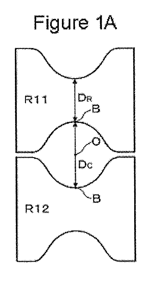
- Figure 1A is a longitudinal sectional view illustrating a schematic configuration of a rolling stand constituting a two-roll type mandrel mill according to a first embodiment of the present invention.
- a mandrel mill according to the present embodiment comprises a plurality of rolling stands in which two grooved rolls R11 and R12 are disposed.
- the mandrel mill is characterized in that the roll diameter ratio D R /D C for the first rolling stand and the second rolling stand is set at a value of 4.6 or over.
- the roll diameter ratio may be set at a value which has been conventionally used (for example, 3 or under).
- the reason why the roll diameter ratio D R /D C for the first rolling stand and the second rolling stand is set at a value of 4.6 or over will be explained with reference to Figure 1B .
- Figure 1B is a graph obtained by plotting the lower limit values of roll diameter ratio with which no pinhole defects occurred in a pipe when drawing and rolling thereof was performed with the wall thickness rolling reduction rate of the pipe and the roll diameter ratio being set at various values in the first rolling stand and the second rolling stand of the mandrel mill according to the first embodiment.
- the graph shown in Figure 1B indicates that, if the wall thickness rolling reduction rate and the roll diameter ratio are set at a value in the region under an approximate straight line L shown in Figure 1B , a pinhole defect will occur in the pipe, while, if the wall thickness rolling reduction rate and the roll diameter ratio are set at a value in the region above the approximate straight line L, no pinhole defect will occur in the pipe.
- the wall thickness rolling reduction rate which is represented by the abscissa in Figure 1B , is a rate defined by the following formula (1):
- t i1 is the wall thickness of the pipe on the inlet side of the first rolling stand
- t o2 is the wall thickness of the pipe on the outlet side of the second rolling stand.
- the roll diameter ratio D R /D C for the first rolling stand and the second rolling stand of the mandrel mill according to the present embodiment is set at a value of 4.6 or over.
- the mandrel mill according to the present embodiment not only the elongation ratio of the pipe can be enhanced, but also occurrence of a pinhole defect can be suppressed.
- the roll diameter ratio D R /D C being increased (the roll diameter D R being increased), the length of contact made between the pipe which is being subjected to drawing and rolling and the grooved roll R11, R12 (the contact length of the pipe along the direction of axis thereof) is increased.
- FIG. 2A is a longitudinal sectional view illustrating a schematic configuration of a rolling stand constituting a three-roll type mandrel mill according to a second embodiment of the present invention.
- a mandrel mill according to the present embodiment comprises a plurality of rolling stands in which three grooved rolls R21 R22 and R23 are disposed.
- the mandrel mill is characterized in that the roll diameter ratio D R /D C for the first rolling stand and the second rolling stand is set at a value of 2.8 or over.
- the roll diameter ratio may be set at a value which has been conventionally used (for example, 3 or under).
- the reason why the roll diameter ratio D R /D C for the first rolling stand and the second rolling stand is set at a value of 2.8 or over will be explained with reference to Figure 2B .
- Figure 2B is a graph obtained by plotting the lower limit values of roll diameter ratio with which no pinhole defects occurred in a pipe when drawing and rolling thereof was performed with the wall thickness rolling reduction rate of the pipe and the roll diameter ratio being set at various values in the first rolling stand and the second rolling stand of the mandrel mill according to the second embodiment.
- the graph shown in Figure 2B indicates that, if the wall thickness rolling reduction rate and the roll diameter ratio are set at a value in the region under an approximate straight line L shown in Figure 2B , a pinhole defect will occur in the pipe, while, if the wall thickness rolling reduction rate and the roll diameter ratio are set at a value in the region above the approximate straight line L, no pinhole defect will occur in the pipe.
- the wall thickness rolling reduction rate which is represented by the abscissa in Figure 2B , is a rate defined by the above formula (1), as the first embodiment.
- the roll diameter ratio D R /D C for the first rolling stand and the second rolling stand of the mandrel mill according to the present embodiment is set at a value of 2.8 or over.
- the mandrel mill according to the present embodiment not only the elongation ratio of the pipe can be enhanced, but also occurrence of a pinhole defect can be suppressed.
- the roll diameter ratio D R /D C being increased (the roll diameter D R being increased), the length of contact made between the pipe which is being subjected to drawing and rolling and the grooved roll R21, R22 and R23 (the contact length of the pipe along the direction of axis thereof) is increased.
- the roll diameter ratio D R /D C for the first rolling stand and the second rolling stand is set at too high a value (the roll diameter D R is set at too high a value)
- grooved rolls having a large diameter will be required, resulting in an increased equipment cost.
- the distance between rolling stands (the distance from the first rolling stand to the second rolling stand and that from the second rolling stand to the third rolling stand) will be increased, resulting in the length of the non-steady portion of the pipe end (the portion of the pipe end that is subjected to drawing and rolling with both pipe ends being not constrained by the grooved rolls) being increased, which may deteriorate the quality of the pipe.
- the roll diameter ratio D R /D C for the first rolling stand and the second rolling stand be set at a value as close to the lower limit value as possible.
Landscapes
- Engineering & Computer Science (AREA)
- Mechanical Engineering (AREA)
- Reduction Rolling/Reduction Stand/Operation Of Reduction Machine (AREA)
- Control Of Metal Rolling (AREA)
- Extrusion Moulding Of Plastics Or The Like (AREA)
Abstract
Description
- The present invention relates to a mandrel mill and a method for manufacturing a seamless pipe or tube using the same, and particularly relates to a mandrel mill that is capable of not only enhancing a elongation ratio of a pipe or tube, but also suppressing occurrence of a pinhole defect and a method for manufacturing the seamless pipe or tube using the same.
- As a mandrel mill, which is a piece of equipment for manufacturing a seamless pipe or tube, there have been conventionally used a 2-roll type mandrel mill in which two grooved rolls opposed are disposed in each rolling stand, and between adjacent rolling stands, the rolling directions of the grooved rolls are alternately arranged, being 90° shifted, and also a 3-roll type mandrel mill in which three grooved rolls are disposed in each rolling stand such that the angle formed by the rolling directions of the grooved rolls is 120°, and between adjacent rolling stands, the rolling directions of the grooved rolls are alternately arranged, being 60° shifted. Hereinafter, "pipe or tube "is referred to as "pipe" when deemed appropriate.
- Herein, in order to enhance the efficiency of manufacturing a seamless pipe, it is desirable that the elongation ratio of a pipe for a mandrel mill (i.e., the ratio of wall thickness of the pipe on the inlet side of the mandrel mill to that on the outlet side thereof) be enhanced as much as possible. This is because, if the elongation ratio of the pipe is enhanced, a pipe with a longer length can be obtained by drawing and rolling, and thus more product stocks can be obtained in one step of drawing and rolling.
- In order to enhance the elongation ratio of the pipe for a mandrel mill, it can be conceived, for example, that the wall thickness rolling reduction rate for each of the rolling stands (especially for the upstream rolling stands) is set at a high value. However, if the wall thickness rolling reduction rate is set at too high a value, there arises a possibility that a through-hole called a pinhole defect occurs in a portion of the pipe that is opposed to the flange of the grooved roll, resulting from such a cause as the flow (metal flow) of the pipe material which is rolled at the groove bottom of the grooved roll being not sufficiently spread to the flange side of the grooved roll. Alternatively, for enhancing the elongation ratio of the pipe, it can be conceived to increase the number of rolling stands without setting the wall thickness rolling reduction rate for each of the rolling stands at too high a value. However, increasing the number of rolling stands will increase the equipment cost in proportion, and also require increased manpower for maintenance, thus a practical number of rolling stands is said to be about 5 to 8. Thus, with the conventional mandrel mill, for example, a mandrel mill provided with five rolling stands, the elongation ratio of the pipe is generally held to under 4. Therefore, a mandrel mill which allows the elongation ratio of the pipe to be further enhanced for increasing the efficiency of manufacturing a seamless pipe has been demanded.
- The present invention has been made in view of such a problem with the prior art, and it is a subject of the present invention to provide a mandrel mill that is capable of not only enhancing the elongation ratio of the pipe, but also suppressing a pinhole defect from occurring and a method for manufacturing a seamless pipe using the same.
- In order to solve the aforementioned subject, the present inventor has made a keen study, and has found the fact that, if the roll diameter for the first rolling stand and the second rolling stand is increased to a predetermined value or over (accordingly, if the roll diameter ratio is increased to a predetermined value or over), not only the elongation ratio of the pipe or tube can be enhanced, but also occurrence of a pinhole defect can be suppressed. The present invention has been completed on the basis of such a new finding of the present inventor.
- Namely, the first means of the present invention provides a mandrel mill comprising a plurality of rolling stands in which two grooved rolls are disposed, respectively, the mandrel mill being characterized in that the roll diameter ratio for the first rolling stand and the second rolling stand is set at a value of 4.6 or over.
- The "first rolling stand" in the first means refers to a rolling stand which is disposed first when counted from the inlet side of the mandrel mill. Likewise, the "second rolling stand" in the first means refers to a rolling stand which is disposed second when counted from the inlet side of the mandrel mill. In addition, the "roll diameter ratio" for the first means refers to a ratio expressed by DR/DC, where DR is the roll diameter (the smallest roll diameter) at the groove bottom of each grooved roll which is disposed in the rolling stand, and DC is the distance between the groove bottoms of the grooved rolls.
- Also, the second means of the present invention provides a mandrel mill comprising a plurality of rolling stands in which three grooved rolls are disposed, respectively, the mandrel mill being characterized in that the roll diameter ratio for the first rolling stand and the second rolling stand is set at a value of 2.8 or over.
- The meanings of the "first rolling stand" and the "second rolling stand" for the second means are the same as those for the first means that are described above. In addition, the "roll diameter ratio" for the second means refers to a ratio expressed by DR/DC, where DR is the roll diameter (the smallest roll diameter) at the groove bottom of each grooved roll which is disposed in the rolling stand, and DC/2 is the distance between the groove bottom of each grooved roll and the pass center.
- Further, in order to solve the aforementioned subject, the present invention provides a method for manufacturing a seamless pipe or tube, the method being characterized by comprising the step of drawing and rolling a pipe or tube using the mandrel mill according to the first means or the second means.
- According to the present invention, not only the elongation ratio of the pipe or tube can be enhanced, but also occurrence of a pinhole defect can be suppressed. Therefore, the efficiency of manufacturing a seamless pipe or tube can be increased without causing poor-quality rolling.
-
-
Figure 1A is a longitudinal sectional view illustrating a schematic configuration of a rolling stand constituting a two-roll type mandrel mill according to a first embodiment of the present invention; -
Figure 1B is a graph obtained by plotting the lower limit values of roll diameter ratio with which no pinhole defects occurred in a pipe when drawing and rolling thereof was performed with the wall thickness rolling reduction rate of the pipe and the roll diameter ratio being set at various values in the first rolling stand and the second rolling stand of the mandrel mill according to the first embodiment of the present invention; -
Figure 2A is a longitudinal sectional view illustrating a schematic configuration of a rolling stand constituting a three-roll type mandrel mill according to a second embodiment of the present invention; and -
Figure 2B is a graph obtained by plotting the lower limit values of roll diameter ratio with which no pinhole defects occurred in a pipe when drawing and rolling thereof was performed with the wall thickness rolling reduction rate of the pipe and the roll diameter ratio being set at various values in the first rolling stand and the second rolling stand of the mandrel mill according to the second embodiment of the present invention. - Hereinbelow, embodiments of the present invention will be explained with appropriate reference to the attached drawings.
-
Figure 1A is a longitudinal sectional view illustrating a schematic configuration of a rolling stand constituting a two-roll type mandrel mill according to a first embodiment of the present invention. As shown inFigure 1A , a mandrel mill according to the present embodiment comprises a plurality of rolling stands in which two grooved rolls R11 and R12 are disposed. And, the mandrel mill is characterized in that the roll diameter ratio DR/DC for the first rolling stand and the second rolling stand is set at a value of 4.6 or over. - In other words, as shown in
Figure 1A , if the roll diameter (the smallest roll diameter) at the groove bottom B of each grooved roll R11, R12 which is disposed in the first rolling stand is DR, and the distance between the groove bottoms B of the grooved rolls R11, R12 is DC, the roll diameter ratio expressed by DR/DC is set at 4.6 or over. This description is also applicable to the second rolling stand. For the other rolling stands (for example, a third rolling stand to a fifth rolling stand in case where the mandrel mill according to the present embodiment comprises five rolling stands in total), there is no need for setting the roll diameter ratio at the above-mentioned value, but the roll diameter ratio may be set at a value which has been conventionally used (for example, 3 or under). Hereinbelow, the reason why the roll diameter ratio DR/DC for the first rolling stand and the second rolling stand is set at a value of 4.6 or over will be explained with reference toFigure 1B . -
Figure 1B is a graph obtained by plotting the lower limit values of roll diameter ratio with which no pinhole defects occurred in a pipe when drawing and rolling thereof was performed with the wall thickness rolling reduction rate of the pipe and the roll diameter ratio being set at various values in the first rolling stand and the second rolling stand of the mandrel mill according to the first embodiment. In other words, the graph shown inFigure 1B indicates that, if the wall thickness rolling reduction rate and the roll diameter ratio are set at a value in the region under an approximate straight line L shown inFigure 1B , a pinhole defect will occur in the pipe, while, if the wall thickness rolling reduction rate and the roll diameter ratio are set at a value in the region above the approximate straight line L, no pinhole defect will occur in the pipe. The wall thickness rolling reduction rate, which is represented by the abscissa inFigure 1B , is a rate defined by the following formula (1):
where ti1 is the wall thickness of the pipe on the inlet side of the first rolling stand and to2 is the wall thickness of the pipe on the outlet side of the second rolling stand. - Herein, ti1/to2, which is a reciprocal of to2/ti1 given on the right side of the above formula (1), provides a value corresponding to the elongation ratio of the pipe for the first rolling stand and the second rolling stand.
If this ti1/to2 is set at a value of at least 4, the value of the elongation ratio of the pipe (the ratio of wall thickness of the pipe on the inlet side of mandrel mill to that on the outlet side thereof) for the entire mandrel mill will be 4 or over, which is larger than conventional. When ti1/to2 = 4, the wall thickness rolling reduction rate defined by the above formula (1) will be 0.75. And, as can be seen fromFigure 1B , when the wall thickness rolling reduction rate = 0.75, setting the roll diameter ratio DR/DC at a value of 4.6 or over will allow occurrence of a pinhole defect to be suppressed. In other words, if the roll diameter ratio DR/DC is set at a value of 4.6 or over, not only the elongation ratio of the pipe for the first rolling stand and the second rolling stand can be enhanced to 4 (accordingly, the elongation ratio of the pipe for the entire mandrel mill can be enhanced to a value of 4 or over, which is larger than conventional), but also occurrence of a pinhole defect can be suppressed. - From the reason as described above, the roll diameter ratio DR/DC for the first rolling stand and the second rolling stand of the mandrel mill according to the present embodiment is set at a value of 4.6 or over. Thereby, with the mandrel mill according to the present embodiment, not only the elongation ratio of the pipe can be enhanced, but also occurrence of a pinhole defect can be suppressed. With the roll diameter ratio DR/DC being increased (the roll diameter DR being increased), the length of contact made between the pipe which is being subjected to drawing and rolling and the grooved roll R11, R12 (the contact length of the pipe along the direction of axis thereof) is increased. It can therefore be considered that, even if the elongation ratio (the wall thickness rolling reduction rate) is set at a high value, the flow (metal flow) of the pipe material is sufficiently spread to the flange side of the grooved roll R11, R12 during the drawing and rolling, whereby occurrence of a pinhole defect can be suppressed.
-
Figure 2A is a longitudinal sectional view illustrating a schematic configuration of a rolling stand constituting a three-roll type mandrel mill according to a second embodiment of the present invention. As shown inFigure 2A , a mandrel mill according to the present embodiment comprises a plurality of rolling stands in which three grooved rolls R21 R22 and R23 are disposed. And, the mandrel mill is characterized in that the roll diameter ratio DR/DC for the first rolling stand and the second rolling stand is set at a value of 2.8 or over. - In other words, as shown in
Figure 2A , if the roll diameter (the smallest roll diameter) at the groove bottom B of each grooved roll R21 to R23 which is disposed in the first rolling stand is DR, and the distance between the groove bottom B of each grooved roll R21 to R23 and the pass center O (the pass line center for the pipe as the workpiece) is DC/2, the roll diameter ratio expressed by DR/DC is set at 2.8 or over. This description is also applicable to the second rolling stand. For the other rolling stands (for example, a third rolling stand to a fifth rolling stand in case where the mandrel mill according to the present embodiment comprises five rolling stands in total), there is no need for setting the roll diameter ratio at the above-mentioned value, but the roll diameter ratio may be set at a value which has been conventionally used (for example, 3 or under). Hereinbelow, the reason why the roll diameter ratio DR/DC for the first rolling stand and the second rolling stand is set at a value of 2.8 or over will be explained with reference toFigure 2B . -
Figure 2B is a graph obtained by plotting the lower limit values of roll diameter ratio with which no pinhole defects occurred in a pipe when drawing and rolling thereof was performed with the wall thickness rolling reduction rate of the pipe and the roll diameter ratio being set at various values in the first rolling stand and the second rolling stand of the mandrel mill according to the second embodiment. In other words, the graph shown inFigure 2B indicates that, if the wall thickness rolling reduction rate and the roll diameter ratio are set at a value in the region under an approximate straight line L shown inFigure 2B , a pinhole defect will occur in the pipe, while, if the wall thickness rolling reduction rate and the roll diameter ratio are set at a value in the region above the approximate straight line L, no pinhole defect will occur in the pipe. The wall thickness rolling reduction rate, which is represented by the abscissa inFigure 2B , is a rate defined by the above formula (1), as the first embodiment. - And, as can be seen from
Figure 2B , when the wall thickness rolling reduction rate = 0.75, setting the roll diameter ratio DR/DC at a value of 2.8 or over will allow occurrence of a pinhole defect to be suppressed. In other words, if the roll diameter ratio DR/DC is set at a value of 2.8 or over, not only the elongation ratio of the pipe for the first rolling stand and the second rolling stand can be enhanced to 4 (accordingly, the elongation ratio of the pipe for the entire mandrel mill can be enhanced to a value of 4 or over, which is larger than conventional), but also occurrence of a pinhole defect can be suppressed. - From the reason as described above, the roll diameter ratio DR/DC for the first rolling stand and the second rolling stand of the mandrel mill according to the present embodiment is set at a value of 2.8 or over. Thereby, with the mandrel mill according to the present embodiment, not only the elongation ratio of the pipe can be enhanced, but also occurrence of a pinhole defect can be suppressed. With the roll diameter ratio DR/DC being increased (the roll diameter DR being increased), the length of contact made between the pipe which is being subjected to drawing and rolling and the grooved roll R21, R22 and R23 (the contact length of the pipe along the direction of axis thereof) is increased. It can therefore be considered that, even if the elongation ratio (the wall thickness rolling reduction rate) is set at a high value, the flow (metal flow) of the pipe material is sufficiently spread to the flange side of the grooved roll R21, R22 and R23 during the drawing and rolling, whereby occurrence of a pinhole defect can be suppressed.
- With the mandrel mill according to the first embodiment and the second embodiment described above, if the roll diameter ratio DR/DC for the first rolling stand and the second rolling stand is set at too high a value (the roll diameter DR is set at too high a value), grooved rolls having a large diameter will be required, resulting in an increased equipment cost. In addition, the distance between rolling stands (the distance from the first rolling stand to the second rolling stand and that from the second rolling stand to the third rolling stand) will be increased, resulting in the length of the non-steady portion of the pipe end (the portion of the pipe end that is subjected to drawing and rolling with both pipe ends being not constrained by the grooved rolls) being increased, which may deteriorate the quality of the pipe. Further, with the distance between rolling stands being increased, a continuous length of mandrel bar will be required, resulting in the equipment cost being increased. In order to avoid the above-mentioned undesirable effects, it is preferable that the roll diameter ratio DR/DC for the first rolling stand and the second rolling stand be set at a value as close to the lower limit value as possible.
Claims (3)
- A mandrel mill comprising a plurality of rolling stands in which two grooved rolls are disposed, respectively,
the mandrel mill being characterized in that the roll diameter ratio for the first rolling stand and the second rolling stand is set at a value of 4.6 or over. - A mandrel mill comprising a plurality of rolling stands in which three grooved rolls are disposed, respectively,
the mandrel mill being characterized in that the roll diameter ratio for the first rolling stand and the second rolling stand is set at a value of 2.8 or over. - A method for manufacturing a seamless pipe or tube, the method being characterized by comprising the step of drawing and rolling a pipe or tube using the mandrel mill according to claim 1 or 2.
Applications Claiming Priority (2)
| Application Number | Priority Date | Filing Date | Title |
|---|---|---|---|
| JP2007145401A JP5062522B2 (en) | 2007-05-31 | 2007-05-31 | Mandrel mill and seamless pipe manufacturing method |
| PCT/JP2008/050050 WO2008146493A1 (en) | 2007-05-31 | 2008-01-08 | Mandrel mill and process for manufacturing seamless pipe |
Publications (4)
| Publication Number | Publication Date |
|---|---|
| EP2156908A1 true EP2156908A1 (en) | 2010-02-24 |
| EP2156908A4 EP2156908A4 (en) | 2011-10-26 |
| EP2156908B1 EP2156908B1 (en) | 2015-03-18 |
| EP2156908B9 EP2156908B9 (en) | 2015-08-26 |
Family
ID=40074767
Family Applications (1)
| Application Number | Title | Priority Date | Filing Date |
|---|---|---|---|
| EP08702931.0A Not-in-force EP2156908B9 (en) | 2007-05-31 | 2008-01-08 | Process of manufacturing a seamless pipe |
Country Status (6)
| Country | Link |
|---|---|
| US (1) | US8584498B2 (en) |
| EP (1) | EP2156908B9 (en) |
| JP (1) | JP5062522B2 (en) |
| CN (1) | CN101730597B (en) |
| BR (1) | BRPI0812094B1 (en) |
| WO (1) | WO2008146493A1 (en) |
Families Citing this family (4)
| Publication number | Priority date | Publication date | Assignee | Title |
|---|---|---|---|---|
| WO2011039941A1 (en) * | 2009-09-29 | 2011-04-07 | 住友金属工業株式会社 | Mandrel mill and method for manufacturing seamless pipe |
| MX2012003886A (en) | 2009-09-29 | 2012-04-20 | Sumitomo Metal Ind | Multi-roll mandrel mill and method for manufacturing seamless pipe. |
| JP5177261B2 (en) * | 2011-08-01 | 2013-04-03 | 新日鐵住金株式会社 | Controlled rolling method of seamless steel pipe with excellent strength and low temperature toughness |
| EP2878389B1 (en) | 2012-07-24 | 2017-01-25 | Nippon Steel & Sumitomo Metal Corporation | Seamless metal tube fabrication method |
Family Cites Families (12)
| Publication number | Priority date | Publication date | Assignee | Title |
|---|---|---|---|---|
| NL207167A (en) * | 1955-05-17 | 1900-01-01 | Delta Kuehlschrank G M B H | |
| US3842635A (en) | 1972-10-18 | 1974-10-22 | Superior Tube Co | Tube rolling mill for producing tubing with various external configurations |
| US4289011A (en) * | 1978-11-17 | 1981-09-15 | Nippon Steel Corporation | Continuous pipe rolling process |
| JPS60106603A (en) * | 1983-11-15 | 1985-06-12 | Kawasaki Steel Corp | Manufacture of seamless steel pipe |
| JPS61106603A (en) * | 1984-10-31 | 1986-05-24 | Nippon Junyaku Kk | Method for manufacturing gel body |
| JPH07102369B2 (en) * | 1991-08-22 | 1995-11-08 | 川崎製鉄株式会社 | Mandrel mill |
| IT1254864B (en) * | 1992-04-15 | 1995-10-11 | Filippo Cattaneo | CONTINUOUS ROLLING MACHINE FOR SEAMLESS-SPINDLE PIPES AND LAMINATION UNIT WITH THREE OR MORE COMMANDED AND ADJUSTABLE ROLLS |
| JP3316979B2 (en) * | 1992-11-30 | 2002-08-19 | 住友金属工業株式会社 | Pipe rolling method and apparatus used for its implementation |
| JP2821360B2 (en) * | 1994-02-09 | 1998-11-05 | 住友重機械工業株式会社 | Manufacturing method of seamless steel pipe and mandrel mill used for it |
| JP2775419B2 (en) * | 1996-01-22 | 1998-07-16 | 章 小澤 | Pipe rolling equipment |
| JP3452039B2 (en) * | 2000-07-27 | 2003-09-29 | 住友金属工業株式会社 | Rolling method of seamless steel pipe |
| JP4103082B2 (en) * | 2003-10-07 | 2008-06-18 | 住友金属工業株式会社 | Manufacturing method for seamless pipes using a three-roll mandrel mill |
-
2007
- 2007-05-31 JP JP2007145401A patent/JP5062522B2/en active Active
-
2008
- 2008-01-08 EP EP08702931.0A patent/EP2156908B9/en not_active Not-in-force
- 2008-01-08 US US12/602,258 patent/US8584498B2/en not_active Expired - Fee Related
- 2008-01-08 CN CN2008800178083A patent/CN101730597B/en not_active Expired - Fee Related
- 2008-01-08 WO PCT/JP2008/050050 patent/WO2008146493A1/en not_active Ceased
- 2008-01-08 BR BRPI0812094A patent/BRPI0812094B1/en active IP Right Grant
Also Published As
| Publication number | Publication date |
|---|---|
| CN101730597A (en) | 2010-06-09 |
| BRPI0812094B1 (en) | 2019-12-24 |
| WO2008146493A1 (en) | 2008-12-04 |
| BRPI0812094A2 (en) | 2014-11-25 |
| US8584498B2 (en) | 2013-11-19 |
| EP2156908B1 (en) | 2015-03-18 |
| EP2156908A4 (en) | 2011-10-26 |
| US20100251792A1 (en) | 2010-10-07 |
| EP2156908B9 (en) | 2015-08-26 |
| CN101730597B (en) | 2011-11-02 |
| JP2008296250A (en) | 2008-12-11 |
| JP5062522B2 (en) | 2012-10-31 |
Similar Documents
| Publication | Publication Date | Title |
|---|---|---|
| US20100132425A1 (en) | Mandrel mill, operating method of the same and production method of seamless pipe | |
| EP2156908B1 (en) | Process of manufacturing a seamless pipe | |
| JP2010149181A (en) | Process for producing t-bar steel and series of rolling devices | |
| CN100368102C (en) | Method for manufacturing seamless tubes by means of a 3-roll mandrel mill | |
| JPWO2008123121A1 (en) | Seamless pipe manufacturing method and perforated roll | |
| US8122749B2 (en) | Mandrel mill and process for manufacturing a seamless pipe | |
| WO2020189140A1 (en) | Method for manufacturing seamless square steel tube | |
| JP2010172936A (en) | Blooming mill method using continuous rolling mill | |
| JP2014166649A (en) | Method for manufacturing seamless steel pipe | |
| JP5655737B2 (en) | Seamless steel pipe manufacturing method | |
| JP2008246535A (en) | Seamless pipe manufacturing method | |
| JP4474744B2 (en) | Drawing method of metal tube | |
| JP4035960B2 (en) | Method of rolling a tube with a mandrel mill | |
| JP4333261B2 (en) | Pipe drawing method | |
| JP2010131602A (en) | Method of manufacturing seamless pipe | |
| JP2661491B2 (en) | Cold rolling method of steel pipe | |
| JP2000334504A (en) | Rolling method of metal tube | |
| JP4231449B2 (en) | Method and apparatus for drawing and rolling metal tubes | |
| JP4314972B2 (en) | Method for constant diameter rolling of metal tubes | |
| JP2682356B2 (en) | Cold rolling method of steel pipe | |
| WO2011039941A1 (en) | Mandrel mill and method for manufacturing seamless pipe | |
| JP6627825B2 (en) | Rolling method of seamless steel pipe | |
| KR101522785B1 (en) | Method and apparatus for cold rolling of titanium plate | |
| JP2001113306A (en) | Method for producing high alloy seamless steel pipe and rolling die used for the method | |
| JPH0716615A (en) | Cold rolling method for steel pipes |
Legal Events
| Date | Code | Title | Description |
|---|---|---|---|
| PUAI | Public reference made under article 153(3) epc to a published international application that has entered the european phase |
Free format text: ORIGINAL CODE: 0009012 |
|
| 17P | Request for examination filed |
Effective date: 20091124 |
|
| AK | Designated contracting states |
Kind code of ref document: A1 Designated state(s): AT BE BG CH CY CZ DE DK EE ES FI FR GB GR HR HU IE IS IT LI LT LU LV MC MT NL NO PL PT RO SE SI SK TR |
|
| AX | Request for extension of the european patent |
Extension state: AL BA MK RS |
|
| DAX | Request for extension of the european patent (deleted) | ||
| A4 | Supplementary search report drawn up and despatched |
Effective date: 20110928 |
|
| RIC1 | Information provided on ipc code assigned before grant |
Ipc: B21B 17/04 20060101ALI20110922BHEP Ipc: B21B 17/02 20060101AFI20110922BHEP |
|
| RAP1 | Party data changed (applicant data changed or rights of an application transferred) |
Owner name: NIPPON STEEL & SUMITOMO METAL CORPORATION |
|
| GRAP | Despatch of communication of intention to grant a patent |
Free format text: ORIGINAL CODE: EPIDOSNIGR1 |
|
| RIC1 | Information provided on ipc code assigned before grant |
Ipc: B21B 17/04 20060101ALI20140903BHEP Ipc: B21B 17/02 20060101AFI20140903BHEP |
|
| INTG | Intention to grant announced |
Effective date: 20141008 |
|
| GRAS | Grant fee paid |
Free format text: ORIGINAL CODE: EPIDOSNIGR3 |
|
| GRAA | (expected) grant |
Free format text: ORIGINAL CODE: 0009210 |
|
| AK | Designated contracting states |
Kind code of ref document: B1 Designated state(s): AT BE BG CH CY CZ DE DK EE ES FI FR GB GR HR HU IE IS IT LI LT LU LV MC MT NL NO PL PT RO SE SI SK TR |
|
| REG | Reference to a national code |
Ref country code: GB Ref legal event code: FG4D |
|
| REG | Reference to a national code |
Ref country code: CH Ref legal event code: EP |
|
| REG | Reference to a national code |
Ref country code: IE Ref legal event code: FG4D |
|
| REG | Reference to a national code |
Ref country code: AT Ref legal event code: REF Ref document number: 716210 Country of ref document: AT Kind code of ref document: T Effective date: 20150415 |
|
| REG | Reference to a national code |
Ref country code: DE Ref legal event code: R096 Ref document number: 602008037186 Country of ref document: DE Effective date: 20150430 |
|
| REG | Reference to a national code |
Ref country code: NL Ref legal event code: VDEP Effective date: 20150318 |
|
| REG | Reference to a national code |
Ref country code: NL Ref legal event code: VDEP Effective date: 20150318 |
|
| PG25 | Lapsed in a contracting state [announced via postgrant information from national office to epo] |
Ref country code: SE Free format text: LAPSE BECAUSE OF FAILURE TO SUBMIT A TRANSLATION OF THE DESCRIPTION OR TO PAY THE FEE WITHIN THE PRESCRIBED TIME-LIMIT Effective date: 20150318 Ref country code: LT Free format text: LAPSE BECAUSE OF FAILURE TO SUBMIT A TRANSLATION OF THE DESCRIPTION OR TO PAY THE FEE WITHIN THE PRESCRIBED TIME-LIMIT Effective date: 20150318 Ref country code: HR Free format text: LAPSE BECAUSE OF FAILURE TO SUBMIT A TRANSLATION OF THE DESCRIPTION OR TO PAY THE FEE WITHIN THE PRESCRIBED TIME-LIMIT Effective date: 20150318 Ref country code: FI Free format text: LAPSE BECAUSE OF FAILURE TO SUBMIT A TRANSLATION OF THE DESCRIPTION OR TO PAY THE FEE WITHIN THE PRESCRIBED TIME-LIMIT Effective date: 20150318 Ref country code: NO Free format text: LAPSE BECAUSE OF FAILURE TO SUBMIT A TRANSLATION OF THE DESCRIPTION OR TO PAY THE FEE WITHIN THE PRESCRIBED TIME-LIMIT Effective date: 20150618 |
|
| REG | Reference to a national code |
Ref country code: AT Ref legal event code: MK05 Ref document number: 716210 Country of ref document: AT Kind code of ref document: T Effective date: 20150318 |
|
| REG | Reference to a national code |
Ref country code: LT Ref legal event code: MG4D |
|
| PG25 | Lapsed in a contracting state [announced via postgrant information from national office to epo] |
Ref country code: LV Free format text: LAPSE BECAUSE OF FAILURE TO SUBMIT A TRANSLATION OF THE DESCRIPTION OR TO PAY THE FEE WITHIN THE PRESCRIBED TIME-LIMIT Effective date: 20150318 Ref country code: GR Free format text: LAPSE BECAUSE OF FAILURE TO SUBMIT A TRANSLATION OF THE DESCRIPTION OR TO PAY THE FEE WITHIN THE PRESCRIBED TIME-LIMIT Effective date: 20150619 |
|
| PG25 | Lapsed in a contracting state [announced via postgrant information from national office to epo] |
Ref country code: NL Free format text: LAPSE BECAUSE OF FAILURE TO SUBMIT A TRANSLATION OF THE DESCRIPTION OR TO PAY THE FEE WITHIN THE PRESCRIBED TIME-LIMIT Effective date: 20150318 |
|
| PG25 | Lapsed in a contracting state [announced via postgrant information from national office to epo] |
Ref country code: EE Free format text: LAPSE BECAUSE OF FAILURE TO SUBMIT A TRANSLATION OF THE DESCRIPTION OR TO PAY THE FEE WITHIN THE PRESCRIBED TIME-LIMIT Effective date: 20150318 Ref country code: ES Free format text: LAPSE BECAUSE OF FAILURE TO SUBMIT A TRANSLATION OF THE DESCRIPTION OR TO PAY THE FEE WITHIN THE PRESCRIBED TIME-LIMIT Effective date: 20150318 Ref country code: RO Free format text: LAPSE BECAUSE OF FAILURE TO SUBMIT A TRANSLATION OF THE DESCRIPTION OR TO PAY THE FEE WITHIN THE PRESCRIBED TIME-LIMIT Effective date: 20150318 Ref country code: SK Free format text: LAPSE BECAUSE OF FAILURE TO SUBMIT A TRANSLATION OF THE DESCRIPTION OR TO PAY THE FEE WITHIN THE PRESCRIBED TIME-LIMIT Effective date: 20150318 Ref country code: CZ Free format text: LAPSE BECAUSE OF FAILURE TO SUBMIT A TRANSLATION OF THE DESCRIPTION OR TO PAY THE FEE WITHIN THE PRESCRIBED TIME-LIMIT Effective date: 20150318 Ref country code: PT Free format text: LAPSE BECAUSE OF FAILURE TO SUBMIT A TRANSLATION OF THE DESCRIPTION OR TO PAY THE FEE WITHIN THE PRESCRIBED TIME-LIMIT Effective date: 20150720 |
|
| PG25 | Lapsed in a contracting state [announced via postgrant information from national office to epo] |
Ref country code: PL Free format text: LAPSE BECAUSE OF FAILURE TO SUBMIT A TRANSLATION OF THE DESCRIPTION OR TO PAY THE FEE WITHIN THE PRESCRIBED TIME-LIMIT Effective date: 20150318 Ref country code: AT Free format text: LAPSE BECAUSE OF FAILURE TO SUBMIT A TRANSLATION OF THE DESCRIPTION OR TO PAY THE FEE WITHIN THE PRESCRIBED TIME-LIMIT Effective date: 20150318 Ref country code: IS Free format text: LAPSE BECAUSE OF FAILURE TO SUBMIT A TRANSLATION OF THE DESCRIPTION OR TO PAY THE FEE WITHIN THE PRESCRIBED TIME-LIMIT Effective date: 20150718 |
|
| REG | Reference to a national code |
Ref country code: DE Ref legal event code: R097 Ref document number: 602008037186 Country of ref document: DE |
|
| REG | Reference to a national code |
Ref country code: FR Ref legal event code: PLFP Year of fee payment: 9 |
|
| PLBE | No opposition filed within time limit |
Free format text: ORIGINAL CODE: 0009261 |
|
| STAA | Information on the status of an ep patent application or granted ep patent |
Free format text: STATUS: NO OPPOSITION FILED WITHIN TIME LIMIT |
|
| PG25 | Lapsed in a contracting state [announced via postgrant information from national office to epo] |
Ref country code: DK Free format text: LAPSE BECAUSE OF FAILURE TO SUBMIT A TRANSLATION OF THE DESCRIPTION OR TO PAY THE FEE WITHIN THE PRESCRIBED TIME-LIMIT Effective date: 20150318 |
|
| 26N | No opposition filed |
Effective date: 20151221 |
|
| PG25 | Lapsed in a contracting state [announced via postgrant information from national office to epo] |
Ref country code: SI Free format text: LAPSE BECAUSE OF FAILURE TO SUBMIT A TRANSLATION OF THE DESCRIPTION OR TO PAY THE FEE WITHIN THE PRESCRIBED TIME-LIMIT Effective date: 20150318 |
|
| PG25 | Lapsed in a contracting state [announced via postgrant information from national office to epo] |
Ref country code: BE Free format text: LAPSE BECAUSE OF NON-PAYMENT OF DUE FEES Effective date: 20160131 |
|
| PG25 | Lapsed in a contracting state [announced via postgrant information from national office to epo] |
Ref country code: LU Free format text: LAPSE BECAUSE OF FAILURE TO SUBMIT A TRANSLATION OF THE DESCRIPTION OR TO PAY THE FEE WITHIN THE PRESCRIBED TIME-LIMIT Effective date: 20160108 Ref country code: BE Free format text: LAPSE BECAUSE OF FAILURE TO SUBMIT A TRANSLATION OF THE DESCRIPTION OR TO PAY THE FEE WITHIN THE PRESCRIBED TIME-LIMIT Effective date: 20150318 |
|
| REG | Reference to a national code |
Ref country code: CH Ref legal event code: PL |
|
| GBPC | Gb: european patent ceased through non-payment of renewal fee |
Effective date: 20160108 |
|
| PG25 | Lapsed in a contracting state [announced via postgrant information from national office to epo] |
Ref country code: MC Free format text: LAPSE BECAUSE OF FAILURE TO SUBMIT A TRANSLATION OF THE DESCRIPTION OR TO PAY THE FEE WITHIN THE PRESCRIBED TIME-LIMIT Effective date: 20150318 |
|
| PG25 | Lapsed in a contracting state [announced via postgrant information from national office to epo] |
Ref country code: GB Free format text: LAPSE BECAUSE OF NON-PAYMENT OF DUE FEES Effective date: 20160108 Ref country code: LI Free format text: LAPSE BECAUSE OF NON-PAYMENT OF DUE FEES Effective date: 20160131 Ref country code: CH Free format text: LAPSE BECAUSE OF NON-PAYMENT OF DUE FEES Effective date: 20160131 |
|
| REG | Reference to a national code |
Ref country code: IE Ref legal event code: MM4A |
|
| REG | Reference to a national code |
Ref country code: FR Ref legal event code: PLFP Year of fee payment: 10 |
|
| PG25 | Lapsed in a contracting state [announced via postgrant information from national office to epo] |
Ref country code: IE Free format text: LAPSE BECAUSE OF NON-PAYMENT OF DUE FEES Effective date: 20160108 |
|
| PG25 | Lapsed in a contracting state [announced via postgrant information from national office to epo] |
Ref country code: MT Free format text: LAPSE BECAUSE OF FAILURE TO SUBMIT A TRANSLATION OF THE DESCRIPTION OR TO PAY THE FEE WITHIN THE PRESCRIBED TIME-LIMIT Effective date: 20150318 |
|
| REG | Reference to a national code |
Ref country code: FR Ref legal event code: PLFP Year of fee payment: 11 |
|
| PG25 | Lapsed in a contracting state [announced via postgrant information from national office to epo] |
Ref country code: CY Free format text: LAPSE BECAUSE OF FAILURE TO SUBMIT A TRANSLATION OF THE DESCRIPTION OR TO PAY THE FEE WITHIN THE PRESCRIBED TIME-LIMIT Effective date: 20150318 Ref country code: HU Free format text: LAPSE BECAUSE OF FAILURE TO SUBMIT A TRANSLATION OF THE DESCRIPTION OR TO PAY THE FEE WITHIN THE PRESCRIBED TIME-LIMIT; INVALID AB INITIO Effective date: 20080108 |
|
| PG25 | Lapsed in a contracting state [announced via postgrant information from national office to epo] |
Ref country code: MT Free format text: LAPSE BECAUSE OF FAILURE TO SUBMIT A TRANSLATION OF THE DESCRIPTION OR TO PAY THE FEE WITHIN THE PRESCRIBED TIME-LIMIT Effective date: 20160131 Ref country code: TR Free format text: LAPSE BECAUSE OF FAILURE TO SUBMIT A TRANSLATION OF THE DESCRIPTION OR TO PAY THE FEE WITHIN THE PRESCRIBED TIME-LIMIT Effective date: 20150318 |
|
| PG25 | Lapsed in a contracting state [announced via postgrant information from national office to epo] |
Ref country code: BG Free format text: LAPSE BECAUSE OF FAILURE TO SUBMIT A TRANSLATION OF THE DESCRIPTION OR TO PAY THE FEE WITHIN THE PRESCRIBED TIME-LIMIT Effective date: 20150318 |
|
| REG | Reference to a national code |
Ref country code: DE Ref legal event code: R082 Ref document number: 602008037186 Country of ref document: DE Representative=s name: DOMPATENT VON KREISLER SELTING WERNER - PARTNE, DE Ref country code: DE Ref legal event code: R081 Ref document number: 602008037186 Country of ref document: DE Owner name: NIPPON STEEL CORPORATION, JP Free format text: FORMER OWNER: NIPPON STEEL & SUMITOMO METAL CORP., TOKYO, JP |
|
| PGFP | Annual fee paid to national office [announced via postgrant information from national office to epo] |
Ref country code: FR Payment date: 20191216 Year of fee payment: 13 |
|
| PGFP | Annual fee paid to national office [announced via postgrant information from national office to epo] |
Ref country code: IT Payment date: 20200114 Year of fee payment: 13 Ref country code: DE Payment date: 20191224 Year of fee payment: 13 |
|
| REG | Reference to a national code |
Ref country code: DE Ref legal event code: R119 Ref document number: 602008037186 Country of ref document: DE |
|
| PG25 | Lapsed in a contracting state [announced via postgrant information from national office to epo] |
Ref country code: FR Free format text: LAPSE BECAUSE OF NON-PAYMENT OF DUE FEES Effective date: 20210131 |
|
| PG25 | Lapsed in a contracting state [announced via postgrant information from national office to epo] |
Ref country code: DE Free format text: LAPSE BECAUSE OF NON-PAYMENT OF DUE FEES Effective date: 20210803 |
|
| PG25 | Lapsed in a contracting state [announced via postgrant information from national office to epo] |
Ref country code: IT Free format text: LAPSE BECAUSE OF NON-PAYMENT OF DUE FEES Effective date: 20210108 |