EP2156780A2 - Dishwasher and controlling method of the same - Google Patents
Dishwasher and controlling method of the same Download PDFInfo
- Publication number
- EP2156780A2 EP2156780A2 EP09010550A EP09010550A EP2156780A2 EP 2156780 A2 EP2156780 A2 EP 2156780A2 EP 09010550 A EP09010550 A EP 09010550A EP 09010550 A EP09010550 A EP 09010550A EP 2156780 A2 EP2156780 A2 EP 2156780A2
- Authority
- EP
- European Patent Office
- Prior art keywords
- water
- sump
- washing
- steam
- spraying
- Prior art date
- Legal status (The legal status is an assumption and is not a legal conclusion. Google has not performed a legal analysis and makes no representation as to the accuracy of the status listed.)
- Withdrawn
Links
- 238000000034 method Methods 0.000 title claims abstract description 36
- XLYOFNOQVPJJNP-UHFFFAOYSA-N water Substances O XLYOFNOQVPJJNP-UHFFFAOYSA-N 0.000 claims abstract description 178
- 238000005406 washing Methods 0.000 claims abstract description 156
- 238000005507 spraying Methods 0.000 claims abstract description 71
- 239000007921 spray Substances 0.000 claims description 13
- 238000001035 drying Methods 0.000 claims description 6
- 235000013305 food Nutrition 0.000 abstract description 2
- 230000008901 benefit Effects 0.000 description 4
- 239000003599 detergent Substances 0.000 description 3
- 239000010794 food waste Substances 0.000 description 3
- 239000008237 rinsing water Substances 0.000 description 3
- 241000894006 Bacteria Species 0.000 description 2
- 238000004891 communication Methods 0.000 description 2
- 238000012986 modification Methods 0.000 description 2
- 230000004048 modification Effects 0.000 description 2
- 244000052616 bacterial pathogen Species 0.000 description 1
- 238000009835 boiling Methods 0.000 description 1
- 238000011109 contamination Methods 0.000 description 1
- 238000004851 dishwashing Methods 0.000 description 1
- 238000009826 distribution Methods 0.000 description 1
- 239000000428 dust Substances 0.000 description 1
- 238000010438 heat treatment Methods 0.000 description 1
- 238000004519 manufacturing process Methods 0.000 description 1
- 235000012054 meals Nutrition 0.000 description 1
- 238000002791 soaking Methods 0.000 description 1
- 238000003860 storage Methods 0.000 description 1
Images

Classifications
-
- A—HUMAN NECESSITIES
- A47—FURNITURE; DOMESTIC ARTICLES OR APPLIANCES; COFFEE MILLS; SPICE MILLS; SUCTION CLEANERS IN GENERAL
- A47L—DOMESTIC WASHING OR CLEANING; SUCTION CLEANERS IN GENERAL
- A47L15/00—Washing or rinsing machines for crockery or tableware
- A47L15/42—Details
- A47L15/46—Devices for the automatic control of the different phases of cleaning ; Controlling devices
-
- A—HUMAN NECESSITIES
- A47—FURNITURE; DOMESTIC ARTICLES OR APPLIANCES; COFFEE MILLS; SPICE MILLS; SUCTION CLEANERS IN GENERAL
- A47L—DOMESTIC WASHING OR CLEANING; SUCTION CLEANERS IN GENERAL
- A47L15/00—Washing or rinsing machines for crockery or tableware
- A47L15/42—Details
- A47L15/4234—Steam generating arrangements
-
- A—HUMAN NECESSITIES
- A47—FURNITURE; DOMESTIC ARTICLES OR APPLIANCES; COFFEE MILLS; SPICE MILLS; SUCTION CLEANERS IN GENERAL
- A47L—DOMESTIC WASHING OR CLEANING; SUCTION CLEANERS IN GENERAL
- A47L15/00—Washing or rinsing machines for crockery or tableware
- A47L15/0002—Washing processes, i.e. machine working principles characterised by phases or operational steps
- A47L15/0005—Rinsing phases, e.g. pre-rinsing, intermediate rinsing, final rinsing
-
- A—HUMAN NECESSITIES
- A47—FURNITURE; DOMESTIC ARTICLES OR APPLIANCES; COFFEE MILLS; SPICE MILLS; SUCTION CLEANERS IN GENERAL
- A47L—DOMESTIC WASHING OR CLEANING; SUCTION CLEANERS IN GENERAL
- A47L15/00—Washing or rinsing machines for crockery or tableware
- A47L15/0002—Washing processes, i.e. machine working principles characterised by phases or operational steps
- A47L15/0015—Washing processes, i.e. machine working principles characterised by phases or operational steps other treatment phases, e.g. steam or sterilizing phase
-
- A—HUMAN NECESSITIES
- A47—FURNITURE; DOMESTIC ARTICLES OR APPLIANCES; COFFEE MILLS; SPICE MILLS; SUCTION CLEANERS IN GENERAL
- A47L—DOMESTIC WASHING OR CLEANING; SUCTION CLEANERS IN GENERAL
- A47L15/00—Washing or rinsing machines for crockery or tableware
- A47L15/02—Washing or rinsing machines for crockery or tableware with circulation and agitation of the cleaning liquid in the cleaning chamber containing a stationary basket
- A47L15/12—Washing or rinsing machines for crockery or tableware with circulation and agitation of the cleaning liquid in the cleaning chamber containing a stationary basket by a boiling effect
-
- A—HUMAN NECESSITIES
- A47—FURNITURE; DOMESTIC ARTICLES OR APPLIANCES; COFFEE MILLS; SPICE MILLS; SUCTION CLEANERS IN GENERAL
- A47L—DOMESTIC WASHING OR CLEANING; SUCTION CLEANERS IN GENERAL
- A47L15/00—Washing or rinsing machines for crockery or tableware
- A47L15/42—Details
- A47L15/4214—Water supply, recirculation or discharge arrangements; Devices therefor
- A47L15/4219—Water recirculation
- A47L15/4221—Arrangements for redirection of washing water, e.g. water diverters to selectively supply the spray arms
-
- A—HUMAN NECESSITIES
- A47—FURNITURE; DOMESTIC ARTICLES OR APPLIANCES; COFFEE MILLS; SPICE MILLS; SUCTION CLEANERS IN GENERAL
- A47L—DOMESTIC WASHING OR CLEANING; SUCTION CLEANERS IN GENERAL
- A47L2601/00—Washing methods characterised by the use of a particular treatment
- A47L2601/04—Steam
Definitions
- the present disclosure generally relates to dishwashers.
- the present disclosure relates to controls for a dishwasher which improves washing efficiency and speed when used or dirty and new or clean dishes are washed together.
- a conventional dishwasher is a machine that sprays washing water on dishes placed in a tub to remove foreign matter, such as food scraps left on the dishes.
- the dishwasher is operated based on a washing cycle that sprays washing water mixed with detergent in a tub that contains dishes, in order to remove foreign matter left on the dishes.
- the dishwasher may also heat the washing water to improve performance.
- a rinsing cycle occurs which sprays washing water that is not mixed with the detergent in the tub to remove any remaining foreign matter.
- a drying cycle takes place, which dries the dishes.
- more than one spraying arm and at least one rack are provided in a single tub of the conventional dishwasher.
- a dishwasher usually has an upper rack and a lower rack in a bi-level configuration within the tub.
- a number of holders are then provided on the upper rack, which hold small dishes, such as small cups with a small washing load, and a smaller number of holders are provided on the lower rack, which hold large dishes, such as dinner dishes or large bowls with a larger washing load.
- An upper spraying arm and a lower spraying arm are then provided which spray washing water at the upper and lower racks, respectively.
- unused dishes include relatively little foreign matter compared to dishes used at meals and thus have substantially different washing loads.
- the conventional dishwasher is not well-suited for washing unused dishes with used dishes. For example, it may be an inefficient use of time and energy to wash used dishes, which have a large washing load, with unused dishes, which have a small washing load in the same dishwasher (and in particular, the same washing compartment).
- the present disclosure is generally directed to a dishwasher that improves washing efficiency and methods of control and operation of the dishwasher.
- used and unused dishes having varying washing loads can be washed in a single washing compartment of the dishwasher.
- a controlling method of a dishwasher including a washing compartment, a sump configured to contain water, a sump heater configured to heat the water, a steam generator, and at least one spraying arm is provided.
- the method may include performing a washing cycle by spraying water toward a rack provided in the washing compartment by using the spraying arm; draining water contained in the sump after being used in the washing cycle and supplying new water to the sump; preheating the steam generator during the draining, supplying, or draining and supplying; and rinsing including spraying steam to the washing compartment and spraying water by using the spraying arm, the spraying of the steam and the spraying of the water being performed sequentially.
- the sump heater may be turned on in the performing of the washing cycle and the rinsing.
- the sump heater may be turned on for the temperature of the sump heater to be over a preset first temperature during the rinsing.
- the first temperature may be between 60°C and 64°C.
- the preheating of the steam generator may be performed simultaneously with at least one of draining water and supplying new water.
- the steam generator may be preheated for 2 to 4 minutes.
- a controlling method of a dishwasher including a washing compartment, a sump configured to contain water, a sump heater configured to heat the water, a steam generator, and at least one spraying arm may be provided.
- the controlling method may include performing a washing cycle by spraying water to an upper rack and a lower rack provided in the washing compartment by using an upper spraying arm and a lower spraying arm, respectively. Having the sump heater in a turned on state during the washing cycle. Rinsing by spraying steam generated at the steam generator into the washing compartment continuously, after draining the water used in the washing cycle and supplying new water, and spraying water to the washing compartment by using the upper spraying arm and the lower spraying arm alternately; and drying dishes placed in the rack.
- the steam generator may be preheated during the draining water contained in the sump and the supplying new water.
- a steam heater provided in the steam generator may be preheated for 2 to 4 minutes.
- a dishwasher including a washing compartment, at least one rack to hold dishes, a sump configured to contain water, the sump including a sump heater configured to heat the washing water may be provided.
- the dishwasher may also include a steam generator preheated for a predetermined time period, where the preheating occurs simultaneously with at least one of performing a washing cycle, draining water, and supplying new water; and at least one spraying arm configured to spray water toward the rack.
- the steam can be sprayed at the same time that the performing of the washing cycle is complete, if the steam generator is preheated at the same time that the performing of the washing cycle starts.
- the steam may also be sprayed at the same time that the draining water and the supplying water is complete if the steam generator is preheated at the same time that the performing of the washing cycle starts.
- a controlling method of a dishwasher including a washing compartment, a sump configured to contain water, a sump heater configured to heat the washing water, a steam generator and at least one spraying arm may be provided.
- the controlling method may include performing a washing cycle, draining water and supplying new water, and rinsing.
- the controlling method may further include supplying steam to the washing compartment prior to the rinsing, where rinsing may comprise spraying water into the washing compartment.
- the supplying steam can include a period overlapped (partially or fully) with the draining water.
- the supplying of the steam may also include a period overlapped with the supplying new water.
- the supplying of the steam may be continuously performed after the performing of the washing cycle.
- the steam generator may be preheated for a preset time period before the supplying steam.
- washing efficiency of the dishwasher may be improved when dishes with different washing loads, such as used and unused dishes, are washed in a single washing compartment.
- the time taken to wash the dishes can be reduced.
- the energy and water consumption of the dishwasher can be reduced.
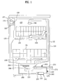
- FIG. 1 illustrates a sectional view of a dishwasher and controls, according to an embodiment of the invention
- FIG. 2 illustrates overall operation of a dishwasher, according to an embodiment of the invention.
- FIGS. 3 and 4 illustrate exemplary methods that may be employed to control the dishwasher of FIG. 1 , according to embodiments of the invention.
- FIG. 1 depicts a sectional view of a dishwasher and controls, according to an embodiment of the invention.
- the dishwasher can include a case 100, which defines an exterior appearance, a door 120 for opening and closing the case 100, and a control panel 130 mounted on the case 100 or door 120 for operating the dishwasher.
- the case 100 may include a washing compartment 150 having a tub 110. Dishes can be placed in the washing compartment 150.
- a sump 200 that may contain washing water can be positioned under the tub 110.
- a pump 210 and a filter (not shown) can be provided in the sump 200.
- the pump 210 can pump the washing water held in the sump 200.
- the filter can advantageously filter contaminated water.
- a sump heater 290 may be provided in the sump 200 to heat water inside the sump 200.
- a first water supply pipe 250 and a water drain pipe 270 can be connected with the sump 200.
- New clean water may be drawn from an external water source through the first water supply pipe 250 and the washing water inside the sump 200 can be drained outside through the water drain pipe 270.
- a first water supply valve 255 can be installed at the first water supply pipe 250 to control the supply of the water to the sump 200.
- At least one rack and spraying arm may be provided in the tub 110, such as inside the washing compartment 150, for example.
- the pump 210 pumps water and the spraying arm sprays the pumped water toward the rack.
- an upper rack 160 and a lower rack 170 can be disposed in an upper portion and a lower portion of the washing compartment 150, respectively.
- an upper spraying arm 230 and a lower spraying arm 220 can then be placed near the upper rack 160 and the lower rack 170 to spray the water pumped by the pump 210 at each respective rack.
- Washing compartment 150 may also include a top nozzle 240 in its upper portion to spray the water pumped by the pump 210 downward.
- Dishwasher may include a steam generator 300 to supply steam to the washing compartment 150.
- Washing water may be circulated in the washing compartment 150 using the pump 210, and, for example, the lower spraying arm 220 and/or upper spraying arm 230.
- steam generator 300 can be operated separately from the sump heater 290.
- the steam generator 300 may be in communication with the first water supply pipe 250.
- the steam generator 300 may be in communication with the washing compartment 150 via a steam supply pipe 280.
- a second water supply valve 265 may be installed at a second water supply pipe 260 to control the supply of the water to the steam generator 300.
- Steam generator 300 can include a steam heater 310 for heating the water supplied to the steam generator 300 and a water level sensor 320 for sensing a water level inside the steam generator 300.
- the water level sensor 320 may sense a low level and a high level of water, for example. The low level can be predetermined or set to protect the steam heater 310 of the steam generator 300 and the high level can be predetermined or set to prevent the water supplied to the steam generator 300 from overflowing.
- the steam generator 300 may include a steam supply valve (not shown) for controlling the opening and closing of the steam supply pipe 280 so that the steam can be supplied to the washing compartment 150 at various times or intervals.
- the sump 200 may include a pollution level sensor (not shown) in a predetermined portion of the sump 200, which measures a pollution level of the washing water circulated in the tub 110, for example.
- the door 120 may include an exhaust fan 190 and an exhaust duct 192 to exhaust damp air from the washing compartment 150.
- a control unit 102 which controls the dishwasher, may be operationally connected with the control panel 130, the pump 210, and the steam generator 300.
- the controller 102 may control the dishwasher in accordance with predetermined instructions stored in a memory (not shown).
- the controller 102 may be operationally coupled with at least the control panel 130, the washing pump 210, and the steam generator 300 so that they may be operated in accordance with a user's selection on the control panel 130.
- an operational mode of the dishwasher may be determined based on a user's selection or a type of a dish.
- the operational mode may be determined based on a pollution or contamination level of a dish.
- operating parameters such as the number of rotations per minute of the motor or the amount of detergent can be selected based on the determined operational mode.
- the method of controlling or operating the dishwasher may include performing a washing cycle (W), rinsing (R) cycle, and drying cycle.
- W washing cycle
- R rinsing
- drying cycle the moisture remaining on the dishes can be removed.
- smaller cycles may be performed within each of the washing, rinsing, or drying cycles and/or other cycles may be included.
- the dishwasher can include a washing compartment 150 having at least one rack to hold dishes, such as upper rack 160 and lower rack 170, a sump 200, which may be configured to contain water, and a steam generator 300.
- dishwasher can preheat the steam generator 300 at substantially the same time as performing a washing cycle (W) for a preset time period, draining water, and/or supplying new water, or using one or more spraying arms 220 and 230 to spray water to at least one rack 160 and 170.
- W washing cycle
- Dishwasher may increase a temperature of used and unused dishes to improve its efficiency and speed.
- food scraps on the dishes can also be soaked with water or steam, and germs or bacteria on the dishes may be removed.
- water heated by the sump heater 290 can be sprayed at dishes placed in the washing compartment 150.
- steam generated by the steam generator 300 can be supplied to the washing compartment 150.
- the use of steam can provide a more efficient use of energy than spraying water that is heated by the sump heater 290. This can occur because the energy consumed by the sump heater 290 to heat the water may be larger than the energy consumed by the steam generator 300 to generate steam.
- the use of steam during various cycles of the dishwasher, such as a washing (W) or rinsing (R) cycle can economize the amount of energy and water needed to operate the dishwasher.
- a heater inside the steam generator 300 can preheat the steam generator 300 and/or water used to generate steam over the boiling temperature for a predetermined period of time to generate steam faster. This can be advantageous because steam may not be generated at the moment the steam generator 300 is switched into an on state to generate steam.
- the dishwasher when steam is not sprayed substantially simultaneously with the start of the washing cycle (W), the dishwasher can use the spraying arms 220 and 230 to spray water and at substantially the same time it operates the sump heater 290 to heat the water at a gradual or expedited pace.
- the washing water used in the washing cycle (W) can be drained. New water may then be supplied for the rinsing cycle (R).
- steam can be generated or supplied to the washing compartment 150 and newly supplied water may be sprayed in the washing compartment 150.
- the steam generator 300 can be preheated for a predetermined time period so that steam can be sprayed substantially simultaneously with the start of the rinsing cycle (R).
- the predetermined time period can be two to four minutes.
- an electric current can be applied to an electric heater 310 provided in the steam generator 300 to preheat it.
- the rinse cycle (R) can be performed right after the wash cycle (W) is complete. It may be advantageous to allow preheating of the steam generator 300 for a predetermined time period substantially simultaneously with the performance of the washing cycle (W) when this occurs.
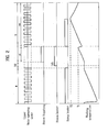
- FIG. 2 illustrates overall operation of the dishwasher, according to an embodiment of the invention, including exemplary methods employed to control the operation of the dishwasher.
- the exemplary methods include performing a preliminary wash cycle (P), a main washing cycle (W), and a rinsing cycle (R).
- P preliminary wash cycle
- W main washing cycle
- R rinsing cycle
- the exemplary methods can be used to control a dishwasher so unused dishes having a substantially smaller washing load than used dishes (having foreign matter from food or drink) can be washed faster and more efficiently with respect to time and energy, for example.
- the exemplary methods can include a washing cycle (W) and a rinsing cycle (R).
- W washing cycle
- R rinsing cycle
- the sump heater 290 can be operated after the washing water is supplied to the washing compartment 150.
- the supplying of the water during the washing cycle (W) may include spraying water using the upper spraying arm 230 and/or the lower spraying arm 220.
- the spraying of water by the upper 230 and lower 220 spraying arms can be alternately repeated for a predetermined time period (hereinafter, "alternate upper and lower spraying").
- the alternate upper and lower spraying may be repeated alternately or sequentially for one or more predetermined time periods.
- the water used during the washing cycle can be supplied from an external water source.
- An external water source may include a city or household water system connected to first water supply pipe 250, and may also include the sump 200.
- the supplied water may be cold, room temperature, or heated to a predetermined temperature to reduce the washing time.
- water temperature may be denoted as (Tw).
- Tw water temperature
- the temperature of the water supplied can be between approximately 40°C and 50°C.
- the water supplied can be heat-exchanged with the sump 200, when this occurs the temperature of the supplied water may decrease and/or approach approximately 30°C.
- the sump heater 290 may be operated.
- the sump heater 290 can be turned on for a predetermined time period.
- the washing cycle (W) may be preset to be performed for a preset time period and may continue until the temperature of the water contained in the sump 200 reaches a preset temperature.
- the washing water used in the washing cycle (W) can be drained and water can be newly supplied (DS).
- the newly supplied water may be cold, warm, or heated. Because the temperature of the sump 200 may have increased from the sump heater 290 being turned on during the washing cycle (W), the newly supplied water may not drop in temperature drastically as can occur during the washing cycle (W).
- the electric heater 310 of steam generator 300 can be preheated during the draining of the washing water and the supplying of the new water (DS).
- Preheating steam generator 300 can advantageously allow steam to be supplied and sprayed during rinse cycle (R) after (or immediately after) the draining of the washing water and the supplying of new water (DS).
- steam can be sprayed in a primary period of the rinsing cycle (R) to enhance washing efficiency. Soaking and washing dishes using steam enables new dishes and old (unused) dishes with substantially smaller washing loads to be washed quickly and efficiently.
- the supplying of steam (st) and spraying of water (ws) can be performed sequentially.
- the temperature of the washing compartment 150 and the temperature of the sump 200 may be increased by the steam sprayed during the supplying of the steam (st) stages.
- the supplying of the steam (st) may be performed for a predetermined time period, or until the temperature of the washing compartment 150 or the sump 200 reaches a preset temperature (T1).
- T1 a preset temperature
- the supplying of the steam (st) can occur for approximately 5 (five) or more minutes.
- the spraying of the water (ws) can start.
- the sump heater 290 may be turned on, as may occur during the washing cycle (W).
- the temperature of the water during the washing cycle (W) and the rinsing cycle (R) may increase gradually.
- the overall washing time can be reduced.
- the water used during the rinsing cycle (R) may be heated by the sump heater 290 up to a preset temperature (T2), which can be approximately 60°C.
- T2 a preset temperature
- preheating steam generator 300 during the draining of the water and the supplying of the new water (DS) (hereinafter “drained/supplied” or "DS") can be used to drained which has been used and new clean water may be supplied to the washing compartment 150 and/or sprayed.
- FIG. 3 illustrates an exemplary method which may be employed to control a dishwasher according to an embodiment of the invention.
- the supplying of the steam (st) can occur before the spraying of the water (ws) during the rinsing cycle (R), and can overlap with the overall draining of the water and the supplying of the new water cycle (DS).
- the overall washing time can be reduced when the supplying of the steam (st) starts at substantially the same time as the draining of the water and the supplying of the new water (DS).
- the steam generator 300 can be preheated during the washing cycle (W) and the steam can be supplied to the washing compartment 150 from the steam generator 300 at approximately the same time as the draining of the water and the supplying of the new water (DS).
- the sump heater 290 can be turned on during the spraying of the washing water (ws) to improve efficiency and/or reducing washing time.
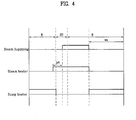
- FIG. 4 illustrates an exemplary method that may be employed to control a dishwasher.
- the supplying of the steam (st) can occur before the spraying of the water (ws) during the rinsing cycle (R) and can overlap a portion, such as a preset period, of the draining of the water and the supplying of the new water cycle (DS).
- the steam can be preheated during the washing cycle (W) and supplied to the washing compartment 150 before the draining of the water and the supplying of the new water (DS) is complete.
- operating the steam heater 310 of the steam generator 300 and the sump heater 290 substantially simultaneously during the washing cycle (W) can be inefficient and place a heavy load on the dishwasher.
- the preheating of the steam heater 310 can start just before the washing cycle (W) is complete, and the steam can then be supplied (st) to the washing compartment 150 in the middle of the draining of the water and the supplying of the new water cycle (DS).
- This configuration can reduce electrical overload, or reduce the amount of power drawn by the dishwasher and increase its efficiency, when operating the steam generator 300 and the sump heater 290.
- the steam can begin to be supplied (st) to the washing compartment 150 after or shortly after the washing cycle (W) completes.
- steam can be supplied (st) before or shortly before the draining of the water and the supplying of the new water (DS) completes.
- the preheating of the steam generator 300 using the steam heater 310 can start in the middle of the washing cycle (W).
- the supplying of the steam (st) can start at substantially the same time as the draining of the water and the supplying of the new water cycle (DS) and/or or before (DS) completes.
- Preheating of the steam generator 300 can overlap with the time that upper spraying arm 230 and lower spraying arm 220 spray water, which may be heated by the sump heater 290, in an alternating manner.
- the supplying of the steam (st) using the steam generator 300 may then overlap with the time that the spraying of the water (ws) in the washing cycle (W) occurs and/or before the draining of the water and the supplying of the new water cycle (DS) occurs.
- the steam generator 300 and the sump heater 290 can then be operated substantially simultaneously or partially overlap for a preset time period.
- the sump heater 290 may be turned on continuously.
- the sump heater 290 can also be turned off during the supplying of the steam (st) to the washing compartment 150 using the steam generator 300.
- the water draining and the new water supplying cycle (DS) cycle may occur for a substantially short period of the overall operation of the dishwasher.
- the preheating of the steam generator 300 overlaps with the time that the water draining and the new water supplying (DS) cycle starts, the overall washing time and efficiency can be improved.
- the supplying of the steam (st) starts at the beginning, middle, during, or after the water draining and the new water supplying of the (DS) cycle, the overall washing time and efficiency can be improved.
- the spraying of the rinsing water (ws) can start.
- the sump heater 290 can be turned on during the spraying of the rinsing water (ws) to improve efficiency.
- the time period to supply the steam (st) and the spray the water (ws) during the rinsing cycle (R) can be determined.
- the overall washing time can be determined.
Abstract
Description
- This application claims the benefit of Korean Patent Application No.
10-2008-0081796, filed on August 21, 2008 - The present disclosure generally relates to dishwashers. In particular, the present disclosure relates to controls for a dishwasher which improves washing efficiency and speed when used or dirty and new or clean dishes are washed together.
- A conventional dishwasher is a machine that sprays washing water on dishes placed in a tub to remove foreign matter, such as food scraps left on the dishes. Generally, the dishwasher is operated based on a washing cycle that sprays washing water mixed with detergent in a tub that contains dishes, in order to remove foreign matter left on the dishes. The dishwasher may also heat the washing water to improve performance. Typically, after the washing cycle, a rinsing cycle occurs which sprays washing water that is not mixed with the detergent in the tub to remove any remaining foreign matter. After the washing cycle, a drying cycle takes place, which dries the dishes.
- Typically, more than one spraying arm and at least one rack (for placing dishes, which need to be washed) are provided in a single tub of the conventional dishwasher. For example, a dishwasher usually has an upper rack and a lower rack in a bi-level configuration within the tub. A number of holders are then provided on the upper rack, which hold small dishes, such as small cups with a small washing load, and a smaller number of holders are provided on the lower rack, which hold large dishes, such as dinner dishes or large bowls with a larger washing load. An upper spraying arm and a lower spraying arm are then provided which spray washing water at the upper and lower racks, respectively.
- Often, users of a dishwasher desire to wash new dishes, which may be purchased recently and washed during the manufacturing process, as well as old dishes, which may be washed after a prior use. The reasons for rewashing new (referred to herein alternatively as "clean dishes" and "unused dishes") and old dishes (referred to herein alternatively as "dirty dishes" and "used dishes") can vary, but may include bacteria growth or dust collecting during storage or distribution. Typically, unused dishes include relatively little foreign matter compared to dishes used at meals and thus have substantially different washing loads. Unfortunately, the conventional dishwasher is not well-suited for washing unused dishes with used dishes. For example, it may be an inefficient use of time and energy to wash used dishes, which have a large washing load, with unused dishes, which have a small washing load in the same dishwasher (and in particular, the same washing compartment).
- The present disclosure is generally directed to a dishwasher that improves washing efficiency and methods of control and operation of the dishwasher. In some embodiments, used and unused dishes having varying washing loads can be washed in a single washing compartment of the dishwasher.
- Advantages and features of the invention in part may become apparent in the description which follows and in part may become apparent to those having ordinary skill in the art upon examination of the following or may be learned from practice of the embodiments described herein. The advantages and features of the embodiments of the present invention may be realized and attained by the structures and processes described in the written description, the claims, and in the appended drawings.
- To achieve these and other advantages and in accordance with the purpose of the present disclosure, as embodied and broadly described herein, a controlling method of a dishwasher including a washing compartment, a sump configured to contain water, a sump heater configured to heat the water, a steam generator, and at least one spraying arm is provided. The method may include performing a washing cycle by spraying water toward a rack provided in the washing compartment by using the spraying arm; draining water contained in the sump after being used in the washing cycle and supplying new water to the sump; preheating the steam generator during the draining, supplying, or draining and supplying; and rinsing including spraying steam to the washing compartment and spraying water by using the spraying arm, the spraying of the steam and the spraying of the water being performed sequentially.
- In exemplary embodiments, the sump heater may be turned on in the performing of the washing cycle and the rinsing. In addition, the sump heater may be turned on for the temperature of the sump heater to be over a preset first temperature during the rinsing. The first temperature may be between 60°C and 64°C. The preheating of the steam generator may be performed simultaneously with at least one of draining water and supplying new water. The steam generator may be preheated for 2 to 4 minutes.
- In an embodiment, a controlling method of a dishwasher including a washing compartment, a sump configured to contain water, a sump heater configured to heat the water, a steam generator, and at least one spraying arm may be provided. The controlling method may include performing a washing cycle by spraying water to an upper rack and a lower rack provided in the washing compartment by using an upper spraying arm and a lower spraying arm, respectively. Having the sump heater in a turned on state during the washing cycle. Rinsing by spraying steam generated at the steam generator into the washing compartment continuously, after draining the water used in the washing cycle and supplying new water, and spraying water to the washing compartment by using the upper spraying arm and the lower spraying arm alternately; and drying dishes placed in the rack.
- In some embodiments, the steam generator may be preheated during the draining water contained in the sump and the supplying new water. A steam heater provided in the steam generator may be preheated for 2 to 4 minutes.
- In an embodiment, a dishwasher including a washing compartment, at least one rack to hold dishes, a sump configured to contain water, the sump including a sump heater configured to heat the washing water may be provided. The dishwasher may also include a steam generator preheated for a predetermined time period, where the preheating occurs simultaneously with at least one of performing a washing cycle, draining water, and supplying new water; and at least one spraying arm configured to spray water toward the rack.
- In an embodiment, the steam can be sprayed at the same time that the performing of the washing cycle is complete, if the steam generator is preheated at the same time that the performing of the washing cycle starts. The steam may also be sprayed at the same time that the draining water and the supplying water is complete if the steam generator is preheated at the same time that the performing of the washing cycle starts.
- In some embodiments, a controlling method of a dishwasher including a washing compartment, a sump configured to contain water, a sump heater configured to heat the washing water, a steam generator and at least one spraying arm may be provided. The controlling method may include performing a washing cycle, draining water and supplying new water, and rinsing. The controlling method may further include supplying steam to the washing compartment prior to the rinsing, where rinsing may comprise spraying water into the washing compartment.
- In some embodiments, the supplying steam can include a period overlapped (partially or fully) with the draining water. The supplying of the steam may also include a period overlapped with the supplying new water. In an embodiment, the supplying of the steam may be continuously performed after the performing of the washing cycle. The steam generator may be preheated for a preset time period before the supplying steam.
- According to embodiments of the present disclosure, washing efficiency of the dishwasher may be improved when dishes with different washing loads, such as used and unused dishes, are washed in a single washing compartment. Advantageously, the time taken to wash the dishes can be reduced. In addition, the energy and water consumption of the dishwasher can be reduced.
- It is to be understood that both the foregoing general description and the following detailed description are exemplary and explanatory and should not be construed as limiting the scope of the claims.
- The accompanying drawings are included to provide a further understanding of the disclosure, and are incorporated herein and constitute a part of this application. The drawings together with the description serve to explain exemplary embodiments of the present disclosure. In the drawings:
-
FIG. 1 illustrates a sectional view of a dishwasher and controls, according to an embodiment of the invention; -
FIG. 2 illustrates overall operation of a dishwasher, according to an embodiment of the invention; and -
FIGS. 3 and4 illustrate exemplary methods that may be employed to control the dishwasher ofFIG. 1 , according to embodiments of the invention. - Reference will now be made in detail to the specific embodiments of the present disclosure, examples of which are illustrated in the accompanying drawings. Wherever possible, the same reference numbers will be used throughout the drawings to refer to the same or like parts.
-
FIG. 1 depicts a sectional view of a dishwasher and controls, according to an embodiment of the invention. The dishwasher can include acase 100, which defines an exterior appearance, adoor 120 for opening and closing thecase 100, and acontrol panel 130 mounted on thecase 100 ordoor 120 for operating the dishwasher. Thecase 100 may include awashing compartment 150 having atub 110. Dishes can be placed in thewashing compartment 150. - In an embodiment, a
sump 200 that may contain washing water can be positioned under thetub 110. Apump 210 and a filter (not shown) can be provided in thesump 200. Thepump 210 can pump the washing water held in thesump 200. The filter can advantageously filter contaminated water. In addition, asump heater 290 may be provided in thesump 200 to heat water inside thesump 200. - With continued reference to
FIG. 1 , a firstwater supply pipe 250 and awater drain pipe 270 can be connected with thesump 200. New clean water may be drawn from an external water source through the firstwater supply pipe 250 and the washing water inside thesump 200 can be drained outside through thewater drain pipe 270. A firstwater supply valve 255 can be installed at the firstwater supply pipe 250 to control the supply of the water to thesump 200. - In some embodiments, at least one rack and spraying arm may be provided in the
tub 110, such as inside thewashing compartment 150, for example. When dishes are placed on the rack, thepump 210 pumps water and the spraying arm sprays the pumped water toward the rack. As shown, anupper rack 160 and alower rack 170 can be disposed in an upper portion and a lower portion of thewashing compartment 150, respectively. In addition, anupper spraying arm 230 and alower spraying arm 220 can then be placed near theupper rack 160 and thelower rack 170 to spray the water pumped by thepump 210 at each respective rack.Washing compartment 150 may also include atop nozzle 240 in its upper portion to spray the water pumped by thepump 210 downward. - Dishwasher may include a
steam generator 300 to supply steam to thewashing compartment 150. Washing water may be circulated in thewashing compartment 150 using thepump 210, and, for example, thelower spraying arm 220 and/orupper spraying arm 230. In some embodiments,steam generator 300 can be operated separately from thesump heater 290. As shown, thesteam generator 300 may be in communication with the firstwater supply pipe 250. Thesteam generator 300 may be in communication with thewashing compartment 150 via asteam supply pipe 280. A secondwater supply valve 265 may be installed at a secondwater supply pipe 260 to control the supply of the water to thesteam generator 300. -
Steam generator 300 can include asteam heater 310 for heating the water supplied to thesteam generator 300 and awater level sensor 320 for sensing a water level inside thesteam generator 300. Thewater level sensor 320 may sense a low level and a high level of water, for example. The low level can be predetermined or set to protect thesteam heater 310 of thesteam generator 300 and the high level can be predetermined or set to prevent the water supplied to thesteam generator 300 from overflowing. In addition, thesteam generator 300 may include a steam supply valve (not shown) for controlling the opening and closing of thesteam supply pipe 280 so that the steam can be supplied to thewashing compartment 150 at various times or intervals. - The
sump 200 may include a pollution level sensor (not shown) in a predetermined portion of thesump 200, which measures a pollution level of the washing water circulated in thetub 110, for example. In an embodiment, thedoor 120 may include anexhaust fan 190 and anexhaust duct 192 to exhaust damp air from thewashing compartment 150. In some embodiments, acontrol unit 102, which controls the dishwasher, may be operationally connected with thecontrol panel 130, thepump 210, and thesteam generator 300. - The
controller 102 may control the dishwasher in accordance with predetermined instructions stored in a memory (not shown). Thecontroller 102 may be operationally coupled with at least thecontrol panel 130, thewashing pump 210, and thesteam generator 300 so that they may be operated in accordance with a user's selection on thecontrol panel 130. - A variety of operational modes may be predetermined in the dishwasher. For example, an operational mode of the dishwasher may be determined based on a user's selection or a type of a dish. In addition, the operational mode may be determined based on a pollution or contamination level of a dish. Advantageously, when the operational mode(s) is determined, operating parameters, such as the number of rotations per minute of the motor or the amount of detergent can be selected based on the determined operational mode.
- The method of controlling or operating the dishwasher may include performing a washing cycle (W), rinsing (R) cycle, and drying cycle. During the washing cycle (W), food scraps on the dishes can be removed. During the rinsing cycle (R), the dishes are rinsed. The rinsing cycle (R) may occur after the washing cycle (W). During the drying cycle, the moisture remaining on the dishes can be removed. In addition, smaller cycles may be performed within each of the washing, rinsing, or drying cycles and/or other cycles may be included.
- The dishwasher can include a
washing compartment 150 having at least one rack to hold dishes, such asupper rack 160 andlower rack 170, asump 200, which may be configured to contain water, and asteam generator 300. In an embodiment, dishwasher can preheat thesteam generator 300 at substantially the same time as performing a washing cycle (W) for a preset time period, draining water, and/or supplying new water, or using one or more sprayingarms rack - Dishwasher may increase a temperature of used and unused dishes to improve its efficiency and speed. When the temperature of the dishes is increased, food scraps on the dishes can also be soaked with water or steam, and germs or bacteria on the dishes may be removed. In an embodiment, during the washing cycle (W) water heated by the
sump heater 290 can be sprayed at dishes placed in thewashing compartment 150. In addition, steam generated by thesteam generator 300 can be supplied to thewashing compartment 150. - Of note, the use of steam can provide a more efficient use of energy than spraying water that is heated by the
sump heater 290. This can occur because the energy consumed by thesump heater 290 to heat the water may be larger than the energy consumed by thesteam generator 300 to generate steam. The use of steam during various cycles of the dishwasher, such as a washing (W) or rinsing (R) cycle can economize the amount of energy and water needed to operate the dishwasher. - In some embodiments, a heater inside the
steam generator 300 can preheat thesteam generator 300 and/or water used to generate steam over the boiling temperature for a predetermined period of time to generate steam faster. This can be advantageous because steam may not be generated at the moment thesteam generator 300 is switched into an on state to generate steam. In an embodiment, when steam is not sprayed substantially simultaneously with the start of the washing cycle (W), the dishwasher can use the sprayingarms sump heater 290 to heat the water at a gradual or expedited pace. - After the washing cycle (W) is complete, the washing water used in the washing cycle (W) can be drained. New water may then be supplied for the rinsing cycle (R). During the rinse cycle (R), steam can be generated or supplied to the
washing compartment 150 and newly supplied water may be sprayed in thewashing compartment 150. For example, thesteam generator 300 can be preheated for a predetermined time period so that steam can be sprayed substantially simultaneously with the start of the rinsing cycle (R). In an embodiment, the predetermined time period can be two to four minutes. In exemplary embodiments, an electric current can be applied to anelectric heater 310 provided in thesteam generator 300 to preheat it. - Of note, the rinse cycle (R) can be performed right after the wash cycle (W) is complete. It may be advantageous to allow preheating of the
steam generator 300 for a predetermined time period substantially simultaneously with the performance of the washing cycle (W) when this occurs. -
FIG. 2 illustrates overall operation of the dishwasher, according to an embodiment of the invention, including exemplary methods employed to control the operation of the dishwasher. Generally, the exemplary methods include performing a preliminary wash cycle (P), a main washing cycle (W), and a rinsing cycle (R). The exemplary methods can be used to control a dishwasher so unused dishes having a substantially smaller washing load than used dishes (having foreign matter from food or drink) can be washed faster and more efficiently with respect to time and energy, for example. - As shown, the exemplary methods can include a washing cycle (W) and a rinsing cycle (R). During the washing cycle (W), the
sump heater 290 can be operated after the washing water is supplied to thewashing compartment 150. The supplying of the water during the washing cycle (W) may include spraying water using theupper spraying arm 230 and/or thelower spraying arm 220. The spraying of water by the upper 230 and lower 220 spraying arms can be alternately repeated for a predetermined time period (hereinafter, "alternate upper and lower spraying"). For example, the alternate upper and lower spraying may be repeated alternately or sequentially for one or more predetermined time periods. - The water used during the washing cycle can be supplied from an external water source. An external water source may include a city or household water system connected to first
water supply pipe 250, and may also include thesump 200. The supplied water may be cold, room temperature, or heated to a predetermined temperature to reduce the washing time. InFIG. 2 , water temperature may be denoted as (Tw). For example, the temperature of the water supplied can be between approximately 40°C and 50°C. The water supplied can be heat-exchanged with thesump 200, when this occurs the temperature of the supplied water may decrease and/or approach approximately 30°C. - During the alternate upper and lower spraying of the washing cycle (W), the
sump heater 290 may be operated. For example, thesump heater 290 can be turned on for a predetermined time period. When thesump heater 290 is turned on, the washing cycle (W) may be preset to be performed for a preset time period and may continue until the temperature of the water contained in thesump 200 reaches a preset temperature. - When the washing cycle (W) is complete, the washing water used in the washing cycle (W) can be drained and water can be newly supplied (DS). The newly supplied water may be cold, warm, or heated. Because the temperature of the
sump 200 may have increased from thesump heater 290 being turned on during the washing cycle (W), the newly supplied water may not drop in temperature drastically as can occur during the washing cycle (W). - In an embodiment, the
electric heater 310 ofsteam generator 300 can be preheated during the draining of the washing water and the supplying of the new water (DS).Preheating steam generator 300 can advantageously allow steam to be supplied and sprayed during rinse cycle (R) after (or immediately after) the draining of the washing water and the supplying of new water (DS). For example, steam can be sprayed in a primary period of the rinsing cycle (R) to enhance washing efficiency. Soaking and washing dishes using steam enables new dishes and old (unused) dishes with substantially smaller washing loads to be washed quickly and efficiently. - With continued reference to
FIG. 2 , during the rinsing cycle (R) the supplying of steam (st) and spraying of water (ws) can be performed sequentially. Of note, the temperature of thewashing compartment 150 and the temperature of thesump 200 may be increased by the steam sprayed during the supplying of the steam (st) stages. The supplying of the steam (st) may be performed for a predetermined time period, or until the temperature of thewashing compartment 150 or thesump 200 reaches a preset temperature (T1). For example, the supplying of the steam (st) can occur for approximately 5 (five) or more minutes. When the supplying of the steam (st) is complete, the spraying of the water (ws) can start. During the spraying of the water (ws) in the rinsing cycle (R), thesump heater 290 may be turned on, as may occur during the washing cycle (W). - In some embodiments, the temperature of the water during the washing cycle (W) and the rinsing cycle (R) may increase gradually. When the temperature of the washing water or rinsing water increases, the overall washing time can be reduced. For example, the water used during the rinsing cycle (R) may be heated by the
sump heater 290 up to a preset temperature (T2), which can be approximately 60°C. Of note, preheatingsteam generator 300 during the draining of the water and the supplying of the new water (DS) (hereinafter "drained/supplied" or "DS") can be used to drained which has been used and new clean water may be supplied to thewashing compartment 150 and/or sprayed. -
FIG. 3 illustrates an exemplary method which may be employed to control a dishwasher according to an embodiment of the invention. As shown, the supplying of the steam (st), can occur before the spraying of the water (ws) during the rinsing cycle (R), and can overlap with the overall draining of the water and the supplying of the new water cycle (DS). Of note, the overall washing time can be reduced when the supplying of the steam (st) starts at substantially the same time as the draining of the water and the supplying of the new water (DS). In an embodiment, thesteam generator 300 can be preheated during the washing cycle (W) and the steam can be supplied to thewashing compartment 150 from thesteam generator 300 at approximately the same time as the draining of the water and the supplying of the new water (DS). In addition, thesump heater 290 can be turned on during the spraying of the washing water (ws) to improve efficiency and/or reducing washing time. -
FIG. 4 illustrates an exemplary method that may be employed to control a dishwasher. As shown inFIG. 4 , the supplying of the steam (st), can occur before the spraying of the water (ws) during the rinsing cycle (R) and can overlap a portion, such as a preset period, of the draining of the water and the supplying of the new water cycle (DS). In an embodiment, the steam can be preheated during the washing cycle (W) and supplied to thewashing compartment 150 before the draining of the water and the supplying of the new water (DS) is complete. Of note, operating thesteam heater 310 of thesteam generator 300 and thesump heater 290 substantially simultaneously during the washing cycle (W) can be inefficient and place a heavy load on the dishwasher. As shown, the preheating of thesteam heater 310 can start just before the washing cycle (W) is complete, and the steam can then be supplied (st) to thewashing compartment 150 in the middle of the draining of the water and the supplying of the new water cycle (DS). This configuration can reduce electrical overload, or reduce the amount of power drawn by the dishwasher and increase its efficiency, when operating thesteam generator 300 and thesump heater 290. - In some embodiments, when the
sump heater 290 and thesteam generator 300 may be operated simultaneously, the steam can begin to be supplied (st) to thewashing compartment 150 after or shortly after the washing cycle (W) completes. In addition, steam can be supplied (st) before or shortly before the draining of the water and the supplying of the new water (DS) completes. - With continued reference to both
FIGS. 3 and4 , the preheating of thesteam generator 300 using thesteam heater 310 can start in the middle of the washing cycle (W). In addition, the supplying of the steam (st) can start at substantially the same time as the draining of the water and the supplying of the new water cycle (DS) and/or or before (DS) completes. These washing controls and modes of operating the dishwasher can advantageously allow improved washing performance, such as reduced washing time and enhance energy efficiency. - Preheating of the
steam generator 300 can overlap with the time thatupper spraying arm 230 andlower spraying arm 220 spray water, which may be heated by thesump heater 290, in an alternating manner. The supplying of the steam (st) using thesteam generator 300 may then overlap with the time that the spraying of the water (ws) in the washing cycle (W) occurs and/or before the draining of the water and the supplying of the new water cycle (DS) occurs. Thesteam generator 300 and thesump heater 290 can then be operated substantially simultaneously or partially overlap for a preset time period. - In an embodiment, after the spraying of the water (ws) in the washing cycle (W) is complete, the
sump heater 290 may be turned on continuously. Thesump heater 290 can also be turned off during the supplying of the steam (st) to thewashing compartment 150 using thesteam generator 300. - The water draining and the new water supplying cycle (DS) cycle may occur for a substantially short period of the overall operation of the dishwasher. In some embodiments, when the preheating of the
steam generator 300 overlaps with the time that the water draining and the new water supplying (DS) cycle starts, the overall washing time and efficiency can be improved. In some embodiments, when the supplying of the steam (st) starts at the beginning, middle, during, or after the water draining and the new water supplying of the (DS) cycle, the overall washing time and efficiency can be improved. - When the supplying of the steam (st) completes, the spraying of the rinsing water (ws) can start. Of note, the
sump heater 290 can be turned on during the spraying of the rinsing water (ws) to improve efficiency. When the supplying of the steam (st) and the spraying of the water (ws) occur for respective preset time periods during the washing cycle (W), the time period to supply the steam (st) and the spray the water (ws) during the rinsing cycle (R) can be determined. Thus, the overall washing time can be determined. - It will be apparent to those skilled in the art that various modifications and variations can be made in the present disclosure without departing from the spirit or scope of the disclosure. Thus, it is intended that the present disclosure cover any modifications and variations within the scope of the appended claims and their equivalents.
Claims (15)
- A controlling method of a dishwasher comprising a washing compartment, a sump configured to contain water, a sump heater configured to heat the water, a steam generator and at least one spraying arm, the method comprising:performing a washing cycle by spraying water toward a rack provided in the washing compartment by using the spraying arm;draining water contained in the sump after being used in the washing cycle and supplying new water to the sump;preheating the steam generator during the draining and supplying; andrinsing by spraying steam into the washing compartment and spraying water by using the spraying arm, the spraying steam and the spraying water being performed sequentially.
- The controlling method of claim 1, wherein the sump heater is turned on for at least a portion of the time during performing of the washing cycle and rinsing.
- The controlling method of claim 1, wherein the sump heater is turned on to maintain water in the sump over a preset first temperature during at least a portion of the rinsing.
- The controlling method of claim 3, wherein the first temperature is between 60°C and 64°C.
- The controlling method of claim 1, wherein the preheating of the steam generator is performed simultaneously with at least one of the draining water and the supplying new water.
- The controlling method of claim 5, wherein the steam generator is preheated for 2 to 4 minutes.
- A controlling method of a dishwasher comprising a washing compartment, a sump configured to contain water, a sump heater configured to heat the water, a steam generator, and at least one spraying arm, the controlling method comprising:performing a washing cycle while the sump heater is turned on, by spraying water toward an upper rack and a lower rack provided in the washing compartment by using an upper spraying arm and a lower spraying arm, respectively;rinsing by:spraying steam generated by the steam generator into the washing compartment continuously, after draining the water used in the washing cycle,supplying new water to the sump, andspraying water into the washing compartment by using the upper spraying arm and the lower spraying arm alternately; anddrying dishes placed in the upper and lower racks.
- The controlling method of claim 7, wherein the steam generator is preheated during the draining of the water contained in the sump and the supplying of new water.
- The controlling method of claim 8, wherein a steam heater provided in the steam generator is preheated for 2 to 4 minutes.
- A dishwasher comprising:a washing compartment comprising at least one rack to hold dishes;a sump configured to contain water, the sump comprising a sump heater configured to heat the water;a steam generator configured to be preheated for a predetermined time period, simultaneously with at least one of performing a washing cycle, draining water from the sump, and supplying new water to the sump; andat least one spraying arm configured to spray water toward the rack.
- The controlling method of claim 10, wherein the steam is sprayed at the same time that the performing of the washing cycle is complete, if the steam generator is preheated at the same time that the performing of the washing cycle starts.
- A controlling method of a dishwasher comprising a washing compartment, a sump configured to contain water, a sump heater configured to heat the water, a steam generator, and at least one spraying arm, the controlling method comprising:performing a washing cycle,draining water from the sump;supplying new water to the sump;supplying steam to the washing compartment; andrinsing a contents of the washing compartment,wherein supplying steam to the washing compartment begins before rinsing.
- The controlling method of claim 12, wherein the supplying steam includes a period overlapped with draining water.
- The controlling method of claim 12, wherein the supplying steam is continuously performed after the performing of the washing cycle.
- The controlling method of claim 12, wherein the steam generator is preheated for a preset time period before the supplying steam.
Applications Claiming Priority (1)
| Application Number | Priority Date | Filing Date | Title |
|---|---|---|---|
| KR1020080081796A KR20100023169A (en) | 2008-08-21 | 2008-08-21 | Dishwasher and controlling method for the same |
Publications (2)
| Publication Number | Publication Date |
|---|---|
| EP2156780A2 true EP2156780A2 (en) | 2010-02-24 |
| EP2156780A3 EP2156780A3 (en) | 2016-10-12 |
Family
ID=41323627
Family Applications (1)
| Application Number | Title | Priority Date | Filing Date |
|---|---|---|---|
| EP09010550.3A Withdrawn EP2156780A3 (en) | 2008-08-21 | 2009-08-17 | Dishwasher and controlling method of the same |
Country Status (4)
| Country | Link |
|---|---|
| US (1) | US20100043827A1 (en) |
| EP (1) | EP2156780A3 (en) |
| KR (1) | KR20100023169A (en) |
| CN (1) | CN101653351B (en) |
Families Citing this family (2)
| Publication number | Priority date | Publication date | Assignee | Title |
|---|---|---|---|---|
| CN109730603B (en) * | 2019-01-16 | 2020-11-06 | 佛山市云米电器科技有限公司 | Dish washing machine and control method thereof |
| CN110279373B (en) * | 2019-06-18 | 2021-12-17 | 佛山市顺德区美的洗涤电器制造有限公司 | Control method of washing electric appliance, washing electric appliance and storage medium |
Family Cites Families (15)
| Publication number | Priority date | Publication date | Assignee | Title |
|---|---|---|---|---|
| NL271783A (en) * | 1961-01-30 | |||
| US3918644A (en) * | 1974-11-05 | 1975-11-11 | Whirlpool Co | Invertible dual action spray arm for dishwasher |
| US4457323A (en) * | 1979-02-02 | 1984-07-03 | Norris Industries | Dishwasher with steam generating heater and cold water input |
| ES2267511T3 (en) * | 2000-03-30 | 2007-03-16 | Imetec S.P.A. | DOMESTIC APPARATUS FOR STEAM GENERATION. |
| DE10164503A1 (en) * | 2001-12-28 | 2003-07-17 | Bsh Bosch Siemens Hausgeraete | Dishwasher for holding items to be cleaned arranged in a washing container |
| US20050241675A1 (en) * | 2004-05-03 | 2005-11-03 | Jung Moon K | Water guide for dishwasher and dishwasher having the same |
| KR100816906B1 (en) * | 2005-05-31 | 2008-03-26 | 엘지전자 주식회사 | Dish washer controlling method for the same |
| JP2006345928A (en) * | 2005-06-13 | 2006-12-28 | Toshiba Corp | Dishwasher |
| KR101052779B1 (en) * | 2006-04-07 | 2011-07-29 | 삼성전자주식회사 | Dishwashers and dishwashing methods that can be steamed |
| KR101283745B1 (en) * | 2006-06-19 | 2013-07-08 | 엘지전자 주식회사 | Dish washer |
| EP1738677B1 (en) * | 2006-06-23 | 2008-08-06 | V-Zug AG | Dishwasher with steam generator and method of its operation |
| CN101161180A (en) * | 2006-10-13 | 2008-04-16 | 乐金电子(天津)电器有限公司 | Dish washing machine and controlling method of dish washing machine |
| KR20080034549A (en) * | 2006-10-17 | 2008-04-22 | 엘지전자 주식회사 | Controlling method of dish washer |
| US8555676B2 (en) * | 2007-08-31 | 2013-10-15 | Whirlpool Corporation | Fabric treatment appliance with steam backflow device |
| DE102007053381B3 (en) * | 2007-11-09 | 2009-04-02 | Meiko Maschinenbau Gmbh & Co.Kg | Dishwasher with latent heat storage |
-
2008
- 2008-08-21 KR KR1020080081796A patent/KR20100023169A/en not_active Application Discontinuation
-
2009
- 2009-08-17 EP EP09010550.3A patent/EP2156780A3/en not_active Withdrawn
- 2009-08-20 CN CN200910170403XA patent/CN101653351B/en not_active Expired - Fee Related
- 2009-08-20 US US12/461,680 patent/US20100043827A1/en not_active Abandoned
Also Published As
| Publication number | Publication date |
|---|---|
| CN101653351B (en) | 2011-08-03 |
| KR20100023169A (en) | 2010-03-04 |
| CN101653351A (en) | 2010-02-24 |
| EP2156780A3 (en) | 2016-10-12 |
| US20100043827A1 (en) | 2010-02-25 |
Similar Documents
| Publication | Publication Date | Title |
|---|---|---|
| US9060668B2 (en) | Controlling method of dishwasher | |
| EP2156776B1 (en) | Dishwasher and controlling method of the same | |
| US20080289654A1 (en) | Dish washing machine and control method of the same | |
| EP2156774B1 (en) | Controlling method of dishwasher | |
| CN211066474U (en) | Dish washing machine | |
| EP2156775B1 (en) | Control method for a dishwasher | |
| US9271626B2 (en) | Steam activation or deactivation of chemistry in an appliance | |
| RU2500336C2 (en) | Dishwasher | |
| US20080236622A1 (en) | Control method of dish washing machine | |
| US20110083699A1 (en) | Method for operating a water-conducting domestic appliance | |
| US20090056763A1 (en) | Dish washing machine | |
| EP2156780A2 (en) | Dishwasher and controlling method of the same | |
| KR20110046181A (en) | Dish washer and controll method thereof | |
| US20100212697A1 (en) | Controlling method of a dishwasher | |
| EP2133019B1 (en) | Method for shortened clear rinse in a dishwasher and dishwasher adapted to carry out such method | |
| US20120118323A1 (en) | Method to remove fatty soils in a dishwasher | |
| JPH11206687A (en) | Kitchen cabinet with built-in tableware washing-drying machine | |
| JPH06327602A (en) | Dishwasher | |
| JPS6021733A (en) | Tablewear washer |
Legal Events
| Date | Code | Title | Description |
|---|---|---|---|
| PUAI | Public reference made under article 153(3) epc to a published international application that has entered the european phase |
Free format text: ORIGINAL CODE: 0009012 |
|
| AK | Designated contracting states |
Kind code of ref document: A2 Designated state(s): AT BE BG CH CY CZ DE DK EE ES FI FR GB GR HR HU IE IS IT LI LT LU LV MC MK MT NL NO PL PT RO SE SI SK SM TR |
|
| AX | Request for extension of the european patent |
Extension state: AL BA RS |
|
| 17P | Request for examination filed |
Effective date: 20140331 |
|
| RBV | Designated contracting states (corrected) |
Designated state(s): AT BE BG CH CY CZ DE DK EE ES FI FR GB GR HR HU IE IS IT LI LT LU LV MC MK MT NL NO PL PT RO SE SI SK SM TR |
|
| PUAL | Search report despatched |
Free format text: ORIGINAL CODE: 0009013 |
|
| AK | Designated contracting states |
Kind code of ref document: A3 Designated state(s): AT BE BG CH CY CZ DE DK EE ES FI FR GB GR HR HU IE IS IT LI LT LU LV MC MK MT NL NO PL PT RO SE SI SK SM TR |
|
| AX | Request for extension of the european patent |
Extension state: AL BA RS |
|
| RIC1 | Information provided on ipc code assigned before grant |
Ipc: A47L 15/42 20060101ALI20160908BHEP Ipc: A47L 15/00 20060101ALI20160908BHEP Ipc: A47L 15/46 20060101AFI20160908BHEP |
|
| STAA | Information on the status of an ep patent application or granted ep patent |
Free format text: STATUS: REQUEST FOR EXAMINATION WAS MADE |
|
| STAA | Information on the status of an ep patent application or granted ep patent |
Free format text: STATUS: THE APPLICATION IS DEEMED TO BE WITHDRAWN |
|
| 18D | Application deemed to be withdrawn |
Effective date: 20170413 |