EP2155972B1 - Power machine or vehicle with power management - Google Patents
Power machine or vehicle with power management Download PDFInfo
- Publication number
- EP2155972B1 EP2155972B1 EP08742519.5A EP08742519A EP2155972B1 EP 2155972 B1 EP2155972 B1 EP 2155972B1 EP 08742519 A EP08742519 A EP 08742519A EP 2155972 B1 EP2155972 B1 EP 2155972B1
- Authority
- EP
- European Patent Office
- Prior art keywords
- control
- engine speed
- power management
- feedback
- engine
- Prior art date
- Legal status (The legal status is an assumption and is not a legal conclusion. Google has not performed a legal analysis and makes no representation as to the accuracy of the status listed.)
- Active
Links
Images




Classifications
-
- F—MECHANICAL ENGINEERING; LIGHTING; HEATING; WEAPONS; BLASTING
- F16—ENGINEERING ELEMENTS AND UNITS; GENERAL MEASURES FOR PRODUCING AND MAINTAINING EFFECTIVE FUNCTIONING OF MACHINES OR INSTALLATIONS; THERMAL INSULATION IN GENERAL
- F16H—GEARING
- F16H61/00—Control functions within control units of change-speed- or reversing-gearings for conveying rotary motion ; Control of exclusively fluid gearing, friction gearing, gearings with endless flexible members or other particular types of gearing
- F16H61/38—Control of exclusively fluid gearing
- F16H61/40—Control of exclusively fluid gearing hydrostatic
- F16H61/46—Automatic regulation in accordance with output requirements
- F16H61/475—Automatic regulation in accordance with output requirements for achieving a target power, e.g. input power or output power
-
- E—FIXED CONSTRUCTIONS
- E02—HYDRAULIC ENGINEERING; FOUNDATIONS; SOIL SHIFTING
- E02F—DREDGING; SOIL-SHIFTING
- E02F9/00—Component parts of dredgers or soil-shifting machines, not restricted to one of the kinds covered by groups E02F3/00 - E02F7/00
- E02F9/20—Drives; Control devices
- E02F9/22—Hydraulic or pneumatic drives
- E02F9/2246—Control of prime movers, e.g. depending on the hydraulic load of work tools
-
- E—FIXED CONSTRUCTIONS
- E02—HYDRAULIC ENGINEERING; FOUNDATIONS; SOIL SHIFTING
- E02F—DREDGING; SOIL-SHIFTING
- E02F9/00—Component parts of dredgers or soil-shifting machines, not restricted to one of the kinds covered by groups E02F3/00 - E02F7/00
- E02F9/20—Drives; Control devices
- E02F9/22—Hydraulic or pneumatic drives
- E02F9/2278—Hydraulic circuits
- E02F9/2296—Systems with a variable displacement pump
-
- F—MECHANICAL ENGINEERING; LIGHTING; HEATING; WEAPONS; BLASTING
- F16—ENGINEERING ELEMENTS AND UNITS; GENERAL MEASURES FOR PRODUCING AND MAINTAINING EFFECTIVE FUNCTIONING OF MACHINES OR INSTALLATIONS; THERMAL INSULATION IN GENERAL
- F16H—GEARING
- F16H61/00—Control functions within control units of change-speed- or reversing-gearings for conveying rotary motion ; Control of exclusively fluid gearing, friction gearing, gearings with endless flexible members or other particular types of gearing
- F16H61/38—Control of exclusively fluid gearing
- F16H61/40—Control of exclusively fluid gearing hydrostatic
- F16H61/42—Control of exclusively fluid gearing hydrostatic involving adjustment of a pump or motor with adjustable output or capacity
- F16H61/431—Pump capacity control by electro-hydraulic control means, e.g. using solenoid valves
-
- F—MECHANICAL ENGINEERING; LIGHTING; HEATING; WEAPONS; BLASTING
- F16—ENGINEERING ELEMENTS AND UNITS; GENERAL MEASURES FOR PRODUCING AND MAINTAINING EFFECTIVE FUNCTIONING OF MACHINES OR INSTALLATIONS; THERMAL INSULATION IN GENERAL
- F16H—GEARING
- F16H61/00—Control functions within control units of change-speed- or reversing-gearings for conveying rotary motion ; Control of exclusively fluid gearing, friction gearing, gearings with endless flexible members or other particular types of gearing
- F16H61/38—Control of exclusively fluid gearing
- F16H61/40—Control of exclusively fluid gearing hydrostatic
- F16H61/46—Automatic regulation in accordance with output requirements
- F16H61/465—Automatic regulation in accordance with output requirements for achieving a target input speed
-
- B—PERFORMING OPERATIONS; TRANSPORTING
- B60—VEHICLES IN GENERAL
- B60W—CONJOINT CONTROL OF VEHICLE SUB-UNITS OF DIFFERENT TYPE OR DIFFERENT FUNCTION; CONTROL SYSTEMS SPECIALLY ADAPTED FOR HYBRID VEHICLES; ROAD VEHICLE DRIVE CONTROL SYSTEMS FOR PURPOSES NOT RELATED TO THE CONTROL OF A PARTICULAR SUB-UNIT
- B60W30/00—Purposes of road vehicle drive control systems not related to the control of a particular sub-unit, e.g. of systems using conjoint control of vehicle sub-units
- B60W30/14—Adaptive cruise control
Definitions
- Power machines such as work vehicles, loaders or diggers include multiple hydraulic circuits that are used to drive, steer and power work functions of the machine or vehicle.
- a hydrostatic drive assembly including a hydrostatic drive pump which supplies fluid to a hydrostatic motor to operate or drive the work vehicle or machine.
- hydraulic cylinders are used to implement lift, tilt or other mechanical work functions. Fluid is supplied to the hydraulic cylinders via operation of additional work pumps.
- Each of the drive and additional work pumps are powered by the engine.
- the load on the engine can exceed power limits of the engine, causing the engine to stall.
- WO 2006/054711 relates to a control system for a hydraulic construction machine.
- a mode select command selects an economy mode
- a mode selecting section is turned on to output an engine speed correction value that is calculated by an engine speed correction value operating section. Further calculations are performed to obtain an engine speed which is reduced by mode selection to improve fuel consumption.
- a further control system is shown in US 6 644 429 B2 .
- the present invention is defined by the features of independent claim 1. Further preferred embodiments of the invention are defined in the dependent claims.
- the present invention relates to power management control for a power machine or vehicle.
- a user interface of the power machine or vehicle includes a power management selection for activating and deactivating power management control.
- Power management control is implemented through a power management control component based upon feedback from an RPM sensor.
- the power management control component utilizes control methods and characteristics stored in system memory to determine control input to adjust hydrostatic parameters for power management.
- FIG. 1 illustrates an embodiment of a power machine or vehicle 100 in which the present invention can be incorporated or used.
- the illustrated power machine includes a body 104 that is supported relative to a frame (not shown). Wheels 106 are coupled to the frame so that the power machine 100 or vehicle can be driven over the ground during use.
- Application, however, of the present invention is not limited to a wheeled vehicle or loader as shown.
- the present invention has application for a power machine, which moves along a track instead of wheels.
- the illustrated power machine 100 includes a lift arm assembly 110 that is used to raise, lower or position a work implement or attachment 112, (which in the illustrated embodiment is a bucket).
- the lift arm assembly 110 includes lift arms 120 (only one of which is shown in FIG. 1 ).
- Lift arms 120 are pivotally coupled to the body 104 of the machine to raise and lower the attachment 112.
- Hydraulic cylinders or actuators 124 (only one shown in FIG. 1 ) are coupled to the body 104 and lift arms 120 to raise and lower the lift arms 120.
- the lift arm assembly 110 is shown in the lowered position and shown in the raised position in phantom.
- the direction and speed of the vehicle is controlled through various operating controls on a user interface 130 (illustrated schematically) located in the cab or located remotely.
- the operating controls include joysticks, levers or pedals.
- the attachment or implement 112 is rotationally coupled to the lift arm assembly 110 so that an orientation of the implement 112 can be adjusted relative to the lift arm assembly 110.
- Implement 112 is rotationally adjusted or tilted via a tilt cylinder (not shown in FIG. 1 ).
- the tilt cylinder is extended and retracted to adjust the orientation or tilt (e.g. curl or dump position) of the attachment or implement 112.
- FIG. 1 illustrates a bucket attachment or implement
- application is not limited to a bucket and other implements can be attached to the lift arm assembly 110 or machine depending upon the particular work application.
- lift arm assembly 110 of the power machine can support a spade or other implement.
- vehicle 100 is driven by a hydrostatic drive assembly and work functions are operated hydraulically.
- the hydrostatic drive assembly includes one or more or drive pumps or pumps 202 and a hydrostatic drive motor or motors 204 (both illustrated schematically). Output torque from the drive motor or motors 204 is used to rotate wheels 106 of the power machine or vehicle through a drive transmission 205.
- the hydrostatic drive pump (or pumps) 202 is a variable displacement pump having a variable flow control component (not shown) or swashplate responsive to electronic control.
- the magnitude and direction of fluid flow from the pump 202 is controlled through the various operating controls of the user interface 130 to impart forward and reverse motion to the vehicle or power machine.
- the various operating controls of the user interface 130 are operably coupled to the flow control component of the pump 202 to adjust the magnitude and direction of fluid flow to control the direction and speed of the vehicle.
- the various hydraulic circuitry includes various hydraulic controls or circuitry 210 (illustrated schematically) that control fluid flow and direction to the lift cylinder 124 and tilt cylinders 211 (illustrated schematically) based on input from the operating controls of the user interface 130. Fluid is supplied to the hydraulic circuitry for lift and tilt functions via work pump 212. Additionally, in the illustrated embodiment, work pump 212 supplies fluid to auxiliary hydraulics 214 to operate auxiliary functions for more complex implements or attachments based upon input from the user interface 130.
- the hydrostatic drive pump(s) 202 and work pump(s) 212 are powered by engine 216.
- Speed e.g. RPMS "revolutions-per-minute"
- Excessive load on the engine can decrease output RPMs of the engine making it difficult for the engine to keep up with the power demand of the hydrostatic drive assembly and other hydraulic systems.
- Such excessive demand on the engine 216 via the hydrostatic drive assembly or other systems e.g. hydraulic controls and circuitry 210 or auxiliary hydraulics 214) can cause the engine 216 to stall.
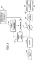
- FIG. 3 illustrates a power management system to control engine stall in response to excessive power demand
- the pump 202 is a variable displacement pump having a variable flow control component or swashplate (not shown) responsive to electronic control through controller 220.
- the controller 220 receives input from various operating controls of the user interface 130 to adjust or control the magnitude and direction of fluid flow from pump 202.
- the power management function shown includes a power management component 222 which receives engine RPMs feedback from a sensor 224 and provides a control input to the controller 220 to adjust pump stroke or displacement to control power usage based upon the feedback engine RPMs. As described, the power management component 220 receives feedback of the engine RPM to adjust pump displacement responsive to engine load or RPMs.
- engine RPMs decrease.
- the power management component 222 provides a control input to the controller 220 to adjust the flow control of the pump 202 to reduce the stroke or displacement of the pump 202 to manage power usage.
- the power management component 222 provides a control input so that the pump can operate at stroke commanded or selected by an operator through the operating controls of the user interface 130.
- pump stroke is automatically controlled based upon sensor feedback and operator input or commands from operating controls (e.g. joysticks) .
- operating controls e.g. joysticks
- users are more skilled at controlling operation of the machine and can control the machine directly without control input from the power management component or other feedback.
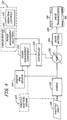
- FIG. 4 illustrates a control embodiment for a power machine where like numbers are used to refer to like parts in the previous FIGS.
- the user interface 130 includes operating controls 230 (e.g. including various levers, pedals or joysticks) and a power management selection 232 that allows the user to activate or deactivate power management control depending upon preference or experience.
- the power management selection 232 is active, the power management component 222 receives engine speed sensor feedback and provides control input to controller 220 to adjust pump stroke or displacement to control or manage power usage as previously described.
- the controller 220 adjusts displacement of pump 202 based upon operating control input without input from the power management component 222 or other feedback.
- the power management component 222 receives input from a throttle position sensor 233 to control power usage. Input from the throttle position sensor 233 and engine RPM sensor 224 provide an indication of demand engine speed verses actual engine speed for purposes of determining power demand and controlling power management.
- FIGS. 5-1 and 5-2 illustrate example embodiments of selectors of the user interface 130 for selecting or activating power management control.
- the selector includes a rotatable selector dial 240 having a plurality of indicia including "on” indicia for activating power management control and "off” indicia for no control.
- Dial 240 is rotatable as illustrated by arrow 244 between multiple positions including the "on" position (as indicated by “on” indicia) to enable power management and "off" position (as indicated by “off” indicia).
- the controller 220 does not use engine speed sensor feedback to control hydrostatic drive functions.
- the selector includes a selector switch or toggle 254 having an "on" position and an “off” position.
- power management is active and the controller 220 receives control input from the power management component 222 to manage power usage.
- power management component 222 does not modify control input based upon engine speed feedback as previously described.
- FIGS. 5-1 and 5-2 illustrate various selectors for power management selection, application is not limited to the particular embodiments shown and other selector devices can be used as will be appreciated by those skilled in the art.
- FIG. 6 schematically illustrates a control system including a plurality of control modes.
- the system includes power management control implemented through the power management component 222 and speed control implemented through a speed control component 260.
- the user interface 130 includes a power management selection 232, a speed control selection 262 and a no control selection 264.
- the power management selection activates power management control.
- the speed control selection 262 activates a speed control mode.
- the speed control component 260 receives feedback from the engine RPM sensor 224 and is configured to determine a control input to the controller 220 to maintain or control speed.
- the controller 220 uses the control input from the speed control component 260 to adjust or control pump displacement or stroke to maintain a set speed defined by user input via the operating controls 230.
- the controller Upon activation of the no control selection 264, the controller receives input from operating controls 230 but does not modify control input based upon feedback from sensors through the power management component 222 and/or speed control component 260.
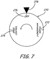
- FIG. 7 schematically illustrates an embodiment of a mode selector including a rotatable selector dial 270 for selecting power management control, speed control and no control.
- the rotatable selector dial 270 includes a plurality of indicia including power management control indicia 272, speed control indicia 274 and no control indicia 276 (e.g. "off").
- Selection dial 270 is rotated to align the indicia corresponding to the desired control mode with a selector mark 278 or other indicia.
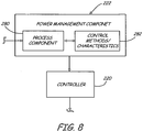
- the power management component 222 is configured to receive feedback from sensors 224 and 233 and output a power management output to controller 220 to manage power usage.
- the power management component 222 includes a process component 280 that is configured to determine power management output based upon control methods or characteristic 282 stored in system memory.
- the control methods or characteristics 282 can store set point or control data or equations to optimize power usage or management.
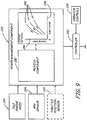
- FIG. 9 illustrate one embodiment of the power management component 222 that includes process component 280 that determines the power management output based upon an idle engine speed input 290, feedback engine RPMs from sensor 224 and throttle position from throttle position sensor 233.
- the illustrated control characteristics in FIG. 9 includes a plurality of control curves 292 providing a set point pump stroke (as illustrated by axis 294) for different engine RPM feedback (as illustrated by axis 296) for a plurality of idle engine speeds.
- the control curves provide a percentage pump stroke to destroke the engine based upon feedback RPMs from the RPM sensor 224 relative to demand engine speed based upon feedback from the throttle position sensor 233.
- the plurality of control curves 292 correspond to low, medium and high idle engine speeds 290, however application is not limited to the particular number of control curves or the embodiment shown.
- the process component 280 uses the low speed control curve to determine control input based upon the feedback engine RPMs from sensor 224. If the engine has a medium idle engine speed, the process component 280 uses the medium control curve to determine power management output based upon feedback engine RPMs. If the idle engine speed is high, the process component 280 uses the high speed control curve to determine the control input.
- control characteristics or methods include various equations or graphs that the process component 280 utilizes to determine output control parameters.
- control equations can determine control parameters for the drive pump 202 based upon a numerical or floating point idle engine speed and not a graded (e.g. low, medium or high) idle engine speed as illustrated in FIG. 9 .
Landscapes
- Engineering & Computer Science (AREA)
- General Engineering & Computer Science (AREA)
- Mechanical Engineering (AREA)
- Mining & Mineral Resources (AREA)
- Civil Engineering (AREA)
- Structural Engineering (AREA)
- Control Of Vehicle Engines Or Engines For Specific Uses (AREA)
- Operation Control Of Excavators (AREA)
- Control Of Eletrric Generators (AREA)
Description
- Power machines, such as work vehicles, loaders or diggers include multiple hydraulic circuits that are used to drive, steer and power work functions of the machine or vehicle. For example, different power machines or work vehicles use a hydrostatic drive assembly including a hydrostatic drive pump which supplies fluid to a hydrostatic motor to operate or drive the work vehicle or machine. Additionally, hydraulic cylinders are used to implement lift, tilt or other mechanical work functions. Fluid is supplied to the hydraulic cylinders via operation of additional work pumps.
- Each of the drive and additional work pumps are powered by the engine. Depending upon the work mode or function, the load on the engine can exceed power limits of the engine, causing the engine to stall. Depending upon the work application, it may be desirable to adjust different operating parameters to limit or reduce stall. The present invention addresses these and other problems and provides advantages over the prior art.
-
WO 2006/054711 relates to a control system for a hydraulic construction machine. When a mode select command selects an economy mode, a mode selecting section is turned on to output an engine speed correction value that is calculated by an engine speed correction value operating section. Further calculations are performed to obtain an engine speed which is reduced by mode selection to improve fuel consumption. A further control system is shown inUS 6 644 429 B2 . - The present invention is defined by the features of independent claim 1. Further preferred embodiments of the invention are defined in the dependent claims. In particular, the present invention relates to power management control for a power machine or vehicle. A user interface of the power machine or vehicle includes a power management selection for activating and deactivating power management control. Power management control is implemented through a power management control component based upon feedback from an RPM sensor. As disclosed in illustrative embodiments, the power management control component utilizes control methods and characteristics stored in system memory to determine control input to adjust hydrostatic parameters for power management.
-
-
FIG. 1 is an illustrative embodiment of a power machine or vehicle. -
FIG. 2 is a schematic illustration of a hydraulic circuit for a power machine or vehicle of the type illustrated inFIG. 1 . -
FIG. 3 is a schematic illustration of a power management control for a power machine or vehicle such as that illustrated inFIG. 1 . -
FIG. 4 is a schematic illustration of an embodiment of a user interface for a power machine or vehicle of the type illustrated inFIG. 1 including a power management selection and various operating controls. -
FIGS. 5-1 and 5-2 schematically illustrate embodiments of a power management selector for a user interface of a power machine or vehicle. -
FIG. 6 is a schematic illustration of a control embodiment including power management and speed control. -
FIG. 7 illustrates an embodiment of a selector including a power management selection, a speed control selection and no control selection. -
FIGS. 8 illustrates an embodiment of a power management component including control methods and characteristics. -
FIG. 9 illustrates an embodiment of a power management component including a plurality of control curves for different idle engine speeds. -
FIG. 1 illustrates an embodiment of a power machine orvehicle 100 in which the present invention can be incorporated or used. As shown the illustrated power machine includes abody 104 that is supported relative to a frame (not shown).Wheels 106 are coupled to the frame so that thepower machine 100 or vehicle can be driven over the ground during use. Application, however, of the present invention is not limited to a wheeled vehicle or loader as shown. For example, the present invention has application for a power machine, which moves along a track instead of wheels. - As shown in
FIG. 1 , the illustratedpower machine 100 includes alift arm assembly 110 that is used to raise, lower or position a work implement orattachment 112, (which in the illustrated embodiment is a bucket). Thelift arm assembly 110 includes lift arms 120 (only one of which is shown inFIG. 1 ).Lift arms 120 are pivotally coupled to thebody 104 of the machine to raise and lower theattachment 112. Hydraulic cylinders or actuators 124 (only one shown inFIG. 1 ) are coupled to thebody 104 and liftarms 120 to raise and lower thelift arms 120. InFIG. 1 , thelift arm assembly 110 is shown in the lowered position and shown in the raised position in phantom. The direction and speed of the vehicle is controlled through various operating controls on a user interface 130 (illustrated schematically) located in the cab or located remotely. Illustratively, the operating controls include joysticks, levers or pedals. - The attachment or
implement 112 is rotationally coupled to thelift arm assembly 110 so that an orientation of theimplement 112 can be adjusted relative to thelift arm assembly 110.Implement 112 is rotationally adjusted or tilted via a tilt cylinder (not shown inFIG. 1 ). The tilt cylinder is extended and retracted to adjust the orientation or tilt (e.g. curl or dump position) of the attachment or implement 112. AlthoughFIG. 1 illustrates a bucket attachment or implement, application is not limited to a bucket and other implements can be attached to thelift arm assembly 110 or machine depending upon the particular work application. For example,lift arm assembly 110 of the power machine can support a spade or other implement. - As shown in
FIG. 2 ,vehicle 100 is driven by a hydrostatic drive assembly and work functions are operated hydraulically. As shown, the hydrostatic drive assembly includes one or more or drive pumps orpumps 202 and a hydrostatic drive motor or motors 204 (both illustrated schematically). Output torque from the drive motor ormotors 204 is used to rotatewheels 106 of the power machine or vehicle through adrive transmission 205. - In the embodiment shown, the hydrostatic drive pump (or pumps) 202 is a variable displacement pump having a variable flow control component (not shown) or swashplate responsive to electronic control. The magnitude and direction of fluid flow from the
pump 202 is controlled through the various operating controls of theuser interface 130 to impart forward and reverse motion to the vehicle or power machine. The various operating controls of theuser interface 130 are operably coupled to the flow control component of thepump 202 to adjust the magnitude and direction of fluid flow to control the direction and speed of the vehicle. - As previously described, work functions of the vehicle or machine are actuated through various hydraulic circuitry. In the illustrated embodiment, the various hydraulic circuitry includes various hydraulic controls or circuitry 210 (illustrated schematically) that control fluid flow and direction to the
lift cylinder 124 and tilt cylinders 211 (illustrated schematically) based on input from the operating controls of theuser interface 130. Fluid is supplied to the hydraulic circuitry for lift and tilt functions viawork pump 212. Additionally, in the illustrated embodiment,work pump 212 supplies fluid toauxiliary hydraulics 214 to operate auxiliary functions for more complex implements or attachments based upon input from theuser interface 130. - As shown in
FIG. 2 , the hydrostatic drive pump(s) 202 and work pump(s) 212 are powered byengine 216. Speed (e.g. RPMS "revolutions-per-minute") of theengine 216 is controlled viathrottle input 218. Excessive load on the engine can decrease output RPMs of the engine making it difficult for the engine to keep up with the power demand of the hydrostatic drive assembly and other hydraulic systems. Such excessive demand on theengine 216 via the hydrostatic drive assembly or other systems (e.g. hydraulic controls andcircuitry 210 or auxiliary hydraulics 214) can cause theengine 216 to stall. -
FIG. 3 illustrates a power management system to control engine stall in response to excessive power demand where like numbers are used to refer to like parts in the previous FIGS. In the embodiment shown, thepump 202 is a variable displacement pump having a variable flow control component or swashplate (not shown) responsive to electronic control throughcontroller 220. As shown, thecontroller 220 receives input from various operating controls of theuser interface 130 to adjust or control the magnitude and direction of fluid flow frompump 202. - As shown, the power management function shown includes a
power management component 222 which receives engine RPMs feedback from asensor 224 and provides a control input to thecontroller 220 to adjust pump stroke or displacement to control power usage based upon the feedback engine RPMs. As described, thepower management component 220 receives feedback of the engine RPM to adjust pump displacement responsive to engine load or RPMs. - If there is a high demand or load on the
engine 216, engine RPMs decrease. In response to a decrease in engine RPMs, thepower management component 222 provides a control input to thecontroller 220 to adjust the flow control of thepump 202 to reduce the stroke or displacement of thepump 202 to manage power usage. In contrast, if engine RPMs are high, thepower management component 222 provides a control input so that the pump can operate at stroke commanded or selected by an operator through the operating controls of theuser interface 130. - In the control system shown in
FIG. 3 , pump stroke is automatically controlled based upon sensor feedback and operator input or commands from operating controls (e.g. joysticks) . Experience users are more skilled at controlling operation of the machine and can control the machine directly without control input from the power management component or other feedback. -
FIG. 4 illustrates a control embodiment for a power machine where like numbers are used to refer to like parts in the previous FIGS. In the illustrated embodiment, theuser interface 130 includes operating controls 230 (e.g. including various levers, pedals or joysticks) and apower management selection 232 that allows the user to activate or deactivate power management control depending upon preference or experience. When thepower management selection 232 is active, thepower management component 222 receives engine speed sensor feedback and provides control input tocontroller 220 to adjust pump stroke or displacement to control or manage power usage as previously described. When thepower management selection 232 is not selected, thecontroller 220 adjusts displacement ofpump 202 based upon operating control input without input from thepower management component 222 or other feedback. - In addition to feedback from the
engine RPM sensor 224, in the embodiment illustrated inFIG. 4 , thepower management component 222 receives input from athrottle position sensor 233 to control power usage. Input from thethrottle position sensor 233 andengine RPM sensor 224 provide an indication of demand engine speed verses actual engine speed for purposes of determining power demand and controlling power management. -
FIGS. 5-1 and 5-2 illustrate example embodiments of selectors of theuser interface 130 for selecting or activating power management control. In one embodiment shown inFIG. 5-1 , the selector includes arotatable selector dial 240 having a plurality of indicia including "on" indicia for activating power management control and "off" indicia for no control.Dial 240 is rotatable as illustrated byarrow 244 between multiple positions including the "on" position (as indicated by "on" indicia) to enable power management and "off" position (as indicated by "off" indicia). In the "off" position, thecontroller 220 does not use engine speed sensor feedback to control hydrostatic drive functions. - In another embodiment, as schematically illustrated in
FIG. 5-2 , the selector includes a selector switch or toggle 254 having an "on" position and an "off" position. In the illustrated embodiment in the "on" position, power management is active and thecontroller 220 receives control input from thepower management component 222 to manage power usage. In the "off" position,power management component 222 does not modify control input based upon engine speed feedback as previously described. AlthoughFIGS. 5-1 and 5-2 illustrate various selectors for power management selection, application is not limited to the particular embodiments shown and other selector devices can be used as will be appreciated by those skilled in the art. -
FIG. 6 schematically illustrates a control system including a plurality of control modes. In the embodiment shown, the system includes power management control implemented through thepower management component 222 and speed control implemented through aspeed control component 260. As shown, theuser interface 130 includes apower management selection 232, aspeed control selection 262 and a nocontrol selection 264. - As previously described, the power management selection activates power management control. The
speed control selection 262 activates a speed control mode. As shown in the speed control mode, thespeed control component 260 receives feedback from theengine RPM sensor 224 and is configured to determine a control input to thecontroller 220 to maintain or control speed. Thecontroller 220 uses the control input from thespeed control component 260 to adjust or control pump displacement or stroke to maintain a set speed defined by user input via the operating controls 230. Upon activation of the nocontrol selection 264, the controller receives input from operatingcontrols 230 but does not modify control input based upon feedback from sensors through thepower management component 222 and/orspeed control component 260. -
FIG. 7 schematically illustrates an embodiment of a mode selector including arotatable selector dial 270 for selecting power management control, speed control and no control. As shown, therotatable selector dial 270 includes a plurality of indicia including powermanagement control indicia 272,speed control indicia 274 and no control indicia 276 (e.g. "off").Selection dial 270 is rotated to align the indicia corresponding to the desired control mode with aselector mark 278 or other indicia. - As previously described, the
power management component 222 is configured to receive feedback fromsensors controller 220 to manage power usage. In an illustrated embodiment shown inFIG. 8 , thepower management component 222 includes aprocess component 280 that is configured to determine power management output based upon control methods or characteristic 282 stored in system memory. Illustratively, the control methods orcharacteristics 282 can store set point or control data or equations to optimize power usage or management. -
FIG. 9 illustrate one embodiment of thepower management component 222 that includesprocess component 280 that determines the power management output based upon an idleengine speed input 290, feedback engine RPMs fromsensor 224 and throttle position fromthrottle position sensor 233. The illustrated control characteristics inFIG. 9 includes a plurality ofcontrol curves 292 providing a set point pump stroke (as illustrated by axis 294) for different engine RPM feedback (as illustrated by axis 296) for a plurality of idle engine speeds. The control curves provide a percentage pump stroke to destroke the engine based upon feedback RPMs from theRPM sensor 224 relative to demand engine speed based upon feedback from thethrottle position sensor 233. In the illustrated embodiment shown, the plurality ofcontrol curves 292 correspond to low, medium and high idle engine speeds 290, however application is not limited to the particular number of control curves or the embodiment shown. - Thus, assuming the engine has a low idle engine speed, the
process component 280 uses the low speed control curve to determine control input based upon the feedback engine RPMs fromsensor 224. If the engine has a medium idle engine speed, theprocess component 280 uses the medium control curve to determine power management output based upon feedback engine RPMs. If the idle engine speed is high, theprocess component 280 uses the high speed control curve to determine the control input. - In an alternate embodiment, the control characteristics or methods include various equations or graphs that the
process component 280 utilizes to determine output control parameters. For example, illustratively, control equations can determine control parameters for thedrive pump 202 based upon a numerical or floating point idle engine speed and not a graded (e.g. low, medium or high) idle engine speed as illustrated inFIG. 9 . - Although the present invention has been described with reference to preferred embodiments, workers skilled in the art will recognize that changes may be made in form and detail without departing from scope of the invention.
Claims (6)
- A control assembly, for a power machine (100) having an engine (216), comprising an engine speed sensor (224) configured to provide feedback of a load on the engine, and a controller (220) configured to control a hydrostatic pump (202) of a hydrostatic drive assembly, the control assembly further comprising:a user interface (130) including operator controls (230) capable of providing a pump stroke or displacement input signal to the controller to control the magnitude and direction of flow from the hydrostatic pump and a mode selector (270) to select a power management control mode, a speed control mode and a no control mode; anda power management component (222) configured to receive the feedback from the engine speed sensor (224) and provide a control input to the controller (220) based on the feedback received from the engine speed sensor (224) when the power management control mode is selected; anda speed control component (260) configured to receive a feedback from the engine speed sensor (224) and provide a control input to the controller (220) based on the feedback received from the engine speed sensor (224) when the speed control mode is selected;wherein the controller (220) is configured to control the magnitude and direction of the hydrostatic pump stroke or displacement in response to the operator controls and wherein the controller (220) is configured, in the power management control mode, to destroke the pump to manage power usage and, in the speed control mode, to adjust the hydrostatic pump stroke to maintain a set engine speed in response to the feedback of the engine speed sensor (224) and, in the no control mode, not to provide any control input to the controller based upon the feedback from the engine speed sensor (224).
- The control assembly of claim 1 wherein the power management component includes a process component (280) and control methods and characteristics and the process component determines the power management component output based upon the control methods and characteristics stored in system memory.
- The control assembly of claim 2 wherein the control methods and characteristics include at least one control curve (292) or data that correlates different engine speeds relative to different pump strokes or displacements and the engine speed sensor (224) provides an engine speed feedback and the power management component output is determined based upon the engine speed feedback using the at least one control curve or data that correlates the different engine speeds relative to the different pump strokes or displacements.
- The control assembly of claim 2 wherein the power management component (222) receives feedback from a throttle position sensor (233) and the control methods and characteristics provide a pump stroke or displacement based upon engine speed feedback from the engine speed sensor (224) relative to a demand engine speed provided from the throttle position sensor (233) and the power management component output corresponds to the pump stroke or displacement for the engine speed feedback relative to the demand engine speed from the throttle position sensor (233).
- The control assembly of claim 1 including a plurality of sensing devices including a throttle position sensor (233) and the power management component uses the feedback from the throttle position sensor (233) and the engine speed sensor (224) to determine the engine load to provide the power management component output corresponding to the feedback from the throttle position sensor (233) and the engine speed sensor (224).
- The control assembly of claim 1 wherein the pump displacement or stroke input device comprises a joystick control device.
Applications Claiming Priority (2)
| Application Number | Priority Date | Filing Date | Title |
|---|---|---|---|
| US11/696,414 US8718878B2 (en) | 2007-04-04 | 2007-04-04 | Power machine or vehicle with power management |
| PCT/US2008/004329 WO2008124024A2 (en) | 2007-04-04 | 2008-04-03 | Power machine or vehicle with power management |
Publications (2)
| Publication Number | Publication Date |
|---|---|
| EP2155972A2 EP2155972A2 (en) | 2010-02-24 |
| EP2155972B1 true EP2155972B1 (en) | 2019-12-25 |
Family
ID=39522042
Family Applications (1)
| Application Number | Title | Priority Date | Filing Date |
|---|---|---|---|
| EP08742519.5A Active EP2155972B1 (en) | 2007-04-04 | 2008-04-03 | Power machine or vehicle with power management |
Country Status (6)
| Country | Link |
|---|---|
| US (1) | US8718878B2 (en) |
| EP (1) | EP2155972B1 (en) |
| CN (1) | CN101652521B (en) |
| CA (1) | CA2682682A1 (en) |
| ES (1) | ES2773668T3 (en) |
| WO (1) | WO2008124024A2 (en) |
Families Citing this family (7)
| Publication number | Priority date | Publication date | Assignee | Title |
|---|---|---|---|---|
| US9572532B2 (en) * | 2009-01-23 | 2017-02-21 | Qualcomm Incorporated | Button sensor |
| US20120323464A1 (en) * | 2011-06-20 | 2012-12-20 | Chad Christopher Steen | Multiple mode throttle control |
| CN104160183B (en) * | 2012-03-07 | 2017-08-25 | 克拉克设备公司 | Power management for drive system |
| US10380511B2 (en) * | 2012-03-08 | 2019-08-13 | Husqvarna Ab | Outdoor power equipment fleet management system with operator performance monitoring |
| CN105102729B (en) * | 2013-11-15 | 2017-03-08 | 株式会社小松制作所 | Working truck and its control method |
| US10340101B2 (en) * | 2015-07-31 | 2019-07-02 | Intel Corporation | Keycap with active elements |
| WO2020065913A1 (en) * | 2018-09-28 | 2020-04-02 | 日立建機株式会社 | Cargo work vehicle |
Citations (3)
| Publication number | Priority date | Publication date | Assignee | Title |
|---|---|---|---|---|
| US4606313A (en) * | 1980-10-09 | 1986-08-19 | Hitachi Construction Machinery Co., Ltd. | Method of and system for controlling hydraulic power system |
| US4702843A (en) * | 1985-06-21 | 1987-10-27 | Standard Manufacturing Co., Inc. | Control system for an adverse terrain vehicle |
| WO2005056933A1 (en) * | 2003-12-09 | 2005-06-23 | Komatsu Ltd. | Device and method of controlling hydraulic drive of construction machinery |
Family Cites Families (31)
| Publication number | Priority date | Publication date | Assignee | Title |
|---|---|---|---|---|
| US4185521A (en) * | 1975-03-10 | 1980-01-29 | Caterpillar Tractor Co. | Hydraulic control system for a hydrostatic-mechanical transmission |
| US4189921A (en) * | 1976-07-02 | 1980-02-26 | Eaton Corporation | Hydraulic controller |
| US4425620A (en) * | 1981-01-28 | 1984-01-10 | Steiger Tractor, Inc. | Electrical control for power shift transmission |
| US4462210A (en) * | 1981-07-31 | 1984-07-31 | Sundstrand Corporation | Input torque control for a variable displacement hydraulic transmission |
| US4474104A (en) * | 1983-04-11 | 1984-10-02 | Double A Products Co. | Control system for variable displacement pumps and motors |
| US4648040A (en) * | 1984-02-21 | 1987-03-03 | J. I. Case Company | Engine monitor/control microprocessor for continuously variable power train |
| GB2186777B (en) * | 1986-02-20 | 1989-11-22 | Massey Ferguson Services Nv | Ground speed control |
| US4740898A (en) * | 1986-07-17 | 1988-04-26 | Deere & Company | Automatic engine/transmission control system |
| US4777866A (en) * | 1986-09-30 | 1988-10-18 | Nanjing Automobile Research Institute | Variable displacement radial piston pumps or motors |
| GB2234328B (en) * | 1989-07-12 | 1993-09-08 | Johnston Eng Ltd | Improvements in vehicle control systems |
| JP2520771B2 (en) | 1990-07-18 | 1996-07-31 | 株式会社小松製作所 | Control method and apparatus for loading work vehicle |
| US5335750A (en) * | 1992-06-11 | 1994-08-09 | Sauer Inc. | Dual mode transmission control |
| DE4226453A1 (en) * | 1992-08-10 | 1994-02-17 | Sauer Sundstrand Gmbh & Co | Hydraulic transmission for fork lift truck - has variable pump and electronic control of transmission ratio |
| JP3925666B2 (en) * | 1997-01-20 | 2007-06-06 | 株式会社小松製作所 | Control device for engine and variable displacement pump |
| JPH11222045A (en) * | 1998-02-10 | 1999-08-17 | Kubota Corp | Work vehicle |
| US6321866B1 (en) * | 1998-10-21 | 2001-11-27 | Ag-Chem Equipment Co., Inc. | Hydrostatic power distribution/control logic system |
| US20010043721A1 (en) * | 2000-03-21 | 2001-11-22 | Sarnoff Corporation | Method and apparatus for performing motion analysis on an image sequence |
| JP4098955B2 (en) * | 2000-12-18 | 2008-06-11 | 日立建機株式会社 | Construction machine control equipment |
| US20040125228A1 (en) * | 2001-07-25 | 2004-07-01 | Robert Dougherty | Apparatus and method for determining the range of remote objects |
| US6644429B2 (en) * | 2002-01-28 | 2003-11-11 | Deere & Co | Hydrostatic auxiliary drive system |
| US20040098984A1 (en) * | 2002-11-26 | 2004-05-27 | Duell Charles A. | Combination hydraulic system and electronically controlled vehicle and method of operating same |
| US6975246B1 (en) * | 2003-05-13 | 2005-12-13 | Itt Manufacturing Enterprises, Inc. | Collision avoidance using limited range gated video |
| JP4163073B2 (en) * | 2003-08-12 | 2008-10-08 | 日立建機株式会社 | Control device for work vehicle |
| US20050057094A1 (en) * | 2003-09-16 | 2005-03-17 | Koelzer Robert L. | System for regulating the supply of power to a brake system |
| GB2427187B (en) * | 2004-04-08 | 2008-06-18 | Komatsu Mfg Co Ltd | Hydraulic drive device for work machine |
| US7316113B2 (en) * | 2004-07-14 | 2008-01-08 | Komatsu Ltd. | Control device for a work machine hydraulic pump used in a work vehicle |
| US8102423B2 (en) * | 2004-08-10 | 2012-01-24 | Sri International | Method and system for performing adaptive image acquisition |
| JP4188902B2 (en) | 2004-11-22 | 2008-12-03 | 日立建機株式会社 | Control equipment for hydraulic construction machinery |
| US20080319618A1 (en) * | 2006-02-20 | 2008-12-25 | Volvo Construction Equipment Ab | Method for Optimizing Operation of a Work Vehicle |
| US20100121574A1 (en) * | 2006-09-05 | 2010-05-13 | Honeywell International Inc. | Method for collision avoidance of unmanned aerial vehicle with other aircraft |
| US20100250022A1 (en) * | 2006-12-29 | 2010-09-30 | Air Recon, Inc. | Useful unmanned aerial vehicle |
-
2007
- 2007-04-04 US US11/696,414 patent/US8718878B2/en active Active
-
2008
- 2008-04-03 ES ES08742519T patent/ES2773668T3/en active Active
- 2008-04-03 EP EP08742519.5A patent/EP2155972B1/en active Active
- 2008-04-03 CN CN2008800110112A patent/CN101652521B/en active Active
- 2008-04-03 WO PCT/US2008/004329 patent/WO2008124024A2/en not_active Ceased
- 2008-04-03 CA CA002682682A patent/CA2682682A1/en not_active Abandoned
Patent Citations (4)
| Publication number | Priority date | Publication date | Assignee | Title |
|---|---|---|---|---|
| US4606313A (en) * | 1980-10-09 | 1986-08-19 | Hitachi Construction Machinery Co., Ltd. | Method of and system for controlling hydraulic power system |
| US4702843A (en) * | 1985-06-21 | 1987-10-27 | Standard Manufacturing Co., Inc. | Control system for an adverse terrain vehicle |
| WO2005056933A1 (en) * | 2003-12-09 | 2005-06-23 | Komatsu Ltd. | Device and method of controlling hydraulic drive of construction machinery |
| US20070101708A1 (en) * | 2003-12-09 | 2007-05-10 | Komatsu Ltd. | Device and method of controlling hydraulic drive of construction machinery |
Also Published As
| Publication number | Publication date |
|---|---|
| WO2008124024A2 (en) | 2008-10-16 |
| EP2155972A2 (en) | 2010-02-24 |
| US8718878B2 (en) | 2014-05-06 |
| CA2682682A1 (en) | 2008-10-16 |
| CN101652521A (en) | 2010-02-17 |
| CN101652521B (en) | 2012-12-19 |
| US20080250259A1 (en) | 2008-10-09 |
| ES2773668T3 (en) | 2020-07-14 |
| WO2008124024A3 (en) | 2008-12-11 |
Similar Documents
| Publication | Publication Date | Title |
|---|---|---|
| US6498973B2 (en) | Flow control for electro-hydraulic systems | |
| EP3438352B1 (en) | System for changing output characteristics of construction machinery | |
| JP6049758B2 (en) | Achieving maximum lifting speed using a single input | |
| KR101039300B1 (en) | Working machine with prime mover control | |
| US8718878B2 (en) | Power machine or vehicle with power management | |
| KR100739419B1 (en) | Hydraulic driving control device and hydraulic shovel with the control device | |
| WO2005098148A1 (en) | Hydraulic drive device for working machine | |
| WO2002021023A1 (en) | Speed controller of wheel type hydraulic traveling vehicle | |
| US20080154466A1 (en) | System and method for controlling a machine | |
| WO2014149125A1 (en) | Lift arm structure with an articulated knee portion for a power machine | |
| US10633827B2 (en) | Temperature responsive hydraulic derate | |
| JP7085996B2 (en) | Work machine and control method of work machine | |
| CN102016186B (en) | Method for controlling a working machine | |
| KR20110021788A (en) | Method for controlling the hydraulic system | |
| CN100402763C (en) | Construction machinery | |
| JP2008151211A (en) | Engine start system for construction machinery | |
| KR100805990B1 (en) | Controller for hydraulic drive system | |
| JP3539720B2 (en) | Control equipment for construction machinery | |
| JP6691482B2 (en) | Work vehicle and operation control method | |
| JP3634980B2 (en) | Construction machine control equipment | |
| JP4127771B2 (en) | Engine control device for construction machinery | |
| JPH0783084A (en) | Hydraulic construction machinery | |
| JP4242038B2 (en) | Wheeled hydraulic construction machine | |
| EP3865628B1 (en) | Control method for construction machinery and control system for construction machinery | |
| CN113906184B (en) | Load carrying vehicle |
Legal Events
| Date | Code | Title | Description |
|---|---|---|---|
| PUAI | Public reference made under article 153(3) epc to a published international application that has entered the european phase |
Free format text: ORIGINAL CODE: 0009012 |
|
| 17P | Request for examination filed |
Effective date: 20091104 |
|
| AK | Designated contracting states |
Kind code of ref document: A2 Designated state(s): AT BE BG CH CY CZ DE DK EE ES FI FR GB GR HR HU IE IS IT LI LT LU LV MC MT NL NO PL PT RO SE SI SK TR |
|
| AX | Request for extension of the european patent |
Extension state: AL BA MK RS |
|
| DAX | Request for extension of the european patent (deleted) | ||
| STAA | Information on the status of an ep patent application or granted ep patent |
Free format text: STATUS: EXAMINATION IS IN PROGRESS |
|
| 17Q | First examination report despatched |
Effective date: 20170220 |
|
| REG | Reference to a national code |
Ref country code: DE Ref legal event code: R079 Ref document number: 602008061876 Country of ref document: DE Free format text: PREVIOUS MAIN CLASS: E02F0009200000 Ipc: B60W0030140000 |
|
| GRAP | Despatch of communication of intention to grant a patent |
Free format text: ORIGINAL CODE: EPIDOSNIGR1 |
|
| STAA | Information on the status of an ep patent application or granted ep patent |
Free format text: STATUS: GRANT OF PATENT IS INTENDED |
|
| RIC1 | Information provided on ipc code assigned before grant |
Ipc: F16H 61/465 20100101ALI20190624BHEP Ipc: F16H 61/475 20100101ALI20190624BHEP Ipc: E02F 9/22 20060101ALI20190624BHEP Ipc: B60W 30/14 20060101AFI20190624BHEP Ipc: F16H 61/431 20100101ALI20190624BHEP |
|
| INTG | Intention to grant announced |
Effective date: 20190723 |
|
| GRAS | Grant fee paid |
Free format text: ORIGINAL CODE: EPIDOSNIGR3 |
|
| GRAA | (expected) grant |
Free format text: ORIGINAL CODE: 0009210 |
|
| STAA | Information on the status of an ep patent application or granted ep patent |
Free format text: STATUS: THE PATENT HAS BEEN GRANTED |
|
| AK | Designated contracting states |
Kind code of ref document: B1 Designated state(s): AT BE BG CH CY CZ DE DK EE ES FI FR GB GR HR HU IE IS IT LI LT LU LV MC MT NL NO PL PT RO SE SI SK TR |
|
| REG | Reference to a national code |
Ref country code: GB Ref legal event code: FG4D |
|
| REG | Reference to a national code |
Ref country code: CH Ref legal event code: EP |
|
| REG | Reference to a national code |
Ref country code: AT Ref legal event code: REF Ref document number: 1216816 Country of ref document: AT Kind code of ref document: T Effective date: 20200115 |
|
| REG | Reference to a national code |
Ref country code: DE Ref legal event code: R096 Ref document number: 602008061876 Country of ref document: DE |
|
| REG | Reference to a national code |
Ref country code: IE Ref legal event code: FG4D |
|
| REG | Reference to a national code |
Ref country code: NL Ref legal event code: MP Effective date: 20191225 |
|
| PG25 | Lapsed in a contracting state [announced via postgrant information from national office to epo] |
Ref country code: LT Free format text: LAPSE BECAUSE OF FAILURE TO SUBMIT A TRANSLATION OF THE DESCRIPTION OR TO PAY THE FEE WITHIN THE PRESCRIBED TIME-LIMIT Effective date: 20191225 Ref country code: FI Free format text: LAPSE BECAUSE OF FAILURE TO SUBMIT A TRANSLATION OF THE DESCRIPTION OR TO PAY THE FEE WITHIN THE PRESCRIBED TIME-LIMIT Effective date: 20191225 Ref country code: BG Free format text: LAPSE BECAUSE OF FAILURE TO SUBMIT A TRANSLATION OF THE DESCRIPTION OR TO PAY THE FEE WITHIN THE PRESCRIBED TIME-LIMIT Effective date: 20200325 Ref country code: SE Free format text: LAPSE BECAUSE OF FAILURE TO SUBMIT A TRANSLATION OF THE DESCRIPTION OR TO PAY THE FEE WITHIN THE PRESCRIBED TIME-LIMIT Effective date: 20191225 Ref country code: LV Free format text: LAPSE BECAUSE OF FAILURE TO SUBMIT A TRANSLATION OF THE DESCRIPTION OR TO PAY THE FEE WITHIN THE PRESCRIBED TIME-LIMIT Effective date: 20191225 Ref country code: GR Free format text: LAPSE BECAUSE OF FAILURE TO SUBMIT A TRANSLATION OF THE DESCRIPTION OR TO PAY THE FEE WITHIN THE PRESCRIBED TIME-LIMIT Effective date: 20200326 Ref country code: NO Free format text: LAPSE BECAUSE OF FAILURE TO SUBMIT A TRANSLATION OF THE DESCRIPTION OR TO PAY THE FEE WITHIN THE PRESCRIBED TIME-LIMIT Effective date: 20200325 |
|
| REG | Reference to a national code |
Ref country code: LT Ref legal event code: MG4D |
|
| PG25 | Lapsed in a contracting state [announced via postgrant information from national office to epo] |
Ref country code: HR Free format text: LAPSE BECAUSE OF FAILURE TO SUBMIT A TRANSLATION OF THE DESCRIPTION OR TO PAY THE FEE WITHIN THE PRESCRIBED TIME-LIMIT Effective date: 20191225 |
|
| REG | Reference to a national code |
Ref country code: ES Ref legal event code: FG2A Ref document number: 2773668 Country of ref document: ES Kind code of ref document: T3 Effective date: 20200714 |
|
| PG25 | Lapsed in a contracting state [announced via postgrant information from national office to epo] |
Ref country code: NL Free format text: LAPSE BECAUSE OF FAILURE TO SUBMIT A TRANSLATION OF THE DESCRIPTION OR TO PAY THE FEE WITHIN THE PRESCRIBED TIME-LIMIT Effective date: 20191225 Ref country code: EE Free format text: LAPSE BECAUSE OF FAILURE TO SUBMIT A TRANSLATION OF THE DESCRIPTION OR TO PAY THE FEE WITHIN THE PRESCRIBED TIME-LIMIT Effective date: 20191225 Ref country code: RO Free format text: LAPSE BECAUSE OF FAILURE TO SUBMIT A TRANSLATION OF THE DESCRIPTION OR TO PAY THE FEE WITHIN THE PRESCRIBED TIME-LIMIT Effective date: 20191225 Ref country code: PT Free format text: LAPSE BECAUSE OF FAILURE TO SUBMIT A TRANSLATION OF THE DESCRIPTION OR TO PAY THE FEE WITHIN THE PRESCRIBED TIME-LIMIT Effective date: 20200520 Ref country code: CZ Free format text: LAPSE BECAUSE OF FAILURE TO SUBMIT A TRANSLATION OF THE DESCRIPTION OR TO PAY THE FEE WITHIN THE PRESCRIBED TIME-LIMIT Effective date: 20191225 |
|
| PGFP | Annual fee paid to national office [announced via postgrant information from national office to epo] |
Ref country code: ES Payment date: 20200504 Year of fee payment: 13 |
|
| PG25 | Lapsed in a contracting state [announced via postgrant information from national office to epo] |
Ref country code: SK Free format text: LAPSE BECAUSE OF FAILURE TO SUBMIT A TRANSLATION OF THE DESCRIPTION OR TO PAY THE FEE WITHIN THE PRESCRIBED TIME-LIMIT Effective date: 20191225 Ref country code: IS Free format text: LAPSE BECAUSE OF FAILURE TO SUBMIT A TRANSLATION OF THE DESCRIPTION OR TO PAY THE FEE WITHIN THE PRESCRIBED TIME-LIMIT Effective date: 20200425 |
|
| PGFP | Annual fee paid to national office [announced via postgrant information from national office to epo] |
Ref country code: IT Payment date: 20200423 Year of fee payment: 13 |
|
| REG | Reference to a national code |
Ref country code: DE Ref legal event code: R097 Ref document number: 602008061876 Country of ref document: DE |
|
| PG25 | Lapsed in a contracting state [announced via postgrant information from national office to epo] |
Ref country code: DK Free format text: LAPSE BECAUSE OF FAILURE TO SUBMIT A TRANSLATION OF THE DESCRIPTION OR TO PAY THE FEE WITHIN THE PRESCRIBED TIME-LIMIT Effective date: 20191225 |
|
| PLBE | No opposition filed within time limit |
Free format text: ORIGINAL CODE: 0009261 |
|
| STAA | Information on the status of an ep patent application or granted ep patent |
Free format text: STATUS: NO OPPOSITION FILED WITHIN TIME LIMIT |
|
| REG | Reference to a national code |
Ref country code: AT Ref legal event code: MK05 Ref document number: 1216816 Country of ref document: AT Kind code of ref document: T Effective date: 20191225 |
|
| PG25 | Lapsed in a contracting state [announced via postgrant information from national office to epo] |
Ref country code: MC Free format text: LAPSE BECAUSE OF FAILURE TO SUBMIT A TRANSLATION OF THE DESCRIPTION OR TO PAY THE FEE WITHIN THE PRESCRIBED TIME-LIMIT Effective date: 20191225 Ref country code: SI Free format text: LAPSE BECAUSE OF FAILURE TO SUBMIT A TRANSLATION OF THE DESCRIPTION OR TO PAY THE FEE WITHIN THE PRESCRIBED TIME-LIMIT Effective date: 20191225 |
|
| REG | Reference to a national code |
Ref country code: CH Ref legal event code: PL |
|
| 26N | No opposition filed |
Effective date: 20200928 |
|
| PG25 | Lapsed in a contracting state [announced via postgrant information from national office to epo] |
Ref country code: CH Free format text: LAPSE BECAUSE OF NON-PAYMENT OF DUE FEES Effective date: 20200430 Ref country code: LI Free format text: LAPSE BECAUSE OF NON-PAYMENT OF DUE FEES Effective date: 20200430 Ref country code: AT Free format text: LAPSE BECAUSE OF FAILURE TO SUBMIT A TRANSLATION OF THE DESCRIPTION OR TO PAY THE FEE WITHIN THE PRESCRIBED TIME-LIMIT Effective date: 20191225 Ref country code: LU Free format text: LAPSE BECAUSE OF NON-PAYMENT OF DUE FEES Effective date: 20200403 |
|
| REG | Reference to a national code |
Ref country code: BE Ref legal event code: MM Effective date: 20200430 |
|
| PG25 | Lapsed in a contracting state [announced via postgrant information from national office to epo] |
Ref country code: PL Free format text: LAPSE BECAUSE OF FAILURE TO SUBMIT A TRANSLATION OF THE DESCRIPTION OR TO PAY THE FEE WITHIN THE PRESCRIBED TIME-LIMIT Effective date: 20191225 Ref country code: BE Free format text: LAPSE BECAUSE OF NON-PAYMENT OF DUE FEES Effective date: 20200430 |
|
| PG25 | Lapsed in a contracting state [announced via postgrant information from national office to epo] |
Ref country code: IE Free format text: LAPSE BECAUSE OF NON-PAYMENT OF DUE FEES Effective date: 20200403 |
|
| PG25 | Lapsed in a contracting state [announced via postgrant information from national office to epo] |
Ref country code: TR Free format text: LAPSE BECAUSE OF FAILURE TO SUBMIT A TRANSLATION OF THE DESCRIPTION OR TO PAY THE FEE WITHIN THE PRESCRIBED TIME-LIMIT Effective date: 20191225 Ref country code: MT Free format text: LAPSE BECAUSE OF FAILURE TO SUBMIT A TRANSLATION OF THE DESCRIPTION OR TO PAY THE FEE WITHIN THE PRESCRIBED TIME-LIMIT Effective date: 20191225 Ref country code: CY Free format text: LAPSE BECAUSE OF FAILURE TO SUBMIT A TRANSLATION OF THE DESCRIPTION OR TO PAY THE FEE WITHIN THE PRESCRIBED TIME-LIMIT Effective date: 20191225 |
|
| REG | Reference to a national code |
Ref country code: ES Ref legal event code: FD2A Effective date: 20220630 |
|
| PG25 | Lapsed in a contracting state [announced via postgrant information from national office to epo] |
Ref country code: ES Free format text: LAPSE BECAUSE OF NON-PAYMENT OF DUE FEES Effective date: 20210404 |
|
| PG25 | Lapsed in a contracting state [announced via postgrant information from national office to epo] |
Ref country code: IT Free format text: LAPSE BECAUSE OF NON-PAYMENT OF DUE FEES Effective date: 20200403 |
|
| REG | Reference to a national code |
Ref country code: DE Ref legal event code: R081 Ref document number: 602008061876 Country of ref document: DE Owner name: DOOSAN BOBCAT NORTH AMERICA, INC. (N.D.GES.D.S, US Free format text: FORMER OWNER: CLARK EQUIPMENT COMPANY, WEST FARGO, N.D., US |
|
| PGFP | Annual fee paid to national office [announced via postgrant information from national office to epo] |
Ref country code: DE Payment date: 20250429 Year of fee payment: 18 |
|
| PGFP | Annual fee paid to national office [announced via postgrant information from national office to epo] |
Ref country code: GB Payment date: 20250428 Year of fee payment: 18 |
|
| PGFP | Annual fee paid to national office [announced via postgrant information from national office to epo] |
Ref country code: FR Payment date: 20250425 Year of fee payment: 18 |
|
| PG25 | Lapsed in a contracting state [announced via postgrant information from national office to epo] |
Ref country code: IT Free format text: LAPSE BECAUSE OF NON-PAYMENT OF DUE FEES Effective date: 20210403 |