EP2155597B2 - Load monitoring system - Google Patents
Load monitoring system Download PDFInfo
- Publication number
- EP2155597B2 EP2155597B2 EP08775763.9A EP08775763A EP2155597B2 EP 2155597 B2 EP2155597 B2 EP 2155597B2 EP 08775763 A EP08775763 A EP 08775763A EP 2155597 B2 EP2155597 B2 EP 2155597B2
- Authority
- EP
- European Patent Office
- Prior art keywords
- load
- signal
- monitoring system
- strain
- load monitoring
- Prior art date
- Legal status (The legal status is an assumption and is not a legal conclusion. Google has not performed a legal analysis and makes no representation as to the accuracy of the status listed.)
- Active
Links
Images


Classifications
-
- B—PERFORMING OPERATIONS; TRANSPORTING
- B66—HOISTING; LIFTING; HAULING
- B66F—HOISTING, LIFTING, HAULING OR PUSHING, NOT OTHERWISE PROVIDED FOR, e.g. DEVICES WHICH APPLY A LIFTING OR PUSHING FORCE DIRECTLY TO THE SURFACE OF A LOAD
- B66F17/00—Safety devices, e.g. for limiting or indicating lifting force
- B66F17/006—Safety devices, e.g. for limiting or indicating lifting force for working platforms
-
- B—PERFORMING OPERATIONS; TRANSPORTING
- B66—HOISTING; LIFTING; HAULING
- B66F—HOISTING, LIFTING, HAULING OR PUSHING, NOT OTHERWISE PROVIDED FOR, e.g. DEVICES WHICH APPLY A LIFTING OR PUSHING FORCE DIRECTLY TO THE SURFACE OF A LOAD
- B66F11/00—Lifting devices specially adapted for particular uses not otherwise provided for
- B66F11/04—Lifting devices specially adapted for particular uses not otherwise provided for for movable platforms or cabins, e.g. on vehicles, permitting workmen to place themselves in any desired position for carrying out required operations
- B66F11/044—Working platforms suspended from booms
- B66F11/046—Working platforms suspended from booms of the telescoping type
-
- G—PHYSICS
- G01—MEASURING; TESTING
- G01G—WEIGHING
- G01G3/00—Weighing apparatus characterised by the use of elastically-deformable members, e.g. spring balances
- G01G3/12—Weighing apparatus characterised by the use of elastically-deformable members, e.g. spring balances wherein the weighing element is in the form of a solid body stressed by pressure or tension during weighing
- G01G3/14—Weighing apparatus characterised by the use of elastically-deformable members, e.g. spring balances wherein the weighing element is in the form of a solid body stressed by pressure or tension during weighing measuring variations of electrical resistance
- G01G3/142—Circuits specially adapted therefor
- G01G3/145—Circuits specially adapted therefor involving comparison with a reference value
-
- G—PHYSICS
- G01—MEASURING; TESTING
- G01L—MEASURING FORCE, STRESS, TORQUE, WORK, MECHANICAL POWER, MECHANICAL EFFICIENCY, OR FLUID PRESSURE
- G01L1/00—Measuring force or stress, in general
- G01L1/20—Measuring force or stress, in general by measuring variations in ohmic resistance of solid materials or of electrically-conductive fluids; by making use of electrokinetic cells, i.e. liquid-containing cells wherein an electrical potential is produced or varied upon the application of stress
- G01L1/22—Measuring force or stress, in general by measuring variations in ohmic resistance of solid materials or of electrically-conductive fluids; by making use of electrokinetic cells, i.e. liquid-containing cells wherein an electrical potential is produced or varied upon the application of stress using resistance strain gauges
- G01L1/225—Measuring circuits therefor
- G01L1/2262—Measuring circuits therefor involving simple electrical bridges
Definitions
- the present invention relates to a load monitoring system for a mobile work platform and to a mobile work platform having a load monitoring system.
- Mobile work platforms typically include a cage or platform that is designed to receive one or more human operators.
- the cage is mounted on a lift mechanism, such as a hydraulic boom or a scissor lift mechanism, that allows its height to be adjusted.
- the mobile work platform also includes a wheeled or tracked chassis, which allows it to be moved easily to a desired location.
- Various types of mobile work platform are available, including self-propelled, self-drive, trailer and vehicle-mounted platforms.
- a load monitoring system is generally included to provide cage overload protection.
- Cage overload protection is required on mobile elevating work platforms as defined by European standard EN280:2001 Amendment 1.
- European standard EN954 is cited by EN 280 and describes the requirements for safety switches in electrical systems providing overload protection.
- EN954 Category 3 requires that common mode faults resulting from damage to the protection system are taken into account, if the probability of such a fault occurring is significant.
- US 2003/0174064 A1 describes an overload detection device for a high-lift work vehicle, including a load sensor comprising a distortion gauge pasted onto a plate member to detect flexure thereof.
- US5296655 describes a control system for testing, calibration and operation of a weighing apparatus.
- US4696359 describes an electronic weighing apparatus that includes a zero tracking circuit.
- the invention seeks to provide a detector within the load monitoring system for detecting any unsafe damage to the load monitoring system that may result in an unstable work platform.
- the unloaded strain signal is the strain signal provided by the strain gauge when the cage of the mobile work platform is empty.
- a shift in the unloaded strain signal may occur when, for example, the load cell is damaged causing the zero position of the load cell to shift.
- a negative shift in the unloaded strain signal causes the load cell to sense less than the full weight of the cage, with the result that when the cage is empty the strain gauge indicates a negative load value.
- a second sensing device that senses a negative shift in the unloaded strain signal ensures that any damage to the load cell that would cause it to detect less than the actual load in the cage is automatically detected. This prevents the load monitoring system from giving a false reading and ensures that the cage is not inadvertently overloaded. The safety of the mobile work platform is thus improved and the risk of accidents is reduced.
- the strain gauge is preferably connected in a bridge circuit configuration, which preferably provides compensation for temperature variations.
- the strain gauge is connected to an amplifier that is constructed and arranged to amplify the strain signal.
- the first sensing device may be a first comparator.
- the first comparator has a first input terminal connected to receive a load signal that represents the strain in the strain gauge, a second input terminal connected to receive a load reference signal, and an output terminal for an overload signal that is generated when the load signal exceeds the load reference signal.
- the load reference signal may be adjustable, allowing the required load limit to be selected.
- the output signal of the first comparator is connected to a safety device that is constructed and arranged for activation by said overload signal, thereby informing the operator of a potentially hazardous overload situation and allowing remedial action to be taken.
- the safety device may for example be an alarm and/or an automatic cut-out device.
- the second sensing device may be a second comparator.
- the second comparator has a first input terminal connected to receive a load signal that represents the strain in the strain gauge, a second input terminal connected to receive a second reference signal, and an output terminal for a negative shift signal that is generated when the load signal is less than the second reference signal.
- the second reference signal may be adjustable, allowing an acceptable limit of negative shift in the unloaded strain signal to be selected.
- the output signal of the second comparator is connected to a safety device that is constructed and arranged for activation by said negative shift signal. Again, this informs the operator of the potentially hazardous situation, allowing suitable remedial action such as repairing or replacing the damaged load cell to be taken.
- the safety device may for example be an alarm and/or an automatic cut-out device.
- the system preferably includes at least two strain gauges, each being connected to a respective load sensing circuit, wherein the load sensing circuits are constructed and arranged to operate in parallel. This ensures that the monitoring system operates correctly even if one of the circuits is faulty, thus increasing safety.
- a mobile work platform that includes an operator platform, a base and a lift mechanism for lifting the operator platform relative to the base, and a load monitoring system according to any one of the preceding statements of invention for monitoring the load on the operator platform.
- the load cell of the load monitoring system is connected between the lift mechanism and the operator platform.
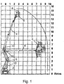
- FIG. 1 shows a typical mobile work platform according to an embodiment of the invention, which includes a wheeled base unit 2, a hydraulically operated lift mechanism comprising a boom 4 and a lifting structure 5, and a platform (or cage) 6 for a human operator 8.
- the boom 4 which is shown here in various operating configurations, may be retracted and folded onto the base unit 2 for transportation or storage. Movement of the boom 4 is controlled by various hydraulic cylinders 10, which are connected by hydraulic hoses (not shown) to a hydraulic drive system. Hydraulic motors may also be provided for driving the wheels.
- the components shown in Figure 1 are all conventional and will not therefore be described in detail. It should be understood that the mobile work platform may take various alternative forms.
- the cage 6 is connected to the boom 4 via a load cell 12.
- the load cell 12 is conventional in design and comprises an aluminium block that acts as a cantilever spring and carries one or more strain gauges, preferably of the resistive foil type.
- the strain gauges are connected to a load monitoring system 14, for example as illustrated in figure 3 .
- the load cell 12 supports a downwards load mg equal to the mass m of the cage and its contents multiplied by gravity g. It therefore experiences a positive moment M + (shown as clockwise in the drawing).
- M + shown as clockwise in the drawing.
- the strain in the load cell produced by this moment is measured by the strain gauges and used to calculate the load in the cage. If the load exceeds a predetermined limit, the load monitoring system 14 sounds an alarm to warn the user and/or activates a cut-out device to prevent further operation of the platform.
- the cage Under certain circumstances, it is possible for the cage to experience a force that results in a negative moment being applied to the load cell 12. For example, as illustrated in figure 2b , if the mobile work platform is accidentally pushed or driven backwards into an obstruction, a force F may be applied to the cage 6, producing a negative moment M - on the load cell 12. If this negative moment exceeds the elastic limit of the load cell it may be permanently deformed. This may affect the zero condition of the strain gauges, such that they read zero only when the cage 6 is partially loaded. As a result, it may be possible to overload the cage without activating the safety system, creating a potentially dangerous situation.
- the cage overload alarm will not be activated until the cage carries a payload of ( X + Y ) kg, where Y kg is the normal safe working limit.
- the machine may sustain a cage load of S. Y kg, where S is a design safety factor. The machine may therefore become unstable if ( X + Y )>. S Y .
- the load monitoring system 14 is designed to detect a negative strain signal resulting from a negative shift in the zero position of the strain gauge (that is, a shift that causes the strain gauge to indicate less than the true load carried in the cage). Such a shift may result for example from an excessive negative moment being applied to the system.
- the system Upon detecting a negative strain, the system is designed to activate an alarm system to warn the operator of the mobile work platform that there is a fault in the load detection system.
- a positive shift in the zero position (which causes the strain gauges to indicate more than the true cage load) is not detected, since this does not adversely affect the safety of the work platform.
- the monitoring circuit of the load monitoring system 14 is illustrated in figure 3 .
- the circuit has two channels 14,14', which are connected to separate strain gauges 16,16' and operate in parallel to ensure that failure of one channel or one strain gauge does not compromise the safety of the platform. Only one channel (channel 2) will be described in detail.
- channel 1 may be similar to channel 2, although compliance with legislation only requires that it detects an overload condition. It is not essential that channel 1 also detects a negative strain signal.
- channel 1 may also be arranged to detect a pre-overload condition and provide an advisory signal when, for example, the load reaches 90% of the maximum safe working load. Such an arrangement is conventional and so will not be described in further detail.
- the strain gauge 16 has a conventional full bridge configuration with four active legs.
- a constant voltage supply 17,17' is connected to a pair of input connections 18,18' at opposite corners of the bridge, while a pair of output connections 20,20' at the other corners of the bridge are connected to the inputs of an instrumentation amplifier 22, which detects the voltage across the output connections of the bridge. This bridge output voltage is determined by the strain in the load cell 12.
- the output of the amplifier 22 is connected to the positive input terminal of a first comparator 24 and the negative input terminal of a second comparator 26.
- the negative input terminal of the first comparator 24 is connected to a first potentiometer 28, which is connected in series with a fixed resistor 29.
- the positive input terminal of the second comparator 26 is connected to a second potentiometer 30, which is connected in series with a second fixed resistor 31.
- the potential dividers created by the first potentiometer 28 and the first resistor 29, and by the second potentiometer 30 and the second resistor 31 are connected in parallel across the input terminals 18,18' of the strain gauge 16 and thus measure the voltage across the strain gauge bridge.
- the measuring system is ratiometric and has first order independence from supply voltage variations.
- the first potentiometer 28 may be adjusted to control the input voltage at the negative input terminal of the first comparator 24, which represents the cage overload reference value.
- the second potentiometer 30 may be adjusted to control the input voltage at the positive input terminal of the second comparator 26, which represents the zero shift reference value.
- the output of the first comparator 24 is connected to an overload alarm device 32 and the output of the second comparator 26 is connected to zero shift alarm 34.
- the second potentiometer 30 is adjusted while the cage is empty to set the zero shift reference.
- a known weight equal to the safe working limit of the platform is then placed in the cage 6 and the first potentiometer 28 is adjusted to set the cage overload reference.
- the first comparator 24 compares the output voltage of the instrumentation amplifier 22 with the overload reference voltage provided by the first potentiometer 28. As the strain on the load cell 12 increases, the output voltage of the instrumentation amplifier 22 also increases. Providing that the amplifier output voltage is less than the reference voltage, the overload alarm 32 will remain silent. However, if the amplifier output voltage exceeds the reference voltage, the output state of the comparator 24 will change, triggering the overload alarm 32 and indicating that the cage is overloaded.
- the second comparator 26 compares the output voltage of the instrumentation amplifier 22 with the zero shift reference voltage provided by the second potentiometer 30. Normally, under all positive load conditions, the amplifier output voltage is greater than the zero shift reference voltage and the zero shift alarm 34 remains silent. However, if the load cell 12 has suffered damage from a negative load causing deformation of the load cell, the amplifier output voltage for an unloaded cage will reduce to below the zero shift reference voltage provided by the second potentiometer 30. Should this occur, the output state of the second comparator 26 will change, triggering the zero shift alarm 34 and indicating that the load cell is operating incorrectly.
- the cage overload limit (the supposed positive voltage) or the zero shift monitoring voltage (the supposed negative-going voltage) are outside the acceptable ranges, one of the comparators will change state, so generating an alarm.
- the monitoring system is able to detect both overloading of the cage and a situation in which, for example, an excessive negative load has been applied to the cage, causing deformation of the load cell and a negative shift in the zero position of the load monitoring system. This results in a more stable elevating work platform and improved safety.
- the system is not however designed to prevent an incorrect cage load measurement.
- the system may be designed to actuate a cut-off device preventing operation of the mobile work platform, or a device that limits the boom operating speed to half of its normal value or that restricts its direction of travel.
- a cut-off device may be provided, possibly with different trigger points so that the alarm is activated at a lower level than the cut-off device.
- the detection circuit may also be constructed and arranged to use digital electronic devices as well as or instead of analogue circuit components.
Landscapes
- Engineering & Computer Science (AREA)
- Structural Engineering (AREA)
- Life Sciences & Earth Sciences (AREA)
- Geology (AREA)
- Mechanical Engineering (AREA)
- Physics & Mathematics (AREA)
- General Physics & Mathematics (AREA)
- Measurement Of Force In General (AREA)
- Forklifts And Lifting Vehicles (AREA)
Description
- The present invention relates to a load monitoring system for a mobile work platform and to a mobile work platform having a load monitoring system.
- Mobile work platforms typically include a cage or platform that is designed to receive one or more human operators. The cage is mounted on a lift mechanism, such as a hydraulic boom or a scissor lift mechanism, that allows its height to be adjusted. The mobile work platform also includes a wheeled or tracked chassis, which allows it to be moved easily to a desired location. Various types of mobile work platform are available, including self-propelled, self-drive, trailer and vehicle-mounted platforms.
- A load monitoring system is generally included to provide cage overload protection. Cage overload protection is required on mobile elevating work platforms as defined by European standard EN280:2001
Amendment 1. European standard EN954 is cited by EN 280 and describes the requirements for safety switches in electrical systems providing overload protection. EN954Category 3 requires that common mode faults resulting from damage to the protection system are taken into account, if the probability of such a fault occurring is significant. - One such fault may occur if the mechanical structure of the load protection system is damaged, causing the zero position of the load cell to shift in an unsafe direction. The resulting load measurement may then be inaccurate. There is currently no requirement for on-going calibration of load monitoring systems. It is thus possible for damage to the load monitoring system or the structure on which it is mounted to go undetected. This may allow the cage to be overloaded without triggering the protection system, causing the work platform to become unstable.
-
US 2003/0174064 A1 describes an overload detection device for a high-lift work vehicle, including a load sensor comprising a distortion gauge pasted onto a plate member to detect flexure thereof. -
US5296655 describes a control system for testing, calibration and operation of a weighing apparatus. -
US4696359 describes an electronic weighing apparatus that includes a zero tracking circuit. - It is an object of the present invention to provide a mobile work platform and a load monitoring system for a mobile work platform that mitigate at least some of the aforesaid disadvantages. In particular, but not exclusively, the invention seeks to provide a detector within the load monitoring system for detecting any unsafe damage to the load monitoring system that may result in an unstable work platform.
- According to one aspect of the present invention there is provided a load monitoring system according to
claim 1. - The unloaded strain signal is the strain signal provided by the strain gauge when the cage of the mobile work platform is empty. A shift in the unloaded strain signal may occur when, for example, the load cell is damaged causing the zero position of the load cell to shift. A negative shift in the unloaded strain signal causes the load cell to sense less than the full weight of the cage, with the result that when the cage is empty the strain gauge indicates a negative load value.
- The provision of a second sensing device that senses a negative shift in the unloaded strain signal ensures that any damage to the load cell that would cause it to detect less than the actual load in the cage is automatically detected. This prevents the load monitoring system from giving a false reading and ensures that the cage is not inadvertently overloaded. The safety of the mobile work platform is thus improved and the risk of accidents is reduced.
- The strain gauge is preferably connected in a bridge circuit configuration, which preferably provides compensation for temperature variations.
- Advantageously, the strain gauge is connected to an amplifier that is constructed and arranged to amplify the strain signal.
- The first sensing device may be a first comparator. Advantageously, the first comparator has a first input terminal connected to receive a load signal that represents the strain in the strain gauge, a second input terminal connected to receive a load reference signal, and an output terminal for an overload signal that is generated when the load signal exceeds the load reference signal. The load reference signal may be adjustable, allowing the required load limit to be selected.
- Advantageously, the output signal of the first comparator is connected to a safety device that is constructed and arranged for activation by said overload signal, thereby informing the operator of a potentially hazardous overload situation and allowing remedial action to be taken. The safety device may for example be an alarm and/or an automatic cut-out device.
- The second sensing device may be a second comparator. Advantageously, the second comparator has a first input terminal connected to receive a load signal that represents the strain in the strain gauge, a second input terminal connected to receive a second reference signal, and an output terminal for a negative shift signal that is generated when the load signal is less than the second reference signal. The second reference signal may be adjustable, allowing an acceptable limit of negative shift in the unloaded strain signal to be selected.
- Advantageously, the output signal of the second comparator is connected to a safety device that is constructed and arranged for activation by said negative shift signal. Again, this informs the operator of the potentially hazardous situation, allowing suitable remedial action such as repairing or replacing the damaged load cell to be taken. The safety device may for example be an alarm and/or an automatic cut-out device.
- The system preferably includes at least two strain gauges, each being connected to a respective load sensing circuit, wherein the load sensing circuits are constructed and arranged to operate in parallel. This ensures that the monitoring system operates correctly even if one of the circuits is faulty, thus increasing safety.
- According to a further aspect of the invention there is provided a mobile work platform that includes an operator platform, a base and a lift mechanism for lifting the operator platform relative to the base, and a load monitoring system according to any one of the preceding statements of invention for monitoring the load on the operator platform. Advantageously, the load cell of the load monitoring system is connected between the lift mechanism and the operator platform.
- An embodiment of the invention will now be described by way of example, with reference to the accompanying drawings, in which:
-
Figure 1 is a front elevation of a mobile work platform according to an embodiment of the invention, in various operating configurations; -
Figures 2a and 2b are schematic, side views of a mobile work platform load, illustrating infigure 2a a normal operating condition and infigure 2b a possible failure condition; and -
Figure 3 is a circuit diagram of a load monitoring system according to an embodiment of the invention. -
Figure 1 shows a typical mobile work platform according to an embodiment of the invention, which includes awheeled base unit 2, a hydraulically operated lift mechanism comprising aboom 4 and alifting structure 5, and a platform (or cage) 6 for ahuman operator 8. Theboom 4, which is shown here in various operating configurations, may be retracted and folded onto thebase unit 2 for transportation or storage. Movement of theboom 4 is controlled by varioushydraulic cylinders 10, which are connected by hydraulic hoses (not shown) to a hydraulic drive system. Hydraulic motors may also be provided for driving the wheels. The components shown inFigure 1 are all conventional and will not therefore be described in detail. It should be understood that the mobile work platform may take various alternative forms. - As shown schematically in
figure 2a and 2b , thecage 6 is connected to theboom 4 via aload cell 12. Theload cell 12 is conventional in design and comprises an aluminium block that acts as a cantilever spring and carries one or more strain gauges, preferably of the resistive foil type. The strain gauges are connected to aload monitoring system 14, for example as illustrated infigure 3 . - During normal use as shown in
figure 2a , theload cell 12 supports a downwards load mg equal to the mass m of the cage and its contents multiplied by gravity g. It therefore experiences a positive moment M+ (shown as clockwise in the drawing). The strain in the load cell produced by this moment is measured by the strain gauges and used to calculate the load in the cage. If the load exceeds a predetermined limit, theload monitoring system 14 sounds an alarm to warn the user and/or activates a cut-out device to prevent further operation of the platform. - Under certain circumstances, it is possible for the cage to experience a force that results in a negative moment being applied to the
load cell 12. For example, as illustrated infigure 2b , if the mobile work platform is accidentally pushed or driven backwards into an obstruction, a force F may be applied to thecage 6, producing a negative moment M- on theload cell 12. If this negative moment exceeds the elastic limit of the load cell it may be permanently deformed. This may affect the zero condition of the strain gauges, such that they read zero only when thecage 6 is partially loaded. As a result, it may be possible to overload the cage without activating the safety system, creating a potentially dangerous situation. - For example, if the strain gauge experiences a shift in the zero position that causes it to indicate a load of -X kg when the cage is unloaded, then the cage overload alarm will not be activated until the cage carries a payload of (X + Y) kg, where Y kg is the normal safe working limit. By design, the machine may sustain a cage load of S. Y kg, where S is a design safety factor. The machine may therefore become unstable if (X+ Y)>. S Y.
- In the present invention, the
load monitoring system 14 is designed to detect a negative strain signal resulting from a negative shift in the zero position of the strain gauge (that is, a shift that causes the strain gauge to indicate less than the true load carried in the cage). Such a shift may result for example from an excessive negative moment being applied to the system. Upon detecting a negative strain, the system is designed to activate an alarm system to warn the operator of the mobile work platform that there is a fault in the load detection system. A positive shift in the zero position (which causes the strain gauges to indicate more than the true cage load) is not detected, since this does not adversely affect the safety of the work platform. - The monitoring circuit of the
load monitoring system 14 is illustrated infigure 3 . In accordance with European safety legislation, the circuit has twochannels 14,14', which are connected toseparate strain gauges 16,16' and operate in parallel to ensure that failure of one channel or one strain gauge does not compromise the safety of the platform. Only one channel (channel 2) will be described in detail. - The other channel (channel 1) may be similar to
channel 2, although compliance with legislation only requires that it detects an overload condition. It is not essential thatchannel 1 also detects a negative strain signal. Optionally,channel 1 may also be arranged to detect a pre-overload condition and provide an advisory signal when, for example, the load reaches 90% of the maximum safe working load. Such an arrangement is conventional and so will not be described in further detail. - The
strain gauge 16 has a conventional full bridge configuration with four active legs. Aconstant voltage supply 17,17' is connected to a pair ofinput connections 18,18' at opposite corners of the bridge, while a pair ofoutput connections 20,20' at the other corners of the bridge are connected to the inputs of aninstrumentation amplifier 22, which detects the voltage across the output connections of the bridge. This bridge output voltage is determined by the strain in theload cell 12. - The output of the
amplifier 22 is connected to the positive input terminal of afirst comparator 24 and the negative input terminal of asecond comparator 26. The negative input terminal of thefirst comparator 24 is connected to afirst potentiometer 28, which is connected in series with a fixedresistor 29. The positive input terminal of thesecond comparator 26 is connected to asecond potentiometer 30, which is connected in series with a second fixedresistor 31. The potential dividers created by thefirst potentiometer 28 and thefirst resistor 29, and by thesecond potentiometer 30 and thesecond resistor 31, are connected in parallel across theinput terminals 18,18' of thestrain gauge 16 and thus measure the voltage across the strain gauge bridge. Thus the measuring system is ratiometric and has first order independence from supply voltage variations. Thefirst potentiometer 28 may be adjusted to control the input voltage at the negative input terminal of thefirst comparator 24, which represents the cage overload reference value. Thesecond potentiometer 30 may be adjusted to control the input voltage at the positive input terminal of thesecond comparator 26, which represents the zero shift reference value. The output of thefirst comparator 24 is connected to anoverload alarm device 32 and the output of thesecond comparator 26 is connected to zeroshift alarm 34. - To calibrate the circuit for use, the
second potentiometer 30 is adjusted while the cage is empty to set the zero shift reference. A known weight equal to the safe working limit of the platform is then placed in thecage 6 and thefirst potentiometer 28 is adjusted to set the cage overload reference. - During operation, the
first comparator 24 compares the output voltage of theinstrumentation amplifier 22 with the overload reference voltage provided by thefirst potentiometer 28. As the strain on theload cell 12 increases, the output voltage of theinstrumentation amplifier 22 also increases. Providing that the amplifier output voltage is less than the reference voltage, theoverload alarm 32 will remain silent. However, if the amplifier output voltage exceeds the reference voltage, the output state of thecomparator 24 will change, triggering theoverload alarm 32 and indicating that the cage is overloaded. - The
second comparator 26 compares the output voltage of theinstrumentation amplifier 22 with the zero shift reference voltage provided by thesecond potentiometer 30. Normally, under all positive load conditions, the amplifier output voltage is greater than the zero shift reference voltage and the zeroshift alarm 34 remains silent. However, if theload cell 12 has suffered damage from a negative load causing deformation of the load cell, the amplifier output voltage for an unloaded cage will reduce to below the zero shift reference voltage provided by thesecond potentiometer 30. Should this occur, the output state of thesecond comparator 26 will change, triggering the zeroshift alarm 34 and indicating that the load cell is operating incorrectly. - If either the cage overload limit (the supposed positive voltage) or the zero shift monitoring voltage (the supposed negative-going voltage) are outside the acceptable ranges, one of the comparators will change state, so generating an alarm. The monitoring system is able to detect both overloading of the cage and a situation in which, for example, an excessive negative load has been applied to the cage, causing deformation of the load cell and a negative shift in the zero position of the load monitoring system. This results in a more stable elevating work platform and improved safety. The system is not however designed to prevent an incorrect cage load measurement.
- Various modifications of the load detection system are of course possible. For example, instead of providing an alarm, the system may be designed to actuate a cut-off device preventing operation of the mobile work platform, or a device that limits the boom operating speed to half of its normal value or that restricts its direction of travel. Alternatively, both an alarm and a cut-off device may be provided, possibly with different trigger points so that the alarm is activated at a lower level than the cut-off device. The detection circuit may also be constructed and arranged to use digital electronic devices as well as or instead of analogue circuit components.
Claims (14)
- A load monitoring system for a mobile work platform, the system including a load cell (12) having at least one strain gauge (16) and a sensing circuit (14) connected to receive a strain signal from the strain gauge (16), the sensing circuit (14) including a first sensing device (24) connected to receive a strain signal from the strain gauge (16), for sensing the load on the load cell (12) and activating a safety device (32) when the sensed load exceeds a first reference signal; characterized by the sensing circuit (14) including a second sensing device (26) connected to receive a strain signal from the strain gauge (16), for sensing a negative shift in the unloaded strain signal; the second sensing device automatically activating a safety device (34) when a negative shift in the unloaded strain signal is sensed during operation of the mobile work platform.
- A load monitoring system according to claim 1, wherein the strain gauge (16) is connected in a bridge circuit configuration.
- A load monitoring system according to claim 1 or claim 2, wherein the strain gauge (16) is connected to an amplifier (22) that is constructed and arranged to amplify the strain signal.
- A load monitoring system according to any one of the preceding claims, wherein the first sensing device (24) is a first comparator.
- A load monitoring system according to claim 4, wherein the first comparator (24) has a first input terminal connected to receive a load signal that represents the strain in the strain gauge (16), a second input terminal connected to receive a load reference signal, and an output terminal for an overload signal that is generated when the load signal exceeds the load reference signal.
- A load monitoring system according to claim 5, wherein the output signal of the first comparator (24) is connected to a said safety device (32), which is constructed and arranged for activation by said overload signal.
- A load monitoring system according to any one of the preceding claims, wherein the second sensing device (26) is a second comparator.
- A load monitoring system according to claim 7, wherein the second comparator (26) has a first input terminal connected to receive a load signal that represents the strain in the strain gauge (16), a second input terminal connected to receive a second reference signal, and an output terminal for a negative shift signal that is generated when the load signal is less than the second reference signal.
- A load monitoring system according to claim 8, wherein the output signal of the second comparator (26) is connected to a said safety device (34), which is constructed and arranged for activation by said negative shift signal.
- A load monitoring system according to any one of the preceding claims, the system including at least two strain gauges (16,16'), each being connected to a respective load sensing circuit (14,14'), wherein the load sensing circuits are constructed and arranged to operate in parallel.
- A load monitoring system according to any one of the preceding claims, wherein at least one said safety device (32,34) comprises an alarm and/or an automatic cut-out device.
- A mobile work platform that includes an operator platform (6), a base (2) and a lift mechanism (4) for lifting the operator platform relative to the base, and a load monitoring system according to any one of the preceding claims for monitoring the load on the operator platform (6).
- A mobile work platform according to claim 12, wherein the load cell (16) of the load monitoring system is connected between the lift mechanism (4) and the operator platform (6).
- A mobile work platform according to any one of claims 12 to 13, wherein at least one said safety device (32,34) is configured to prevent or restrict operation of the mobile work platform when activated.
Applications Claiming Priority (2)
| Application Number | Priority Date | Filing Date | Title |
|---|---|---|---|
| GB0711960.5A GB2450360C (en) | 2007-06-21 | 2007-06-21 | Load monitoring system |
| PCT/GB2008/002110 WO2008155554A1 (en) | 2007-06-21 | 2008-06-20 | Load monitoring system |
Publications (3)
| Publication Number | Publication Date |
|---|---|
| EP2155597A1 EP2155597A1 (en) | 2010-02-24 |
| EP2155597B1 EP2155597B1 (en) | 2015-01-21 |
| EP2155597B2 true EP2155597B2 (en) | 2018-06-13 |
Family
ID=38352600
Family Applications (1)
| Application Number | Title | Priority Date | Filing Date |
|---|---|---|---|
| EP08775763.9A Active EP2155597B2 (en) | 2007-06-21 | 2008-06-20 | Load monitoring system |
Country Status (4)
| Country | Link |
|---|---|
| US (2) | US20100181143A1 (en) |
| EP (1) | EP2155597B2 (en) |
| GB (1) | GB2450360C (en) |
| WO (1) | WO2008155554A1 (en) |
Families Citing this family (16)
| Publication number | Priority date | Publication date | Assignee | Title |
|---|---|---|---|---|
| GB2463915B (en) * | 2008-09-30 | 2012-06-20 | Niftylift Ltd | Load monitoring system |
| GB0913692D0 (en) * | 2009-08-06 | 2009-09-16 | Blue Sky Access Ltd | A safety device for an aerial lift |
| CN101907480B (en) * | 2010-08-11 | 2012-10-10 | 富美科技有限公司 | Weighting sensor preamplifier circuit |
| US12194795B2 (en) | 2013-05-22 | 2025-01-14 | Weigh Safe, Llc | Ball mount for measuring tongue weight of a trailer |
| US12083840B2 (en) | 2013-05-22 | 2024-09-10 | Weigh Safe, Llc | Weight measuring hitch ball assembly for measuring weight of a trailer supported by a tow vehicle |
| WO2015134817A1 (en) | 2014-03-05 | 2015-09-11 | Kevin Mcallister | Ball mount for measuring tongue weight of a trailer |
| EP3205992B1 (en) * | 2016-02-11 | 2019-06-19 | MOBA - Mobile Automation AG | Electrical circuit, weighing cell, load detection device and vehicle with a load detection device |
| CN105804325A (en) * | 2016-03-24 | 2016-07-27 | 扬州大学 | Prestressed reinforcement anchorage device and real-time monitoring system for effective prestress of reinforcements |
| CN106744548A (en) * | 2017-01-18 | 2017-05-31 | 徐工消防安全装备有限公司 | A kind of novel working platform weighing device |
| US10913639B2 (en) | 2017-02-06 | 2021-02-09 | LeRoy W. Mietzner, JR. | Boom safe anti-tip system |
| FR3087762A1 (en) * | 2018-10-26 | 2020-05-01 | Haulotte Group | WEIGHING SYSTEM FOR WORK PLATFORM OF A MAT LIFT PLATFORM |
| CN109974908A (en) * | 2019-04-15 | 2019-07-05 | 济宁学院 | A tension or pressure measurement and overrun alarm circuit |
| US12447781B2 (en) | 2019-11-05 | 2025-10-21 | Weigh Safe, Llc | Weight measuring hitch ball assembly for measuring weight of a trailer supported by a tow vehicle |
| CN112607053B (en) * | 2020-12-29 | 2022-10-11 | 中国航空工业集团公司西安飞机设计研究所 | A method for determining the accuracy of strain measurements in aircraft structural strength tests |
| WO2022159840A1 (en) | 2021-01-22 | 2022-07-28 | Weigh Safe, Llc | Weight measuring hitch ball assembly for measuring weight of a trailer supported by a tow vehicle |
| US20230011782A1 (en) * | 2021-07-07 | 2023-01-12 | Terex South Dakota, Inc. | Link assembly for an aerial lift assembly |
Family Cites Families (16)
| Publication number | Priority date | Publication date | Assignee | Title |
|---|---|---|---|---|
| US2786669A (en) * | 1951-12-01 | 1957-03-26 | Control Cells Corp Inc | Electrical weighing or measuring apparatus |
| US2927292A (en) * | 1956-06-18 | 1960-03-01 | Coal Industry Patents Ltd | Electrical resistance strain gauge cells or capsules |
| US3692129A (en) * | 1971-04-12 | 1972-09-19 | Howe Richardson Scale Co | Load cell weighing systems |
| US3724720A (en) * | 1971-08-05 | 1973-04-03 | Tron Corp K | Digital mass flow control system |
| US4068773A (en) * | 1975-04-03 | 1978-01-17 | Allis-Chalmers Corporation | Lift vehicle with fail-safe overload protective system |
| US4461182A (en) * | 1982-07-23 | 1984-07-24 | Niagara Machine & Tool Works | Load measuring apparatus |
| US4696359A (en) * | 1986-08-22 | 1987-09-29 | National Transducer Corporation | Electronic weighing apparatus |
| US5296655A (en) * | 1992-02-10 | 1994-03-22 | Beowulf Corporation | Control system for multiple input scales |
| US5934409A (en) * | 1997-06-26 | 1999-08-10 | Genie Industries, Inc. | Trailer personnel lift with a level sensor and manually set outriggers |
| SG82672A1 (en) * | 1999-02-04 | 2001-08-21 | Snorkel International Inc | Aerial work platform boom having ground and platform controls linked by a controller area network |
| US6439341B1 (en) * | 2001-02-14 | 2002-08-27 | Snorkel International, Inc. | Apparatus for monitoring loading of a lift |
| JP2003014528A (en) * | 2001-06-28 | 2003-01-15 | Denso Corp | Seat load measurement system |
| JP2003034498A (en) * | 2001-07-23 | 2003-02-07 | Hitachi Constr Mach Co Ltd | Overload detecting device for high lift work vehicle |
| NL1023556C2 (en) * | 2003-05-02 | 2004-11-03 | Johannes Nijhuis | Machine with raise work platform, e.g. telescopic handler, has platform connected to mounting part via parallel guide |
| US7004285B2 (en) * | 2003-06-25 | 2006-02-28 | Bailey Jeffrey H | Load-sensing mechanism for aerial work apparatus |
| GB2463915B (en) * | 2008-09-30 | 2012-06-20 | Niftylift Ltd | Load monitoring system |
-
2007
- 2007-06-21 GB GB0711960.5A patent/GB2450360C/en active Active
-
2008
- 2008-06-20 WO PCT/GB2008/002110 patent/WO2008155554A1/en not_active Ceased
- 2008-06-20 EP EP08775763.9A patent/EP2155597B2/en active Active
- 2008-06-20 US US12/665,026 patent/US20100181143A1/en not_active Abandoned
-
2013
- 2013-05-14 US US13/893,618 patent/US9249004B2/en active Active
Also Published As
| Publication number | Publication date |
|---|---|
| GB2450360C (en) | 2020-01-29 |
| GB0711960D0 (en) | 2007-08-01 |
| EP2155597A1 (en) | 2010-02-24 |
| US20130253776A1 (en) | 2013-09-26 |
| US20100181143A1 (en) | 2010-07-22 |
| GB2450360A (en) | 2008-12-24 |
| US9249004B2 (en) | 2016-02-02 |
| EP2155597B1 (en) | 2015-01-21 |
| WO2008155554A1 (en) | 2008-12-24 |
| GB2450360B (en) | 2012-04-04 |
Similar Documents
| Publication | Publication Date | Title |
|---|---|---|
| EP2155597B1 (en) | Load monitoring system | |
| AU2009299639B2 (en) | Load monitoring system | |
| EP3573921B1 (en) | Liftable platform with pressure based load system | |
| CN108137300B (en) | Forklift truck | |
| CN100546852C (en) | Mobile working device comprising a support boom | |
| EP2789997B1 (en) | Load detecting device | |
| US8874329B2 (en) | Method and device for monitoring the stability of a loading crane mounted on a vehicle | |
| CN111847335B (en) | Overhead working platform truck, bearing monitoring method, bearing monitoring device and storage medium | |
| NL1037015C2 (en) | LIFTING DEVICE AND LIFTING VEHICLE. | |
| US10495529B2 (en) | Electrical full bridge strain gauge circuit, load cell, and load detection device for use in lifting platforms, trucks, and other machines | |
| KR100714730B1 (en) | Multiple safety control system of aerial work vehicle | |
| CN113821060B (en) | Leveling device and load control device for aerial work platforms | |
| EP3283429A1 (en) | A lifting vehicle incorporating a load monitor | |
| JPH05322637A (en) | Failure diagnosis system for truck scale | |
| CN219706823U (en) | Vehicle overload management system and vehicle with same | |
| EP0244745A2 (en) | Device to be mounted in autovehicles for determining at any time the weight of the carried loads | |
| CN213112435U (en) | Aerial working platform truck | |
| JPS6039166B2 (en) | Load cell abnormality detection method and device | |
| US20260084950A1 (en) | Control of a handling machine | |
| CN118954392A (en) | A limiting method for aerial work platform | |
| JPS642882B2 (en) |
Legal Events
| Date | Code | Title | Description |
|---|---|---|---|
| PUAI | Public reference made under article 153(3) epc to a published international application that has entered the european phase |
Free format text: ORIGINAL CODE: 0009012 |
|
| 17P | Request for examination filed |
Effective date: 20091218 |
|
| AK | Designated contracting states |
Kind code of ref document: A1 Designated state(s): AT BE BG CH CY CZ DE DK EE ES FI FR GB GR HR HU IE IS IT LI LT LU LV MC MT NL NO PL PT RO SE SI SK TR |
|
| AX | Request for extension of the european patent |
Extension state: AL BA MK RS |
|
| DAX | Request for extension of the european patent (deleted) | ||
| 17Q | First examination report despatched |
Effective date: 20140213 |
|
| GRAP | Despatch of communication of intention to grant a patent |
Free format text: ORIGINAL CODE: EPIDOSNIGR1 |
|
| INTG | Intention to grant announced |
Effective date: 20140825 |
|
| GRAS | Grant fee paid |
Free format text: ORIGINAL CODE: EPIDOSNIGR3 |
|
| GRAA | (expected) grant |
Free format text: ORIGINAL CODE: 0009210 |
|
| AK | Designated contracting states |
Kind code of ref document: B1 Designated state(s): AT BE BG CH CY CZ DE DK EE ES FI FR GB GR HR HU IE IS IT LI LT LU LV MC MT NL NO PL PT RO SE SI SK TR |
|
| REG | Reference to a national code |
Ref country code: GB Ref legal event code: FG4D |
|
| REG | Reference to a national code |
Ref country code: CH Ref legal event code: EP |
|
| REG | Reference to a national code |
Ref country code: IE Ref legal event code: FG4D |
|
| REG | Reference to a national code |
Ref country code: AT Ref legal event code: REF Ref document number: 707673 Country of ref document: AT Kind code of ref document: T Effective date: 20150215 |
|
| REG | Reference to a national code |
Ref country code: DE Ref legal event code: R096 Ref document number: 602008036466 Country of ref document: DE Effective date: 20150305 |
|
| REG | Reference to a national code |
Ref country code: FR Ref legal event code: PLFP Year of fee payment: 8 |
|
| REG | Reference to a national code |
Ref country code: NL Ref legal event code: VDEP Effective date: 20150121 |
|
| REG | Reference to a national code |
Ref country code: AT Ref legal event code: MK05 Ref document number: 707673 Country of ref document: AT Kind code of ref document: T Effective date: 20150121 |
|
| REG | Reference to a national code |
Ref country code: LT Ref legal event code: MG4D |
|
| PG25 | Lapsed in a contracting state [announced via postgrant information from national office to epo] |
Ref country code: HR Free format text: LAPSE BECAUSE OF FAILURE TO SUBMIT A TRANSLATION OF THE DESCRIPTION OR TO PAY THE FEE WITHIN THE PRESCRIBED TIME-LIMIT Effective date: 20150121 Ref country code: BG Free format text: LAPSE BECAUSE OF FAILURE TO SUBMIT A TRANSLATION OF THE DESCRIPTION OR TO PAY THE FEE WITHIN THE PRESCRIBED TIME-LIMIT Effective date: 20150421 Ref country code: ES Free format text: LAPSE BECAUSE OF FAILURE TO SUBMIT A TRANSLATION OF THE DESCRIPTION OR TO PAY THE FEE WITHIN THE PRESCRIBED TIME-LIMIT Effective date: 20150121 Ref country code: FI Free format text: LAPSE BECAUSE OF FAILURE TO SUBMIT A TRANSLATION OF THE DESCRIPTION OR TO PAY THE FEE WITHIN THE PRESCRIBED TIME-LIMIT Effective date: 20150121 Ref country code: NO Free format text: LAPSE BECAUSE OF FAILURE TO SUBMIT A TRANSLATION OF THE DESCRIPTION OR TO PAY THE FEE WITHIN THE PRESCRIBED TIME-LIMIT Effective date: 20150421 Ref country code: LT Free format text: LAPSE BECAUSE OF FAILURE TO SUBMIT A TRANSLATION OF THE DESCRIPTION OR TO PAY THE FEE WITHIN THE PRESCRIBED TIME-LIMIT Effective date: 20150121 Ref country code: SE Free format text: LAPSE BECAUSE OF FAILURE TO SUBMIT A TRANSLATION OF THE DESCRIPTION OR TO PAY THE FEE WITHIN THE PRESCRIBED TIME-LIMIT Effective date: 20150121 |
|
| PG25 | Lapsed in a contracting state [announced via postgrant information from national office to epo] |
Ref country code: PL Free format text: LAPSE BECAUSE OF FAILURE TO SUBMIT A TRANSLATION OF THE DESCRIPTION OR TO PAY THE FEE WITHIN THE PRESCRIBED TIME-LIMIT Effective date: 20150121 Ref country code: IS Free format text: LAPSE BECAUSE OF FAILURE TO SUBMIT A TRANSLATION OF THE DESCRIPTION OR TO PAY THE FEE WITHIN THE PRESCRIBED TIME-LIMIT Effective date: 20150521 Ref country code: GR Free format text: LAPSE BECAUSE OF FAILURE TO SUBMIT A TRANSLATION OF THE DESCRIPTION OR TO PAY THE FEE WITHIN THE PRESCRIBED TIME-LIMIT Effective date: 20150422 Ref country code: NL Free format text: LAPSE BECAUSE OF FAILURE TO SUBMIT A TRANSLATION OF THE DESCRIPTION OR TO PAY THE FEE WITHIN THE PRESCRIBED TIME-LIMIT Effective date: 20150121 Ref country code: AT Free format text: LAPSE BECAUSE OF FAILURE TO SUBMIT A TRANSLATION OF THE DESCRIPTION OR TO PAY THE FEE WITHIN THE PRESCRIBED TIME-LIMIT Effective date: 20150121 Ref country code: LV Free format text: LAPSE BECAUSE OF FAILURE TO SUBMIT A TRANSLATION OF THE DESCRIPTION OR TO PAY THE FEE WITHIN THE PRESCRIBED TIME-LIMIT Effective date: 20150121 |
|
| REG | Reference to a national code |
Ref country code: DE Ref legal event code: R026 Ref document number: 602008036466 Country of ref document: DE |
|
| PG25 | Lapsed in a contracting state [announced via postgrant information from national office to epo] |
Ref country code: EE Free format text: LAPSE BECAUSE OF FAILURE TO SUBMIT A TRANSLATION OF THE DESCRIPTION OR TO PAY THE FEE WITHIN THE PRESCRIBED TIME-LIMIT Effective date: 20150121 Ref country code: CZ Free format text: LAPSE BECAUSE OF FAILURE TO SUBMIT A TRANSLATION OF THE DESCRIPTION OR TO PAY THE FEE WITHIN THE PRESCRIBED TIME-LIMIT Effective date: 20150121 Ref country code: DK Free format text: LAPSE BECAUSE OF FAILURE TO SUBMIT A TRANSLATION OF THE DESCRIPTION OR TO PAY THE FEE WITHIN THE PRESCRIBED TIME-LIMIT Effective date: 20150121 Ref country code: SK Free format text: LAPSE BECAUSE OF FAILURE TO SUBMIT A TRANSLATION OF THE DESCRIPTION OR TO PAY THE FEE WITHIN THE PRESCRIBED TIME-LIMIT Effective date: 20150121 Ref country code: RO Free format text: LAPSE BECAUSE OF FAILURE TO SUBMIT A TRANSLATION OF THE DESCRIPTION OR TO PAY THE FEE WITHIN THE PRESCRIBED TIME-LIMIT Effective date: 20150121 |
|
| PLBI | Opposition filed |
Free format text: ORIGINAL CODE: 0009260 |
|
| PLAX | Notice of opposition and request to file observation + time limit sent |
Free format text: ORIGINAL CODE: EPIDOSNOBS2 |
|
| 26 | Opposition filed |
Opponent name: MOBA - MOBILE AUTOMATION AG Effective date: 20151020 |
|
| PG25 | Lapsed in a contracting state [announced via postgrant information from national office to epo] |
Ref country code: IT Free format text: LAPSE BECAUSE OF FAILURE TO SUBMIT A TRANSLATION OF THE DESCRIPTION OR TO PAY THE FEE WITHIN THE PRESCRIBED TIME-LIMIT Effective date: 20150121 |
|
| PG25 | Lapsed in a contracting state [announced via postgrant information from national office to epo] |
Ref country code: MC Free format text: LAPSE BECAUSE OF FAILURE TO SUBMIT A TRANSLATION OF THE DESCRIPTION OR TO PAY THE FEE WITHIN THE PRESCRIBED TIME-LIMIT Effective date: 20150121 |
|
| REG | Reference to a national code |
Ref country code: CH Ref legal event code: PL |
|
| PG25 | Lapsed in a contracting state [announced via postgrant information from national office to epo] |
Ref country code: LU Free format text: LAPSE BECAUSE OF FAILURE TO SUBMIT A TRANSLATION OF THE DESCRIPTION OR TO PAY THE FEE WITHIN THE PRESCRIBED TIME-LIMIT Effective date: 20150620 Ref country code: SI Free format text: LAPSE BECAUSE OF FAILURE TO SUBMIT A TRANSLATION OF THE DESCRIPTION OR TO PAY THE FEE WITHIN THE PRESCRIBED TIME-LIMIT Effective date: 20150121 |
|
| PLAF | Information modified related to communication of a notice of opposition and request to file observations + time limit |
Free format text: ORIGINAL CODE: EPIDOSCOBS2 |
|
| REG | Reference to a national code |
Ref country code: IE Ref legal event code: MM4A |
|
| PG25 | Lapsed in a contracting state [announced via postgrant information from national office to epo] |
Ref country code: IE Free format text: LAPSE BECAUSE OF NON-PAYMENT OF DUE FEES Effective date: 20150620 Ref country code: CH Free format text: LAPSE BECAUSE OF NON-PAYMENT OF DUE FEES Effective date: 20150630 Ref country code: LI Free format text: LAPSE BECAUSE OF NON-PAYMENT OF DUE FEES Effective date: 20150630 |
|
| PLBB | Reply of patent proprietor to notice(s) of opposition received |
Free format text: ORIGINAL CODE: EPIDOSNOBS3 |
|
| REG | Reference to a national code |
Ref country code: DE Ref legal event code: R082 Ref document number: 602008036466 Country of ref document: DE Representative=s name: HERNANDEZ, YORCK, DIPL.-ING., DE |
|
| PG25 | Lapsed in a contracting state [announced via postgrant information from national office to epo] |
Ref country code: BE Free format text: LAPSE BECAUSE OF FAILURE TO SUBMIT A TRANSLATION OF THE DESCRIPTION OR TO PAY THE FEE WITHIN THE PRESCRIBED TIME-LIMIT Effective date: 20150121 |
|
| REG | Reference to a national code |
Ref country code: FR Ref legal event code: PLFP Year of fee payment: 9 |
|
| PG25 | Lapsed in a contracting state [announced via postgrant information from national office to epo] |
Ref country code: MT Free format text: LAPSE BECAUSE OF FAILURE TO SUBMIT A TRANSLATION OF THE DESCRIPTION OR TO PAY THE FEE WITHIN THE PRESCRIBED TIME-LIMIT Effective date: 20150121 |
|
| PG25 | Lapsed in a contracting state [announced via postgrant information from national office to epo] |
Ref country code: HU Free format text: LAPSE BECAUSE OF FAILURE TO SUBMIT A TRANSLATION OF THE DESCRIPTION OR TO PAY THE FEE WITHIN THE PRESCRIBED TIME-LIMIT; INVALID AB INITIO Effective date: 20080620 |
|
| REG | Reference to a national code |
Ref country code: FR Ref legal event code: PLFP Year of fee payment: 10 |
|
| PG25 | Lapsed in a contracting state [announced via postgrant information from national office to epo] |
Ref country code: CY Free format text: LAPSE BECAUSE OF FAILURE TO SUBMIT A TRANSLATION OF THE DESCRIPTION OR TO PAY THE FEE WITHIN THE PRESCRIBED TIME-LIMIT Effective date: 20150121 |
|
| PG25 | Lapsed in a contracting state [announced via postgrant information from national office to epo] |
Ref country code: TR Free format text: LAPSE BECAUSE OF FAILURE TO SUBMIT A TRANSLATION OF THE DESCRIPTION OR TO PAY THE FEE WITHIN THE PRESCRIBED TIME-LIMIT Effective date: 20150121 |
|
| PUAH | Patent maintained in amended form |
Free format text: ORIGINAL CODE: 0009272 |
|
| STAA | Information on the status of an ep patent application or granted ep patent |
Free format text: STATUS: PATENT MAINTAINED AS AMENDED |
|
| REG | Reference to a national code |
Ref country code: FR Ref legal event code: PLFP Year of fee payment: 11 |
|
| 27A | Patent maintained in amended form |
Effective date: 20180613 |
|
| AK | Designated contracting states |
Kind code of ref document: B2 Designated state(s): AT BE BG CH CY CZ DE DK EE ES FI FR GB GR HR HU IE IS IT LI LT LU LV MC MT NL NO PL PT RO SE SI SK TR |
|
| REG | Reference to a national code |
Ref country code: DE Ref legal event code: R102 Ref document number: 602008036466 Country of ref document: DE |
|
| PG25 | Lapsed in a contracting state [announced via postgrant information from national office to epo] |
Ref country code: PT Free format text: LAPSE BECAUSE OF FAILURE TO SUBMIT A TRANSLATION OF THE DESCRIPTION OR TO PAY THE FEE WITHIN THE PRESCRIBED TIME-LIMIT Effective date: 20150121 |
|
| PGFP | Annual fee paid to national office [announced via postgrant information from national office to epo] |
Ref country code: GB Payment date: 20250627 Year of fee payment: 18 |
|
| PGFP | Annual fee paid to national office [announced via postgrant information from national office to epo] |
Ref country code: FR Payment date: 20250627 Year of fee payment: 18 |
|
| PGFP | Annual fee paid to national office [announced via postgrant information from national office to epo] |
Ref country code: DE Payment date: 20250630 Year of fee payment: 18 |