EP2155307B1 - Automated control for detection of flow limitation - Google Patents
Automated control for detection of flow limitation Download PDFInfo
- Publication number
- EP2155307B1 EP2155307B1 EP08733465.2A EP08733465A EP2155307B1 EP 2155307 B1 EP2155307 B1 EP 2155307B1 EP 08733465 A EP08733465 A EP 08733465A EP 2155307 B1 EP2155307 B1 EP 2155307B1
- Authority
- EP
- European Patent Office
- Prior art keywords
- flow
- measure
- pressure
- ventilation
- breath
- Prior art date
- Legal status (The legal status is an assumption and is not a legal conclusion. Google has not performed a legal analysis and makes no representation as to the accuracy of the status listed.)
- Active
Links
Images


Classifications
-
- A—HUMAN NECESSITIES
- A61—MEDICAL OR VETERINARY SCIENCE; HYGIENE
- A61M—DEVICES FOR INTRODUCING MEDIA INTO, OR ONTO, THE BODY; DEVICES FOR TRANSDUCING BODY MEDIA OR FOR TAKING MEDIA FROM THE BODY; DEVICES FOR PRODUCING OR ENDING SLEEP OR STUPOR
- A61M16/00—Devices for influencing the respiratory system of patients by gas treatment, e.g. mouth-to-mouth respiration; Tracheal tubes
- A61M16/0057—Pumps therefor
- A61M16/0066—Blowers or centrifugal pumps
- A61M16/0069—Blowers or centrifugal pumps the speed thereof being controlled by respiratory parameters, e.g. by inhalation
-
- A—HUMAN NECESSITIES
- A61—MEDICAL OR VETERINARY SCIENCE; HYGIENE
- A61M—DEVICES FOR INTRODUCING MEDIA INTO, OR ONTO, THE BODY; DEVICES FOR TRANSDUCING BODY MEDIA OR FOR TAKING MEDIA FROM THE BODY; DEVICES FOR PRODUCING OR ENDING SLEEP OR STUPOR
- A61M16/00—Devices for influencing the respiratory system of patients by gas treatment, e.g. mouth-to-mouth respiration; Tracheal tubes
- A61M16/0051—Devices for influencing the respiratory system of patients by gas treatment, e.g. mouth-to-mouth respiration; Tracheal tubes with alarm devices
-
- A—HUMAN NECESSITIES
- A61—MEDICAL OR VETERINARY SCIENCE; HYGIENE
- A61M—DEVICES FOR INTRODUCING MEDIA INTO, OR ONTO, THE BODY; DEVICES FOR TRANSDUCING BODY MEDIA OR FOR TAKING MEDIA FROM THE BODY; DEVICES FOR PRODUCING OR ENDING SLEEP OR STUPOR
- A61M16/00—Devices for influencing the respiratory system of patients by gas treatment, e.g. mouth-to-mouth respiration; Tracheal tubes
- A61M16/0003—Accessories therefor, e.g. sensors, vibrators, negative pressure
-
- A—HUMAN NECESSITIES
- A61—MEDICAL OR VETERINARY SCIENCE; HYGIENE
- A61M—DEVICES FOR INTRODUCING MEDIA INTO, OR ONTO, THE BODY; DEVICES FOR TRANSDUCING BODY MEDIA OR FOR TAKING MEDIA FROM THE BODY; DEVICES FOR PRODUCING OR ENDING SLEEP OR STUPOR
- A61M16/00—Devices for influencing the respiratory system of patients by gas treatment, e.g. mouth-to-mouth respiration; Tracheal tubes
- A61M16/021—Devices for influencing the respiratory system of patients by gas treatment, e.g. mouth-to-mouth respiration; Tracheal tubes operated by electrical means
- A61M16/022—Control means therefor
- A61M16/024—Control means therefor including calculation means, e.g. using a processor
- A61M16/026—Control means therefor including calculation means, e.g. using a processor specially adapted for predicting, e.g. for determining an information representative of a flow limitation during a ventilation cycle by using a root square technique or a regression analysis
-
- A—HUMAN NECESSITIES
- A61—MEDICAL OR VETERINARY SCIENCE; HYGIENE
- A61M—DEVICES FOR INTRODUCING MEDIA INTO, OR ONTO, THE BODY; DEVICES FOR TRANSDUCING BODY MEDIA OR FOR TAKING MEDIA FROM THE BODY; DEVICES FOR PRODUCING OR ENDING SLEEP OR STUPOR
- A61M16/00—Devices for influencing the respiratory system of patients by gas treatment, e.g. mouth-to-mouth respiration; Tracheal tubes
- A61M16/0003—Accessories therefor, e.g. sensors, vibrators, negative pressure
- A61M2016/0027—Accessories therefor, e.g. sensors, vibrators, negative pressure pressure meter
-
- A—HUMAN NECESSITIES
- A61—MEDICAL OR VETERINARY SCIENCE; HYGIENE
- A61M—DEVICES FOR INTRODUCING MEDIA INTO, OR ONTO, THE BODY; DEVICES FOR TRANSDUCING BODY MEDIA OR FOR TAKING MEDIA FROM THE BODY; DEVICES FOR PRODUCING OR ENDING SLEEP OR STUPOR
- A61M16/00—Devices for influencing the respiratory system of patients by gas treatment, e.g. mouth-to-mouth respiration; Tracheal tubes
- A61M16/0003—Accessories therefor, e.g. sensors, vibrators, negative pressure
- A61M2016/003—Accessories therefor, e.g. sensors, vibrators, negative pressure with a flowmeter
- A61M2016/0033—Accessories therefor, e.g. sensors, vibrators, negative pressure with a flowmeter electrical
- A61M2016/0036—Accessories therefor, e.g. sensors, vibrators, negative pressure with a flowmeter electrical in the breathing tube and used in both inspiratory and expiratory phase
-
- A—HUMAN NECESSITIES
- A61—MEDICAL OR VETERINARY SCIENCE; HYGIENE
- A61M—DEVICES FOR INTRODUCING MEDIA INTO, OR ONTO, THE BODY; DEVICES FOR TRANSDUCING BODY MEDIA OR FOR TAKING MEDIA FROM THE BODY; DEVICES FOR PRODUCING OR ENDING SLEEP OR STUPOR
- A61M2205/00—General characteristics of the apparatus
- A61M2205/33—Controlling, regulating or measuring
- A61M2205/3327—Measuring
-
- A—HUMAN NECESSITIES
- A61—MEDICAL OR VETERINARY SCIENCE; HYGIENE
- A61M—DEVICES FOR INTRODUCING MEDIA INTO, OR ONTO, THE BODY; DEVICES FOR TRANSDUCING BODY MEDIA OR FOR TAKING MEDIA FROM THE BODY; DEVICES FOR PRODUCING OR ENDING SLEEP OR STUPOR
- A61M2205/00—General characteristics of the apparatus
- A61M2205/33—Controlling, regulating or measuring
- A61M2205/3331—Pressure; Flow
- A61M2205/3334—Measuring or controlling the flow rate
-
- A—HUMAN NECESSITIES
- A61—MEDICAL OR VETERINARY SCIENCE; HYGIENE
- A61M—DEVICES FOR INTRODUCING MEDIA INTO, OR ONTO, THE BODY; DEVICES FOR TRANSDUCING BODY MEDIA OR FOR TAKING MEDIA FROM THE BODY; DEVICES FOR PRODUCING OR ENDING SLEEP OR STUPOR
- A61M2205/00—General characteristics of the apparatus
- A61M2205/50—General characteristics of the apparatus with microprocessors or computers
-
- A—HUMAN NECESSITIES
- A61—MEDICAL OR VETERINARY SCIENCE; HYGIENE
- A61M—DEVICES FOR INTRODUCING MEDIA INTO, OR ONTO, THE BODY; DEVICES FOR TRANSDUCING BODY MEDIA OR FOR TAKING MEDIA FROM THE BODY; DEVICES FOR PRODUCING OR ENDING SLEEP OR STUPOR
- A61M2230/00—Measuring parameters of the user
- A61M2230/40—Respiratory characteristics
Definitions
- the presented technology relates to methods and apparatus for the detection, diagnosis and/or treatment of respiratory conditions such as the conditions related to sleep apnea hypopnea syndrome (OSAHS) or obstructive sleep apnea (OSA).
- OSAHS sleep apnea hypopnea syndrome
- OSA obstructive sleep apnea
- CPAP continuous positive airway pressure
- the patient is connected to a positive pressure air supply by means of a nose mask or nasal prongs.
- the air supply breathed by the patient is slightly greater than atmospheric pressure.
- continuous positive airway pressure provides what can be described as a "pneumatic splint", supporting and stabilizing the upper airway and thus eliminating the occurrence of upper airway occlusions. It is effective in eliminating both snoring and obstructive sleep apnea and in many cases, is effective in treating central and mixed apnea.
- U.S. Patent No. 5,245,995 Sullivan discusses how snoring and abnormal breathing patterns can be detected by inspiration and expiration pressure measurements while sleeping, thereby leading to early indication of preobstructive episodes or other forms of breathing disorder. Particularly, patterns of respiratory parameters are monitored, and CPAP pressure is raised on the detection of pre-defined patterns to provide increased airway pressure to, ideally, subvert the occurrence of the obstructive episodes and the other forms of breathing disorder.
- Berthon-Jones As described by Berthon-Jones in U.S. Patent No. 5,704,345, issued on January 6, 1998 , various techniques are known for sensing and detecting abnormal breathing patterns indicative of obstructed breathing: Berthon-Jones describes methods based on detecting events such as apnea, snoring, and respiratory flow flattening. Treatment pressure may be automatically adjusted in response to the detected conditions.
- a flow flattening determination may be further based upon different weighting factors.
- the weighing factors are applied to sections of the airflow to improve sensitivity to various types of respiration obstructions.
- Rapoport et al. discloses a method and apparatus for optimizing the controlled positive pressure to minimize the flow of air from a flow generator while attempting to ensure that flow limitation in the patient's airway does not occur.
- Controlled positive pressure to the airway of a patient is adjusted by detecting flow limitation from the shape of an inspiratory flow waveform. The pressure setting is raised, lowered or maintained depending on whether flow limitation has been detected and on the previous actions taken by the system.
- Remmers describes a system for automatically and continuously regulating the level of nasal pressure to an optimal value during OSA (Obstructive Sleep Apnea) treatment. Parameters related to the shape of a time profile of inspiratory flow are determined including a degree of roundness and flatness of the inspiratory profile. OSA therapy is then implemented by automatically re-evaluating an applied pressure and continually searching for a minimum pressure required to adequately distend a patient's pharyngeal airway.
- OSA Obstructive Sleep Apnea
- US 2004/0123866 A1 relates to methods and apparatus for determining the occurrence of an apnea, patency and/or partial obstruction of the airway.
- US 6,099,481 A relates to a method of sampling one or more respiratory profile characteristics and monitoring a variety of respiratory profile parameters.
- US 2006/0060198 A1 relates to a method and system of scoring sleep disordered breathing.
- US 2005/0061319 A1 relates to an implantable device is used to monitor one or more conditions associated with an external breathing therapy delivered to the patient.
- WO 2006/079152 A1 relates to a method and system for detecting an ineffective effort of a patient being mechanically ventilated by a ventilator.
- WO 2006/133493 A1 relates to a method of acclimatizing a user to provide continuous positive airway pressure (CPAP) therapy, including operating a device for treating sleep disordered breathing (SDB) during successive treatment sessions.
- CPAP continuous positive airway pressure
- SDB sleep disordered breathing
- apparatus and methods are provided with improved automatic detection and/or automatic treatment of sleep disordered breathing or flow limitation.
- apparatus and methods are provided for a more rapid response to indications of partial obstruction or flow limitation.
- apparatus and methods are provided for qualifying a measure of flow limitation or partial obstruction, such as a flow limited waveform or shape index thereof, by a measured or detected secondary condition of the airway to more accurately detect obstructive events.
- aspects of the present technology involve methods for detecting flow limitation that may include determining a measure of respiratory flow, determining a shape index indicative of a pattern of flow limitation from the measure of respiratory flow, determining a ventilation measure or a breath duty cycle measure from the measure of respiratory flow and deriving a flow limitation measure as a function of the determined shape index and either or both of the determined ventilation measure and the duty cycle measure.
- the shape index may be an index of flattening, an index of "M" shaping, an index of a chair shaping and/or roundness etc. or other index that may be indicative of a partial obstruction.
- the ventilation measure may be a tidal volume measure such as a ratio of a current tidal volume to a prior tidal volume.
- the breath duty cycle measure may be a ratio such as a ratio of a current breath inspiration time to breath cycle time ratio and a prior average breath inspiration time to breath cycle time ratio.
- the methods may be implemented by flow limitation detectors and/or by flow limitation pressure treatment devices.
- the methods may be implemented to adjust treatment pressure of a pressure treatment device, such as by increasing pressure as a condition of the shape index being indicative of the presence of an M shape breath in the respiratory airflow and the ventilation measure decreasing sufficiently to be indicative of less than normal ventilation.
- the treatment pressure value may be adjusted or increased as a condition of the shape index being indicative of the presence of an M shape breath in the respiratory airflow and an increase of the duty cycle measure.
- an apparatus to detect flow limitation may include a patient interface to carry a flow of breathable gas, a flow sensor coupled with the patient interface to generate a flow signal representing flow of the breathable gas through the patient interface, and a controller coupled with the flow sensor to process the flow signal, where the controller is configured to control a method of detection to derive the flow limitation measure based on the shape index and either or both of the ventilation measure and the breath duty cycle measure.
- the apparatus may further include a flow generator coupled with the controller and the patient interface, so that the controller can be configured to calculate a pressure request as a function of the flow limitation measure, and set the flow generator in accordance with the pressure request such as the adjustments described herein.
- a system for the detection of flow limitation may include an interface means to carry a flow of breathable gas, a flow measuring means coupled with the interface means for generating a flow signal representing flow of the breathable gas through the interface means, and a processing means coupled with the flow measuring means for processing the flow signal, where the processing means is configured for processing a method of detection to derive the flow limitation measure based on the shape index and either the ventilation measure or breath duty cycle measure.
- the system may further include a flow means, coupled with the processing means and the interface means, for generating a controlled flow of breathable gas through the interface means such that the processing means may be configured for calculating a pressure request as a function of the flow limitation measure, and setting the flow generator in accordance with the pressure request.
- the technology may be an information-bearing medium having processor-readable information thereon, such that the processor-readable information can control an apparatus for detecting respiratory flow limitation.
- the processor-readable information may comprise control instructions for determining a measure of respiratory flow, determining a shape index indicative of a pattern of flow limitation from the measure of respiratory flow, determining a ventilation measure and/or breath duty cycle measure from the measure of respiratory flow, and deriving a flow limitation measure as a function of the determined shape index and either or both of the determined ventilation measure and breath duty cycle measure.
- the processor-readable information may further comprise instructions for calculating a pressure request as a function of the flow limitation measure and making adjustments to pressure as described herein.
- a controller or processor may be configured to control or determine a pressure setting or flow rate setting for a respiratory treatment device. Based on a measure of respiratory flow, an obstruction measure or a shape index representing a degree of obstruction or flow limitation may be determined or calculated by the apparatus. The apparatus may further optionally determine a ventilation measure representing a degree of change in ventilation from the measure of respiratory flow.
- the treatment pressure setting or flow rate setting may be derived by the apparatus as a proportional function of either or both of (1) the degree of obstruction or flow limitation and (2) the degree of change in ventilation.
- a patient will undergo two sleep studies where they are monitored using many sensors, the recording of which is known as a polysomnogram.
- the first study (without therapy) confirms the diagnosis of OSA, while the second is used to titrate the patient to the correct therapy pressure.
- Pressure requirements vary throughout the night because of changes in position, posture and sleep state.
- the physician will recommend a pressure (the titration pressure) likely to cover any eventuality.
- An alternative to this is an automatic machine that adjusts the pressure to the patient's needs; this therapy is known as automatic positive airway pressure or APAP.
- An advantage of APAP therapy is that it is adaptable to pressure requirements that may change over many time scales.
- ResMed AutoSet A known algorithm that is used to automatically set patient pressure in APAP machines is called ResMed AutoSet. All in all, the AutoSet device, and its algorithm, is excellent for treating OSA patients.
- the ResMed AutoSet algorithm responds to three things: flow limitation, snore (audible noise) and apnoea. Setting automatic pressure is also described in U.S. Patent No. 5, 704,345 .
- Flow-limitation is a fluid dynamic property of so called "collapsible tubes" conveying a fluid flow.
- the pharynx in patients with OSA is an example of a collapsible tube (albeit a muscular one rather than a simple passive tube being studied on a bench top).
- flow-limitation is a condition in a collapsed tube conveying a flow where (given that the upstream pressure is held constant) the flow is no longer increased by decreasing the downstream pressure (i.e., an increase in the flow-driving differential pressure).
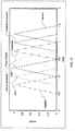
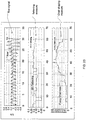
- FIG. 1 shows an example of such a patient first breathing normally at 102, then experiencing airway collapse at 104 and, despite more negative excursions in oesophageal pressure (a measure of breathing effort), not managing to increase tidal volume or flow-rate.
- the ResMed AutoSet algorithm monitors patient flow and raises pressure when it detects flow limitation or snore. Because apnoeas are normally preceded by periods of flow limitation (also called partial obstruction) or snoring, apnoeas are rarely encountered. As a backup measure, pressure is also raised if an apnoea is detected. In the absence of any measured flow disturbance, the pressure is allowed to decay slowly and hopefully an equilibrium pressure will be achieved that allows the patient to sleep arousal-free.
- the AutoSet algorithm responds proportionally and so a metric is used for each condition to which it responds. The metrics used are: a flattening index for flow-limitation, a calibrated RMS measure of sound averaged over an inspiration for snore and the length of any apnoea detected.
- a flattening index is a non-dimensional feature (e.g., a real number) calculated using a patient's inspiration waveform. It attempts to measure essentially how flat-topped the waveform is.
- a feature of flow limitation is that while the downstream pressure is sufficiently low to keep the tube collapsed the flow-rate will be more or less maintained at a constant value, regardless of changes to the driving pressure. In a patient with flow-limited breathing this equates to an inspiratory waveform with a flat top (i.e., a constant inspiratory flow-rate.)
- normal breathing can produce a flattening index of around 0.2 while a severely flattened waveform can produce a flattening index of about 0.1 or less.
- a limit is typically established (e.g., 0.19 in some machines) and the pressure is raised in proportion to how far the flattening index is below the threshold.
- a typical pressure setting algorithm may also use a five breath point-wise moving average. A possible disadvantage of the five breath average is that it slows down the detection of flow-limitation because five abnormal breaths need to be averaged before flattening may fall to its final nadir.
- heuristic weightings can be applied to the threshold at which flattening will cause the pressure to rise, such that greater reductions in flattening are required: as the leak increases, as the therapy pressure rises and as evidence of valve-like breathing increases. These heuristics serve to prevent potential pressure runaway in the face of degraded information (flow signal).
- M-shaped breaths may be rare, it may still be desirable to develop further methods and devices for detecting flow-limitation and/or improve existing methods and devices.
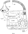
- the present technology involves a pressure delivery and/or flow limitation detection device that may include a flow generator such as a servo-controlled blower 402.
- the device will typically also include a patient interface such as a mask 406 and an air delivery conduit 408 to carry a flow of air or breathable gas to and/or from a patient.
- the blower 402 may be coupled with the air delivery conduit 408 and the mask 406. Exhaust gas can be vented via exhaust 413.
- a flow sensor 404f and/or pressure sensor 404p may also be utilized.
- mask flow may be measured using a pneumotachograph and differential pressure transducer or similar device such as one employing a bundle of tubes or ducts to derive a flow signal F(t) .
- mask pressure may be measured at a pressure tap using a pressure transducer to derive a pressure signal P mask (t).
- the pressure sensor 404f and flow sensor 404p have only been shown symbolically in FIG. 4 since it is understood that other configurations and other devices may be implemented to measure flow and pressure.
- the flow F(t) and pressure P mask (t) signals may be sent to a controller or microprocessor 415 via one or more analog-to-digital (A/D) converters/samplers (not shown) to derive a pressure request signal P request (t).
- A/D analog-to-digital
- a flow signal f (t) and/or pressure signal P mask (t) may be estimated or calculated in relation to the blower motor by monitoring current (I) supplied to the motor, the speed (S) and/or revolutions (w) of the motor with or without the provision of flow and pressure sensors as described above.
- the blower motor speed may be held generally constant and pressure changes in the mask may be implemented by controlling an opening of a servo-valve that may variably divert/vent or deliver airflow to the mask.
- other types of patient interface may be used in place of the mask and the flow and/or pressure sensors may measure flow and pressure in alternative locations with respect to the patient interface.
- the controller or processor 415 is configured and adapted to implement the methodology or algorithms described in more detail herein and may include integrated chips, a memory and/or other control instruction, data or information storage medium.
- programmed instructions with the control methodology may be coded on integrated chips in the memory of the device or such instructions may be loaded as software or firmware using an appropriate medium.
- the apparatus can be used for many different pressure treatment therapies by adjusting the pressure delivery equation that is used to set the speed of the blower or to manipulate the venting with the release valve and may be based on detection methodologies involved in the pressure delivery equation as illustrated in the example embodiments detailed herein. Alternatively, they may be implemented in a device without the pressure treatment components such that the device may be used to diagnose, detect and/or quantify the existence of flow limitation.
- fuzzy logic is a way for transforming ideas for system behavior into computer code that is based on real numbers for the parameters of a control system.
- the problem at hand is basically one of statistical pattern recognition and may be implemented using other techniques such as the alternatives discussed in more detail herein. Therefore, while the following technology is presented in terms of a fuzzy logic control system, it is understood that there are other ways of implementing the methodologies into a control system based on the desired control inputs and the exemplary output functions.
- an embodiment of the control system of the present technology can be implemented according to the following general approach using a partial obstruction or flow limitation measure such as a Fuzzy Flow-Limitation (FFL) measure.
- FFL Fuzzy Flow-Limitation
- the flow limitation measure FFL uses multiple feature pattern recognition to improve the sensitivity and specificity of the algorithm's response to flow-limitation (or more properly: partial upper-airway obstruction).
- the general approach with the flow limitation measure FFL may include some or all of the following steps:
- an example system maps input parameters that vary widely in range to variables that can be readily interpreted with fuzzy logic principles.
- a shape index such as a flattening index may be mapped to the fuzzy variables such as HIGH_FLATTENING, NORMAL_FLATTENING and LOW_FLATTENING, etc.
- Each of these variables would take a value between zero and one, depending on the value of the flattening index as determined by mathematical functions associated with the variables and based on the input data associated with a flattening determination such as respiratory airflow.
- other fuzzy variables can map a ventilation measure such as HIGH_VENTLATION, NORMAL_VENTILATION and LOW_VENTILATION, etc., based on appropriate mathematical functions and input data associated with determining ventilation.
- Still other fuzzy variables can also map a respiratory duty cycle measure (e.g., a ratio of time of inspiration (T i ) to the total time of a breathing cycle (T tot )) such as T i -on-T tot _LOW, T i -on-T tot _NORMAL, or T i -on-T tot _HIGH, etc.
- a respiratory duty cycle measure e.g., a ratio of time of inspiration (T i ) to the total time of a breathing cycle (T tot )
- T i -on-T tot _LOW e.g., a ratio of time of inspiration (T i ) to the total time of a breathing cycle (T tot )
- T i -on-T tot _LOW e.g., T i -on-T tot _LOW, T i -on-T tot _NORMAL, or T i -on-T tot _HI
- the de-fuzzified output which can be used as a flow limitation measure, can be implemented to range between zero (no flow-limitation) and one (severe). With such a system, the input space can be classified in a non-linear sense using readily interpretable rules without any loss of real-number precision.
- the measure can be implemented proportionally to derive a response pressure or flow control setting well suited to treat the condition detected with the measure.
- the measure may be more directly implemented in the setting of a respiratory treatment apparatus or determining of a treatment setting for such a device.
- the obstruction measure may serve as a proportional function that may be directly applied to a pressure adjustment quantity or flow rate adjustment quantity (e.g., measure * adjustment quantity). The resultant adjustment quantity could then be applied to a treatment setting of a respiratory treatment apparatus.
- an "FFL" measure may be implemented to serve as such a proportional treatment setting function.
- flow limitation may be detected and/or quantized by a method that includes (a) determining a shape index indicative of a pattern of flow limitation from the measure of respiratory flow shown in step 502; (b) determining a ventilation measure or a breath duty cycle measure from the measure of respiratory flow shown in step 504; and (c) deriving a flow limitation measure as a function of the determined shape index and either or both of the determined ventilation measure or the determined breathing cycle measure shown in step 506.
- a method that includes (a) determining a shape index indicative of a pattern of flow limitation from the measure of respiratory flow shown in step 502; (b) determining a ventilation measure or a breath duty cycle measure from the measure of respiratory flow shown in step 504; and (c) deriving a flow limitation measure as a function of the determined shape index and either or both of the determined ventilation measure or the determined breathing cycle measure shown in step 506.
- increases to treat flow limitation may be based on a condition such that a pressure change can occur if it is determined that both (a) a shape index is indicative of the presence of an M shape breath or flattened breath in the respiratory airflow and (b) the ventilation measure is decreasing sufficiently to be indicative of less than normal ventilation.
- Additional increases to treat flow limitation may be based on another condition such that a pressure change can occur if it is determined that both (a) the shape index is indicative of the presence of an M shape breath in the respiratory airflow and (b) an increase of the duty cycle measure is detected.
- the system may be characterized by the use of a plurality of input features (e.g., 4) for deriving the flow limitation measure FFL.
- the input features may include (1) a single-breath flattening (SBF) shape index, (2) an M shape index (MS), (3) a ventilation measure such as a ventilation-ratio (VR) and/or (4) a respiratory duty cycle measure such as the ratio of inspiratory time to the total breath time (T i -on-T tot ).
- An embodiment of a shape index implemented as a single breath flattening index SBF may be calculated similar to the approach disclosed in United States Patent No. 5,704,345 except that it is preferably performed without using a five-breath moving-average.
- the details of an implementation of a single breath flattening shape index determination are disclosed in section A herein.
- An exemplary implementation of a determination of an M-shape shape index is described in section B herein.
- the illustrated calculation of the M-shape feature can vary in the range from zero (i.e., the inspiratory flow waveform is not M-shaped) to one (i.e., the inspiratory flow waveform is definitively M-shaped).
- the M-shape index may optionally be augmented by another shape index such as a simple "chair-shape" index.
- An exemplary determination of the chair-shape index (e.g., Fuzzy "Chairness”) is also detailed in section B.
- An embodiment of a determination of a suitable ventilation measure may be based on a tidal volume calculation.
- the ventilation measure may be a ratio including a current tidal volume and a prior tidal volume such that the measure can be indicative of changes in ventilation or tidal volume.
- the measure may be a ventilation ratio VR that can be calculated as follows:
- the VR will oscillate over a small range of about one. In the event of severe upper-airway obstruction, it will descend to values much less than one and can descend to zero for total obstruction. Big breaths (recovery breaths on arousal) will have a VR much greater than one (e.g., 1.5-2). Further details for a calculation of the particular ventilation ratio VR are included in Section G herein.
- the system can optionally utilize a respiratory duty cycle measure in the derivation of flow limit measure FFL.
- the measure may be based on a ratio of a current and prior duty cycle so that it can be indicative of changes in the respiratory duty cycle.
- Exemplary details for the calculation of a respiratory duty cycle ratio TTR are further described in Section G herein.
- a suitable breath duty cycle measure can be based on the calculation of a T i -on-T tot variable. The chosen variable has the (implausible) limits of zero (no inspiration) and one (no expiration).
- T i -on-T tot can vary from patient to patient
- a ratio of T i -on-T tot to its recent mean value is calculated which has been designated herein a T i -on-T tot ratio.
- the recent mean value of T i -on-T tot can be calculated by feeding each T i -on-T tot value calculated into a simple low-pass filter. When T i -on-T tot is increasing relative to recent history, the TTR will exceed one.
- T i -on-T tot has values around 0.4 while TTR will be one ordinarily and greater than one when patients are trying to "compensate", i.e ., increase their tidal volume in the face of an obstructed upper airway.
- the shape index SBF can be mapped into, for example, six fuzzy variables: B_LOW_FLATTENING, EXTRA_LOW_FLATTENING, VERY_LOW_FLATTENING, LOW_FLATTENING, NORMAL_FLATTENING and HIGH_FLATTENING.
- variable B_LOW_FLATTENING would result in a value of 1.0 and a value of zero for all of the other fuzzy variables in the graph of FIG. 6 .
- Other suitable functions and variables may be selected as desired.
- example membership functions and variables based on the computation of the M-shape shape index are shown in FIG. 7 .
- This graph presents suitable functions for LOW_M-SHAPE, NORMAL_M-SHAPE, HIGH_M-SHAPE, VERY_HIGH_M-SHAPE and B_HIGH_M-SHAPE.
- Example membership functions and variables based on the computation of the ventilation ratio index are shown in FIG. 8 .
- This graph presents suitable functions for VERY_LOW_VENTILATION, LOW_VENTILATION, NORMAL_VENTILATION, HIGH_VENTILATION and VERY_HIGH__VENTILATION.
- example membership functions and variables based on the computation of the breath duty cycle ratio are shown in FIG. 9 .
- This graph presents suitable functions for T i -on-T tot _LOW, T i -on-T tot _NORMAL, T i -on-T tot _HIGH and T i -on-T tot _VERY_HIGH and T i -on-T tot _EXTRA_HIGH.
- a system may then apply or evaluate rules based on combinations of the variables in the derivation of the flow limitation measure FFL.
- Table A summarizes a set of fuzzy rules that may be applied with the fuzzy variables associated with the single breath flattening shape index and the ventilation ratio measure.
- the rule in bold (“M to M", i.e ., Mild to Moderate) in the "Very High” column with respect to flattening shape index's fuzzy variables and the "low” row with respect to the ventilation ratio measure's fuzzy variable represents the fuzzy rule: if (VERY_HIGH_FLATTENING AND LOW_VENTILATION) then FFL is "Mild-to-Moderate".
- tidal volume e.g ., the ventilation ratio
- a patient maintains his or her tidal volume by increasing the duty cycle, i.e . by stretching the inspiration time as a percentage of the overall inspiration-expiration time.
- This trend can be measured or determined using a duty cycle measure (e.g ., TTR) which in this embodiment will increase above one as the inspiration time lengthens.
- the system may further combine flattening shape index information with a breath duty cycle measure (e.g., TTR) in a similar manner as it had been combined with a ventilation measure (e.g ., VR) using the rules represented by the following table B.
- TTR breath duty cycle measure
- VR ventilation measure
- table B represents fuzzy rules as well as a corresponding natural language description of flow obstruction based on the measure of breath duty cycle and the flattening shape index.
- the rule in bold (“M to S”, i.e ., Moderate to Severe) in the "Extra High” column and the "Very High” row is the fuzzy rule: if (EXTRA_HIGH_FLATTENING AND T i -on-T tot _VERY_HIGH) then FFL is Moderate-to-Severe.
- the flow limitation measure may also be derived by using both M-shaping and/or Augmented M-shaping detection indices and either or both of the ventilation or breath duty cycle measures. Aspects of this derivation are illustrated in tables C and D. TABLE C M-Shaping or Augmented M-Shaping and Ventilation Measure M-shaping or Aug.
- Table C represents rules like the rules of the prior charts except that they relate to the fuzzy variables based on the M-shaping shape index and/or the chair-shape index.
- the rules in part are intended to prevent a response to a detected M-shape breathing pattern where the patient has a normal or above average ventilation.
- the flow limitation measure is derived so that the system will not respond to certain types of arousal breaths and "behavioral" M-shape breathing patterns such as those that can occur during REM sleep but are not indicative of a current flow limitation.
- the rule represented by the entry in the top row of the last column of table C indicates that the output function is "zero" for a bad "B High” M-shape index related measure when there is a good ventilation measure (e.g ., "Very High”).
- Table D represents particular fuzzy rules as well as a corresponding natural language description of flow obstruction or measures of flow limitation derived from the measure of breath duty cycle and the M-shaping and/or the augmented M-shaping determinations.
- the matrix "combines" the M-shape information with the T i -on-T tot Ratio (rather than ventilation ratio).
- the matrix may be considered to relate to breaths that exhibit M-ness, or a degree of the existence of an M-shape pattern, in the presence of a trend of increasing breath duty cycle. This combination identifies flow limitation in breaths where the patient's ventilation is about "normal” and the patient is "compensating" by taking longer inspirations.
- Results of the rules applied based on tables A, B, C and D may thereafter be applied to output functions.
- FIG. 10 shows suitable fuzzy output membership functions that may be applied with the results.
- the output membership functions include NEGATIVE, ZERO, MILD, MILD_TO_MODERATE, MODERATE, MODERATE_TO_SEVERE and SEVERE.
- a centroid method or other such de-fuzzification operation may be performed.
- the crisp value of the output variable is determined by finding a value associated with the center of gravity of the values for the output functions.
- the flow limitation measure may be derived so as to avoid treatment of other potential detected conditions.
- an arousal breath may be flat in shape or M-shaped, thus potentially indicative of a flow limitation based on a determination with the shape indices, but the breath actually may be of a stretched inspiratory time and thus not indicative of actual flow limitation in the patient.
- the flow limitation measure may be derived so as not to treat such a breath as flow limited.
- One manner of doing so is to modify the fuzzy outputs of the fuzzy rules from tables A, B, C, and D so as to adjust the combinations that use the breath duty cycle measure TTR with the function illustrated in FIG. 12 .
- the fuzzy outputs resulting from the rules based on a combination of the duty cycle measure TTR are multiplied by the output of the function of FIG. 12 before defuzzification.
- the ventilation ratio measure VR increases, which indicates an increasing likelihood of an arousal breath, the output of the rules of tables B and D are progressively de-weighted according to the example function of FIG. 12 and by the multiplication operation until the ventilation ratio measure VR approaches 1.5. At that point, the result of the multiplication operation will render the output of the affected rules to be zero.
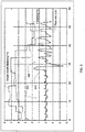
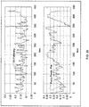
- FIG. 13 provides a graphic comparison between a traditional flattening index and a derived flow limitation measure FFL in accordance with steps of the above summary.
- the index and measure are based on the same flow signal shown in the bottom trace.
- the bottom trace flow signal includes a sequence of obstructed breaths ending in an arousal followed by some reasonably normal recovery breaths, and then some more obstruction.
- the breaths are initially "flat” and then progressively more M-shaped.
- the traditional flattening index initially falls then rises and finally falls sharply during the recovery breaths.
- the flow limitation measure FFL of the middle trace rises steadily both due to flattening and the M-ness shape of the breaths and then falls to zero when breathing in the flow signal becomes more normal.
- the flow limitation measure may also be implemented in the control of a pressure treatment device.
- the measure may be implemented with any one or more of the following as follows:
- the flow limitation measure FFL may optionally be implemented as part of a respiratory effort related arousal (RERA) detector.
- RERA respiratory effort related arousal
- a RERA detector may be based on a real flow signal derived from a flow-generator. For example, a flow limitation measure by any of the methods previously described may be determined based on a flow signal. A measure of arousal may then be derived as a function of the flow limitation measure and a further function of a measure of an increase in ventilation.
- the RERA detector may be based on the following methodology: if there has been flow limitation recently (e.g., FFL is greater than (>) 0) followed by a ventilation step change (e.g., a big breath) then a RERA is detected.
- FFL flow limitation
- a ventilation step change e.g., a big breath
- the measure is implemented as a continuous variable so that adjustments to a threshold based on experimental data can be made.
- This may be an alternative to a Boolean threshold on each input parameter which results in lost information).
- the following algorithm may be used:
- the bottom signal represents a continuous RERA Detector measure based on this methodology.
- the bottom trace show a detection of a respiratory effort related arousals based on the arousals of the top trace showing a flow signal.
- the RERA Detector may be further implemented as part of a respiratory disturbance index.
- RERAs could be reported by a therapy device as an indication of the effectiveness of the therapy.
- the RERA index described herein could be used as input into a therapy algorithm.
- the RERA index could be determined over a certain time frame, such as per hour, and the result may be used in an "outer loop controller" to set the threshold (or gain) for flow-limitation indices raising pressure.
- An example of an outer loop controller is described in WO 2005/051470 ( PCT/AU2004/001652 ) assigned to ResMed Ltd.
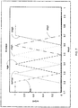
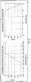
- a ratio of peak to mean expiratory flow may be used as another type of index of sleep-wake-arousal detection.
- the ratio of peak expiratory flow to mean expiratory flow may be part of the sleep-wake/arousal detection.
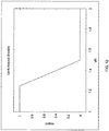
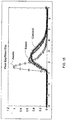
- FIG. 15 includes a histogram comparing awake normals with two sleep datasets. Awake breaths tend to be "flatter", i.e ., the peak is closer in value to the mean. By comparing a threshold, such as 0.5, with the ratio, a RERA may be considered to be detected.
- the flow signal that is used to calculate flattening may be called (amongst other things) "patient flow”.
- This flow signal can be the result of filtering a raw flow signal with a filter such as a "10 Hz" filter although filter types may vary.
- the filter preferably reduces unwanted signal content such as that caused by turbulent flow and snore.
- the filter may also attenuate cardiogenic content slightly.
- the filter is a trade off between accurately detecting zero crossing points on the one hand and rejecting unwanted signal on the other. For example, if the filter were made more aggressive to reject all cardiogenic oscillations, breath detection could be rendered inaccurate. However, once breath detection is complete, further filtering may occur as desired.
- a filtered single breath flattening may be determined by the following:
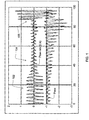
- FIG. 16 shows two superimposed flow signals recording a sequence of obstructive breaths where the normal calculation of flattening might be corrupted by (in this case) low-frequency snore.
- One of the signals has been filtered (and delay compensated) such that the snore is not evident.
- the filtered signal will give appropriately lower values of flattening calculated on a signal breath basis when compared to a calculation based on the other signal in which the snore is evident.
- the last breath has traditional flattening values calculated as: 0.21 (based on the unfiltered signal) and 0.13 (based on the filtered signal).
- 0.21 based on the unfiltered signal
- 0.13 based on the filtered signal.
- the latter value is indicative of a required pressure rise while the former is not indicative of a pressure rise.
- a traditional five-breath point-wise averaging may also achieve this filtered result but at the expense of significant response delay.
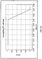
- a typical (and non-computationally-intensive) filter to use is a boxcar FIR filter.
- a boxcar filter of length 12 has a response illustrated in FIG. 17 at a sampling frequency of 50 Hz.
- the impulse response of the filter is not critical if there is a concern primarily with the signal of the middle half of each inspiration.
- a suitable method for determining an obstruction measure such as an M-Shape index may be accomplished with the following algorithm.
- the index detects the presence of "M" shaped breath patterns. Such an index may also be commonly considered an indicator of "u” shaped breath patterns.
- the obstruction measure may also be augmented or modified by an additional obstruction measure.
- an index of obstruction may be derived as a function of a first obstruction measure, such as an "M" shape index, and a second obstruction measure, such as an "h" or chair shape index.
- B 1 sin ⁇ t
- B 2 sin 3 ⁇ t
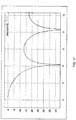
- FIG. 18 plots suitable functions to serve as basis vectors B1 & B2.
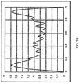
- the flow signal for a typical M-shaped breath is plotted in the graph of FIG. 19 . Based on the above methodology, calculations for the plotted breath are as follows:
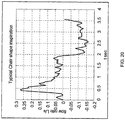
- an M-shape breath may be augmented by a simple chair shaping. This is illustrated in FIG. 20 , which plots a flow signal having flow limitation that produces the augmented shape.
- Such inspirations can be characterized by two features: 1) a high ratio of peak to mean inspiratory flow and 2) a normalized peak location close to either 0 (a left-backed chair as illustrated in FIG. 20 ) or 1 (a right-backed chair not shown)).
- Fuzzy _ Chairness Fuzzy ⁇ AND Fuzzy _ Peak _ to _ Mean , Fuzzy _ Peak _ Loc .
- the inspiration of FIG. 20 has a fuzzy chairness of 0.82.
- the scaling of the fuzzy chairness feature is such that it can be fuzzy OR-ed directly with the M-shape feature for a combined shape index.
- a fuzzy chairness of approximately greater than 0.3 implies flow-limitation. Fuzzy chairness can be described in English as: "if the ratio of the peak of inspiration to the mean of inspiration is high AND the location of peak inspiratory flow is near the beginning or end of inspiration THEN the inspiration is chair shaped.”
- FIG. 23 a typical flow sequence is shown where the inspiratory shape is initially flat such that an SBF index is approximately less than 0.2. However, the shape turns chair-shaped such that the SBF index (SB flattening) is approximately greater than 0.2 but the Fuzzy Chairness or the chair-shape index is approximately greater than 0.3.
- FIG. 25 shows why the FFL flow-limitation measure did not cause the pressure to rise in this sequence.
- the patient is maintaining their tidal volume (e.g., VR approximately 1) without stretching their inspiratory time as a function of total breath time (e.g., TTR approximately 1).
- tidal volume e.g., VR approximately 1
- TTR approximately 1 total breath time
- a first obstruction measure may be derived from filtering a second obstruction measure such as a flattening index.
- a second obstruction measure such as a flattening index.
- the historic value may be reset if normal breathing is achieved (e.g., no obstruction) so that the history or filtered obstruction measure is an indicator of continuous or persistent past obstruction.
- fuzzy persistent flattening For example, a "fuzzy persistent flattening" may be implemented. As the name suggests, this fuzzy persistent flattening measure responds essentially to consistently low values of the flattening index. The measure is also implemented to respond slowly relative to the FFL flow limitation measure so that it does not interfere with the flow limitation measure FFL and over-treat the patient.
- the system preferably filters a single-breath flattening index in the following way:
- a breath detection algorithm may be used to get the current respiration rate (RR, breaths per minute) which can be determined as an average of the five most recent breaths detected.
- RR current respiration rate
- the value to be filtered is a (filtered) single-breath flattening index.
- the system may optionally "head-limit" the incoming values.
- HVF head limited flattening
- Another feature of the filter is that a different gain is used for inputs that are less then the current value of PF than for values that are greater then the current value of PF as follows:
- FIG. 26 illustrates the response of FPF to the same sequence of breaths shown in FIG. 24 .
- FIG. 27 illustrates a function for a de-weighting factor that can be multiplied by a flow limitation measure (e.g., FFL). Breaths which are determined to be unrealistically long (T i > 2.5 sec) or short (T i ⁇ 0.7 sec) are progressively de-weighted.
- FFL flow limitation measure
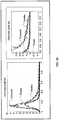
- FIG. 28 shows a typical sequence of snores captured while a patient was asleep.
- the upper panel shows respiratory flow-rate
- the middle panel instantaneous snore (e.g., a measure of the acoustical power in the frequency range of interest)
- the lower panel shows three snore indices.
- the calibrated inspiratory snore index (labeled "snore index" in FIG. 28 ) is calculated as follows:
- This technique is reliable when used to treat snore by raising the mask pressure in proportion to the measured snore index.
- the technique requires that calibration constants be measured for each flow-generator-mask combination and stored in non-volatile memory of the apparatus. Such calibrations are time-consuming and hence costly and may be subject to change with time.
- delta snore is calculated as the difference between the mean of the instantaneous snore signal during inspiration minus the mean of the instantaneous snore signal during expiration. This is in essence a self calibration measure that assumes the background noise sources will vary little between inspiration and expiration. However, this is not always true.
- an inspiratory snore entropy method is implemented.
- this measure of obstruction is determined by filtering a measure of respiratory flow in a frequency range associated with snoring (e.g., 30 to 300 Hz). The magnitude of the power or energy of the filtered signal in the frequency range is then examined as a function of time to assess whether the power signal is indicative of some inspiratory shape or whether it is simply random noise.
- a Shannon entropy function may be used. If the function indicates that the energy signal is merely random information or noise, then the snore index may be adjusted or de-weighted since real snoring may not be occurring.
- Such a method uses the information contained in the instantaneous snore signal during inspiration.
- Such an index also does not require calibration,
- the obstruction measure may be calculated as follows:
- Both delta snore and snore entropy are plotted in the lower panel of FIG. 28 .
- a judicious combination of both delta snore and snore entropy was found to correctly classify snores in nearly all cases.
- the graph of FIG. 29 shows one such arrangement.
- the classifier denoted by the plotted line can be stated as: "if delta snore is positive then treat, else if delta snore is negative then require progressively higher snore entropy with negative delta snore to treat.”
- trim_leading_pause This function was designed to trim the front of the currently framed inspiration so as to remove any dangling expiratory pause from the previous expiration by detecting a peak and extrapolating backwards to an appropriate zero crossing that would be indicative of a beginning of inpsiration. This function can fail on M-shaped breaths as illustrated in FIG. 30.
- FIG. 30 shows an incorrect trim (on the second peak) and a correct trim (on the leading peak).
- the method can be modified such that it sets a boundary on where the peak of inspiration can be found that can assist with M-shape breaths.
- the beginning of inspiration is determined by extrapolation from a first peak rather than a second peak of the inspiratory portion of the breath based on a boundary within inspiration.
- this boundary may be calculated as follows:
- the plot of FIG. 31 shows a sequence of flow-limited breathing in a flow signal with a number of breaths similar to that shown in FIG. 30 .
- the top panel of FIG. 31 shows flow-rate plotted vs. time, the bottom panel shows the calculated inspiratory time (T i ) with trim_leading_pause applied.
- T i inspiratory time
- trim_leading_pause applied.
- a ventilation measure such as the Ventilation Ratio (VR) may be determined as the ratio of the current breath-wise ventilation to the recent medium-term ventilation (V 3 ).
- medium-term can be a ventilation measure filtered using a filter with a three minute time constant ⁇ .
- the filter used may be a simple first-order auto-regressive filter. Because the time constant of the filter is reasonably large, the filter will take some time to rise from zero. The measure will thus transition slowly between the reasonable ventilation value and the filter output during the time [t 0 :3 ⁇ ].
- VR can be calculated as follows:
- a duty cycle measure may be implemented for deriving a measure of obstruction as previously discussed. For example, from a measure of respiratory flow second ratio of duration of an inspiratory portion of a respiration cycle to duration of the respiration cycle as a function of the measure of respiratory flow. Similarly, a second such measure may be determined which may be subsequent in time to the first measure. The measure of obstruction may then be derived as a function of the first ratio and the second ratio.
- a suitable duty cycle measure such as the T i -on-T tot ratio (TTR) may be determined as the ratio of the current (breath) T i -on-T tot value to the recent medium-term T i -on-T tot value.
- Medium-term can be determined by filtering with a five minute time constant or other suitable time constant.
- the filter can be a simple first-order auto-regressive filter. TTR may be calculated as follows:
- the functions graphed in FIGs. 32 and 33 can be used to de-weight the effect of a measure of flow limitation (e.g., FFL) or a measure of snore.
- the function can be applied to increase the threshold of the measures (e.g., FFL or snore) that needs to be exceeded for a pressure rise to occur.
- a de-weighting function may involve a valve-like leak ratio.
- a valve-like leak measure can be calculated in a customary way such that its value varies between 0 and 5.
- the system may be implemented to de-weight a valve-like leak value to the extent that there is no absolute leak present. So the algorithm for determining de-weighting due to valve-like leak is as follows:
- the de-weighting of the flow limitation measure (e.g., FFL) based on leak can be done using the function shown in the graph of FIG. 33 .
- FFL flow limitation measure
- L/s leak
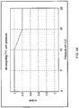
- the de-weighting of the flow limitation measure by pressure may also be accomplished using a function such as the example graphed in FIG. 34 .
- a function such as the example graphed in FIG. 34 .
- the output is 0.8.
- the output may then be multiplied by the measure of flow limitation.
- Jamming is a measure such as the fuzzy extent to which the current inspiration or expiration have been going on for too long.
- Jamming may be determined by the methodology described in U.S. Patent No. 6,484,719 .
- High jamming is indicative of a transient change in the leak, for example, when a patient opens there mouth or when they shift in bed and change their mask position on the face.
- the flow estimate is not accurate and that the leak constant is being reduced to help improve the flow estimate. While this is happening it is prudent to prevent pressure rises until things have calmed down. This can be accomplished by the example function of FIG. 35 .
- jamming reaches 0.25 the system can begin de-weighting until the measure is completely de-weighted at a jamming level of 0.5.
- the output of the function may be multiplied by the measure of flow limitation to effect the de-weighting.
- a measure of snore may be de-weighted based on various conditions of the system. For example, a value of snore may be de-weighted by the function of pressure illustrated in FIG. 36 . This makes the system less sensitive to the snore measure for purposes of generating a pressure rise. Thus, the value of snore required for a rise in treatment pressure increases with increasing pressure.
- the inspiratory snore index can also be de-weighted by a measure of ventilation such as a measure of a "big-breath.” Big breaths often induce noise simply due to the high peak flows achieved.
- ventilation may be utilized to generate a de-weighting output factor depending on whether the ventilation measure is considered to be a big breath.
- a ventilation measure such as the ventilation ratio (VR) may be used as a measure of big breaths. Values of VR greater than (>) 1 may be taken as indicating breaths that are large compared to the medium term ventilation.
- the system may refrain from de-weighting any measure of snore and for values of VR greater then (>) 1.5 the system may completely de-weight the effect of snore.
- the output de-weighting factor may decrease linearly from one to zero.
- a normalized expiratory peak location is a good indicator of a transition from sleep or obstructed sleep flow waveforms to waveforms indicative of wake, arousal or other unnatural, out-of-the-ordinary or unrecognizable events such as severe mouth leak.
- an apparatus of the present technology may implement a measure of arousal based on a peak expiratory flow. For example, depending on the location of a peak expiratory flow or normalized peak expiratory flow within an expiratory portion of a respiratory cycle, an arousal may be assessed.
- the time of the expiratory portion may be defined by ranges and the occurrence of the peak within the defined ranges defines an index that is indicative of arousal. The index may be indicative of arousal if the expiratory peak occurs in a latter time portion or range of the expiratory portion of the respiratory cycle.
- the graph in the right-hand side of FIG. 38 shows that awake breathers have far more breaths with values greater than (>) 0.5 than the asleep patients who have few.
- a system can be implemented with a de-weighting function for a flow limitation measure based out-of-the-ordinary, unnatural or unexpected events with respect to sleep.
- a suitable function based on a calculated or determined normalized inspiratory peak location value is illustrated in the graph of FIG. 39 . The function is used to increase the strength of the flow-limitation measure required to cause a rise in treatment pressure as the breath becomes more unnatural, out-of-the-ordinary or unrecognizable (e.g., weird).
- the desired flow limitation detection and/or treatment system can be based on other techniques for pattern recognition such as taking each inspiration and interpolating it over a grid of as many points as required to maintain important frequency information. For example, each inspiration may be interpolated over a grid of 65 points.
- a large set of training data may be developed with the different types of obstructed waveforms that can be recorded based on clinical evaluations.
- the waveforms may be pre-classified to categories such as mild, moderate and severe or other such category as desired.
- the 65 points of each waveform may then be input into a classifier for training (such as a neural network, support vector machine or other) and using an appropriate algorithm, such as one based on a genetic algorithm, arbitrary boundaries can be defined in the 65 dimensional space between the various categories of obstruction.
- a classifier for training such as a neural network, support vector machine or other
- an appropriate algorithm such as one based on a genetic algorithm, arbitrary boundaries can be defined in the 65 dimensional space between the various categories of obstruction.
- Such a system would then be capable of classifying any inspiratory waveform measured in a patient against the metric of the classifier and used in a control system for treatment of the patient.
Description
- The presented technology relates to methods and apparatus for the detection, diagnosis and/or treatment of respiratory conditions such as the conditions related to sleep apnea hypopnea syndrome (OSAHS) or obstructive sleep apnea (OSA).
- As described by Sullivan & Lynch in
U.S. Patent No. 5,199,424, issued on April 06, 1993 , the application of continuous positive airway pressure (CPAP) has been used as a means of treating the occurrence of obstructive sleep apnea. The patient is connected to a positive pressure air supply by means of a nose mask or nasal prongs. The air supply breathed by the patient is slightly greater than atmospheric pressure. It has been found that the application of continuous positive airway pressure provides what can be described as a "pneumatic splint", supporting and stabilizing the upper airway and thus eliminating the occurrence of upper airway occlusions. It is effective in eliminating both snoring and obstructive sleep apnea and in many cases, is effective in treating central and mixed apnea. - In
U.S. Patent No. 5,549,106 to Gruenke, issued on August 27, 1996 , an apparatus is disclosed that is intended for facilitating the respiration of a patient for treating mixed and obstructive sleep apnea. The device increases nasal air pressure delivered to the patient's respiratory passages just prior to inhalation and by subsequently decreasing the pressure to ease exhalation effort. - In
U.S. Patent No. 5,245,995 Sullivan discusses how snoring and abnormal breathing patterns can be detected by inspiration and expiration pressure measurements while sleeping, thereby leading to early indication of preobstructive episodes or other forms of breathing disorder. Particularly, patterns of respiratory parameters are monitored, and CPAP pressure is raised on the detection of pre-defined patterns to provide increased airway pressure to, ideally, subvert the occurrence of the obstructive episodes and the other forms of breathing disorder. - As described by Berthon-Jones in
U.S. Patent No. 5,704,345, issued on January 6, 1998 , various techniques are known for sensing and detecting abnormal breathing patterns indicative of obstructed breathing: Berthon-Jones describes methods based on detecting events such as apnea, snoring, and respiratory flow flattening. Treatment pressure may be automatically adjusted in response to the detected conditions. - As described by Wickham in International Patent Application
PCT/AU01/01948 WO0218002 - Other methods for detecting obstruction have also been used. For example, in
U.S. Patent Nos. 5,490,502 and5,803,066, Rapoport et al. discloses a method and apparatus for optimizing the controlled positive pressure to minimize the flow of air from a flow generator while attempting to ensure that flow limitation in the patient's airway does not occur. Controlled positive pressure to the airway of a patient is adjusted by detecting flow limitation from the shape of an inspiratory flow waveform. The pressure setting is raised, lowered or maintained depending on whether flow limitation has been detected and on the previous actions taken by the system. - In
U.S. Patent No. 5,645,053, Remmers describes a system for automatically and continuously regulating the level of nasal pressure to an optimal value during OSA (Obstructive Sleep Apnea) treatment. Parameters related to the shape of a time profile of inspiratory flow are determined including a degree of roundness and flatness of the inspiratory profile. OSA therapy is then implemented by automatically re-evaluating an applied pressure and continually searching for a minimum pressure required to adequately distend a patient's pharyngeal airway. - Despite the availability of such devices for treating OSA, some sleep obstructive events may still go untreated with the use of some devices. Thus, new methods of automated detection and treatment of obstructive events may be desirable.
US 2004/0123866 A1 relates to methods and apparatus for determining the occurrence of an apnea, patency and/or partial obstruction of the airway. -
US 6,099,481 A relates to a method of sampling one or more respiratory profile characteristics and monitoring a variety of respiratory profile parameters. -
US 2006/0060198 A1 relates to a method and system of scoring sleep disordered breathing. -
US 2005/0061319 A1 relates to an implantable device is used to monitor one or more conditions associated with an external breathing therapy delivered to the patient. -
WO 2006/079152 A1 relates to a method and system for detecting an ineffective effort of a patient being mechanically ventilated by a ventilator. -
WO 2006/133493 A1 relates to a method of acclimatizing a user to provide continuous positive airway pressure (CPAP) therapy, including operating a device for treating sleep disordered breathing (SDB) during successive treatment sessions. - Furthermore, reference is made to the following articles:
- MARCUS C L ET AL: "Response to inspiratory resistive loading during sleep in normal children and children with obstructive apnea", JOURNAL OF APPLIED PHYSIOL, AMERICAN PHYSIOLOGICAL SOCIETY, US, vol. 87, no. 4, 1 October 1999 (1999-10-01), pages 1448-1454, XP008121363, ISSN: 8750-7587;
- FREY U ET AL: "Analysis of the harmonic content of the tidal flow waveforms in infants", JOURNAL OF APPLIED PHYSIOL, AMERICAN PHYSIOLOGICAL SOCIETY, US, vol. 91, no. 4, 1 October 2001 (2001 -10-01), pages 1687-1693, XP008121362, ISSN: 8750-7587.
- The invention is defined in the independent claims. Further embodiments of the invention are set out in the dependent claims.
- In an aspect of the present technology, apparatus and methods are provided with improved automatic detection and/or automatic treatment of sleep disordered breathing or flow limitation.
- In another aspect of the present technology, improved detection and/or treatment of flow waveforms indicative of partial obstruction is provided.
- In still another aspect of the present technology, apparatus and methods are provided for a more rapid response to indications of partial obstruction or flow limitation.
- In still another aspect of the present technology, apparatus and methods are provided for qualifying a measure of flow limitation or partial obstruction, such as a flow limited waveform or shape index thereof, by a measured or detected secondary condition of the airway to more accurately detect obstructive events.
- Aspects of the present technology involve methods for detecting flow limitation that may include determining a measure of respiratory flow, determining a shape index indicative of a pattern of flow limitation from the measure of respiratory flow, determining a ventilation measure or a breath duty cycle measure from the measure of respiratory flow and deriving a flow limitation measure as a function of the determined shape index and either or both of the determined ventilation measure and the duty cycle measure.
- In certain embodiments, the shape index may be an index of flattening, an index of "M" shaping, an index of a chair shaping and/or roundness etc. or other index that may be indicative of a partial obstruction. The ventilation measure may be a tidal volume measure such as a ratio of a current tidal volume to a prior tidal volume. The breath duty cycle measure may be a ratio such as a ratio of a current breath inspiration time to breath cycle time ratio and a prior average breath inspiration time to breath cycle time ratio.
- The methods may be implemented by flow limitation detectors and/or by flow limitation pressure treatment devices. For example, the methods may be implemented to adjust treatment pressure of a pressure treatment device, such as by increasing pressure as a condition of the shape index being indicative of the presence of an M shape breath in the respiratory airflow and the ventilation measure decreasing sufficiently to be indicative of less than normal ventilation. Optionally, the treatment pressure value may be adjusted or increased as a condition of the shape index being indicative of the presence of an M shape breath in the respiratory airflow and an increase of the duty cycle measure.
- In one embodiment of the technology, an apparatus to detect flow limitation may include a patient interface to carry a flow of breathable gas, a flow sensor coupled with the patient interface to generate a flow signal representing flow of the breathable gas through the patient interface, and a controller coupled with the flow sensor to process the flow signal, where the controller is configured to control a method of detection to derive the flow limitation measure based on the shape index and either or both of the ventilation measure and the breath duty cycle measure. The apparatus may further include a flow generator coupled with the controller and the patient interface, so that the controller can be configured to calculate a pressure request as a function of the flow limitation measure, and set the flow generator in accordance with the pressure request such as the adjustments described herein.
- In one embodiment of the technology, a system for the detection of flow limitation may include an interface means to carry a flow of breathable gas, a flow measuring means coupled with the interface means for generating a flow signal representing flow of the breathable gas through the interface means, and a processing means coupled with the flow measuring means for processing the flow signal, where the processing means is configured for processing a method of detection to derive the flow limitation measure based on the shape index and either the ventilation measure or breath duty cycle measure. The system may further include a flow means, coupled with the processing means and the interface means, for generating a controlled flow of breathable gas through the interface means such that the processing means may be configured for calculating a pressure request as a function of the flow limitation measure, and setting the flow generator in accordance with the pressure request.
- In another embodiment, the technology may be an information-bearing medium having processor-readable information thereon, such that the processor-readable information can control an apparatus for detecting respiratory flow limitation. The processor-readable information may comprise control instructions for determining a measure of respiratory flow, determining a shape index indicative of a pattern of flow limitation from the measure of respiratory flow, determining a ventilation measure and/or breath duty cycle measure from the measure of respiratory flow, and deriving a flow limitation measure as a function of the determined shape index and either or both of the determined ventilation measure and breath duty cycle measure. The processor-readable information may further comprise instructions for calculating a pressure request as a function of the flow limitation measure and making adjustments to pressure as described herein.
- Another aspect of the present technology involves the generation of pressure or flow control information or signals that are derived proportionally as a function of a measure of flow limitation. For example, a controller or processor may be configured to control or determine a pressure setting or flow rate setting for a respiratory treatment device. Based on a measure of respiratory flow, an obstruction measure or a shape index representing a degree of obstruction or flow limitation may be determined or calculated by the apparatus. The apparatus may further optionally determine a ventilation measure representing a degree of change in ventilation from the measure of respiratory flow. The treatment pressure setting or flow rate setting may be derived by the apparatus as a proportional function of either or both of (1) the degree of obstruction or flow limitation and (2) the degree of change in ventilation.
- Further embodiments of the technology will be apparent from the following disclosure.
- The present technology is illustrated by way of example, and not by way of limitation, in the figures of the accompanying drawings, in which like reference numerals refer to similar elements including:
-
FIG. 1 shows air flow of a patient first breathing normally, then experiencing airway collapse and finally arousing; -
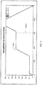
FIG. 2 shows a flattening index in reference to a patient experiencing obstruction indicated by an "M" shape breathing pattern; -
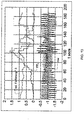
FIG. 3 shows flattening indices with and without multi-breath averaging in reference to a patient experiencing obstruction indicated by an "M" shape breathing pattern leading to a breathing pattern indicative of the patient's arousal from sleep; -
FIG. 4 shows example components of an apparatus for detection and/or treatment of flow limitation or partial obstruction; -
FIG. 5 illustrates suitable steps for a detection or treatment device in detecting flow limitation or partial obstruction; -
FIG. 6 shows example fuzzy membership functions for variables based on a single breath flattening shape index; -
FIG. 7 shows example fuzzy membership functions for variables based on an m-shape breath shape index; -
FIG. 8 shows example fuzzy membership functions for variables based on a ventilation ratio index; -
FIG. 9 shows example fuzzy membership functions for variables based on a breath duty cycle ratio; -
FIG. 10 shows example output membership functions for a flow limitation measurement; -
FIG. 11 shows and example de-fuzzification operation in the determination of a flow limitation or partial obstruction measure using a centroid method; -
FIG. 12 shows an example function for modifying the detection capability of the flow limitation or partial obstruction measure based on a measure of ventilation; -
FIG. 13 is a graphical comparison of a traditional flattening index with a calculated flow limitation measure FFL of the technology described herein determined from the same flow signal; -
FIG. 14 shows a flow signal derived from nasal flow and the output measure of a continuous RERA detector quantifying the likelihood of a respiratory arousal; -
FIG. 15 illustrates a ratio of peak to mean expiratory flow that may be an index of sleep-wake-arousal detection; -
FIG. 16 is two superimposed filtered and unfiltered flow signals recording a sequence of obstructive breaths in the presence of a low-frequency snore; -
FIG. 17 illustrates a response of an example FIR filter useful for filtering an airflow signal; -
FIG. 18 plots example functions to serve as basis vectors B1 & B2 for detecting M-shape breathing; -
FIG. 19 is a graph of the flow signal for a typical M-shaped breath; -
FIG. 20 is a graph of a flow signal showing an M-shape breath augmented by a simple chair shaping; -
FIG. 21 is a graph of a membership function for a variable based on a ratio of peak to mean inspiratory flow useful for detecting M-shape breaths having a chair shape; -
FIG. 22 is a graph of a membership function for a variable based on an inspiratory peak location useful for detecting M-shape breaths having a chair shape; -
FIG. 23 shows a graph of a flow signal, a graph of a determined measure of flatness and a graph of a determined measure of chair shaping; -
FIG. 24 shows a graph of a flow signal of a patient experiencing upper airway resistance with increasing breathing effort terminating in sleep arousal at t=420 and a corresponding graph of a single breath flattening index; -
FIG. 25 shows a graph of an example flow-limitation measure, ventilation measure and duty cycle measure based on the flow signal ofFIG. 24 ; -
FIG. 26 is a graph of a persistent obstruction measure or persistent flattening measure based on the sequence of breaths shown in the flow signal ofFIG. 24 ; -
FIG. 27 illustrates a function for a de-weighting factor that can be utilized for modification of a flow limitation measure; -
FIG. 28 presents a graph of a respiratory flow signal, a graph of an instantaneous snore signal and a graph of three snore indices; -
FIG. 29 shows a classifier for treating snore based on multiple snore indices; -
FIG. 30 is a graph of an M-shape breath with correct and incorrect trim results indicated thereon; -
FIG. 31 includes a graph of a flow signal verses time including m-shape breaths and a graph of determined inspiratory time made by two methods; -
FIG. 32 shows graphs of functions useful for de-weighting a measure of flow limitation depending on leak conditions; -
FIG. 33 is a further function useful for de-weighting the flow limitation measure or partial obstruction measure (e.g., FFL) based on leak conditions; -
FIG. 34 is a graph of a function suitable for de-weighting a flow limitation or partial obstruction measure by a level of mask pressure; -
FIG. 35 is a graph of a function suitable for de-weighting a flow limitation or partial obstruction measure by a measure of jamming; -
FIG. 36 is a graph of a function suitable for de-weighting a snore measure as a function of treatment pressure; -
FIG. 37 is a graph of a function suitable for de-weighting a snore measure based on a ventilation measure indicative of a big breath; -
FIG. 38 is a histogram of normalized expiratory peak location for various groups of patients; and -
FIG. 39 is a graph of a function of a de-weighting factor to be applied to a flow limitation or partial obstruction measure based on a normalized expiratory peak location value. - Patients with OSA have recurrent apnoeas or hypopnoeas during sleep that are only terminated by the patient arousing. These recurrent events cause sleep fragmentation and stimulation of the sympathetic nervous system. This can have severe consequences for the patient including day-time sleepiness (with the attendant possibility of motor-vehicle accidents), poor mentation, memory problems, depression and hypertension. Patients with OSA are also likely to snore loudly, thus also disturbing their partner's sleep. The best form of treatment for patients with OSA is constant positive airway pressure (CPAP) applied by a blower (compressor) via a connecting hose and mask. The positive pressure prevents collapse of the patient's airway during inspiration, thus preventing recurrent apnoeas or hypopnoeas and their sequelae.
- Ordinarily a patient will undergo two sleep studies where they are monitored using many sensors, the recording of which is known as a polysomnogram. The first study (without therapy) confirms the diagnosis of OSA, while the second is used to titrate the patient to the correct therapy pressure.
Pressure requirements vary throughout the night because of changes in position, posture and sleep state. The physician will recommend a pressure (the titration pressure) likely to cover any eventuality. An alternative to this is an automatic machine that adjusts the pressure to the patient's needs; this therapy is known as automatic positive airway pressure or APAP. An advantage of APAP therapy is that it is adaptable to pressure requirements that may change over many time scales. For example, pressure requirements change during the night with posture and sleep state, perhaps over the weekend with alcohol consumption, over months because of the beneficial effect of the therapy itself and over the course of years because of weight loss or gain. Also, because an APAP machine typically raises the pressure when it is needed, the patient can go to sleep with a comfortable pressure much lower than any therapeutic maximum. Finally, because APAP machines work at potentially lower pressures, the effects of mask leaks tend to be ameliorated somewhat. - A known algorithm that is used to automatically set patient pressure in APAP machines is called ResMed AutoSet. All in all, the AutoSet device, and its algorithm, is excellent for treating OSA patients. The ResMed AutoSet algorithm responds to three things: flow limitation, snore (audible noise) and apnoea. Setting automatic pressure is also described in
U.S. Patent No. 5, 704,345 .
Flow-limitation is a fluid dynamic property of so called "collapsible tubes" conveying a fluid flow. The pharynx in patients with OSA is an example of a collapsible tube (albeit a muscular one rather than a simple passive tube being studied on a bench top). In essence, flow-limitation is a condition in a collapsed tube conveying a flow where (given that the upstream pressure is held constant) the flow is no longer increased by decreasing the downstream pressure (i.e., an increase in the flow-driving differential pressure). In patients with a collapsed upper airway this equates to a situation where the patient is no longer receiving adequate ventilation and yet increases in breathing effort no longer increase the inspiratory flow-rate.FIG. 1 shows an example of such a patient first breathing normally at 102, then experiencing airway collapse at 104 and, despite more negative excursions in oesophageal pressure (a measure of breathing effort), not managing to increase tidal volume or flow-rate. Eventually the patient arouses at 106 in order to open the airway and takes a few big breaths to restore blood-gas homeostasis. - The ResMed AutoSet algorithm monitors patient flow and raises pressure when it detects flow limitation or snore. Because apnoeas are normally preceded by periods of flow limitation (also called partial obstruction) or snoring, apnoeas are rarely encountered. As a backup measure, pressure is also raised if an apnoea is detected. In the absence of any measured flow disturbance, the pressure is allowed to decay slowly and hopefully an equilibrium pressure will be achieved that allows the patient to sleep arousal-free. The AutoSet algorithm responds proportionally and so a metric is used for each condition to which it responds. The metrics used are: a flattening index for flow-limitation, a calibrated RMS measure of sound averaged over an inspiration for snore and the length of any apnoea detected.
- A flattening index is a non-dimensional feature (e.g., a real number) calculated using a patient's inspiration waveform. It attempts to measure essentially how flat-topped the waveform is. A feature of flow limitation is that while the downstream pressure is sufficiently low to keep the tube collapsed the flow-rate will be more or less maintained at a constant value, regardless of changes to the driving pressure. In a patient with flow-limited breathing this equates to an inspiratory waveform with a flat top (i.e., a constant inspiratory flow-rate.)
- For example, depending on the chosen scale of the index, normal breathing can produce a flattening index of around 0.2 while a severely flattened waveform can produce a flattening index of about 0.1 or less. For APAP therapy a limit is typically established (e.g., 0.19 in some machines) and the pressure is raised in proportion to how far the flattening index is below the threshold. In order to reduce the effects of noise and increase specificity, a typical pressure setting algorithm may also use a five breath point-wise moving average. A possible disadvantage of the five breath average is that it slows down the detection of flow-limitation because five abnormal breaths need to be averaged before flattening may fall to its final nadir. Three heuristic weightings can be applied to the threshold at which flattening will cause the pressure to rise, such that greater reductions in flattening are required: as the leak increases, as the therapy pressure rises and as evidence of valve-like breathing increases. These heuristics serve to prevent potential pressure runaway in the face of degraded information (flow signal).
- While a flattening index is an excellent measure of flow-limitation, it is designed to detect certain situations. However, in some particular implementations it has been observed not to address some rare situations. The following lists areas where we have made such observations:
- 1. A five-breath moving average slows down the detection of flow-limitation. This is illustrated in
FIG. 2 . InFIG. 2 , the top trace shows a plot of a traditional five-breath moving-average flattening index. The bottom trace shows a measure of respiratory flow. The patient begins to obstruct mildly and the flattening trace descends in staircase fashion at 202 due to the five-breath average. To the right of the graph the obstruction becomes more severe and progressively more "M" in shape. As shown, the flattening index eventually starts to reverse direction and increase rather than decrease with worsening obstruction. - 2. Because different inspiratory shapes can average to give a completely new shape, the five breath moving average can have consequences. This is illustrated in
FIG. 3. FIG. 3 shows a sequence of so called, M-shaped obstructed breaths at 302 ending in an arousal at 304 followed by some reasonably normal recovery breaths at 306. As shown in the graph, both single-breath flattening and traditional flattening are high at the end of the sequence of M-breaths (the former getting to the maximum value quicker) and that after the arousal, traditional flattening actually falls below 0.1, not because the breaths are flattened, rather because the M-breaths averaged with the normal breaths to produce a pseudo-flat shape. - 3. The flattening index is not designed to detect M breaths. In fact, the flattening index goes high when M-shaped breaths occur. This is illustrated in
Figs. 2 and3 . - 4. The flattening index can cause a pressure increase regardless of current ventilation or sleep state of the patient-user of the device.
- 5. The heuristics applied to de-weight flattening might also result in under-treatment in some patients.
- 6. The flattening index is subject to normal random variations that have consequences for the sensitivity and specificity of any algorithm that uses it to detect flow-limitation.
- Although M-shaped breaths may be rare, it may still be desirable to develop further methods and devices for detecting flow-limitation and/or improve existing methods and devices.
- In reference to
FIG. 4 , the present technology involves a pressure delivery and/or flow limitation detection device that may include a flow generator such as a servo-controlledblower 402. The device will typically also include a patient interface such as amask 406 and anair delivery conduit 408 to carry a flow of air or breathable gas to and/or from a patient. Theblower 402 may be coupled with theair delivery conduit 408 and themask 406. Exhaust gas can be vented via exhaust 413. Optionally, aflow sensor 404f and/orpressure sensor 404p may also be utilized. For example, mask flow may be measured using a pneumotachograph and differential pressure transducer or similar device such as one employing a bundle of tubes or ducts to derive a flow signal F(t) . Also mask pressure may be measured at a pressure tap using a pressure transducer to derive a pressure signal Pmask(t). Thepressure sensor 404f and flowsensor 404p have only been shown symbolically inFIG. 4 since it is understood that other configurations and other devices may be implemented to measure flow and pressure. The flow F(t) and pressure Pmask(t) signals may be sent to a controller ormicroprocessor 415 via one or more analog-to-digital (A/D) converters/samplers (not shown) to derive a pressure request signal Prequest(t). - Alternatively, a flow signal f (t) and/or pressure signal Pmask(t) may be estimated or calculated in relation to the blower motor by monitoring current (I) supplied to the motor, the speed (S) and/or revolutions (w) of the motor with or without the provision of flow and pressure sensors as described above. Optionally, the blower motor speed may be held generally constant and pressure changes in the mask may be implemented by controlling an opening of a servo-valve that may variably divert/vent or deliver airflow to the mask. Furthermore, other types of patient interface may be used in place of the mask and the flow and/or pressure sensors may measure flow and pressure in alternative locations with respect to the patient interface.
- The controller or
processor 415 is configured and adapted to implement the methodology or algorithms described in more detail herein and may include integrated chips, a memory and/or other control instruction, data or information storage medium. For example, programmed instructions with the control methodology may be coded on integrated chips in the memory of the device or such instructions may be loaded as software or firmware using an appropriate medium. - With such a controller, the apparatus can be used for many different pressure treatment therapies by adjusting the pressure delivery equation that is used to set the speed of the blower or to manipulate the venting with the release valve and may be based on detection methodologies involved in the pressure delivery equation as illustrated in the example embodiments detailed herein. Alternatively, they may be implemented in a device without the pressure treatment components such that the device may be used to diagnose, detect and/or quantify the existence of flow limitation.
- The methodologies or algorithms presented herein for detecting and/or treating breathing patterns indicative of partial obstruction can be implemented with the controller as a fuzzy logic control system. Generally, fuzzy logic is a way for transforming ideas for system behavior into computer code that is based on real numbers for the parameters of a control system. However, the problem at hand is basically one of statistical pattern recognition and may be implemented using other techniques such as the alternatives discussed in more detail herein. Therefore, while the following technology is presented in terms of a fuzzy logic control system, it is understood that there are other ways of implementing the methodologies into a control system based on the desired control inputs and the exemplary output functions.
- To this end, an embodiment of the control system of the present technology can be implemented according to the following general approach using a partial obstruction or flow limitation measure such as a Fuzzy Flow-Limitation (FFL) measure. Using such a measure is an approach that may remedy some of the observations previously described with respect to the use of traditional flattening indices as a system control variable. The flow limitation measure FFL uses multiple feature pattern recognition to improve the sensitivity and specificity of the algorithm's response to flow-limitation (or more properly: partial upper-airway obstruction). In an embodiment, the general approach with the flow limitation measure FFL may include some or all of the following steps:
- 1. Monitor the patient's respiratory flow.
- 2. Extract inspiratory and expiratory waveforms from the flow signal.
- 3. Calculate features from each component of the waveform or, where appropriate, from the combined waveform. Multiple features may be considered to constitute a pattern.
- 4. Calculate fuzzy input variables from the raw variables. This step constitutes a mapping of an input variable to a new space. Data mining of a suitable cohort of patients allows good estimation of the parameter space.
- 5. Combine the derived fuzzy variables using fuzzy logic to produce fuzzy outputs. This step can be formulated using a matrix that allows intuitive understanding by the layperson.
- 6. De-fuzzify the fuzzy outputs to produce a crisp value (real number) to be used by the pressure control algorithm.
- 7. Combine fuzzy outputs from multiple sources.
- 8. Adjust treatment pressure based on the FFL result.
- In accordance with this methodology, an example system maps input parameters that vary widely in range to variables that can be readily interpreted with fuzzy logic principles. For example, a shape index such as a flattening index may be mapped to the fuzzy variables such as HIGH_FLATTENING, NORMAL_FLATTENING and LOW_FLATTENING, etc. Each of these variables would take a value between zero and one, depending on the value of the flattening index as determined by mathematical functions associated with the variables and based on the input data associated with a flattening determination such as respiratory airflow. Similarly, other fuzzy variables can map a ventilation measure such as HIGH_VENTLATION, NORMAL_VENTILATION and LOW_VENTILATION, etc., based on appropriate mathematical functions and input data associated with determining ventilation. Still other fuzzy variables can also map a respiratory duty cycle measure (e.g., a ratio of time of inspiration (Ti) to the total time of a breathing cycle (Ttot)) such as Ti-on-Ttot_LOW, Ti-on-Ttot_NORMAL, or Ti-on-Ttot_HIGH, etc. These variables may be further mapped to fuzzy outputs that in turn may be used to generate control variables. Fuzzy outputs associated with a flow limitation measure may be, for example, MILD, MODERATE and SEVERE and may be based on other fuzzy variables such as the previously mentioned examples. For example, the fuzzy logic controller may implement the conditions represented by example statements such as:
- (a) IF (LOW_FLATTENING & LOW_VENTILATION) then flow-limitation is SEVERE.
- (b) IF (HIGH_FLATTENING & Ti-on-Ttot_HIGH) then flow-limitation is MILD.
- The de-fuzzified output, which can be used as a flow limitation measure, can be implemented to range between zero (no flow-limitation) and one (severe). With such a system, the input space can be classified in a non-linear sense using readily interpretable rules without any loss of real-number precision.
- Indeed, with the precision of such a flow limitation measure, which represents a degree of obstruction over a continuous range from 0 to 1, the measure can be implemented proportionally to derive a response pressure or flow control setting well suited to treat the condition detected with the measure. For example, without needing to utilize a threshold that would otherwise be compared to such a measure to determine whether or not a pressure adjustment should be made, the measure may be more directly implemented in the setting of a respiratory treatment apparatus or determining of a treatment setting for such a device. For example, the obstruction measure may serve as a proportional function that may be directly applied to a pressure adjustment quantity or flow rate adjustment quantity (e.g., measure * adjustment quantity). The resultant adjustment quantity could then be applied to a treatment setting of a respiratory treatment apparatus. As discussed with respect to the technology described in more detail herein, an "FFL" measure may be implemented to serve as such a proportional treatment setting function.
- As further illustrated in
FIG. 5 , in such a system flow limitation may be detected and/or quantized by a method that includes (a) determining a shape index indicative of a pattern of flow limitation from the measure of respiratory flow shown instep 502; (b) determining a ventilation measure or a breath duty cycle measure from the measure of respiratory flow shown instep 504; and (c) deriving a flow limitation measure as a function of the determined shape index and either or both of the determined ventilation measure or the determined breathing cycle measure shown instep 506. With such a method, sophisticated adjustments to the treatment pressure may be made. For example, increases to treat flow limitation may be based on a condition such that a pressure change can occur if it is determined that both (a) a shape index is indicative of the presence of an M shape breath or flattened breath in the respiratory airflow and (b) the ventilation measure is decreasing sufficiently to be indicative of less than normal ventilation. Additional increases to treat flow limitation may be based on another condition such that a pressure change can occur if it is determined that both (a) the shape index is indicative of the presence of an M shape breath in the respiratory airflow and (b) an increase of the duty cycle measure is detected. With such conditions, a suitable treatment response may be provided without an unnecessary treatment change that could otherwise occur when the shape index, ventilation measure or breathing duty cycle measure taken alone do not accurately predict a level of flow limitation. - Accordingly, in one embodiment, the system may be characterized by the use of a plurality of input features (e.g., 4) for deriving the flow limitation measure FFL. The input features may include (1) a single-breath flattening (SBF) shape index, (2) an M shape index (MS), (3) a ventilation measure such as a ventilation-ratio (VR) and/or (4) a respiratory duty cycle measure such as the ratio of inspiratory time to the total breath time (Ti-on-Ttot).
- An embodiment of a shape index implemented as a single breath flattening index SBF may be calculated similar to the approach disclosed in United States Patent No.
5,704,345 except that it is preferably performed without using a five-breath moving-average. The details of an implementation of a single breath flattening shape index determination are disclosed in section A herein. - An exemplary implementation of a determination of an M-shape shape index is described in section B herein. The illustrated calculation of the M-shape feature can vary in the range from zero (i.e., the inspiratory flow waveform is not M-shaped) to one (i.e., the inspiratory flow waveform is definitively M-shaped). The M-shape index may optionally be augmented by another shape index such as a simple "chair-shape" index. An exemplary determination of the chair-shape index (e.g., Fuzzy "Chairness") is also detailed in section B.
- An embodiment of a determination of a suitable ventilation measure may be based on a tidal volume calculation. For example, the ventilation measure may be a ratio including a current tidal volume and a prior tidal volume such that the measure can be indicative of changes in ventilation or tidal volume. In one suitable embodiment, the measure may be a ventilation ratio VR that can be calculated as follows:
- 1. Take the absolute value of the respiratory flow and filter it with a simple low-pass filter (time-constant = three minutes).
- 2. Divide the filter output by two to give "3 minute ventilation."
- 3. Calculate the respiratory tidal volume (essentially the mean of the inspired and expired volumes).
- 4. Divide the tidal volume by the length of the breath-giving mean breath flow-rate-and then divide this value by the 3 minute ventilation giving a measure of how this breath compares to recent ventilation.
- Ordinarily, the VR will oscillate over a small range of about one. In the event of severe upper-airway obstruction, it will descend to values much less than one and can descend to zero for total obstruction. Big breaths (recovery breaths on arousal) will have a VR much greater than one (e.g., 1.5-2). Further details for a calculation of the particular ventilation ratio VR are included in Section G herein.
- As previously mentioned, the system can optionally utilize a respiratory duty cycle measure in the derivation of flow limit measure FFL. The measure may be based on a ratio of a current and prior duty cycle so that it can be indicative of changes in the respiratory duty cycle. Exemplary details for the calculation of a respiratory duty cycle ratio TTR are further described in Section G herein. For example, a suitable breath duty cycle measure can be based on the calculation of a Ti-on-Ttot variable. The chosen variable has the (implausible) limits of zero (no inspiration) and one (no expiration). Because the base Ti-on-Ttot can vary from patient to patient, a ratio of Ti-on-Ttot to its recent mean value is calculated which has been designated herein a Ti-on-Ttot ratio. The recent mean value of Ti-on-Ttot can be calculated by feeding each Ti-on-Ttot value calculated into a simple low-pass filter. When Ti-on-Ttot is increasing relative to recent history, the TTR will exceed one. Ti-on-Ttot has values around 0.4 while TTR will be one ordinarily and greater than one when patients are trying to "compensate", i.e., increase their tidal volume in the face of an obstructed upper airway.
- As previously mentioned, these input features are mapped by mathematical functions into several variables. Thus, the shape index SBF can be mapped into, for example, six fuzzy variables: B_LOW_FLATTENING, EXTRA_LOW_FLATTENING, VERY_LOW_FLATTENING, LOW_FLATTENING, NORMAL_FLATTENING and HIGH_FLATTENING. These fuzzy memberships are shown by the sample functions that have been graphed in
FIG. 6 and have been presented in the order from left to right in conjunction with each variable listed respectively above. As an example application of the membership functions, if shape index SBF is computed and results in a value of 0.05, when applied to each of the membership functions, the variable B_LOW_FLATTENING would result in a value of 1.0 and a value of zero for all of the other fuzzy variables in the graph ofFIG. 6 . Other suitable functions and variables may be selected as desired. - Similarly, example membership functions and variables based on the computation of the M-shape shape index are shown in
FIG. 7 . This graph presents suitable functions for LOW_M-SHAPE, NORMAL_M-SHAPE, HIGH_M-SHAPE, VERY_HIGH_M-SHAPE and B_HIGH_M-SHAPE. Example membership functions and variables based on the computation of the ventilation ratio index are shown inFIG. 8 . This graph presents suitable functions for VERY_LOW_VENTILATION, LOW_VENTILATION, NORMAL_VENTILATION, HIGH_VENTILATION and VERY_HIGH__VENTILATION. Finally, example membership functions and variables based on the computation of the breath duty cycle ratio are shown inFIG. 9 . This graph presents suitable functions for Ti-on-Ttot_LOW, Ti-on-Ttot_NORMAL, Ti-on-Ttot_HIGH and Ti-on-Ttot_VERY_HIGH and Ti-on-Ttot_EXTRA_HIGH. - Based on some or all of these mapped variables, a system may then apply or evaluate rules based on combinations of the variables in the derivation of the flow limitation measure FFL. For example, fuzzy rules have been illustrated in the tables below based on the prior identified fuzzy variables. These matrices also express an idea of what may constitute partial obstruction in natural language.
TABLE A Flattening and Ventilation Measure Flattening measure (low-good, high=bad) Low Normal High Very High Extra High B High Ventilation Very High Zero Negative Zero Zero Zero Zero Ratio High Zero Negative Zero Zero Zero Zero Measure Normal Zero Zero Zero Zero Mild M to M (high = good) Low Zero Zero Mild M to M Moderate M to S Very Low Zero Zero M to M Moderate M to S Severe - Table A summarizes a set of fuzzy rules that may be applied with the fuzzy variables associated with the single breath flattening shape index and the ventilation ratio measure. For example, the rule in bold ("M to M", i.e., Mild to Moderate) in the "Very High" column with respect to flattening shape index's fuzzy variables and the "low" row with respect to the ventilation ratio measure's fuzzy variable represents the fuzzy rule:
if (VERY_HIGH_FLATTENING AND LOW_VENTILATION) then FFL is "Mild-to-Moderate". - This and the other rules represented in the table can be evaluated, where the "AND" is a fuzzy-and. Common output results for each output response (e.g., "Mild-to-Moderate") may then be fuzzy-or-ed together. For example, the two rules with "moderate" outputs (e.g., a measure of a moderate flow limitation) would be fuzzy-or-ed to give the final "moderate" output. This is the equivalent of the following equation:
moderate = (VERY_HIGH_FLATTENING AND VERY_LOW_VENTILATION) OR (EXTRA_HIGH_FLATTENING AND LOW_VENTILATION) - Based on the application of these rules in the derivation of the flow limitation measure at least three things are evident in its implementation: 1) as flattening severity increases (e.g., the shape index decreases) the FFL measure increases, 2) where flattening is occurring and ventilation is decreasing, the FFL measure is even more severe, and 3) where ventilation is high (e.g., recovery (big) breaths etc. are occurring) the response to flattening shape index is tempered.
- There are cases where flow-limitation (at least initially) does not involve a reduction in tidal volume (e.g., the ventilation ratio). In these cases a patient maintains his or her tidal volume by increasing the duty cycle, i.e. by stretching the inspiration time as a percentage of the overall inspiration-expiration time. This trend can be measured or determined using a duty cycle measure (e.g., TTR) which in this embodiment will increase above one as the inspiration time lengthens.
- The system may further combine flattening shape index information with a breath duty cycle measure (e.g., TTR) in a similar manner as it had been combined with a ventilation measure (e.g., VR) using the rules represented by the following table B.
TABLE B Flattening and Breath Duty Cycle Measure Flattening measure (low=good, high-bad) Low Normal High Very High Extra High B High Ti-on-Ttot Low Zero Negative Zero Zero Zero Zero Ratio Normal Zero Negative Zero Zero Zero Zero Measure High Zero Zero Mild M to M Moderate M to S (high = bad) Very High Zero Zero M to M Moderate M to S Severe Extra High Zero Zero Moderate M to S Severe Severe - Like table A, table B represents fuzzy rules as well as a corresponding natural language description of flow obstruction based on the measure of breath duty cycle and the flattening shape index. For example, the rule in bold ("M to S", i.e., Moderate to Severe) in the "Extra High" column and the "Very High" row is the fuzzy rule:
if (EXTRA_HIGH_FLATTENING AND Ti-on-Ttot_VERY_HIGH) then FFL is Moderate-to-Severe. - This rule represents a consideration that if the wave shape of the inspiratory breathing pattern is tending to severely-flat and the inspiration is moderately stretched by consideration of the duty cycle measure then the flow limitation measure FFL is Moderate-to-Severe. As mentioned with respect to table A, the result of the rules for common output functions of this table can be combined using the fuzzy-or operation.
- In a manner similar to the way that the flow limitation measure is derived using the flattening shape index information and either or both of a ventilation measure and a breath duty cycle measure, the flow limitation may also be derived by using both M-shaping and/or Augmented M-shaping detection indices and either or both of the ventilation or breath duty cycle measures. Aspects of this derivation are illustrated in tables C and D.
TABLE C M-Shaping or Augmented M-Shaping and Ventilation Measure M-shaping or Aug. M-shaping (low=good, high=bad) Low Normal High Very High Extra High B High Ventilation Very High Zero Negative Zero Zero Zero Zero Ratio High Zero Negative Zero Zero Zero Zero Measure Normal Zero Zero Zero Zero Mild M to M (high = good) Low Zero Zero Mild M to M Moderate M to S Very Low Zero Zero M to M Moderate M to S Severe - Table C represents rules like the rules of the prior charts except that they relate to the fuzzy variables based on the M-shaping shape index and/or the chair-shape index. As evident from the nature of the selection of output functions in the table, the rules in part are intended to prevent a response to a detected M-shape breathing pattern where the patient has a normal or above average ventilation. Thus, the flow limitation measure is derived so that the system will not respond to certain types of arousal breaths and "behavioral" M-shape breathing patterns such as those that can occur during REM sleep but are not indicative of a current flow limitation. For example, the rule represented by the entry in the top row of the last column of table C indicates that the output function is "zero" for a bad "B High" M-shape index related measure when there is a good ventilation measure (e.g., "Very High").
- Furthermore, most M-shaped breaths represent moderate-to-severe obstruction and will exhibit a ventilation decrease. Thus, other rules of table C permit a detection of flow limitation for a pressure change of the system to address this situation of a detected M-shape breath and a low ventilation measure such as a decrease in ventilation.
- As mentioned with respect to table A, the result of the rules for common output functions of this table can be combined using the fuzzy-or operation.
- Table D presents rules involving the breath duty cycle measure.
TABLE D M-Shaping or Augmented M-Shaping and Duty Cycle Measure M-shaping or Aug. M-shaping (low=good, high=bad) Low Normal High Very High Extra High B High Ti-on-Ttot Low Zero Negative Zero Zero Zero Zero Ratio Normal Zero Negative Zero Zero Zero Zero Measure High Zero Zero Mild M to M Moderate M to S (high = bad) Very High Zero Zero M to M Moderate M to S Severe Extra High Zero Zero Moderate M to S Severe Severe - Table D represents particular fuzzy rules as well as a corresponding natural language description of flow obstruction or measures of flow limitation derived from the measure of breath duty cycle and the M-shaping and/or the augmented M-shaping determinations. In this example, the matrix "combines" the M-shape information with the Ti-on-Ttot Ratio (rather than ventilation ratio). The matrix may be considered to relate to breaths that exhibit M-ness, or a degree of the existence of an M-shape pattern, in the presence of a trend of increasing breath duty cycle. This combination identifies flow limitation in breaths where the patient's ventilation is about "normal" and the patient is "compensating" by taking longer inspirations.
- As mentioned with respect to table A, the result of the rules for common output functions of this table can be combined using the fuzzy-or operation.
- Results of the rules applied based on tables A, B, C and D may thereafter be applied to output functions.
FIG. 10 shows suitable fuzzy output membership functions that may be applied with the results. The output membership functions include NEGATIVE, ZERO, MILD, MILD_TO_MODERATE, MODERATE, MODERATE_TO_SEVERE and SEVERE. - As an example, consider table D. Once the individual fuzzy rules in the table have been calculated (e.g., if (EXTRA_HIGH_MSHAPE AND Ti-on-Ttot_VERY_HIGH) then FFL is Moderate-to-Severe), the outputs are collected and fuzzy-Or-ed together. For example, there are three Moderate-to-Severe outputs in table D that would need to be fuzzy-Or-ed. Once this is done for all the outputs, they are supplied to the defuzzification functions in
FIG. 10 and the centroid method may be used to provide a crisp output as perFIG. 11 . This results in a real number between 0 and 1.25. Once the individual outputs from all the tables are available, the maximum output may be used for the value of FFL. - In determining a single "crisp" measure in a de-fuzzification step as just mentioned, a centroid method or other such de-fuzzification operation may be performed. In the centroid method, the crisp value of the output variable is determined by finding a value associated with the center of gravity of the values for the output functions. An example of such a method is illustrated in
FIG. 11. FIG. 11 illustrates an application of the centroid method calculated for fuzzy inputs where MILD = 0.1, MILD_TO_MODERATE = 0.5, MODERATE = 0.8. The calculated result is 0.61064. Those skilled in the art will understand other ways to calculate the crisp measure in view of the present description. - In one embodiment of the system, the flow limitation measure may be derived so as to avoid treatment of other potential detected conditions. For example, it is possible for an arousal breath to be flat in shape or M-shaped, thus potentially indicative of a flow limitation based on a determination with the shape indices, but the breath actually may be of a stretched inspiratory time and thus not indicative of actual flow limitation in the patient. Thus, the flow limitation measure may be derived so as not to treat such a breath as flow limited. One manner of doing so is to modify the fuzzy outputs of the fuzzy rules from tables A, B, C, and D so as to adjust the combinations that use the breath duty cycle measure TTR with the function illustrated in
FIG. 12 . Essentially, the fuzzy outputs resulting from the rules based on a combination of the duty cycle measure TTR (e.g., the rules of tables B and D) are multiplied by the output of the function ofFIG. 12 before defuzzification. Thus, if the ventilation ratio is approximately one or less, the result of each particular rule is left unchanged. As the ventilation ratio measure VR increases, which indicates an increasing likelihood of an arousal breath, the output of the rules of tables B and D are progressively de-weighted according to the example function ofFIG. 12 and by the multiplication operation until the ventilation ratio measure VR approaches 1.5. At that point, the result of the multiplication operation will render the output of the affected rules to be zero. - Based on the foundation of the foregoing building blocks (e.g., shape indices, fuzzy membership functions and variables, fuzzy rules etc.) a calculation of an embodiment of the flow limitation measure FFL in a flow limitation detection system can be further summarized with the following exemplary steps:
- 1. Breaths may be framed up from the patient flow signal in a typically way so as to distinguish and extract data representing inspiratory and expiratory waveforms from a flow signal.
- 2. The inspiration waveform may optionally be trimmed of any leading pause using a trimming method that allows for particular M-shapes. Such a method is described in section F herein.
- 3. The M-Shape and Fuzzy-Chairness determinations may be made based on the exemplary calculations illustrated in section B.
- 4. An augmented M-shape may optionally be calculated as the Fuzzy-OR of the M-shape shape index and the chair shape index (e.g., Fuzzy-Chairness).
- 5. A filtered single-breath flattening (SBF) shape index may be determined based on the exemplary calculations illustrated in section A.
- 6. Ventilation ratio (VR) and Ti-on-Ttot ratio (TTR) may be determined based on the exemplary calculations illustrated in section G.
- 7. SBF, VR, TTR & augmented M-shape may fuzzified into variables as per the exemplary membership functions previously described.
- 8. Fuzzy rules may then be applied according to the matrices of tables A, B, C, and/or D as previously described.
- 9. Fuzzy rules from tables B and D that use the breath duty cycle measure TTR may be optionally modified by the "Limit Arousal Breaths" function previously described with respect to
FIG. 12 . - 10. Each fuzzy rule matrix is collected and defuzzified as detailed above separately.
- 11. This results in the following fuzzy outputs that are all fuzzy-OR-ed to give a flow limitation measure FFL such as:

- SBF-VR is the deffuzzified result based on the rules of table A;
- SBF-TTR is the deffuzzified result based on the rules of table B;
- M-shape-VR is the deffuzzified result based on the rules of table C; and
- M-shape-TTR is the deffuzzified result based on the rules of table D;
- 12. Next a Fuzzy Persistent Flattening measure (FPF) may optionally be calculated and fuzzy-OR-ed with flow limitation measure FFL by the following equation. Exemplary calculations of the measure FPF is described in section C herein. The adjustment of the FFL measure can be made by the following equation:

- 13. FFL is now modified according to the extent that the breath framing (e.g., the detection of inspiration or expiration waveforms) might be false such as utilizing the calculations described in section D herein. The resulting incorrect breath framing factor may be multiplied by the FFL by the following equation:

- 14. This final FFL value may optionally be used in a ring buffer of a length, such as three, and the value of FFL that is ultimately used by a pressure setting algorithm can be based on a running average of the most recent FFL values of the buffer. A suitable equation for this operation may be:

-
FIG. 13 provides a graphic comparison between a traditional flattening index and a derived flow limitation measure FFL in accordance with steps of the above summary. The index and measure are based on the same flow signal shown in the bottom trace. The bottom trace flow signal includes a sequence of obstructed breaths ending in an arousal followed by some reasonably normal recovery breaths, and then some more obstruction. The breaths are initially "flat" and then progressively more M-shaped. In the top trace, the traditional flattening index initially falls then rises and finally falls sharply during the recovery breaths. The flow limitation measure FFL of the middle trace rises steadily both due to flattening and the M-ness shape of the breaths and then falls to zero when breathing in the flow signal becomes more normal. - The flow limitation measure may also be implemented in the control of a pressure treatment device. In one such embodiment, the measure may be implemented with any one or more of the following as follows:
- 1. Measure flow-rate at the flow generator (FG).
- 2. Measure pressure at the FG.
- 3. Using the flow-rate in
step 1 calculate the pressure drop between the FG and the mask. - 4. Calculate the pressure at the mask as the pressure at the FG minus the pressure drop calculated in
step 3. - 5. Using the pressure at the mask, calculate the flow through the vent in the mask (sometimes called intentional leak).
- 6. Subtract the vent flow from the flow measured at the FG to give the sum of patient flow (respiratory flow) plus any unintentional (mask or mouth) leak.
- 7. Filter the signal from
step 6 to extract the DC (unintentional leak) component. - 8. Subtract the DC component calculated in the last step from the flow calculated in
step 6 to give patient flow (respiratory flow). - 9. Filter patient flow lightly to remove unwanted higher frequencies such as by the method illustrated in section H herein.
- 10. Frame up breaths using patient flow in the usual way.
- 11. Any leading pause is trimmed from the front of the inspiration such as by the method illustrated in section F herein.
- 12. Once a complete breath has been framed (inspiration + expiration) calculate the following features:
- a. Length of any apnoea preceding the breath
- b. The inspiratory snore index (e.g., the mean of a snore signal over the course of the currently analyzed inspiration).
- c. The value of the filtered single-breath flattening index (SBF) for the currently analyzed breath such as by the method illustrated in section A herein).
- d. The value of the M-shape index for the current inspiration and the value of fuzzy-chairness for the current inspiration such as by the method described in section B herein. The values of M-shape and fuzzy-chairness are fuzzy-OR-ed to give the augmented M shape feature.
- e. The value of the ventilation ratio (VR) and the Ti-on-Ttot ratio (TTR) for the currently analyzed breath such as by the method described in section G herein.
- f. Using SBF, VR, TTR & augmented M calculate FFL as detailed above.
- g. Using the currently analyzed expiration, calculate valve-like leak ratio.
- h. Measure the unintentional leak at the end of the currently analyzed expiration.
- i. Lookup the current setting for mask pressure, (i.e., the EPAP).
- j. Using the currently analyzed expiration, calculate the normalized expiratory peak location NEPL such as by the method described in section K herein.
- k. Look up the value of recent peak jamming.
- 13. The de-weighting factor is calculated as per the following pseudocode. Section J describes example individual de-weighting functions that may be utilized.
- a. deweight = 1.0
- b. deweight *= FFL_function_of_Leak (leak)
- c. valve-like leak *= valve_like_leak_function_of_leak (leak)
- d. deweight *= FFL_function_of_valve_like_leak (valve-like leak)
- e. deweight *= FFL_function_of_pressure (EPAP)
- f. deweight *= FFL_function_of_NEPL (NEPL)
- g. deweight *= FFL_function_of_Jamming (jamming)
- 14. The current threshold required for a pressure rise (current_crit_FFL) is then calculated using:

- 15. The standard value of the unmodified crit_FFL is 0.05. So if, after all de-weightings are applied, deweight = 1.0 then current_crit_FFL = 0.05. Alternatively, if deweight = 0.0 then current_crit_FFL = 1.0.
- 16. The value of the pressure rise associated with FFL (the FFL "module") can now be calculated and "prescribed":
- a.

- b. if (dp > 0.0) then
    {
        max_dp = (EPAP-range-max - EPAP)
         if (dp > max_dp) then dp = max_dp
   if (dp > 0.0) then FFL-prescription += dp
    }
    else
    FFL_prescription = decay (FFL_prescription, Ti+Te, 20)
The last step simply decays the pressure exponentially over the time of the breath with a time-constant of preferably about 20 minutes. - a.
- 17. Now the pressure rise due to snore may be calculated and "prescribed" and may utilize individual de-weighting functions as illustrated in section J herein:
- a.Current_crit_snore = Snore_function_of_Pressure (EPAP)
- b. Insp_snore *= Snore_function_of_VR (VR)
- c. if (Insp_snore > Current_crit_snore) then
{ dp = 1.5 * (Insp_snore - Current_crit_snore) max_dp1 = ttot * 0.2 if (dp > max_dpl) then dp = max_dp1 max_dp2 = (EPAP_range_max - EPAP) if (dp > max_dp2) then dp = max_dp2 if (dp > 0.0) then snore_prescription += dp } else snore_prescription = decay (snore_prescription, Ti+Te, 20) - 18. Now the pressure rise due to apnoea may be calculated:
if ((apnoea_airway_closed && (apnoea_duration > 10)) then { Head_room = (Max_Pressure_Apnoea - EPAP) if (head-room > 0.0) then { new_epap = Max_Pressure_Apnoea - head_room * exp(-ExpRiseTimeApnoea * apnoea_duration) if (new_epap > EPAP_range_max) then new_epap = EPAP_range_max apnoea_prescription += (new_epap - EPAP) }} else apnoea_prescription = decay (apnoea_prescription, Ti+Te, 20) - 19. The new EPAP setting may then be calculated:
- a.

- b. The new EPAP setting may then be achieved by raising the FG pressure in such a way that the mask pressure approaches the new EPAP value at a maximum slew-rate of 1.0 cmH20 per second. Also, the treatment pressure is preferably only raised while the patient is in inspiration.
- a.
- In still another embodiment of the technology, the flow limitation measure FFL may optionally be implemented as part of a respiratory effort related arousal (RERA) detector. In 1999 the AASM Task Force defined RERAs as:
"A sequence of breaths characterized by increasing respiratory effort leading to an arousal from sleep, but which does not meet criteria for an apnea or hypopnoea. These events must fulfill both of the following criteria: - 1. Pattern of progressively more negative esophageal pressure, terminated by a sudden change in pressure to a less negative level and an arousal
- 2. The event lasts 10 seconds or longer."
- In 2000, the study "Non-Invasive Detection of Respiratory Effort-Related Arousals (RERAs) by a Nasal Cannula / Pressure Transducer System" done at NYU School of Medicine and published in Sleep, vol. 23, No. 6, p/ 763-771, demonstrated that a Nasal Cannula/Pressure Transducer System was adequate and reliable in the detection of RERAs.
- By utilizing the technology described herein, a RERA detector may be based on a real flow signal derived from a flow-generator. For example, a flow limitation measure by any of the methods previously described may be determined based on a flow signal. A measure of arousal may then be derived as a function of the flow limitation measure and a further function of a measure of an increase in ventilation.
- Thus, in one embodiment, the RERA detector may be based on the following methodology:
if there has been flow limitation recently (e.g., FFL is greater than (>) 0) followed by a ventilation step change (e.g., a big breath) then a RERA is detected. - Preferably, the measure is implemented as a continuous variable so that adjustments to a threshold based on experimental data can be made. This may be an alternative to a Boolean threshold on each input parameter which results in lost information). The following algorithm may be used:
- 1. Keep track of the three most recent FFL values in a rolling buffer.
- 2. Keep track of the three most recent ventilation ratios (VR is the ratio of the mean tidal volume to the current three minute ventilation).
- 3. Sum the three most recent FFL values and limit the result to the range [0.0 : 1.0].
- 4. Calculate the two most recent VR differences (i.e., VRn - VRn-1 and VRn - VRn-2).
- 5. Take the maximum of
step 4 while limiting it to a value greater than or equal to zero. - 6. Multiply the result of
step 3 by the result ofstep 5 to give the RERA result. - 7. The result of step six may be normalised by taking the square root of the result.
- 8. A threshold could be set where, if the result of step seven exceeds the threshold, a RERA is scored.
- 9. There should be breath(s) with a RERA score below the threshold between breaths which are scored as RERAs.
- 10. The buffer size is chosen as three because in extreme cases of UARS there are only three detectable breaths between arousals.
- As shown in
FIG. 14 , the bottom signal represents a continuous RERA Detector measure based on this methodology. The bottom trace show a detection of a respiratory effort related arousals based on the arousals of the top trace showing a flow signal. - The RERA Detector may be further implemented as part of a respiratory disturbance index. The RERA detector could be further used to calculate an RDI (Respiratory Disturbance Index in a diagnosis mode such as by the equation:

- Alternatively, RERAs could be reported by a therapy device as an indication of the effectiveness of the therapy. Finally, the RERA index described herein could be used as input into a therapy algorithm. For example, the RERA index could be determined over a certain time frame, such as per hour, and the result may be used in an "outer loop controller" to set the threshold (or gain) for flow-limitation indices raising pressure. An example of an outer loop controller is described in
WO 2005/051470 (PCT/AU2004/001652 - A ratio of peak to mean expiratory flow may be used as another type of index of sleep-wake-arousal detection. The ratio of peak expiratory flow to mean expiratory flow may be part of the sleep-wake/arousal detection.
FIG. 15 includes a histogram comparing awake normals with two sleep datasets. Awake breaths tend to be "flatter", i.e., the peak is closer in value to the mean. By comparing a threshold, such as 0.5, with the ratio, a RERA may be considered to be detected. - One embodiment of a single breath flattening index may be calculated by the following method as follows:
- 1. Frame up breaths.
- 2. Extract the inspiration part of the breath.
- 3. Trim any trailing or leading pause as required.
- 4. Interpolate the resulting inspiration over a standard grid of N points (normally N=65).
- 5. Divide the point y values by a factor such that the breath area is normalized to one with unity base length.
- 6. Calculate the rms value of the difference of the middle half of the points from one.
- The flow signal that is used to calculate flattening may be called (amongst other things) "patient flow". This flow signal can be the result of filtering a raw flow signal with a filter such as a "10 Hz" filter although filter types may vary. The filter preferably reduces unwanted signal content such as that caused by turbulent flow and snore. The filter may also attenuate cardiogenic content slightly. The filter is a trade off between accurately detecting zero crossing points on the one hand and rejecting unwanted signal on the other. For example, if the filter were made more aggressive to reject all cardiogenic oscillations, breath detection could be rendered inaccurate. However, once breath detection is complete, further filtering may occur as desired.
- Optionally, a filtered single breath flattening may be determined by the following:
- 1. Raw flow is filtered in the normal way to give patient flow.
- 2. Patient flow is used to frame breaths as usual.
- 3. Patient flow is continuously fed to an FIR filter that further attenuates unwanted signal components.
- 4. Because the FIR filter will have constant phase delay with frequency, we can pick the points required for the flattening calculation by simply accounting for the filter's delay.
- 5. Calculate flattening in the normal way.
-
FIG. 16 shows two superimposed flow signals recording a sequence of obstructive breaths where the normal calculation of flattening might be corrupted by (in this case) low-frequency snore. One of the signals has been filtered (and delay compensated) such that the snore is not evident. The filtered signal will give appropriately lower values of flattening calculated on a signal breath basis when compared to a calculation based on the other signal in which the snore is evident. - In the illustrated signals of
FIG. 16 , the last breath has traditional flattening values calculated as: 0.21 (based on the unfiltered signal) and 0.13 (based on the filtered signal). The latter value is indicative of a required pressure rise while the former is not indicative of a pressure rise. As an alternative to such filtering, a traditional five-breath point-wise averaging may also achieve this filtered result but at the expense of significant response delay. - A typical (and non-computationally-intensive) filter to use is a boxcar FIR filter. A boxcar filter of
length 12 has a response illustrated inFIG. 17 at a sampling frequency of 50 Hz. The impulse response of the filter is not critical if there is a concern primarily with the signal of the middle half of each inspiration. - A suitable method for determining an obstruction measure such as an M-Shape index may be accomplished with the following algorithm. The index detects the presence of "M" shaped breath patterns. Such an index may also be commonly considered an indicator of "u" shaped breath patterns. The obstruction measure may also be augmented or modified by an additional obstruction measure. For example, as will be described in more detail herein, an index of obstruction may be derived as a function of a first obstruction measure, such as an "M" shape index, and a second obstruction measure, such as an "h" or chair shape index.
- For example, in some embodiments, each inspiration can be interpolated over a grid of N points, such as N = 65. In this embodiment, two basis functions are calculated as:


- Each inspiration is then extracted and interpolated over a grid of N points. Two factors are then calculated as:


- The final shape value is obtained by normalizing as:

- This shape factor is then limited to vary between zero (purely sinusoidal) to one (very M-shaped).
FIG. 18 plots suitable functions to serve as basis vectors B1 & B2. - The flow signal for a typical M-shaped breath is plotted in the graph of
FIG. 19 . Based on the above methodology, calculations for the plotted breath are as follows: - F1 = 4.6082
- F2 = 2.6538
- Shape index = 0.50
- As previously described, an M-shape breath may be augmented by a simple chair shaping. This is illustrated in
FIG. 20 , which plots a flow signal having flow limitation that produces the augmented shape. The flow-limited inspiration shown inFIG. 20 (from t=0 to approximately t=2 seconds) has a typical "chair" shape. Such inspirations can be characterized by two features: 1) a high ratio of peak to mean inspiratory flow and 2) a normalized peak location close to either 0 (a left-backed chair as illustrated inFIG. 20 ) or1 (a right-backed chair not shown)). In one embodiment, these indices can be are calculated as follows:
Normalized Inspiratory Peak location (NormPeakLoc):
- t0 is the time at the start of inspiration;
- tend is the time at end inspiration; and
- tpeak is the time at the peak inspiratory flow rate. Ratio of Peak to Mean Inspiratory Flow (RPMIF):

- Qpeak is the maximum flow rate during the inspiration; and
- Q' is the mean flow rate over the inspiration.
- During quiet sleep a normal inspiration will have a normalized peak location of approximately 0.5 and a ratio of peak to mean inspiratory flow of 1.35. To measure "chairness", fuzzified versions of these features are utilized based on the graphs of
FIGs. 21 and22 . The results of the above equations are applied to the mathematical functions of the respective graphs. - Once these fuzzy variables have been calculated, the final Fuzzy Chairness index is calculated as the fuzzy and of the results as follows:

- Based on this determination, the inspiration of
FIG. 20 has a fuzzy chairness of 0.82. The scaling of the fuzzy chairness feature is such that it can be fuzzy OR-ed directly with the M-shape feature for a combined shape index. A fuzzy chairness of approximately greater than 0.3 implies flow-limitation. Fuzzy chairness can be described in English as: "if the ratio of the peak of inspiration to the mean of inspiration is high AND the location of peak inspiratory flow is near the beginning or end of inspiration THEN the inspiration is chair shaped." InFIG. 23 , a typical flow sequence is shown where the inspiratory shape is initially flat such that an SBF index is approximately less than 0.2. However, the shape turns chair-shaped such that the SBF index (SB flattening) is approximately greater than 0.2 but the Fuzzy Chairness or the chair-shape index is approximately greater than 0.3. - While the example flow-limitation measure FFL outlined above is designed to react to flow-limitation with both high sensitivity and specificity in a timely fashion, there are cases where it potentially fails to prevent arousal due to increased upper airway resistance. Consider the traces shown in
FIG. 24 of a patient experiencing upper airway resistance with increasing breathing effort terminating in arousal from sleep at t=420 (big breath in upper panel). The lower panel ofFIG. 24 shows a single-breath flattening index. -
FIG. 25 shows why the FFL flow-limitation measure did not cause the pressure to rise in this sequence. The patient is maintaining their tidal volume (e.g., VR approximately 1) without stretching their inspiratory time as a function of total breath time (e.g., TTR approximately 1). Hence, despite a single-breath flattening index attaining low values, an FFL flow limitation measure fails to reach levels needed to raise the pressure adequately. - In order to deal with this situation, the system may optionally implement another obstruction measure. For example, a first obstruction measure may be derived from filtering a second obstruction measure such as a flattening index. This can provide an apparatus with some historic value associated with past obstruction. Optionally, the historic value may be reset if normal breathing is achieved (e.g., no obstruction) so that the history or filtered obstruction measure is an indicator of continuous or persistent past obstruction.
- For example, a "fuzzy persistent flattening" may be implemented. As the name suggests, this fuzzy persistent flattening measure responds essentially to consistently low values of the flattening index. The measure is also implemented to respond slowly relative to the FFL flow limitation measure so that it does not interfere with the flow limitation measure FFL and over-treat the patient. Thus, the system preferably filters a single-breath flattening index in the following way:
- A simple first order auto-regressive digital filter can be used such as one of the form:

G is the gain of the filter.
A time constant twice as fast as five breaths in length may be established. So, for example, initially if a breath is considered 4 seconds long:

- A suitable gain of the filter is given simply by:

- The value to be filtered is a (filtered) single-breath flattening index. In order to prevent spurious values from corrupting the filtering process the system may optionally "head-limit" the incoming values. Thus, the values may be determined as a head limited flattening (HLF) index as follows:
         if (SBF index > 0.3) then
             HLF = 0.3
         else HLF = SBF index.
         if HLF < PF then
              PF = PF + G(HLF - PF)
         else
         if (PF > 0.2) then
             PF = 0.2
         else PF = PF
- the inspirations are framed up using the respiratory flow signal
- the instantaneous snore signal is adjusted to allow for background noise due to current conditions (e.g., set pressure, turbine speed etc.)
- the snore index is calculated as the mean of the instantaneous snore signal over the course of each inspiration (i.e., approximately the mean acoustical power for each inspiration).
- assemble a vector S of length n containing the instantaneous snore values for the inspiration in question
- if n < 2 or n > an arbitrarily large value, give up and return zero
- subtract the floor of the snore vector and add one:

- calculate the area A:

- if A is < an arbitrarily very small value give up and return zero
- normalize the snore vector:

- calculate the Shannon entropy (se) of the normalized snore vector:

- optionally, the result may be scaled to approximate the inspiratory snore index as:
inspiratory snore entropy = 10.0 * se
- 1. Find the sum of the inspiration:

- 2. Find the point in the inspiration tlim such that:

- 3. Find the peak of the inspiration within [t0 :tlim]
- 4. Proceed with the current trim_leading_pause algorithm.
- 1. Set the gain of the filter to:

- fs is the sampling frequency;
- τ is the time constant in seconds of the filter.

- 2. Initialize the filter to a reasonable ventilation value such as 0.2 liter/second.
- 3. Calculate patient respiratory flow (Qp ), that is total flow minus vent flow minus any mask leak, filtered appropriately.
- 4. Calculate medium-term ventilation:

- 5. During the
transition period 0< t ≤ 3τ :
- 6. Frame up the breaths in the usual way.
- 7. Once inspiration is confirmed, calculate the following:
- inspired volume: Vi
- inspiratory time: Ti
- mean inspiratory flow-rate:

- inspiratory component of ventilation ratio:

- 8. Once expiration is confirmed, calculate the following:
- expired volume: Ve
- expiratory time: Te
- mean expiratory flow-rate:

- expiratory component of ventilation ratio:

- 9. Calculate VR as follows:

- 1. Set the gain of the filter to:

- fs is the sampling frequency;
- τ is the time constant in seconds of the filter.
For example, if the sampling frequency is 0.25 hz (the approximate breath frequency) and the time constant is 5 minutes then the G is calculated by:
- 2. Initialize the filter to a reasonable value such as 0.4.
- 3. Calculate patient respiratory flow (Qp ), that is total flow minus vent flow minus any mask leak, filtered appropriately.
- 4. Calculate medium-term Ti-on-Ttot as follows:

- 5. Calculate TTR as follows:

- 1. Calculate valve-like leak from the latest inspiration.
- 2. Determine the absolute value of the leak (the value at end expiration).
- 3. Multiply the value of valve-like leak by the output of a function of absolute leak such as the function illustrated by the graph at the left side of
FIG. 32 . For example, if the absolute leak is less than (<) 0.025 valve-like leak is set to zero. Alternatively if the absolute leak is greater than (>) 0.05 the value of valve-like leak remains unchanged and in the interval between 0.025 and 0.05 the value of valve-like leak is linearly diminished. - 4. Use the value of valve-like leak with a function of leak such as the function illustrated in the graph at the right side of
FIG. 32 to output a de-weighting factor. For example, for values less than (<) 4 the output is 1 and for values greater than (>) 5 the output is zero. In the interval between 4 and 5 the output decreases linearly from one to zero.
- 1. Frame up breaths.
- 2. Isolate the expiratory portion of each breath.
- 3. Locate the time at which peak expiratory flow occurred.
- 4. Divide the time from the beginning of the expiration to the peak by the total expiratory time, e.g., the index is in the range [0.0 : 1.0].
- (1) Essen - OSA patients on treatment,
- (2) Concord - patients being titrated, and
- (3) Awake - people breathing on an AutoSet Spirit airway pressure device available from ResMed.
- 1. The "curse of dimensionality" refers to the exponential growth of hypervolume as a function of dimensionality. In other words, as the number of dimensions of our input space grow so the number of training vectors required to "cover" that space adequately grows exponentially. Covering 65 dimensions could present issues for the speed of the technology.
- 2. Pre-classifying waveforms as obstructive (and to what degree) is problematical and probably has a high inter-observer variability. In the absence of raising the CPAP pressure to observe a waveform change such as "round up", it is difficult to determine whether obstruction actually exists. A reliable measure of effort, such as oesophageal pressure, can help with the detection issue but the problem of classifying such data in the determination can still be tricky. For example, REM sleep can produce different and unexpected waveforms.
- 3. The training phase would require "significant" numerical resources and lots of processor cycles.
- 4. The resulting classifier might be difficult for anyone to interpret and numerically intensive to run on an embedded system (depending, for example, on how many neurones we ended up with if using a neural network).
- 5. In order to test the resulting classifier we might need to feed it with the sleep studies everyone on the planet.
Claims (5)
- An apparatus to detect partial obstruction comprising:a patient interface (406) to carry a flow of breathable gas;a flow sensor (404f) coupled with the patient interface to generate a flow signal representing flow of the breathable gas through the patient interface; anda controller (415) coupled with the flow sensor to process the flow signal, characterized in that the controller is configured to control:(a) a determination of a shape index indicative of a pattern of partial obstruction from the flow signal;(b) a determination of a ventilation measure from the flow signal; and(c) a derivation of a flow limitation measure as a function of the determined shape index and the determined ventilation measure,wherein the ventilation measure is a ratio of a current tidal volume and a prior tidal volume.
- The apparatus of claim 1 wherein the pattern of partial obstruction is an M shape flow detection function.
- The apparatus of any one of claims 1 to 2 further comprising:
a flow generator coupled with the controller and the patient interface, wherein the controller is further configured to (a) calculate a pressure request as a function of the flow limitation measure, and (b) set the flow generator in accordance with the pressure request. - The apparatus of claim 3 wherein the controller increases a prior pressure request value based on (a) the shape index being indicative of presence of an M shape breath in respiratory airflow and (b) the ventilation measure decreasing sufficiently to be indicative of less than normal ventilation.
- The apparatus of claim 1 wherein the controller is further configured to control a determination of a second shape index indicative of a chair pattern of partial obstruction determined from the flow signal and wherein the derived flow limitation measure is a further function of the second shape index.
Priority Applications (3)
| Application Number | Priority Date | Filing Date | Title |
|---|---|---|---|
| EP21186557.1A EP3928819A1 (en) | 2007-05-11 | 2008-05-09 | Automated control for detection of flow limitation |
| EP21164141.0A EP3912664A1 (en) | 2007-05-11 | 2008-05-09 | Automated control for detection of flow limitation |
| EP22169057.1A EP4066875A1 (en) | 2007-05-11 | 2008-05-09 | Automated control for detection of flow limitation |
Applications Claiming Priority (3)
| Application Number | Priority Date | Filing Date | Title |
|---|---|---|---|
| AU2007902561A AU2007902561A0 (en) | 2007-05-11 | Automatic CPAP Algorithms | |
| US96517207P | 2007-08-17 | 2007-08-17 | |
| PCT/AU2008/000647 WO2008138040A1 (en) | 2007-05-11 | 2008-05-09 | Automated control for detection of flow limitation |
Related Child Applications (3)
| Application Number | Title | Priority Date | Filing Date |
|---|---|---|---|
| EP22169057.1A Division EP4066875A1 (en) | 2007-05-11 | 2008-05-09 | Automated control for detection of flow limitation |
| EP21164141.0A Division EP3912664A1 (en) | 2007-05-11 | 2008-05-09 | Automated control for detection of flow limitation |
| EP21186557.1A Division EP3928819A1 (en) | 2007-05-11 | 2008-05-09 | Automated control for detection of flow limitation |
Publications (3)
| Publication Number | Publication Date |
|---|---|
| EP2155307A1 EP2155307A1 (en) | 2010-02-24 |
| EP2155307A4 EP2155307A4 (en) | 2018-07-04 |
| EP2155307B1 true EP2155307B1 (en) | 2021-03-24 |
Family
ID=40001578
Family Applications (4)
| Application Number | Title | Priority Date | Filing Date |
|---|---|---|---|
| EP21186557.1A Pending EP3928819A1 (en) | 2007-05-11 | 2008-05-09 | Automated control for detection of flow limitation |
| EP08733465.2A Active EP2155307B1 (en) | 2007-05-11 | 2008-05-09 | Automated control for detection of flow limitation |
| EP22169057.1A Pending EP4066875A1 (en) | 2007-05-11 | 2008-05-09 | Automated control for detection of flow limitation |
| EP21164141.0A Pending EP3912664A1 (en) | 2007-05-11 | 2008-05-09 | Automated control for detection of flow limitation |
Family Applications Before (1)
| Application Number | Title | Priority Date | Filing Date |
|---|---|---|---|
| EP21186557.1A Pending EP3928819A1 (en) | 2007-05-11 | 2008-05-09 | Automated control for detection of flow limitation |
Family Applications After (2)
| Application Number | Title | Priority Date | Filing Date |
|---|---|---|---|
| EP22169057.1A Pending EP4066875A1 (en) | 2007-05-11 | 2008-05-09 | Automated control for detection of flow limitation |
| EP21164141.0A Pending EP3912664A1 (en) | 2007-05-11 | 2008-05-09 | Automated control for detection of flow limitation |
Country Status (7)
| Country | Link |
|---|---|
| US (5) | US9358353B2 (en) |
| EP (4) | EP3928819A1 (en) |
| JP (5) | JP5657380B2 (en) |
| CN (5) | CN103893870B (en) |
| AU (2) | AU2008251011B2 (en) |
| NZ (6) | NZ701856A (en) |
| WO (1) | WO2008138040A1 (en) |
Cited By (1)
| Publication number | Priority date | Publication date | Assignee | Title |
|---|---|---|---|---|
| US11944495B2 (en) | 2017-05-31 | 2024-04-02 | Foundry Innovation & Research 1, Ltd. | Implantable ultrasonic vascular sensor |
Families Citing this family (99)
| Publication number | Priority date | Publication date | Assignee | Title |
|---|---|---|---|---|
| US7588033B2 (en) | 2003-06-18 | 2009-09-15 | Breathe Technologies, Inc. | Methods, systems and devices for improving ventilation in a lung area |
| AU2004266693B2 (en) | 2003-08-18 | 2011-03-10 | Breathe Technologies, Inc | Method and device for non-invasive ventilation with nasal interface |
| CN101454041B (en) | 2005-09-20 | 2012-12-12 | 呼吸科技公司 | Systems, methods and apparatus for respiratory support of a patient |
| CN101541365A (en) | 2006-05-18 | 2009-09-23 | 呼吸科技公司 | Tracheostoma tracheotomy method and device |
| JP2009545384A (en) | 2006-08-03 | 2009-12-24 | ブリーズ テクノロジーズ, インコーポレイテッド | Method and apparatus for minimally invasive respiratory assistance |
| US8617068B2 (en) * | 2006-09-27 | 2013-12-31 | ResMed Limitied | Method and apparatus for assessing sleep quality |
| WO2008144589A1 (en) | 2007-05-18 | 2008-11-27 | Breathe Technologies, Inc. | Methods and devices for sensing respiration and providing ventilation therapy |
| CN101873875B (en) | 2007-09-26 | 2014-11-12 | 呼吸科技公司 | Methods and devices for providing inspiratory and expiratory flow relief during ventilation therapy |
| CN101888868B (en) | 2007-09-26 | 2014-01-22 | 呼吸科技公司 | Methods and devices for treating sleep apnea |
| US8776793B2 (en) | 2008-04-18 | 2014-07-15 | Breathe Technologies, Inc. | Methods and devices for sensing respiration and controlling ventilator functions |
| US8770193B2 (en) | 2008-04-18 | 2014-07-08 | Breathe Technologies, Inc. | Methods and devices for sensing respiration and controlling ventilator functions |
| CA2734296C (en) | 2008-08-22 | 2018-12-18 | Breathe Technologies, Inc. | Methods and devices for providing mechanical ventilation with an open airway interface |
| JP5711661B2 (en) | 2008-10-01 | 2015-05-07 | ブリーズ・テクノロジーズ・インコーポレーテッド | Ventilator with biofeedback monitoring and controls to improve patient activity and health |
| US8162919B2 (en) * | 2008-12-08 | 2012-04-24 | Bausch & Lomb Incorporated | Flow control system based on leakage |
| US9132250B2 (en) | 2009-09-03 | 2015-09-15 | Breathe Technologies, Inc. | Methods, systems and devices for non-invasive ventilation including a non-sealing ventilation interface with an entrainment port and/or pressure feature |
| WO2010115166A1 (en) | 2009-04-02 | 2010-10-07 | Breathe Technologies, Inc. | Methods, systems and devices for non-invasive open ventilation with gas delivery nozzles in free space |
| US9962512B2 (en) | 2009-04-02 | 2018-05-08 | Breathe Technologies, Inc. | Methods, systems and devices for non-invasive ventilation including a non-sealing ventilation interface with a free space nozzle feature |
| AU2010201032B2 (en) | 2009-04-29 | 2014-11-20 | Resmed Limited | Methods and Apparatus for Detecting and Treating Respiratory Insufficiency |
| US8985106B2 (en) | 2009-06-05 | 2015-03-24 | Resmed Limited | Methods and devices for the detection of hypopnoea |
| WO2011006184A1 (en) * | 2009-07-14 | 2011-01-20 | Resmed Ltd | Setup automation for respiratory treatment apparatus |
| US9687177B2 (en) | 2009-07-16 | 2017-06-27 | Resmed Limited | Detection of sleep condition |
| EP2465434B1 (en) | 2009-08-13 | 2020-08-05 | Hidetsugu Asanoi | Device for calculating respiratory waveform information and medical device using respiratory waveform information |
| WO2011029074A1 (en) | 2009-09-03 | 2011-03-10 | Breathe Technologies, Inc. | Methods, systems and devices for non-invasive ventilation including a non-sealing ventilation interface with an entrainment port and/or pressure feature |
| EP2501422B1 (en) | 2009-11-16 | 2019-12-25 | ResMed Pty Ltd | Apparatus for adaptable pressure treatment of sleep disordered breathing |
| DE102010010248A1 (en) * | 2010-03-03 | 2011-09-08 | Forschungszentrum Borstel Leibniz-Zentrum Für Medizin Und Biowissenschaften | Ventilation method and ventilator |
| CN103096981B (en) | 2010-08-16 | 2015-07-22 | 呼吸科技公司 | Methods, systems and devices using lox to provide ventilatory support |
| US8939152B2 (en) | 2010-09-30 | 2015-01-27 | Breathe Technologies, Inc. | Methods, systems and devices for humidifying a respiratory tract |
| CN102266616B (en) * | 2010-12-31 | 2014-02-26 | 北京谊安医疗系统股份有限公司 | Method and device for monitoring blockage of breathing equipment |
| US10857319B2 (en) | 2011-01-14 | 2020-12-08 | Koninklijke Philips N.V. | Measuring continuity of therapy associated with a respiratory treatment device |
| CN103608062B (en) * | 2011-03-18 | 2016-04-13 | 马奎特紧急护理公司 | Support breathing apparatus and the method for ventilation |
| AU2012231762B2 (en) * | 2011-03-23 | 2015-06-18 | Resmed Limited | Detection of ventilation sufficiency |
| AU2013247403B2 (en) * | 2012-04-13 | 2015-07-16 | ResMed Pty Ltd | Apparatus and methods for ventilatory treatment |
| JP6075972B2 (en) * | 2012-05-30 | 2017-02-08 | 日本光電工業株式会社 | Respiratory state determination device |
| US9839756B2 (en) | 2012-11-27 | 2017-12-12 | Resmed Limited | Methods and apparatus for ionization therapy |
| US20140260667A1 (en) * | 2013-03-13 | 2014-09-18 | Amphenol Corporation | Systems and methods for acoustic detection using flow sensors |
| CN110960772A (en) | 2013-07-01 | 2020-04-07 | 瑞思迈私人有限公司 | Motor drive system for breathing apparatus |
| US9724017B2 (en) * | 2013-07-03 | 2017-08-08 | Breathe Technologies, Inc. | Respiratory cycle patient ventilation flow limitation detection |
| NZ630750A (en) * | 2014-02-13 | 2016-03-31 | Resmed Ltd | Diagnosis and treatment of respiratory disorders |
| CN103961105B (en) * | 2014-05-22 | 2016-08-24 | 深圳市帝迈生物技术有限公司 | Snoring is identified and the method and system of intensity output and a kind of respirator |
| NZ765842A (en) * | 2014-06-10 | 2022-02-25 | ResMed Pty Ltd | Method and apparatus for treatment of respiratory disorders |
| TW201612845A (en) * | 2014-08-28 | 2016-04-01 | Resmed Ltd | Method, system and apparatus for diagnosis, monitoring and treatment of respiratory disorders |
| DE102015009056A1 (en) * | 2014-08-28 | 2016-03-03 | Weinmann Geräte für Medizin GmbH + Co. KG | Respirator and procedure for a ventilator |
| NZ766401A (en) | 2014-10-27 | 2022-05-27 | ResMed Pty Ltd | Method and apparatus for treating hyperarousal disorders |
| US10974000B2 (en) | 2015-03-20 | 2021-04-13 | ResMed Pty Ltd | Methods and apparatus for ventilatory treatment of respiratory disorders |
| US11433201B2 (en) | 2016-02-02 | 2022-09-06 | ResMed Pty Ltd | Methods and apparatus for treating respiratory disorders |
| US20220092503A1 (en) * | 2016-02-29 | 2022-03-24 | Dimensional Insight Incorporated | Measure factory |
| EP3451924B1 (en) * | 2016-04-29 | 2024-04-10 | Fisher&Paykel Healthcare Limited | System for determining airway patency |
| CN110461395B (en) | 2016-11-18 | 2023-05-23 | 瑞思迈私人有限公司 | Method and apparatus for ventilation treatment of respiratory disorders |
| US10792449B2 (en) | 2017-10-03 | 2020-10-06 | Breathe Technologies, Inc. | Patient interface with integrated jet pump |
| MX2020003599A (en) | 2017-10-18 | 2020-10-01 | ResMed Pty Ltd | Respiratory apparatus with multiple power supplies. |
| AU2018372766A1 (en) * | 2017-11-22 | 2020-04-30 | Fisher & Paykel Healthcare Limited | Respiratory rate monitoring for respiratory flow therapy systems |
| CN108562016B (en) * | 2018-04-03 | 2020-08-07 | 同济大学 | Total air volume control method and device for multi-terminal centralized air exhaust |
| AU2020275138A1 (en) * | 2019-05-16 | 2021-12-02 | ResMed Pty Ltd | Two-way communication in a medical device |
| CN110147039B (en) * | 2019-05-17 | 2022-05-27 | 固高科技股份有限公司 | Hydraulic servo system and control device thereof |
| EP4138640A1 (en) | 2020-04-20 | 2023-03-01 | ResMed Asia Pte Ltd | Systems and methods for analyzing sleep-related parameters |
| JP2023525692A (en) | 2020-04-30 | 2023-06-19 | レズメド センサー テクノロジーズ リミテッド | awakening service |
| CN115835821A (en) | 2020-04-30 | 2023-03-21 | 瑞思迈传感器技术有限公司 | System and method for analyzing physical characteristics of an individual |
| WO2021220247A1 (en) | 2020-04-30 | 2021-11-04 | Resmed Sensor Technologies Limited | Systems and methods for promoting a sleep stage of a user |
| CN116195000A (en) | 2020-05-29 | 2023-05-30 | 瑞思迈传感器技术有限公司 | System and method for locating user interface leaks |
| EP4162499A1 (en) | 2020-06-05 | 2023-04-12 | ResMed Sensor Technologies Limited | Systems and methods for identifying a user interface |
| CA3181675A1 (en) | 2020-06-08 | 2021-12-16 | Graeme LYON | Systems and methods for categorizing and/or characterizing a user interface |
| WO2021260656A1 (en) | 2020-06-26 | 2021-12-30 | Resmed Sensor Technologies Limited | Systems and methods for communicating an indication of a sleep-related event to a user |
| WO2022006181A1 (en) | 2020-06-30 | 2022-01-06 | ResMed Pty Ltd | Systems and methods for generating custom messages to encourage a behavioral response |
| EP4189697A1 (en) | 2020-07-30 | 2023-06-07 | ResMed, Inc. | Systems and methods for determining a health condition on a device local to a respiratory system user |
| CN116249481A (en) | 2020-07-31 | 2023-06-09 | 瑞思迈传感器技术有限公司 | System and method for determining motion during respiratory therapy |
| CN116114026A (en) | 2020-08-31 | 2023-05-12 | 瑞思迈私人有限公司 | System and method for determining suggested treatments for a user |
| US20240024597A1 (en) | 2020-08-31 | 2024-01-25 | Resmed Sensor Technologies Limited | Systems and methods for pre-symptomatic disease detection |
| JP2023544119A (en) | 2020-09-18 | 2023-10-20 | レズメド センサー テクノロジーズ リミテッド | Systems and methods for monitoring comorbidities |
| JP2023544515A (en) | 2020-09-18 | 2023-10-24 | レズメド センサー テクノロジーズ リミテッド | Systems and methods for assisting users of respiratory treatment systems |
| EP4218021A2 (en) | 2020-09-25 | 2023-08-02 | ResMed Sensor Technologies Limited | Systems and methods for diagnosing operational issues in a respiratory system |
| EP4221568A1 (en) | 2020-09-29 | 2023-08-09 | ResMed Sensor Technologies Limited | Systems and methods for determining usage of a respiratory therapy system |
| EP4237793A1 (en) | 2020-10-30 | 2023-09-06 | ResMed Sensor Technologies Limited | Systems and methods for determining a length and/or a diameter of a conduit |
| US20220134032A1 (en) | 2020-10-30 | 2022-05-05 | ResMed Pty Ltd | Two-way communications in a medical device |
| WO2022107075A1 (en) | 2020-11-20 | 2022-05-27 | Resmed Sensor Technologies Limited | Systems and methods for monitoring a comfort level of an individual |
| CN116801793A (en) | 2020-11-27 | 2023-09-22 | 瑞思迈私人有限公司 | System and method for identifying a user's body position during respiratory therapy |
| US20240066249A1 (en) | 2020-12-23 | 2024-02-29 | Resmed Sensor Technologies Limited | Systems and methods for detecting occlusions in headgear conduits during respiratory therapy |
| EP4267223A1 (en) | 2020-12-23 | 2023-11-01 | ResMed Sensor Technologies Limited | Systems and methods for detecting rainout in a respiratory therapy system |
| WO2022208368A1 (en) | 2021-03-31 | 2022-10-06 | Resmed Sensor Technologies Limited | Systems and methods for managing blood pressure conditions of a user of a respiratory therapy system |
| WO2022219481A1 (en) | 2021-04-16 | 2022-10-20 | Resmed Sensor Technologies Limited | Systems and methods for characterizing a user interface or a vent using acoustic data associated with the vent |
| EP4329848A1 (en) | 2021-04-29 | 2024-03-06 | ResMed Sensor Technologies Limited | Systems and methods for modifying pressure settings of a respiratory therapy system |
| EP4346556A1 (en) | 2021-05-24 | 2024-04-10 | ResMed Sensor Technologies Limited | Systems and methods for determining a sleep stage of an individual |
| WO2023031737A1 (en) | 2021-08-30 | 2023-03-09 | Resmed Sensor Technologies Limited | Biofeedback cognitive behavioral therapy for insomnia |
| WO2023031802A1 (en) | 2021-08-30 | 2023-03-09 | Resmed Sensor Technologies Limited | Intelligent respiratory entrainment |
| WO2023084366A1 (en) | 2021-11-10 | 2023-05-19 | Resmed Sensor Technologies Limited | Enhanced wearable sensing |
| WO2023126840A1 (en) | 2021-12-30 | 2023-07-06 | Resmed Sensor Technologies Limited | Systems and methods for monitoring the use of a respiratory therapy system by an individual with diabetes |
| WO2023187686A1 (en) | 2022-03-30 | 2023-10-05 | ResMed Pty Ltd | Systems and methods for determining a positional sleep disordered breathing status |
| WO2024020106A1 (en) | 2022-07-22 | 2024-01-25 | ResMed Pty Ltd | Systems and methods for determining sleep scores based on images |
| WO2024020231A1 (en) | 2022-07-22 | 2024-01-25 | Resmed Digital Health Inc. | Systems and methods for selectively adjusting the sleeping position of a user |
| WO2024023743A1 (en) | 2022-07-28 | 2024-02-01 | Resmed Sensor Technologies Limited | Systems for detecting a leak in a respiratory therapy system |
| WO2024039569A1 (en) | 2022-08-17 | 2024-02-22 | Resmed Digital Health Inc. | Systems and methods for determining a risk factor for a condition |
| WO2024039890A1 (en) | 2022-08-19 | 2024-02-22 | Resmed Digital Health Inc. | Systems and methods for determining a user interface type |
| WO2024039742A1 (en) | 2022-08-19 | 2024-02-22 | Resmed Digital Health Inc. | Systems and methods for presenting dynamic avatars |
| WO2024039752A1 (en) | 2022-08-19 | 2024-02-22 | Resmed Digital Health Inc. | Systems and methods for determining matches based on sleep information |
| WO2024039751A1 (en) | 2022-08-19 | 2024-02-22 | Resmed Digital Health Inc. | Systems and methods for providing a sleep therapy community |
| WO2024039774A1 (en) | 2022-08-19 | 2024-02-22 | Resmed Digital Health Inc. | Systems and methods for collaborative sleep therapy usage |
| WO2024049704A1 (en) | 2022-08-30 | 2024-03-07 | Resmed Digital Health Inc. | Systems and methods for pulmonary function testing on respiratory therapy devices |
| WO2024069436A1 (en) | 2022-09-27 | 2024-04-04 | Resmed Sensor Technologies Limited | Systems and methods for analyzing sounds made by an individual during a sleep session |
| WO2024069500A1 (en) | 2022-09-29 | 2024-04-04 | Resmed Sensor Technologies Limited | Systems and methods for cardiogenic oscillation detection |
| CN116708315B (en) * | 2023-07-17 | 2023-11-03 | 中移(苏州)软件技术有限公司 | Flow rate limiting method and device, electronic equipment and storage medium |
Family Cites Families (58)
| Publication number | Priority date | Publication date | Assignee | Title |
|---|---|---|---|---|
| DE3276924D1 (en) | 1981-04-24 | 1987-09-17 | Somed Pty Ltd | Device for treating snoring sickness |
| US5199424A (en) | 1987-06-26 | 1993-04-06 | Sullivan Colin E | Device for monitoring breathing during sleep and control of CPAP treatment that is patient controlled |
| US5259373A (en) | 1989-05-19 | 1993-11-09 | Puritan-Bennett Corporation | Inspiratory airway pressure system controlled by the detection and analysis of patient airway sounds |
| US5458137A (en) * | 1991-06-14 | 1995-10-17 | Respironics, Inc. | Method and apparatus for controlling sleep disorder breathing |
| US7013892B2 (en) * | 1991-11-01 | 2006-03-21 | Ric Investments, Llc | Sleep apnea treatment apparatus |
| DE69231157T2 (en) | 1991-11-14 | 2001-02-15 | Univ Technologies Int | AUTOMATIC SYSTEM FOR GENERATING CONTINUOUS POSITIVE AIRWAY PRESSURE |
| US5803066A (en) | 1992-05-07 | 1998-09-08 | New York University | Method and apparatus for optimizing the continuous positive airway pressure for treating obstructive sleep apnea |
| US5490502A (en) | 1992-05-07 | 1996-02-13 | New York University | Method and apparatus for optimizing the continuous positive airway pressure for treating obstructive sleep apnea |
| US5645054A (en) * | 1992-06-01 | 1997-07-08 | Sleepnet Corp. | Device and method for the treatment of sleep apnea syndrome |
| US6675797B1 (en) * | 1993-11-05 | 2004-01-13 | Resmed Limited | Determination of patency of the airway |
| EP2324765B1 (en) * | 1993-11-05 | 2015-10-07 | ResMed Limited | Control of CPAP treatment |
| AUPM279393A0 (en) | 1993-12-03 | 1994-01-06 | Rescare Limited | Estimation of flow and detection of breathing in cpap treatment |
| AU728177B2 (en) * | 1994-05-20 | 2001-01-04 | New York University | Method for optimizing continuous positive airway pressure for treatment of obstructive sleep apnea |
| US6105575A (en) | 1994-06-03 | 2000-08-22 | Respironics, Inc. | Method and apparatus for providing positive airway pressure to a patient |
| US5794615A (en) | 1994-06-03 | 1998-08-18 | Respironics, Inc. | Method and apparatus for providing proportional positive airway pressure to treat congestive heart failure |
| ATE235280T1 (en) | 1994-10-14 | 2003-04-15 | Bird Products Corp | PORTABLE, MECHANICAL AND DRIVEN COMPRESSOR VENTILATOR |
| AUPN547895A0 (en) | 1995-09-15 | 1995-10-12 | Rescare Limited | Flow estimation and compenstion of flow-induced pressure swings cpap treatment |
| AUPO247496A0 (en) | 1996-09-23 | 1996-10-17 | Resmed Limited | Assisted ventilation to match patient respiratory need |
| IL131593A (en) | 1997-03-17 | 2004-06-20 | Non Invasive Monitoring Syst | Method for analyzing breath waveforms as to their neuromuscular respiratory implications |
| EP1009464A4 (en) | 1997-05-16 | 2006-08-02 | Peter Craig Farrell | Nasal ventilation as a treatment for stroke |
| FR2767466B1 (en) | 1997-08-25 | 1999-10-15 | Taema | METHOD FOR DETERMINING THE IMAGE OF A NASAL AND / OR ORAL RESPIRATORY FLOW OF A USER |
| US6099481A (en) * | 1997-11-03 | 2000-08-08 | Ntc Technology, Inc. | Respiratory profile parameter determination method and apparatus |
| AUPP026997A0 (en) * | 1997-11-07 | 1997-12-04 | Resmed Limited | Administration of cpap treatment pressure in presence of apnea |
| AU2004203432B2 (en) * | 1998-03-12 | 2007-03-15 | Respironics, Inc. | Method and apparatus for providing positive airway pressure to a patient |
| AUPP366398A0 (en) | 1998-05-22 | 1998-06-18 | Resmed Limited | Ventilatory assistance for treatment of cardiac failure and cheyne-stokes breathing |
| US7565905B2 (en) * | 1998-06-03 | 2009-07-28 | Scott Laboratories, Inc. | Apparatuses and methods for automatically assessing and monitoring a patient's responsiveness |
| FR2779932B1 (en) | 1998-06-18 | 2000-12-01 | Taema | DEVICE FOR DETERMINING RESPIRATORY PHASES OF THE SLEEP OF A USER |
| JP4597377B2 (en) * | 1999-01-15 | 2010-12-15 | レスメド・リミテッド | Method and apparatus for achieving equilibrium against the inherent positive end expiratory pressure |
| US6739335B1 (en) | 1999-09-08 | 2004-05-25 | New York University School Of Medicine | Method and apparatus for optimizing controlled positive airway pressure using the detection of cardiogenic oscillations |
| US7225809B1 (en) | 1999-11-01 | 2007-06-05 | Ric Investments, Llc | Method and apparatus for monitoring and controlling a medical device |
| US7204250B1 (en) | 1999-12-16 | 2007-04-17 | Compumedics Limited | Bio-mask |
| US6935335B1 (en) * | 2000-08-17 | 2005-08-30 | Ilife Systems, Inc. | System and method for treating obstructive sleep apnea |
| US6814073B2 (en) * | 2000-08-29 | 2004-11-09 | Resmed Limited | Respiratory apparatus with improved flow-flattening detection |
| US6752151B2 (en) * | 2000-09-25 | 2004-06-22 | Respironics, Inc. | Method and apparatus for providing variable positive airway pressure |
| US6622726B1 (en) * | 2000-10-17 | 2003-09-23 | Newport Medical Instruments, Inc. | Breathing apparatus and method |
| JP4348082B2 (en) | 2000-12-11 | 2009-10-21 | レスメド・リミテッド | Device for judging the patient's situation after stroke onset |
| CA2448806C (en) | 2001-06-13 | 2011-10-18 | Compumedics Limited | Methods and apparatus for monitoring consciousness |
| GB0114684D0 (en) | 2001-06-15 | 2001-08-08 | Dow Chemical Co | Automobile assembly |
| GB0116212D0 (en) | 2001-07-03 | 2001-08-29 | Avecia Ltd | Process |
| US7168429B2 (en) | 2001-10-12 | 2007-01-30 | Ric Investments, Llc | Auto-titration pressure support system and method of using same |
| DE10237973A1 (en) | 2002-08-20 | 2004-03-04 | Gottlieb Weinmann Geräte für Medizin und Arbeitsschutz GmbH & Co. | Method and device for detecting a flow volume |
| US7252640B2 (en) * | 2002-12-04 | 2007-08-07 | Cardiac Pacemakers, Inc. | Detection of disordered breathing |
| FR2850284B1 (en) | 2003-01-27 | 2012-11-30 | Saime Sarl | BREATHING DEVICE AND REGULATION METHOD |
| AU2003903138A0 (en) | 2003-06-20 | 2003-07-03 | Resmed Limited | Method and apparatus for improving the comfort of cpap |
| CN1826151A (en) * | 2003-07-18 | 2006-08-30 | 阿科巴有限责任公司 | Method and system of individually controlling airway pressure of a patient's nares |
| US6988994B2 (en) * | 2003-08-14 | 2006-01-24 | New York University | Positive airway pressure system and method for treatment of sleeping disorder in patient |
| US7468040B2 (en) | 2003-09-18 | 2008-12-23 | Cardiac Pacemakers, Inc. | Methods and systems for implantably monitoring external breathing therapy |
| EP1701756B1 (en) | 2003-11-26 | 2018-10-03 | ResMed Limited | Macro-control of treatment for sleep disordered breathing |
| CN102989069B (en) * | 2004-02-11 | 2018-01-19 | 瑞思迈有限公司 | For treat sleep disorders equipment by the period adjust |
| BRPI0509991A (en) * | 2004-04-20 | 2007-10-16 | Aerogen Inc | aerosol delivery apparatus, methods and compositions for pressure-assisted breathing systems |
| US20050268912A1 (en) * | 2004-06-04 | 2005-12-08 | Norman Robert G | System and method for automated titration of continuous positive airway pressure |
| CN1743020A (en) * | 2004-08-31 | 2006-03-08 | 财团法人台湾基督长老教会马偕纪念社会事业基金会马偕纪念医院 | Portable high-frequency respirator |
| US20060060198A1 (en) * | 2004-09-17 | 2006-03-23 | Acoba, Llc | Method and system of scoring sleep disordered breathing |
| JP4960246B2 (en) | 2004-10-20 | 2012-06-27 | レスメド・リミテッド | A system for detecting inactive expiratory effort in patient-ventilator interactions |
| NZ578881A (en) | 2004-11-04 | 2011-04-29 | Resmed Ltd | Estimating the airflow through a PAP device from a motor's speed and adjusting the motor's control current accordingly |
| US9227032B2 (en) | 2005-06-14 | 2016-01-05 | Resmed Limited | Method and apparatus for improving CPAP patient compliance |
| US8025052B2 (en) | 2005-11-21 | 2011-09-27 | Ric Investments, Llc | System and method of monitoring respiratory events |
| EP1991297B1 (en) * | 2006-03-06 | 2019-12-04 | ResMed Pty Ltd | Determination of apnea/hypopnea during cpap treatment |
-
2008
- 2008-05-09 NZ NZ701856A patent/NZ701856A/en unknown
- 2008-05-09 AU AU2008251011A patent/AU2008251011B2/en active Active
- 2008-05-09 EP EP21186557.1A patent/EP3928819A1/en active Pending
- 2008-05-09 CN CN201410164621.3A patent/CN103893870B/en active Active
- 2008-05-09 EP EP08733465.2A patent/EP2155307B1/en active Active
- 2008-05-09 NZ NZ61440108A patent/NZ614401A/en unknown
- 2008-05-09 CN CN200880015580.4A patent/CN101842128B/en active Active
- 2008-05-09 EP EP22169057.1A patent/EP4066875A1/en active Pending
- 2008-05-09 NZ NZ737444A patent/NZ737444A/en unknown
- 2008-05-09 EP EP21164141.0A patent/EP3912664A1/en active Pending
- 2008-05-09 CN CN202111150974.4A patent/CN113855953A/en active Pending
- 2008-05-09 NZ NZ599799A patent/NZ599799A/en unknown
- 2008-05-09 NZ NZ720547A patent/NZ720547A/en unknown
- 2008-05-09 US US12/599,715 patent/US9358353B2/en active Active
- 2008-05-09 CN CN201910046296.3A patent/CN109999289B/en active Active
- 2008-05-09 NZ NZ580125A patent/NZ580125A/en unknown
- 2008-05-09 CN CN201610756348.2A patent/CN106237469B/en active Active
- 2008-05-09 JP JP2010506776A patent/JP5657380B2/en active Active
- 2008-05-09 WO PCT/AU2008/000647 patent/WO2008138040A1/en active Application Filing
-
2013
- 2013-12-09 JP JP2013253936A patent/JP5806283B2/en active Active
-
2015
- 2015-02-24 AU AU2015200915A patent/AU2015200915B2/en active Active
- 2015-09-03 JP JP2015173467A patent/JP6574648B2/en active Active
-
2016
- 2016-05-11 US US15/151,641 patent/US10549053B2/en active Active
-
2017
- 2017-09-29 JP JP2017190847A patent/JP7162419B2/en active Active
-
2019
- 2019-12-18 US US16/719,427 patent/US11717626B2/en active Active
-
2021
- 2021-10-29 US US17/514,443 patent/US20220047828A1/en active Pending
- 2021-10-29 US US17/514,825 patent/US20220047829A1/en active Pending
-
2022
- 2022-11-21 JP JP2022185950A patent/JP2023026422A/en active Pending
Non-Patent Citations (1)
| Title |
|---|
| None * |
Cited By (1)
| Publication number | Priority date | Publication date | Assignee | Title |
|---|---|---|---|---|
| US11944495B2 (en) | 2017-05-31 | 2024-04-02 | Foundry Innovation & Research 1, Ltd. | Implantable ultrasonic vascular sensor |
Also Published As
Similar Documents
| Publication | Publication Date | Title |
|---|---|---|
| US11717626B2 (en) | Automated control for detection of flow limitation | |
| JP5810191B2 (en) | Macro-control of therapy for sleep breathing disorders | |
| US9744322B2 (en) | Automatic pressure titration | |
| US7118536B2 (en) | Apnea/hypopnea detection system and method | |
| US20080097234A1 (en) | System and method for detecting respiratory events | |
| JP2020036949A (en) | Automated control for detection of flow limitation |
Legal Events
| Date | Code | Title | Description |
|---|---|---|---|
| PUAI | Public reference made under article 153(3) epc to a published international application that has entered the european phase |
Free format text: ORIGINAL CODE: 0009012 |
|
| 17P | Request for examination filed |
Effective date: 20091106 |
|
| AK | Designated contracting states |
Kind code of ref document: A1 Designated state(s): AT BE BG CH CY CZ DE DK EE ES FI FR GB GR HR HU IE IS IT LI LT LU LV MC MT NL NO PL PT RO SE SI SK TR |
|
| AX | Request for extension of the european patent |
Extension state: AL BA MK RS |
|
| DAX | Request for extension of the european patent (deleted) | ||
| RIC1 | Information provided on ipc code assigned before grant |
Ipc: A61M 16/00 20060101AFI20171219BHEP |
|
| RIC1 | Information provided on ipc code assigned before grant |
Ipc: A61M 16/00 20060101AFI20180222BHEP |
|
| RIC1 | Information provided on ipc code assigned before grant |
Ipc: A61M 16/00 20060101AFI20180223BHEP |
|
| RA4 | Supplementary search report drawn up and despatched (corrected) |
Effective date: 20180313 |
|
| RIC1 | Information provided on ipc code assigned before grant |
Ipc: A61M 16/00 20060101AFI20180306BHEP |
|
| RIC1 | Information provided on ipc code assigned before grant |
Ipc: A61M 16/00 20060101AFI20180314BHEP |
|
| DA4 | Supplementary search report drawn up and despatched (deleted) | ||
| RIC1 | Information provided on ipc code assigned before grant |
Ipc: A61M 16/00 20060101AFI20180417BHEP |
|
| RA4 | Supplementary search report drawn up and despatched (corrected) |
Effective date: 20180601 |
|
| RIC1 | Information provided on ipc code assigned before grant |
Ipc: A61M 16/00 20060101AFI20180525BHEP |
|
| STAA | Information on the status of an ep patent application or granted ep patent |
Free format text: STATUS: EXAMINATION IS IN PROGRESS |
|
| 17Q | First examination report despatched |
Effective date: 20190215 |
|
| RAP1 | Party data changed (applicant data changed or rights of an application transferred) |
Owner name: RESMED PTY LTD |
|
| GRAP | Despatch of communication of intention to grant a patent |
Free format text: ORIGINAL CODE: EPIDOSNIGR1 |
|
| STAA | Information on the status of an ep patent application or granted ep patent |
Free format text: STATUS: GRANT OF PATENT IS INTENDED |
|
| INTG | Intention to grant announced |
Effective date: 20201002 |
|
| GRAS | Grant fee paid |
Free format text: ORIGINAL CODE: EPIDOSNIGR3 |
|
| GRAA | (expected) grant |
Free format text: ORIGINAL CODE: 0009210 |
|
| STAA | Information on the status of an ep patent application or granted ep patent |
Free format text: STATUS: THE PATENT HAS BEEN GRANTED |
|
| AK | Designated contracting states |
Kind code of ref document: B1 Designated state(s): AT BE BG CH CY CZ DE DK EE ES FI FR GB GR HR HU IE IS IT LI LT LU LV MC MT NL NO PL PT RO SE SI SK TR |
|
| REG | Reference to a national code |
Ref country code: GB Ref legal event code: FG4D |
|
| REG | Reference to a national code |
Ref country code: CH Ref legal event code: EP |
|
| REG | Reference to a national code |
Ref country code: DE Ref legal event code: R096 Ref document number: 602008063800 Country of ref document: DE |
|
| REG | Reference to a national code |
Ref country code: IE Ref legal event code: FG4D |
|
| REG | Reference to a national code |
Ref country code: AT Ref legal event code: REF Ref document number: 1373844 Country of ref document: AT Kind code of ref document: T Effective date: 20210415 |
|
| REG | Reference to a national code |
Ref country code: CH Ref legal event code: NV Representative=s name: VOSSIUS AND PARTNER PATENTANWAELTE RECHTSANWAELT, CH |
|
| REG | Reference to a national code |
Ref country code: LT Ref legal event code: MG9D |
|
| PG25 | Lapsed in a contracting state [announced via postgrant information from national office to epo] |
Ref country code: BG Free format text: LAPSE BECAUSE OF FAILURE TO SUBMIT A TRANSLATION OF THE DESCRIPTION OR TO PAY THE FEE WITHIN THE PRESCRIBED TIME-LIMIT Effective date: 20210624 Ref country code: NO Free format text: LAPSE BECAUSE OF FAILURE TO SUBMIT A TRANSLATION OF THE DESCRIPTION OR TO PAY THE FEE WITHIN THE PRESCRIBED TIME-LIMIT Effective date: 20210624 Ref country code: FI Free format text: LAPSE BECAUSE OF FAILURE TO SUBMIT A TRANSLATION OF THE DESCRIPTION OR TO PAY THE FEE WITHIN THE PRESCRIBED TIME-LIMIT Effective date: 20210324 Ref country code: GR Free format text: LAPSE BECAUSE OF FAILURE TO SUBMIT A TRANSLATION OF THE DESCRIPTION OR TO PAY THE FEE WITHIN THE PRESCRIBED TIME-LIMIT Effective date: 20210625 Ref country code: HR Free format text: LAPSE BECAUSE OF FAILURE TO SUBMIT A TRANSLATION OF THE DESCRIPTION OR TO PAY THE FEE WITHIN THE PRESCRIBED TIME-LIMIT Effective date: 20210324 |
|
| PG25 | Lapsed in a contracting state [announced via postgrant information from national office to epo] |
Ref country code: LV Free format text: LAPSE BECAUSE OF FAILURE TO SUBMIT A TRANSLATION OF THE DESCRIPTION OR TO PAY THE FEE WITHIN THE PRESCRIBED TIME-LIMIT Effective date: 20210324 Ref country code: SE Free format text: LAPSE BECAUSE OF FAILURE TO SUBMIT A TRANSLATION OF THE DESCRIPTION OR TO PAY THE FEE WITHIN THE PRESCRIBED TIME-LIMIT Effective date: 20210324 |
|
| REG | Reference to a national code |
Ref country code: NL Ref legal event code: MP Effective date: 20210324 |
|
| REG | Reference to a national code |
Ref country code: AT Ref legal event code: MK05 Ref document number: 1373844 Country of ref document: AT Kind code of ref document: T Effective date: 20210324 |
|
| PG25 | Lapsed in a contracting state [announced via postgrant information from national office to epo] |
Ref country code: NL Free format text: LAPSE BECAUSE OF FAILURE TO SUBMIT A TRANSLATION OF THE DESCRIPTION OR TO PAY THE FEE WITHIN THE PRESCRIBED TIME-LIMIT Effective date: 20210324 |
|
| PG25 | Lapsed in a contracting state [announced via postgrant information from national office to epo] |
Ref country code: AT Free format text: LAPSE BECAUSE OF FAILURE TO SUBMIT A TRANSLATION OF THE DESCRIPTION OR TO PAY THE FEE WITHIN THE PRESCRIBED TIME-LIMIT Effective date: 20210324 Ref country code: LT Free format text: LAPSE BECAUSE OF FAILURE TO SUBMIT A TRANSLATION OF THE DESCRIPTION OR TO PAY THE FEE WITHIN THE PRESCRIBED TIME-LIMIT Effective date: 20210324 Ref country code: EE Free format text: LAPSE BECAUSE OF FAILURE TO SUBMIT A TRANSLATION OF THE DESCRIPTION OR TO PAY THE FEE WITHIN THE PRESCRIBED TIME-LIMIT Effective date: 20210324 Ref country code: CZ Free format text: LAPSE BECAUSE OF FAILURE TO SUBMIT A TRANSLATION OF THE DESCRIPTION OR TO PAY THE FEE WITHIN THE PRESCRIBED TIME-LIMIT Effective date: 20210324 |
|
| PG25 | Lapsed in a contracting state [announced via postgrant information from national office to epo] |
Ref country code: RO Free format text: LAPSE BECAUSE OF FAILURE TO SUBMIT A TRANSLATION OF THE DESCRIPTION OR TO PAY THE FEE WITHIN THE PRESCRIBED TIME-LIMIT Effective date: 20210324 Ref country code: IS Free format text: LAPSE BECAUSE OF FAILURE TO SUBMIT A TRANSLATION OF THE DESCRIPTION OR TO PAY THE FEE WITHIN THE PRESCRIBED TIME-LIMIT Effective date: 20210724 Ref country code: SK Free format text: LAPSE BECAUSE OF FAILURE TO SUBMIT A TRANSLATION OF THE DESCRIPTION OR TO PAY THE FEE WITHIN THE PRESCRIBED TIME-LIMIT Effective date: 20210324 Ref country code: PT Free format text: LAPSE BECAUSE OF FAILURE TO SUBMIT A TRANSLATION OF THE DESCRIPTION OR TO PAY THE FEE WITHIN THE PRESCRIBED TIME-LIMIT Effective date: 20210726 Ref country code: PL Free format text: LAPSE BECAUSE OF FAILURE TO SUBMIT A TRANSLATION OF THE DESCRIPTION OR TO PAY THE FEE WITHIN THE PRESCRIBED TIME-LIMIT Effective date: 20210324 Ref country code: ES Free format text: LAPSE BECAUSE OF FAILURE TO SUBMIT A TRANSLATION OF THE DESCRIPTION OR TO PAY THE FEE WITHIN THE PRESCRIBED TIME-LIMIT Effective date: 20210324 |
|
| REG | Reference to a national code |
Ref country code: DE Ref legal event code: R097 Ref document number: 602008063800 Country of ref document: DE |
|
| PG25 | Lapsed in a contracting state [announced via postgrant information from national office to epo] |
Ref country code: LU Free format text: LAPSE BECAUSE OF NON-PAYMENT OF DUE FEES Effective date: 20210509 Ref country code: MC Free format text: LAPSE BECAUSE OF FAILURE TO SUBMIT A TRANSLATION OF THE DESCRIPTION OR TO PAY THE FEE WITHIN THE PRESCRIBED TIME-LIMIT Effective date: 20210324 Ref country code: DK Free format text: LAPSE BECAUSE OF FAILURE TO SUBMIT A TRANSLATION OF THE DESCRIPTION OR TO PAY THE FEE WITHIN THE PRESCRIBED TIME-LIMIT Effective date: 20210324 |
|
| PLBE | No opposition filed within time limit |
Free format text: ORIGINAL CODE: 0009261 |
|
| STAA | Information on the status of an ep patent application or granted ep patent |
Free format text: STATUS: NO OPPOSITION FILED WITHIN TIME LIMIT |
|
| REG | Reference to a national code |
Ref country code: BE Ref legal event code: MM Effective date: 20210531 |
|
| PG25 | Lapsed in a contracting state [announced via postgrant information from national office to epo] |
Ref country code: SI Free format text: LAPSE BECAUSE OF FAILURE TO SUBMIT A TRANSLATION OF THE DESCRIPTION OR TO PAY THE FEE WITHIN THE PRESCRIBED TIME-LIMIT Effective date: 20210324 |
|
| 26N | No opposition filed |
Effective date: 20220104 |
|
| PG25 | Lapsed in a contracting state [announced via postgrant information from national office to epo] |
Ref country code: IE Free format text: LAPSE BECAUSE OF NON-PAYMENT OF DUE FEES Effective date: 20210509 |
|
| PG25 | Lapsed in a contracting state [announced via postgrant information from national office to epo] |
Ref country code: IS Free format text: LAPSE BECAUSE OF FAILURE TO SUBMIT A TRANSLATION OF THE DESCRIPTION OR TO PAY THE FEE WITHIN THE PRESCRIBED TIME-LIMIT Effective date: 20210724 |
|
| PG25 | Lapsed in a contracting state [announced via postgrant information from national office to epo] |
Ref country code: BE Free format text: LAPSE BECAUSE OF NON-PAYMENT OF DUE FEES Effective date: 20210531 |
|
| PG25 | Lapsed in a contracting state [announced via postgrant information from national office to epo] |
Ref country code: IT Free format text: LAPSE BECAUSE OF FAILURE TO SUBMIT A TRANSLATION OF THE DESCRIPTION OR TO PAY THE FEE WITHIN THE PRESCRIBED TIME-LIMIT Effective date: 20210324 |
|
| PG25 | Lapsed in a contracting state [announced via postgrant information from national office to epo] |
Ref country code: HU Free format text: LAPSE BECAUSE OF FAILURE TO SUBMIT A TRANSLATION OF THE DESCRIPTION OR TO PAY THE FEE WITHIN THE PRESCRIBED TIME-LIMIT; INVALID AB INITIO Effective date: 20080509 Ref country code: CY Free format text: LAPSE BECAUSE OF FAILURE TO SUBMIT A TRANSLATION OF THE DESCRIPTION OR TO PAY THE FEE WITHIN THE PRESCRIBED TIME-LIMIT Effective date: 20210324 |
|
| PGFP | Annual fee paid to national office [announced via postgrant information from national office to epo] |
Ref country code: FR Payment date: 20230420 Year of fee payment: 16 Ref country code: DE Payment date: 20230419 Year of fee payment: 16 Ref country code: CH Payment date: 20230602 Year of fee payment: 16 |
|
| PGFP | Annual fee paid to national office [announced via postgrant information from national office to epo] |
Ref country code: GB Payment date: 20230420 Year of fee payment: 16 |