EP2154878A1 - Image encyption device, image decyption device, method, and program - Google Patents
Image encyption device, image decyption device, method, and program Download PDFInfo
- Publication number
- EP2154878A1 EP2154878A1 EP07737239A EP07737239A EP2154878A1 EP 2154878 A1 EP2154878 A1 EP 2154878A1 EP 07737239 A EP07737239 A EP 07737239A EP 07737239 A EP07737239 A EP 07737239A EP 2154878 A1 EP2154878 A1 EP 2154878A1
- Authority
- EP
- European Patent Office
- Prior art keywords
- image
- encryption
- related information
- key
- region
- Prior art date
- Legal status (The legal status is an assumption and is not a legal conclusion. Google has not performed a legal analysis and makes no representation as to the accuracy of the status listed.)
- Withdrawn
Links
Images











































Classifications
-
- H—ELECTRICITY
- H04—ELECTRIC COMMUNICATION TECHNIQUE
- H04N—PICTORIAL COMMUNICATION, e.g. TELEVISION
- H04N1/00—Scanning, transmission or reproduction of documents or the like, e.g. facsimile transmission; Details thereof
- H04N1/387—Composing, repositioning or otherwise geometrically modifying originals
-
- H—ELECTRICITY
- H04—ELECTRIC COMMUNICATION TECHNIQUE
- H04N—PICTORIAL COMMUNICATION, e.g. TELEVISION
- H04N1/00—Scanning, transmission or reproduction of documents or the like, e.g. facsimile transmission; Details thereof
- H04N1/32—Circuits or arrangements for control or supervision between transmitter and receiver or between image input and image output device, e.g. between a still-image camera and its memory or between a still-image camera and a printer device
- H04N1/32101—Display, printing, storage or transmission of additional information, e.g. ID code, date and time or title
- H04N1/32144—Display, printing, storage or transmission of additional information, e.g. ID code, date and time or title embedded in the image data, i.e. enclosed or integrated in the image, e.g. watermark, super-imposed logo or stamp
-
- G—PHYSICS
- G09—EDUCATION; CRYPTOGRAPHY; DISPLAY; ADVERTISING; SEALS
- G09C—CIPHERING OR DECIPHERING APPARATUS FOR CRYPTOGRAPHIC OR OTHER PURPOSES INVOLVING THE NEED FOR SECRECY
- G09C5/00—Ciphering apparatus or methods not provided for in the preceding groups, e.g. involving the concealment or deformation of graphic data such as designs, written or printed messages
-
- H—ELECTRICITY
- H04—ELECTRIC COMMUNICATION TECHNIQUE
- H04N—PICTORIAL COMMUNICATION, e.g. TELEVISION
- H04N1/00—Scanning, transmission or reproduction of documents or the like, e.g. facsimile transmission; Details thereof
- H04N1/32—Circuits or arrangements for control or supervision between transmitter and receiver or between image input and image output device, e.g. between a still-image camera and its memory or between a still-image camera and a printer device
- H04N1/32101—Display, printing, storage or transmission of additional information, e.g. ID code, date and time or title
- H04N1/32144—Display, printing, storage or transmission of additional information, e.g. ID code, date and time or title embedded in the image data, i.e. enclosed or integrated in the image, e.g. watermark, super-imposed logo or stamp
- H04N1/32149—Methods relating to embedding, encoding, decoding, detection or retrieval operations
- H04N1/32267—Methods relating to embedding, encoding, decoding, detection or retrieval operations combined with processing of the image
- H04N1/32272—Encryption or ciphering
-
- H—ELECTRICITY
- H04—ELECTRIC COMMUNICATION TECHNIQUE
- H04N—PICTORIAL COMMUNICATION, e.g. TELEVISION
- H04N1/00—Scanning, transmission or reproduction of documents or the like, e.g. facsimile transmission; Details thereof
- H04N1/44—Secrecy systems
- H04N1/448—Rendering the image unintelligible, e.g. scrambling
- H04N1/4486—Rendering the image unintelligible, e.g. scrambling using digital data encryption
-
- H—ELECTRICITY
- H04—ELECTRIC COMMUNICATION TECHNIQUE
- H04N—PICTORIAL COMMUNICATION, e.g. TELEVISION
- H04N5/00—Details of television systems
- H04N5/76—Television signal recording
- H04N5/91—Television signal processing therefor
- H04N5/913—Television signal processing therefor for scrambling ; for copy protection
Definitions
- the present invention relates to image encryption and decryption techniques for visually encrypting important information such as personal information in a printed image, digital image and the like, to prevent the leakage of the important information to a third parties.
- the leakage of confidential information has become a serious problem, and importance of techniques for preventing the information leakage is increasing.
- the information leakage prevention technique a technique has been developed for encrypting, for example in digital data, the data so that if a third party obtains it, cannot find its contents.
- the encryption technique has already been used as effective means to prevent the information leakage of digital data.
- patent document 1 not only a digital image, but also an image printed on paper can be encrypted to prevent information leakage.
- medical records in a hospital and bills and the like can be defined as a type of visual information. Therefore, in the description of the present invention (in this description), they are collectively referred to as an "image".
- a restoration method of the encrypted image 20 is illustrated in Fig. 2 .
- a correct password decryption key
- the original image 10 is restored as illustrated in Fig. 2(B) .
- the converted image 21 is not decrypted to be the original image, and converted into a different image 31, as illustrated in Fig. 2(C) .
- the original image 10 is not restored.
- patent document 2 Japanese Laid-open Patent Application 2006-332826
- the transmitter selects a region in the material that needs to be confidential, and specifies an encryption password.
- the set encryption password is overlapped with and printed on the cover sheet, and these materials are transmitted to the receiver side by using communication means such as FAX.
- the password is extracted from the cover sheet of the received material, and when it matches the password input by the receiver, the text of the document is printed in a state in which the receiver can read it.
- the embedding of the password information into the cover sheet is to be done using an electronic watermark or a barcode.
- password information is embedded into a document image using an electronic watermark or a barcode.
- the electronic watermark is a system for embedding information by slightly changing pixel values so as not to lose the value of the image contents, it is susceptible to distortion caused with printing, copying and scanning, and there is a high possibility that it does not work at the time of authentication.
- a barcode provides an embedding method that is resistant to distortion, but it cannot be applied when there is no appropriate margin region besides the encryption region, and when there are a plurality of regions to be encrypted, barcodes needs to be printed additionally, the number of barcodes corresponding to the number of regions.
- Fig. 4(A) when there are three encryption regions 51, 52, 53 in an original image 50, an individual password is given to the encryption regions 51-53 respectively.
- the encryption regions 51-53 are converted into images 61-63 on the basis of the passwords assigned respectively, generating an encrypted image 60 as illustrated in Fig. 4(B) .
- three barcodes 66-68 representing the respective pieces of information about the three passwords above (password information) are embedded in the upper area of the encrypted image 60.
- An objective of the present invention is to provide an image encryption technique with which information related to an encryption key used for the encryption of an image in an encryption region can be embedded into the encryption region, and, an encrypted image having strong resistance to distortion that may occur with printing, copying and image scanning can be generated.
- an image decryption technique with which authentication-related information can be extracted from the encrypted image that has been subjected to a process such as printing, copying and image scanning, so that only a person having a legitimate right can restore the original image on the basis of the authentication-related information.
- a first aspect of the image encryption apparatus of the present invention has input means obtaining input data, performing format conversion of the obtained input data into an image as needed, and inputting the image to be a target of encryption; encryption region specifying means specifying, with regard to an image obtained by the input means, a region to be encrypted; image conversion means converting an image in an encryption region specified by the encryption region specifying means into a first intermediate image on a basis of an encryption key; key-related information generation means generating encryption key-related information on a basis of the encryption key; information embedding means embedding the encryption key-related information into the first intermediate image to generate a second intermediate image; pixel value conversion means performing pixel value conversion for the second intermediate image so that a position of the encryption region can be specified at a time of decryption; and output means outputting an image generated in the pixel value conversion means while performing format conversion of the image as needed.
- the image encryption apparatus of the present invention since information (encryption key-related information) related to an encryption key used for the encryption of an image in an encryption region in embedded in the encryption region, there is no need for an extra space for embedding the encryption key-related information.
- an encrypted image having strong resistance to distortion that may occur with printing, copying and image scanning can be generated.
- a second aspect of the image encryption apparatus of the present invention has input means obtaining input data, performing format conversion of the obtained input data into an image as needed, and inputting the image to be a target of encryption; encryption region specifying means specifying, with regard to an image obtained by the input means, a region to be encrypted; key-related information generation means generating encryption key-related information on a basis of the encryption key; information embedding means embedding the encryption key-related information into an image in the encryption region to generate a first intermediate image; image conversion means converting the first intermediate image on a basis of the encryption key to generate a second intermediate image; pixel value conversion means performing pixel value conversion for the second intermediate image generated by the image conversion means so that a position of the encryption region can be specified at a time of decryption; and output means outputting an image generated in the pixel value conversion means while performing format conversion of the image as needed.
- the image conversion means for example, divides the encryption region into a plurality of partial regions, and rearranges the plurality of partial regions on the basis of the encryption key.
- the key-related information generation means generates the encryption key-related information by, for example, performing a hash transformation of the encryption key.
- the information embedding means embeds the encryption key-related information into the image in the encryption region by, for example, converting pixel values of the image in the encryption region on a basis of the encryption key-related information.
- the converting of pixel values is, for example, inversion of pixel values.
- the information embedding means converts pixel values in the image in the encryption region, for example, in accordance with a pattern corresponding to information to be embedded.
- the information embedding means embeds the encryption key-related information, for example, by an electronic watermark.
- the encryption key-related information may be binary data.
- the pixel value conversion means converts pixel values of the image in the encryption region in the lateral direction and in the longitudinal direction with a certain periodicity.
- the pixel value conversion means divides the encryption region into a plurality of minimal regions (microscopic regions) in a checkerboard pattern, and converts pixel values in units of the minimal regions.
- a first aspect of the image decryption apparatus of the present invention based on the premise that it is an image decryption apparatus decrypting an encrypted image to obtain an original image.
- the image decryption apparatus of the present invention has input means obtaining input data, performing format conversion of the obtained input data into an image as needed and inputting the image as an encrypted image; encrypted position detection means detecting a position of an encryption region from the encrypted image; pixel value conversion means converting pixel values in the encryption region to generate a first intermediate image; embedded information detection means detecting the encryption key-related information embedded in the first intermediate image; key-related information generation means converting a decryption key into decryption key-related information; authentication means crosschecking the encryption key-related information and the decryption key-related information to check whether the decryption key is correct; embedded information removal means removing, when the decryption key is authenticated as correct by the authentication means, the encryption key-related information from the first intermediate image to generate a second intermediate image; image conversion means converting the second
- the image decryption apparatus of the present invention when restoring an encrypted image, encryption key-related information contained in an encrypted region of the encrypted image is extracted from the encrypted image, and authentication of a decryption key, that is, authentication of a user attempting to decrypt the encrypted image is performed by crosschecking the encryption key-related information and decryption key-related information (information generated from the decryption key with a method similar to that for the generation of encryption key-related information), and only a user having a legitimate right (owner of a correct decryption key) to decrypt the encrypted image is allowed to decrypt the encrypted image, so the permission for the restoration of an encrypted image can be given to specific users only.
- the encrypted image can be restored using the authenticated decryption key only, the encrypted image can be communicated under high security.
- the image decryption apparatus in the first embodiment of the image decryption apparatus of the present invention is able to restore an encrypted image generated by the first embodiment of the image encryption apparatus of the present invention.
- a second aspect of the image decryption apparatus of the present invention has input means obtaining input data, performing format conversion of the obtained input data into an image as needed and inputting the image as an encrypted image; encrypted position detection means detecting a position of an encryption region from the encrypted image; pixel value conversion means converting pixel values in the encryption region to generate a first intermediate image; image conversion means converting the first intermediate image on a basis of a decryption key to generate a second intermediate image; embedded information detection means detecting the encryption key-related information embedded in the second intermediate image; key-related information generation means converting the decryption key into decryption key-related information; authentication means crosschecking the encryption key-related information and the decryption key-related information to check whether the decryption key is correct; embedded information removal means removing, when the decryption key is
- the encrypted image is, for example, generated by the image encryption apparatus in the second embodiment of the image decryption apparatus of the present invention.
- the key-related information generation means generates the decryption key-related information from the decryption key with a method similar to a method of generating the encryption key-related information from the encryption key.
- the method is, for example, a hash transformation.
- the encryption key-related information is embedded, for example, discretely in a plurality of minimal regions obtained by dividing the encryption region.
- the encryption key-related information is embedded, for example, as the presence/absence of change in pixel values of an image in the minimal region.
- the encryption key-related information is characterized as embedded, for example, using the presence/absence of inversion of pixel values of an image in the minimal region.
- the encryption key-related information is embedded, for example, using pattern change of pixel values in a part of an image in the minimal region.
- the pattern change of pixel values in a part of an image in the minimal region corresponds to each pattern of information of parts of the encryption key-related information.
- the encryption key-related information is embedded, for example, as an electronic watermark in the image in the encryption region.
- the present invention relates to an encryption apparatus performing encryption of an image and a decryption apparatus decrypting an encrypted image
- the encryption apparatus and decryption apparatus may be, other than a personal computer, a copy machine (including a multifunction machine), FAX, printer, scanner, over head reader, mobile phone, mobile station, digital camera, TV and so in which the functions of the present invention may be installed.
- the image encryption apparatus of the present invention is described.
- Fig. 5 is a diagram illustrating the basic of the first embodiment of the image encryption apparatus of the present invention.
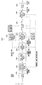
- An image encryption apparatus 100 (first image encryption apparatus) being the first embodiment of the image encryption apparatus of the present invention has input means 101, encryption area specifying means 102, image conversion means 103, key-related image generation means 104, information embedding means 105, pixel value conversion means 106 and output means 107.
- the input means 101 obtains data to be the target of the encryption, and converts it into an image (hereinafter, referred as an input image) in a format for which an encryption process can be performed.
- the image may be an image in the bitmap format.
- the input means 101 converts the format of input data as needed, and provides it as an input image for the subsequent processes.
- the input data may be, for example, image data, electronic document data such as Microsoft Office documents and Adobe PDF documents, or non-image data such as HTML and XML.
- the input can also be performed by reading it by an optical device such as a scanner and digital camera.
- the input means 101 converts a part or the whole of the data into an image (input image) in a format that is suitable for the encryption process, such as the uncompressed bitmap format.
- the encryption region specifying means 102 specifies a region for which encryption is desired, for the input image generated by the input data 101.
- the specification of the encryption region is performed through, for example, a GUI.
- the encryption region may be specified in advance by coordinate information and the like.
- the encryption region to be specified is not limited to one, and there may be a plurality of it.
- the image within the encryption region is referred to as an "encryption-region image”.
- the encryption region specifying means 102 generates information (hereinafter, referred to as borderline information) related to the outer frame (borderline) of the encryption region and to the borderline in a minimal area within the encryption region.
- the borderline information is referred to by the image conversion means 103, the information embedding means 105 and the pixel value conversion means 106.
- the image conversion means 103 performs an image processing based on an encryption key for the image (encryption-region image) in the region specified by the encryption region specifying means 102, to convert the image in the encryption region into an image in which the original contents cannot be recognized (hereinafter, referred to as intermediate image 1).
- the encryption key may be, for example, a password, a key stored in an ID card input through a GUI (Graphical User Interface), or biometric information such as a fingerprint, vein and iris used when a biometric authentication apparatus performs authentication.
- GUI Graphic User Interface
- biometric information such as a fingerprint, vein and iris used when a biometric authentication apparatus performs authentication.
- the key-related information generation means 104 performs a conversion process for the encryption key, and generates encryption key-related information.
- the information embedding means 105 embeds the encryption key-related information generated by the key-related information generation means 104 into the encryption-region image generated by the image conversion means 103, to generate intermediate image 2.
- the pixel value conversion means 106 converts the pixel value of the intermediate image 2 so that the position of the encryption region in the image can be specified at the time of the decryption, and generates and outputs the encrypted image.
- the position of the encryption region may be specified at the time of the decryption without the pixel-value conversion. In such a case, the pixel-value conversion may be omitted.
- the output means 107 converts the format of the encrypted image as needed, and outputs output data.
- the operation of the image encryption apparatus 100 configured as described above is explained.
- the input means 101 obtains input data and converts the format of the input data.
- any data that a human can visually recognize such as a monochrome image, color image, document data etc. may be input, regardless of their format.
- the input means 101 converts the input data into a format that is suitable for the encryption process, such as the uncompressed bitmap format, and gives the input image obtained by the conversion to the encryption region specifying means 102.
- the encryption region specifying means 102 specifies, in the input image, a region specified by a user of the apparatus 100 through a GUI (Graphical User Interface) and the like, as an encryption region.
- a part of the input image may be specified, or the entirety may be specified when the entire image needs to be kept confidential.
- the user of the apparatus 100 specifies the part as the encryption region.
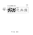
- Fig. 6 is a diagram illustrating the method of specifying the encryption region by the encryption region specifying means 102.
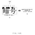
- the region surrounding the display " " is specified as an encryption region 111.
- an encryption-region image 120 illustrated in Fig. 7 is specified.
- the image conversion means 103 performs image conversion based on an input encryption key for the encryption-region image specified by the encryption region specifying means 102, so that the contents of the encryption-region image become unrecognizable. For the image conversion, for example, a method disclosed in patent document 1 is applied.
- a binary bit string "10011010010" is used as an encryption key 130.
- "1" indicates an "operation exchanging adjacent columns or rows”
- "0" indicates that "no operation is to be performed”.
- the encryption-region image 120 illustrated in Fig. 8 (B) is picked up.
- the encryption-region image 120 is longitudinally divided into eight equal pieces, to divide the encryption-region image 120 into eight columns of segments 121C. Then, the upper seven bits ("1001101") in the encryption key 130 are associated with the boundaries between the eight columns of segments 121C sequentially from left, and the operations corresponding to the bit value described above are performed for adjacent two segments 121C with respect to each boundary sequentially from the left to the right. As a result, the encryption-region image 120 is converted into an image 140 illustrated in Fig. 8(C) .
- the image 140 is laterally divided into four equal pieces, to divide the image 140 into four rows of segments 141R.
- the upper three bits ("100") of the encryption key 130 are associated with the three boundaries between the four rows of segments 141R sequentially from the top, and the exchange operations similar to those performed with the longitudinal division are performed for adjacent two segments 141R with respect to each boundary, in units of rows sequentially from the top.
- Fig. 8(D) an image 150 in which a scramble process is performed for a region in the encryption-region image 120 divided in a grid pattern in the longitudinal and lateral directions is obtained.
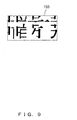
- an intermediate image 150 (intermediate image 1) illustrated in Fig. 9 in which the contents of the image have become unrecognizable is generated from the encryption-region image 120.
- various processes such as inversion side to side and up and down, and rotation may be applied, and any means will do as long as it is a method for making the contents of an original image unrecognizable to human eyes on the basis of an encryption key.
- the key-related information generation means 104 performs certain conversion for the encryption key that the image conversion means 103 used for the image conversion, to generate encryption key-related information.
- the conversion method methods such as encryption, function transformation, hash transformation may be applied.
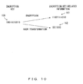
- FIG. 10 An example of a method for generating encryption key-related information by the key-related information generation means 104 is illustrated in Fig. 10.
- Fig. 10 illustrates an example of encryption and hash transform.
- the information embedding means 105 embeds the encryption key-related information generated by the key-related information generation means 104 into the intermediate image 1 generated by the image conversion means 103.
- the encryption key-related information is used for authentication at the time of the decryption of an encrypted image generated by the image encryption apparatus 100.
- the information embedding means 105 divides the intermediate image 1 into a plurality of equal minimal regions, and embeds each bit in the bit string into each of the minimal regions.
- four specific methods of embedding encryption key-related information by the information embedding means 105 are picked up and the respective methods are explained.
- information is embedded into an encrypted image by converting the pixel value of the minimal region (also referred to as an embedding region) in the intermediate image 1.
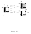
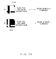
- information is embedded by a method in which, when the pixel value of a rectangle region inside the embedding region is subtracted by 10%, bit information of "1", or when no subtraction is performed, bit information of "0" is expressed.
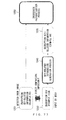
- Fig. 11 The method is illustrated specifically in Fig. 11 .
- the pixel value of black is set to "0”
- the pixel value of white is set to "255".
- the pixel values of a rectangle region 171 the region enclosed by the rectangle frame drawn with the broken line
- the pixel values of a rectangle region 171 are equally subtracted by 10%, as illustrated in Fig. 11(B) .
- no change is performed for the pixel values of the rectangle region 170, as illustrated in Fig. 11(C) .
- the image in the embedding region 170 remains the same as the original. While the information of "1" is embedded by subtracting the pixel value by 10%, other methods of converting a pixel value such as addition, subtraction, multiplication and division, nonlinear conversion may be adopted. In addition, the part of which pixel values are to be converted in the embedding region is not limited to a portion, and it may be the entire region.
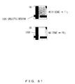
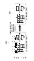
- information is embedded into the encryption region by inverting pixel values of the embedding region.
- Fig. 12 is a diagram illustrating an example of applying the method to a case in which the embedding region is a monochrome image.
- a process is performed so that, when embedding "1" into the embedding region illustrated in Fig. 12(A) , the pixel values in the region are inverted as illustrated in Fig. 12(B) , and when embedding "0", the pixel values of the region are not inverted, as illustrated in Fig. 12(C) .
- the inversion process may be applied not only to a monochrome image but also to a color image.
- the target image is an image in the RGB format, it becomes possible by inverting each of the pixel values of the three colors of R, G, B independently.
- the part of which pixel value is to be inverted is not limited to the entirety of the embedding region, and the embedding may be performed by inverting a portion.
- encryption key-related information is embedded into the encryption region in accordance with inverting patterns that define the part of which pixel values are to be inverted in the embedding region.
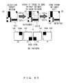
- FIG. 13 Examples of the inverting patterns are illustrated in Fig. 13 .
- An inversion pattern 191 illustrated in Fig. 13 (A) in which a black region exists in the upper right is an inversion pattern (pattern 00) corresponding to the bit string "00" (two-bit information).
- An inversion pattern 192 illustrated in Fig. 13 (B) in which a black region exists in the lower right is an inversion pattern (pattern 01) corresponding to the bit string "01" (two-bit information).
- An inversion pattern 193 illustrated in Fig. 13 (C) in which a black region exists in the lower left is an inversion pattern (pattern 10) corresponding to the bit string "10" (two-bit information).
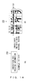
- Fig. 14 is a diagram illustrating a method for embedding the four kinds of inverting patterns illustrated in Fig. 13 into an embedding region in the intermediate image 1 while associating them with a bit string of encryption key-related information.
- encryption key-related information 200 is a seven-bit bit string "1011010”.
- an intermediate image 150 (intermediate image 1) is divided into 8 (lateral direction) x 4 (longitudinal direction), i.e., total of 32 minimal regions (embedding regions) 151.
- every two bits from the top of the encryption key-related information 200 are sequentially embedded into each embedding region 151.
- the information to be embedded first are the first two bits "10" of the encryption key-related information, and the embedding region 151 to be the target of the embedding is the leftmost region of the top row.
- two bits are sequentially taken out from the bit string subsequent to the first two bits, and the patterns corresponding to the bit patterns are assigned to the second embedding region 151 from the left of the top row and the subsequent embedding regions, sequentially from left to right, as illustrated in Fig. 14 (B) .
- FIG. 15 A specific method of embedding two bits of encryption key-related information into an embedding region is illustrated in Fig. 15 .
- a pattern 193 pattern 10) illustrated in Fig 15(B) is selected.
- the region corresponding to the region (black part in the drawing) in the embedding region 151 defined by the inverting pattern 193 is inverted.
- the image in the embedding region 151 illustrated in Fig. 15(A) is converted into an image 210 illustrated in Fig. 15(C) .
- the next two bits "11" are embedded into the embedding region 151 on the immediate right of the embedding region for which the embedding has just been performed, by the same method.
- a plurality of inverting patterns are prepared in association with the respective patterns of partial bit strings of encryption key-related information, and the encryption key-related information is embedded into the intermediate image 1 by inverting pixel values of a region defined by the inverting pattern corresponding to the information to be embedded (partial bit string) in the embedding region.
- intermediate image 2 into which the encryption key-related information is embedded, is generated.
- FIG. 16 Other inverting patterns are illustrated in Fig. 16 .
- Four formats of inverting patterns 211-214 illustrated in Fig. 16(A) are patterns expressing four sets of two-bit information ("00", “01”, “10”, “11") by dividing an embedding region into two in the two directions i.e., the longitudinal and lateral directions.
- Four formats of inverting patterns 221-224 illustrated in Fig. 16 (B) are patterns expressing four sets of two-bit information by converting pixel values on the edge part of an embedding region. While the inverting patterns are all in a set of four kinds, the number of formats of the inverting patterns may be set arbitrarily in accordance with the number of bits of information to be embedded into the embedding region.
- information is embedded into the embedding region by embedding information into the intermediate image 1 using a watermark.
- the image to be the target of the embedding of the encryption key-related information here is the intermediate image 150 (intermediate image 1) illustrate in Fig. 9 , and as an example of a watermark system that is suitable for embedding information into such an image, there is a method disclosed in Japanese Patent Application No. 2006-266015 (hereinafter, patent document 3) in the Japan Patent Office.
- the embedding system is characterized in that four kinds of image patterns 23-234 illustrated in Figs. 17(A)-(D) are embedded into a document image in an indistinctive manner.
- a flat region is searched in a black image in the intermediate image 150, and one of the image patterns 231-234 illustrated in Figs.
- Fig. 19 is a diagram illustrating the result of the embedding of the image patterns 231-234 applying the system mentioned above into the intermediate image 150 illustrated in Fig. 18 .
- protruding parts 251 represent the parts in which encryption key-related information is embedded.
- the information embedding means 105 uses one of four kinds of methods of embedding encryption key-related information described above to embed encryption key-related information into the encryption region (intermediate image 1), and generates the intermediate image 2.
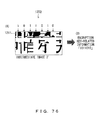
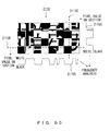
- Fig. 20 is a diagram illustrating intermediate image 300 (intermediate image 2) that the information embedding means 105 generated by embedding encryption key-related information into the intermediate image 150 illustrated in Fig. 9 using the first method of embedding encryption key-related information (information embedding method by the pixel value conversion).
- the pixel value conversion means 106 For the intermediate image 2 into which encryption key-related information is embedded, the pixel value conversion means 106 generates an image that forms an approximately stripe pattern by converting the pixel values of the intermediate image 2 with respect to its lateral direction with a certain periodicity and converts the pixel values of the intermediate image 2 with respect to its longitudinal direction with a certain periodicity. For the generation, for example, the pixel value conversion method disclosed in patent document 1 may be used.
- Fig. 21 is a diagram illustrating a method according which the pixel value conversion means 106 performs the pixel value conversion process for the intermediate image 2.
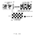
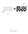
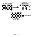
- a checkerboard-pattern image 310 illustrated in Fig. 21(B) is prepared.
- the checkerboard-pattern image (checker-pattern image) 310 is composed of white regions 311W and black regions 311B that are alternately disposed like a matrix, and its size is the same as that of the intermediate image 300.
- the size of the white region (colorless part) 311W and the black region (colored part) 311B is the same as that of the embedding regions, and their positions are the same as the alignment position of the embedding regions.
- the pixel value conversion means 106 performs the conversion in which, in the pixels in the intermediate image 300, the region corresponding to the colored part of the checkerboard pattern image 320 is subjected to an inverting process. As a result, as illustrated in Fig. 21(C) , a pixel value converted image 320 forming an approximately stripe pattern as a whole is obtained.
- the output means 107 performs the format conversion of the pixel value converted image 320 (encrypted image 320) as needed and outputs it. It may be converted into another image format and output; or when there is no particular need for conversion, the encrypted image 320 may be output in the format without change, or it may be converted into electronic-document data such as a Microsoft Office document and Adobe PDF document or into non-image data such as HTML and XML. In addition, it may be output in the form of presentation on a display or printing on a physical medium such as paper.
- the pixel value conversion process is performed using the checkerboard-pattern image 310 composed of the white regions 311W and the black regions 311B in the same arrangement pattern as the arrangement pattern of the embedding regions in encryption key-related information. Therefore, on the side that decrypts the encrypted image, it becomes possible to detect the detail positions of the borderlines between the respective embedding regions into which encryption key-related information is embedded, on the basis of the stripe pattern of the encrypted image (pixel value converted image 320).
- data input to the image encryption apparatus 100 is converted within the image encryption apparatus 100 into the encrypted image 320 (pixel value converted image 320) illustrated in Fig. 22 , by the processes in the input means 101, encryption region specifying means 102, image conversion means 103, key-related information generation means 104, information embedding means 105 and pixel value conversion means 106.
- the image encryption apparatus 100 converts the input data into an input image 110 illustrated in Fig. 6 using the input means 101.
- image processing is performed to the input image 110 to covert it sequentially into the intermediate image 1, intermediate image 2 and encrypted image.
- the encrypted image 320 of the input image 110 is generated.
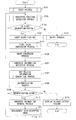
- Fig. 23 is a flowchart illustrating the entire processes of the image encryption apparatus 100.
- the input data for the apparatus 100 may be, image data, or may be electronic document data such as Microsoft Office documents and Adobe PDF document, or non-image data such as HTML and XML.
- the input can also be performed by reading it by an optical device such as a scanner and digital camera.
- the input means 101 converts a part or the entirety of the input data into an image (input image) in a format that is suitable for the encryption process such as the uncompressed bitmap format, and outputs it to the encryption region specifying means 102.
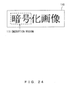
- An example of the input image 110 is illustrated in Fig. 24 .
- an encryption user performs an encryption region specifying process for specifying a region to be encrypted in the input image (S2).
- the user (hereinafter, referred to as an encryption user) generating an encrypted image specifies, when the region to be encrypted exists in the input image, the encryption region.
- the encryption user inputs an encryption key (S3).
- the image encryption apparatus 100 starts the encryption process.
- a method of specifying the encryption regions is illustrated in Fig. 24 .
- the encryption region 111 is specified in a rectangle shape.
- the shape for specifying the encryption region is not limited to the rectangle shape, and various shapes may be specified.
- the encryption user does not specify the encryption region.
- the input image is output without change and the process is terminated.
- the encryption key may be, for example, a password. Numerals, character strings and the like can be used for the password.
- the encryption key input by the encryption user is converted into binary data, and used for the encryption process of the input image.
- the encryption key is, for example a numeric value or character string.
- the encryption key is a numeric value "1234"
- when it is converted into unsigned binary binary data "10011010010” illustrated in Fig. 25(B) is obtained.
- the encryption key is a character string "ango"
- 32-bit binary data "01100001011011100110011101101111” illustrated in Fig. 25(B) is obtained.
- the numeric value "1234" is input as the encryption key is explained. That is, it is assumed that the encryption key is processed as binary data "10011010010".
- an image conversion process in which the image in the encryption-target region is converted so that the original contents become unrecognizable is performed (S4).
- the image conversion process is explained with reference to Fig. 26 and Fig. 27 .
- an image 120 (hereinafter, referred to as the encryption-region image 120) in the encryption region 111 in Fig. 24 is divided in a grid pattern.
- the encryption-region image 120 is divided into a plurality of minimal regions 121.
- the encryption-region image 120 is divided into eight units of segment 121C in the column direction that is a group of the minimal regions 121 in the column direction.
- the respective segments 121C are exchanged in units of adjacent segments, from left to right with sequential slide, in accordance with the upper seven bits ("1001101") of the encryption key 130 ("10011010010" illustrated in Fig. 27(B) , generating an image 140 illustrated in Fig.
- the image 140 is divided into three units of segment 141R that is a group of the minimal regions 121 in the row direction. Then, the respective segments 141R are exchanged in units of adjacent segments, from top to bottom with sequential slide, in accordance with the upper three bits ("100") of the encryption key 130, generating an intermediate image 150 (intermediate image 1) illustrated in Fig. 27(D) .
- the encryption-region image 120 is converted into the intermediate image 150 (intermediate image 1) in which the original contents cannot be recognized, by performing exchange in the encryption-region image 120 in units of columns and lines in accordance with the encryption key 130.
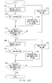
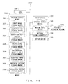
- Fig. 28 is a flowchart illustrating details of the image conversion process described above (process in step S4 in Fig. 23 ) performed by the image conversion means 103. First, image conversion in units of columns is performed.
- the leftmost column (the segment in the column direction described above) in the encryption-region image becomes the first target column, and the first one bit of the encryption key is obtained (S41). Whether the one bit is "0" or "1” is determined (S42). Then, when the one bit is "0", nothing is performed, and the process may proceed to step S44. On the other hand, in the case of "1", the first target column is exchanged with its next column on the right in units of columns (S43), and the process may proceed to step S44.
- step S44 whether the target column has moved to the column immediately preceding the rightmost column is determined, and if it has not reached the column, the target column is moved to the second column from the left (S45), and return to step S41 is performed.
- step S41 the second bit of the encryption key is obtained. Then, when the second bit is "0", nothing is performed, and in the case of "1", the second column and its next column on the right are exchanged in units of columns (S42-S43).
- step S44 the encryption-region image 120 illustrated in Fig. 27(A) is converted into the image 140 illustrated in Fig. 27(C) , in accordance with the encryption key 130.
- steps S46-S50 are performed for the image generated by the column-exchange process described above.
- steps S46-S50 only the process target changes from the "columns" (segments in the column direction) to the "rows” (segments in the row direction), and the target row simply shifts downward by one row from the top row of in the image.
- steps S46-S50 are repeated until, in step S49, it is determined that the target row immediately precedes the last row in the image.
- the columns and rows in the encryption-region image are exchanged in accordance with the encryption key, and converted into the intermediate image 1 in which the original contents cannot be recognized.
- the image conversion process of the encryption-region image by the image conversion means 103 may be any processing method as long as it is a method for making the original image contents unrecognizable on the basis of an encryption key. For example, processes such as exchange in units of minimal regions, inversion side to side and up and down, or rotation may be applied.
- step S4 an encryption key input by an encryption user is converted into encryption key-related information by the key-related information generation means 104 (S5).
- the encryption key-related information is generated from the encryption key for a security reason described below.
- a countermeasure is implemented, for example, by performing hash transformation for the encryption key and embedding the hash value obtained by the transform into the encryption region.
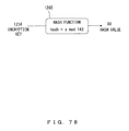
- hash transformation is performed for the encryption key using a hash function 330 with which the reminder of the division of the decimal value x of the encryption key by "143" (decimal number) is taken as the hash value, and the transformed value is embedded into the encryption region in the intermediate image 1 as the encryption key-related information.
- the key-related information generation means 1004 generates "encryption key-related information" from an “encryption key” using hash transformation as described above and the like.
- step S5 an "information embedding process" is performed by the information embedding means 105, in which the encryption key-related information generated by the key-related information generation 104 is embedded into the minimal region (embedding region) in the image-target area divided by the image conversion means 103 (S6).
- Fig. 30 is a flowchart illustrating details of the information embedding process.
- a minimal region to be the target of the embedding of the encryption key-related information is extracted from the encryption region (encryption-region image) (S61).
- “embedding information” to be embedded into the minimal region is obtained from the encryption key-related information, and an “information embedding” process to embed it into the minimal region is performed (S62).
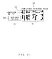
- FIG. 31 is an example of embedding the embedding information into one minimal region bit by bit.
- a hash value 203 is converted from "90" (decimal number) to binary data "1011010".
- the bits of the binary data are embedded into a minimal region 121 in the encryption region (encryption-region image 120) bit by bit sequentially from the top bit.
- the bit-by-bit embedding is performed sequentially from the upper left minimal region 121 in the encryption region.
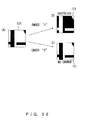
- Fig. 32 is a diagram illustrating a method of embedding the encryption key-related information into each minimal region 121 in the encryption region.
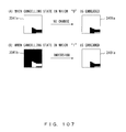
- embedding information "1" one-bit information" into the minimal region 121 illustrated in Fig. 32(A)
- the pixel values of the image in the minimal region 121 are all inverted, as illustrated in Fig. 32(B) .
- embedding information "0” the pixel values of the image in the minimal region 121 are not changed, as illustrated in Fig. 32(C) .
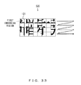
- Fig. 33 is a diagram illustrating an order of obtaining the minimal region in the encryption region by the information embedding means 105.
- the information embedding means 105 obtains the minimal region 121 sequentially one by one by zigzag scanning moving from left to right starting from the leftmost minimal region 121 on the top line (highest row) in the encryption region (encryption-region image 120), and upon reaching the right end, moving to the left end of the line (row) immediately below.
- step S62 When the process in step S62 is completed, whether all information in the encryption key-related information has been embedded into the encryption region is determined (S63), and when all binary data in the encryption key-related information has not been embedded yet, return to step S61 is performed.
- steps S61-S63 are repeated until all information in the encryption key-related information is embedded into the encryption region, and when it is determined, in step S63, all information in the encryption key-related information has been embedded into the encryption region, the process of the flowchart are terminated.
- An intermediate image 300 obtained as a result of the embedding of the encryption key-related information (in this example, the hash value 203) into the intermediate image 150 (intermediate image 1) in Fig. 27 .
- information to be embedded into an encryption region is assumed to be encryption key-related information, but other information (such as a user ID) may be embedded along with the encryption key-related information, or the other information only may be embedded.
- step S6 a "pixel value conversion process" to convert the pixel values of the image (intermediate image 2) in the encryption region is performed by the pixel value conversion means 106 (S7).
- the pixel value conversion means 106 performs conversion for the pixel values of the image in the encryption region, to make the image after the conversion form, for example, an approximately periodic pattern.
- Fig. 35 is a flowchart illustrating details of the pixel value conversion process.
- Fig. 36 The definitions of variables used in the flowchart are described in Fig. 36 .
- the lateral size of the minimal region 121 is assumed as m, and its longitudinal size is assumed as n.
- the lateral size of the image (intermediate image 2) in the encryption region is assumed as w, and its longitudinal size is assumed as h.
- the values of the pixel (pixel values) in the position of coordinates (i,j) are expressed as P(i,j) in the encryption-region image for which the orthogonal coordinate system is set as described above.
- 0 is set to i and j, and the process starts from the pixel of which coordinates (x,y) are (0,0) (371).
- (i/m + j/n) mod 2 is calculated, and whether the reminder of the calculation is "0" is determined (S72).
- the process may proceed to step S74 without any operation, and in the case of "1", the pixel values P(0,0) are inverted (S73).
- the process in step S73 is completed, the process may proceed to S74.
- step S73 the process in step S73 is performed for the minimal region 121 of which either of the row number or the column number only is an odd number.
- the pixel values of the minimal region 121 in odd-numbered columns, and in an odd-numbered row, the pixel values of the minimal region 121 in even-numbered rows are inverted.
- the image (intermediate image 2) in the encryption region is converted into an approximately periodic pattern.
- steps S72-S74 are repeated while increasing the value of i as 0, 1, 2, ... until, in step S74, it is determined that the target pixel has reached the rightmost pixel. Then, when it is determined in step S74 that it has reached the rightmost pixel, the process may proceed to step S76.
- the pixel values are converted while performing sequential zigzag scanning by line from left to right, top to bottom, starting from the leftmost pixel in the top line. Then, when it is determined in step S76 that the target pixel has reached the rightmost pixel of the bottom line, the process is terminated.
- An encrypted image 320 generated by converting the pixel values of the intermediate image 300 by the pixel value conversion means 106 is illustrated in Fig. 37 . Meanwhile, the inversion process of pixel values by the pixel value conversion means 106 may be performed not only for a monochrome image but also for the case of a color image.
- FIG. 38 An inversion method for a color image is illustrated in Fig. 38 .
- the inversion process is performed, for a black pixel, by converting it into a white pixel (by converting the pixel value from "0" to "255"), and for a white pixel, by converting it into a black pixel (by converting the pixel value from "255" to "0").
- the inversion for a color image may be performed by independently inverting the pixel value of each color constituting the pixel value.
- a pixel is composed of three pixel values of R (red), G (green), B (blue), as illustrated in Fig. 38(B) .
- eight bits are assigned to each color of RGB. In this case, as illustrated in Fig.
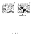
- FIG. 39 An example of the inversion of a color image is illustrated in Fig. 39 .
- a color image 710 in Fig. 39(B) rectangle regions being parts of a color image 700 in Fig. 39 (A) are inverted.
- the two rectangle regions in the color image 710 indicated by the thick arrows in the drawing are the inverted parts.
- pixel value conversion may be performed in a color image, in a similar manner as in a monochrome image.
- step S7 When the process in step S7 is completed, the input image is replaced with the encrypted image (S8). Next, whether or not to terminate the encryption process is determined (S9). With this determination, when there is another region to be encrypted in the input image, return to step S2 is performed, and the encryption process is continued. On the other hand, when there is no other encryption-target region in the input image, the completion of the encryption process is determined, and the encrypted image at that time is subjected to format conversion as needed and output as output data (S10), and the process of the flowchart is terminated.
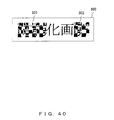
- encryption for a plurality of regions in an input image may be performed. An example of it is illustrated in Fig. 40 . In an encrypted image 800 illustrated in Fig. 40 , images in two regions 801, 802 are encrypted.
- Fig. 41 is a diagram illustrating the configuration of the second embodiment of the image encryption apparatus of the present invention.
- the same numerals are given to the same constituent elements as the constituent elements provided in the image encryption apparatus 100 illustrated in Fig. 5 .
- An image encryption apparatus 400 (a second image encryption apparatus) being the second embodiment of the image encryption apparatus of the present invention has input means 101, encryption area specifying means 102, information embedding means 403, key-related image generation means 104, image conversion means 405, pixel value conversion means 106, and output means 107.
- the processing order of the image conversion means and the information embedding means is inverse of that in the image encryption apparatus 100. Therefore, the image encryption apparatus 400 is configured so as to perform image conversion (scramble) after embedding encryption key-related information into an encryption region in an input image.
- the input means 101 converts input data into an input image 110 illustrated in Fig. 42 in the same manner as in the image encryption apparatus 100.
- the encryption region specifying means 102 specifies an encryption region 111 with respect to the input image 110, as illustrated in Fig. 42 .
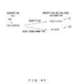
- the encryption key-related information generation means 104 converts an encryption key 130 ("10011010010") to encryption key-related information.
- the generation is performed by encryption, hash transformation and the like as illustrated in Fig. 43 .
- encryption key-related information 161 is generated by encryption
- encryption key-related information 162 is generated by hash transformation.
- the information embedding means 403 embeds encryption key-related information 200 (in this example, "1011010") illustrated in Fig. 44(A) into a minimal region (embedding region) 501 in an encryption region 500 using, for example, the first method of embedding encryption key-related information described above.
- the encryption region 500 is divided into minimal regions 501 in a similar manner as in the encryption region 120 described above.
- the information embedding means 403 inverts the minimal regions 501 that corresponds to the bit "1", and leave the minimal regions 501 that correspond to the bit "0" as they are.
- the information embedding means 403 generates intermediate image 600 (intermediate image 1) illustrated in Fig. 45 .
- the image conversion means 405 performs an exchange process of segments 601C in eight columns in the intermediate image 600 illustrated in Fig. 46 (B) in accordance with the upper seven bits ("1001101") of the bit string of the encryption key 130 ("10011010010") illustrated in Fig. 46(A) , to generate an image 610 illustrated in Fig. 46(C) .
- an exchange process of segments 611R in four rows in the image 610 is performed, to generate intermediate image 620 (intermediate image 2) illustrated in Fig. 46(D) .
- the image conversion means 405 ultimately generates the intermediate image 620 (intermediate image 2) illustrated in Fig. 47 .
- the pixel value conversion means 106 converts the intermediate image 620 (intermediate image 2) illustrated in Fig. 48 (A) into a pixel value converted image 630 illustrated in Fig. 48(C) referring to a checkerboard-pattern image 310 illustrated in Fig. 48(B) .
- the position of the encryption region may be specified at the time of the decryption without the pixel-value conversion.
- the output means 107 performs the format conversion of the pixel value converted image 630 (encrypted image 630) as needed and output it.
- the output in the same format as the pixel value converted image 630 is desired, it may be output without change; or it may be converted into another image format and output; or when there is no particular need for conversion, the encrypted image 630 may be output in the format without change, or it may be converted into electronic-document data such as a Microsoft Office document and Adobe PDF document or into non-image data such as HTML and XML.
- the data output here is output from the image encryption apparatus 400 as output data.
- data input to the image encryption apparatus 400 is converted into the encrypted image 630 (pixel value converted image 630 in Fig. 48 (C) ) illustrated in Fig. 49 , by the processes in the input means 101, encryption region specifying means 102, information embedding means 403, key-related information generation means 104, image conversion means 405, pixel value conversion means 106 and output means 107 disposed within the image encryption apparatus 400.
- the image encryption apparatus 400 converts the input data into the input image 110 illustrated in Fig. 42 using the input means 101.
- image processing is performed to the input image 110 to covert it sequentially into the intermediate image 1, intermediate image 2 and encrypted image.
- the encrypted image 320 of the input image 630 is generated.
- Fig. 50 is a flowchart illustrating the entire processes of the image encryption apparatus 400.
- the same step numbers are assigned to the steps of which processing contents are the same as those in the flowchart in Fig. 23 described above.
- the processes that are different from those in the flowchart in Fig. 23 are explained with emphasis, and the explanation of the same processes as those in Fig. 23 is simplified or omitted.
- step S1-S3 the early process procedure in the image encryption apparatus 400 is the same as that in the image encryption apparatus 100.
- the late process procedure (steps S7-S10) is also the same as that in the image encryption apparatus 100.
- the image encryption apparatus 400 inputs an encryption key in step S3, and next, performs the "key-related information generation process" to generate encryption key-related information (S5).
- the key-related information generation process is a similar process to the key-related information generation process in the image encryption apparatus 100, which is a process of generating encryption key-related information from the input encryption key.
- the information embedding means 403 the "information embedding process" to embed the encryption key-related information into the input image input in step S1 is performed (S106).
- the information embedding process is explained.
- the information embedding means 403 divides the encryption region 11 into eight pieces in the column direction and four pieces in the row direction as illustrated in Fig. 52 , to divide the encryption region 111 into 32 pieces of rectangle minimal regions 111a.
- the algorithm of the embedding process of the encryption key-related information is the same as the algorithm illustrated in the flowchart in Fig. 30 described above executed by the information embedding means 105 of the image encryption apparatus 100.
- the image encryption apparatus 400 and the image encryption apparatus 100 differ with respect to the image to be the target of the embedding of encryption key-related information.
- the information embedding means 105 of the image encryption apparatus 100 embeds encryption key-related information into the intermediate image 1
- the information embedding means 403 of the image encryption apparatus 400 embeds encryption key-related information into the image in the encryption region 111 in the input image 110.
- FIG. 53 A method of embedding image encryption key-related information into the encryption region 111 by the information embedding means 403 is illustrated in Fig. 53 .
- the hash value 162 ("1011010" is used as the encryption key-related information as illustrated in Fig. 53 (A) .
- the bit string of the hash value 162 is embedded into the minimal regions 111a of in the encryption region 111 bit by bit sequentially from the top bit.
- the selection order of the minimal regions 111a in this case is similar to that in the case of the information embedding means 105 of the image encryption apparatus 100.
- FIG. 54 An example of embedding a bit in the hash value 162 into the minimal regions 111a in the encryption region 111 is illustrated in Fig. 54.
- Fig. 54 illustrates an example of embedding the top bit of the hash value 162 into the leftmost minimal region 111a in the top line (highest row) of the encryption region 111.
- the image in the leftmost minimal region 111a in the highest row in the encryption region 111 is converted as illustrated in Fig. 54(B) .
- the pixel values of the images in the other minimal regions 111a in the encryption region 111 are also processed in a similar manner in accordance with the value of the bit to be embedded.
- An intermediate image 600 (intermediate image 1) that the information embedding means 403 generated by embedding the hash value 162 ("1011010") into the minimal regions 111a in the encryption region 111 is illustrated in Fig. 55 .
- information to be embedded into an encryption region is assumed to be encryption key-related information, but other information (such as a user ID) may be embedded along with the encryption key-relates information, or the other information only may be embedded.
- step S106 an "image conversion process" for the intermediate image 1 is performed by the image conversion means 405 (S107).
- the algorithm of the image conversion process is the same as the algorithm illustrated in the flowchart in Fig. 28 described above.
- the image conversion process is performed not for the "input image” but for the "intermediate image 1".
- the image conversion process is performed using the method illustrated in Fig. 46 described above, and by this process, the intermediate image 620 (intermediate image 2) illustrated in Fig. 47 described above is generated.
- a "pixel value conversion process” is performed for the intermediate image 2 by the image conversion means 106 (S7).
- the algorithm of the pixel value conversion process is the same as the algorithm illustrated in the flowchart in Fig. 35 .
- the output means 107 performs the format conversion of the pixel value converted image 620 (encrypted image 620) as needed and outputs it. It may be converted into another image format and output; or when there is no particular need for conversion, the encrypted image 620 may be output in the format without change, or it may be converted into electronic-document data such as a Microsoft Office document and Adobe PDF document or into non-image data such as HTML and XML. In addition, it may be output in the form of presentation on a display or printing on a physical medium such as paper.
- the data output here is output from the image encryption apparatus 400 as output data.
- steps S8-S10 illustrated in the flowchart in Fig. 23 described above are performed, encrypting the image in the encryption region in the input image specified by the encryption user, and the process is terminated at the time when there is no more specification of the encryption region.
- the image in the encryption region in the input image specified by the encryption user is encrypted.
- a color encrypted image 710 as illustrated in Fig. 39(B) described above and an encrypted image 800 as illustrated in Fig. 40 described above in which the images in a plurality of encryption regions 801 and 802 are encrypted are generated.
- encryption key-related information is embedded within an encryption region, even when there is no margin apart from the encryption region, encryption key-related information can be embedded within an image (referring to both a printed matter and a digital image) .
- encryption key-related information is embedded using an embedding method that is highly resistant to distortion, at the time of decryption, encryption key-related information can be detected accurately even from an image that has gone through a process such as printing, copying and scanning. Therefore, it becomes possible to provide, at the decrypting side, a function to perform user authentication based on the detected encryption key-related information, so as to enable only a user having a legitimate right can restore and view the original image.
- the image decryption apparatus of the present invention is described.
- the image decryption apparatus is an apparatus decrypting an encrypted image generated by the first embodiment of the image encryption apparatus of the present invention (image encryption apparatus 100).
- Fig. 56 is a diagram illustrating the first embodiment of the image decryption apparatus of the present invention.
- An image decryption apparatus 1000 (first image decryption apparatus) being the first embodiment of the image decryption apparatus of the present invention has an input means 100X, encrypted position detection means 1001, pixel value conversion means 1002, embedded information detection means 1003, key-related information generation means 1004, authentication means 1005, embedded information removal means 1006, image conversion means 1007 and output means 1008.
- the input means 100X obtains input data, performs format conversion as needed, and gives it to the next process as an input image.
- the encrypted position detection means 1001 detects an encryption region in the input image, and further detects the positions of borderlines within the encryption region.
- the position of the encryption region 1110 (corresponds to the encrypted image 320 in Fig. 22 in this example) needs to be recognized first. However, it is not sufficient just to recognize the position, and the decryption is impossible unless the positions of borderlines 1111C, 1111R in the column direction and the row direction used in the process such as scrambling performed at the time of the encryption.
- the borderlines 1111C in the column direction are borderlines between segments in the column direction to be the target of the scrambling
- the borderlines 1111R is borderlines between segments in the row direction to be the target of the scrambling (see Fig. 8 ).
- the pixel value conversion means of the image encryption apparatus performs a process of periodically converting pixel values, so, as illustrated in Fig. 58 , the position of the encryption region and the positions of the border lines can be specified by performing frequency analysis of the pixel values on the sections in the longitudinal and lateral directions.
- plural detection is also possible.
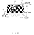
- Fig. 58 is a diagram illustrating a method with which the encrypted position detection means 1001 performs frequency analysis of the encrypted image 1100 to detect the borderlines 1111C, 1111R in the encrypted region 1110.
- a section line 1113R in the lateral direction and a section line 1113C in the longitudinal direction are drawn, and the values of the pixels on the section lines of the images in the encryption region 1110 are obtained.
- the pixel value is, maximum for white (for example, "255") and minimum for black (for example, "0").
- a waveform 1115C for the lateral direction, and a waveform 1115R for the longitudinal direction are obtained.
- the borderline 1111C and the borderline 1111R are detected, for example, using a known art of performing frequency analysis of the waveform 1115C and the waveform 1115R. Meanwhile, when there are a plurality of encryption regions in the encrypted image 1100, the positions of the encryption regions and the positions of borderlines are detected for all the encryption regions.
- a method for performing frequency analysis of the encrypted image 1100 to detect the encryption region 1110 is illustrated in Fig. 23 of patent document 1. Since the encryption region 1110 has a higher periodicity than other regions in the encrypted image 1100, the encryption region 1110 can be detected by checking the periodicities of the entire regions of the encrypted image 1100.
- the pixel value conversion means 1002 performs the cancellation of the pixel value conversion that the pixel value conversion means 106 of the image encryption apparatus 100 performed to generate the encrypted image from the intermediate image 2. For example, in a case in which conversion to a checkerboard pattern as illustrated in Fig. 21 was performed when generating the encrypted image, the cancellation of the pixel value conversion can be performed by undoing the pixel value conversion (conversion to the checkerboard pattern) using the method illustrated in Fig. 59 .
- Fig. 59 is a diagram illustrating a method with which the pixel value conversion means 1002 cancels the pixel value conversion (conversion to a checkerboard pattern) performed for an encrypted image.
- the pixel values of the parts corresponding to the regions defined with the black color in the checkerboard-pattern image 1310 of the encrypted image 1100 are all inverted.
- intermediate image 1200 illustrated in Fig. 59 (C) is generated.
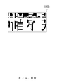
- the intermediate image 1200 (intermediate image 2') is illustrated in Fig. 60 .
- the intermediate image 1200 is the same image as the intermediate image 620 (intermediate image 2) generated by the image encryption apparatus 100, while, before the encrypted image 1100 is input into the apparatus 1000, an image process performed for the intermediate image 620 (intermediate image 620), printing, copying or intervention of a scanner may cause a noise or distortion.
- the embedded information detection means 1003 detects the encryption key-related information embedded at the time of the encryption from the intermediate image 1200 (intermediate image 2') restored by the pixel value conversion means 1002.
- the first through fourth embedding methods have been described as the methods with which the information embedding means 105 of the image encryption apparatus 100 embeds the encryption key-related information, and described below are the detection methods for the encryption key-related information in the cases in which the respective embedding methods are used.
- the first embedding method is a method for embedding encryption key-related information by changing the pixel values in a certain prescribed region (specific region) within an embedding region.
- a certain prescribed region specifically region
- a difference (edge) in the pixel values is always generated between inside and outside.
- a detection method for encryption key-related information embedded using the first embedding method is described in Fig. 61 .
- the presence/absence of an edge in the vicinity of the borderlines of a specific region in an embedding region (minimal region) is detected, and it is determined that, for a specific region having an edge as the specific region 1201 illustrated in Fig. 61(A) , the bit information of "1" is embedded, and for a specific region having no edge as the specific region 1202 in Fig. 61 (B) , the bit information of "0" is embedded.
- each bit value in the bit string of the encryption key-related information embedded in the embedding region can be detected.
- the second embedding method is a method for embedding encryption key-related information by inverting the pixel values in an embedding region.
- each bit value in the bit string of the encryption key-related information embedded in the embedding region can be detected by calculating the black-pixel rate in the embedding region.
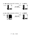
- a detection method for encryption key-related information embedded using the second embedding method is described in Fig. 62 .
- For an embedding region in which the black-pixel rate exceeds a threshold value as an embedding region 1211 illustrated in Fig. 62(A) it is determined that the pixel values were inverted at the time of the embedding, and that "1" is embedded in the embedding region. Meanwhile, for an embedding region in which the black-pixel rate is below the threshold value, it is determined that the pixel values have not been inverted, and that "0" is embedded in the region.
- the values in the bit string of encryption key-related information embedded in an embedding region can be detected.
- the third embedding method is a method for embedding encryption key-related information by inverting the pixel values of an embedding region in a region defined by a pattern associated with a partial bit string of encryption key-related information.
- the partial bit string embedded into the embedding region can be detected by detecting an edge part in the embedding region being the target of the detection, and by examining the inversion pattern corresponding to the edge part.
- Fig. 63 illustrates a detection method for encryption key-related information embedded using the third embedding method.
- a case of detecting a partial bit string of encryption key-related information from an embedding region 1221 illustrated in Fig. 63(A) is considered.
- the fourth embedding method is a method for embedding encryption key-related information by an electronic watermark.
- encryption key-related information embedded into intermediate image 2' can be detected using a predetermined detection method in the electronic watermark technique.
- this method for detecting encryption key-related information see the detection method in accordance with the watermark embedding method disclosed in patent document 3 mentioned above.
- the embedded information detection means 1003 detects encryption key-related information from intermediate image 2' by an extraction method in accordance with the embedding method for the encryption key-related information used by the information embedding means 105 of the image encryption apparatus 100.
- the key-related information generation means 1004 converts a decryption key input by a decryption user of the encrypted image into decryption key-related information, in accordance with a certain rule.
- the decryption key is the same as the encryption key used for the generation of the encrypted image.
- the key-related information generation means 1004 performs the same process as that of the key-related information generation means 104 of the image encryption apparatus 100, to generate decryption key-related information.
- the authentication means 1005 checks whether the user (hereinafter, referred to as a decryption user) currently attempting the decryption of the encrypted image has a legitimate right to view the original image, by crosschecking the encryption key detected by the embedded information detection means 1003 with the decryption key-related information generated by the key-related information generation means 1004. When the two match, the authentication means 1005 authenticates the user. When the two do not match, the decryption user is not authenticated. The authentication is based on the logic (1) described below.
- the embedded information removal means 1006 performs, when the authentication is given in by the authentication means 1005, a process for restoring the original pixel values that were changed when the encryption key-related information was embedded in to the intermediate image 1, to generate intermediate image 1'. Meanwhile, in the case in which the information was embedded by the image encryption apparatus 100 using the electronic watermark, since the embedding has been performed so as not to affect the appearance, the removal of the embedded information is not compulsory.
- the intermediate image 1' corresponds to the intermediate image 1 (see Fig. 27 ) generated by the image encryption apparatus 100. For the intermediate image 1', as well as the intermediate image 2', there is a possibility that a noise or distortion is generated in it, due to the input into the image decryption apparatus 1000 performed through a process such as printing, copying, scanning and the like.
- the image conversion means 1007 restores the original image (raw image) from the intermediate image 1' using an inverse conversion method in accordance with the conversion method that the image conversion means 103 of the image encryption apparatus 100 used for the intermediate image 1.
- Fig. 64 is a diagram illustrating a method with which the image conversion means 1007 restores the original image from the intermediate image 1'. It is assumed that an intermediate image 1400 (intermediate image 1') illustrated in Fig. 64(A) has been generated by the embedded information removal means 1006. In addition, it is assumed that the encryption key is "10011010010". This is equal to the encryption key used in the image encryption apparatus 100.
- the image conversion means 1007 first performs, as illustrated in Fig. 64(A) , a row exchange process for four segments 1401R in the row direction in the intermediate image 1400 using the upper three bits ("100") of the encryption key, to generate an image 1410 illustrated in Fig. 64(C) .
- a column exchange process for segments 1411C in the column direction in the image 1410 is performed using the upper seven bits ("1001101"), to generate an image 1500 illustrated in Fig. 64(D) .
- the output means 1008 performs format conversion of the image decrypted as described above as needed, and outputs it as output data.
- Fig. 66 is a flowchart illustrating the entire processes of the image decryption apparatus 1000.
- Input data is input to the apparatus 1000 by a user (hereinafter, referred to as a decryption user) attempting to decrypt an image in an encryption region of an encrypted image generated by the image encryption apparatus 100 to view the contents of the original image (raw image) of the encrypted image.
- the input means 100X performs format conversion of the input data as needed, and provides it as an input image for the subsequent processes (S101).
- the input data may be, for example, image data, electronic document data such as Microsoft Office documents and Adobe PDF document, or non-image data such as HTML and XML.
- the encryption target is printed or drawn on a physical medium such as paper, it can be treated as input data by reading it by an optical device such as a scanner and digital camera.
- the encrypted position detection means 1001 performs an "encrypted position detection process" for detecting the position of an encryption region included in the input image and borderline information of respective minimal regions in the encrypted region (S102).
- Fig. 67 is a diagram illustrating the outline of the encrypted position detection process.
- the encrypted image detection process is divided into two main stages: first, as illustrated in Fig. 67(A) , a rough position 1113 of an encryption region 1110 is identified. Next, on the basis of the rough position 1113, as illustrated in Fig. 67(B) , borderlines 1111C in the longitudinal direction and border lines 1111R in the lateral direction in the encryption region 1110 are detected.
- Fig. 68 is a diagram illustrating a method for detecting the rough position of the encryption region 1110. Since the pixel values in the encryption region 1110 have been changed periodically by the process in the pixel value conversion means 106 in the image encryption apparatus 100, the rough image of the encryption region 1110 can be identified by performing frequency analysis for the entirety of the encrypted image 1100. For the encrypted image 1100 illustrated in Fig. 68(A) , frequency analysis is performed by FFT (Fast Fourie Transformation) and the like in its longitudinal direction and lateral direction.
- FFT Fast Fourie Transformation
- a region 1120 having a high periodicity and a region 1130 having a low periodicity are detected for the encrypted image 1100.
- the power of the frequency corresponding to the period at the time when the pixel conversion was performed in the course of encryption tends to be prominently strong.
- the frequency analysis of the encrypted image 1100 the rough position of the encryption region 1110 and the periodicity of a borderline can be detected. Therefore, by the frequency analysis, the periodicity of borderlines 1115 in the encryption region 1110 can also be detected, as illustrated in Fig. 69(A) .
- the periodicity of the borderlines 1115 can be detected as illustrated in Fig. 69(A) , but where those borderlines 1115 are located cannot be found.
- a method illustrated in Fig. 70 the absolute positions of the borderlines 1115 are obtained.
- a pattern 1140 hereinafter, referred to as a periodic pattern 1140
- a periodic pattern 1140 having a periodicity illustrated in Fig. 70(A) is obtained.
- the process branches off depending on whether or not an encryption region has been detected as a result of the encrypted position detection process in step S102 (S103).
- the encryption user is asked to input a key (decryption key) for decrypting the encryption region (S104), and move to the subsequent decryption processes is performed.
- the authentication as a proper decryption user is given, and the original image can be viewed.
- the determination is presented to the user, and the process of the flowchart is terminated (S114).
- step S104 When the decryption key is input by the decryption user in step S104, next, for the image in the encryption region, a "pixel value conversion process" for cancelling the pixel value conversion performed by the pixel value conversion means 106 of the image encryption apparatus 100 is performed (S105).
- Fig. 72 is a diagram illustrating the pixel value conversion process performed by the pixel value conversion means 1002. Since in the image 1110 in the region (encryption region) detected by the encrypted image detection means 1001 illustrated in Fig. 72(A) , the pixel values was periodically converted at the time of the encryption, in order for the decryption, the conversion needs to be undone. For this reason, using a checkerboard-pattern image 1310 illustrated in Fig. 72(B) that the pixel value conversion means 106 of the image encryption apparatus 100 used for the pixel value conversion, a process to reset the converted pixel values is performed.
- the pixel values of the encryption region 1110 are reset.
- the image in the encryption region 1110 is a monochrome image and the pixel values were inverted at the time of the encryption
- the image before the pixel conversion can be restored by inverting the pixel values of the image in the encryption region 1110.
- the image in the encryption region 1110 is a color image
- the original image can be restored by inverting the pixel values of the image in the encryption region 1110 by using, for example, the pixel value inversion method illustrated in Fig. 38 mentioned above.
- the explanation of the flowchart in Fig. 66 is continued.
- the intermediate image 2' generated by the pixel value conversion process in step S105 is an image in which encryption key related information that was embedded at the time of the image encryption can be detected.
- the encryption key-related information being information about the encryption key to be crosschecked with the decryption key needs to be extracted from the intermediate image 2' in the encryption region.
- a "key-related information detection process" for detecting encryption key-related information from the intermediate image 2' is performed by the embedded information detection means 1003 (S106).
- Fig. 73 is a flowchart illustrating details of the key-related information detection process performed by the embedded information detection means 1003.
- a minimal region to be the first detection target is obtained from the intermediate image 2' (S121).
- the borderlines (borderlines 1111C, 1111R) of the minimal regions in the encryption region 111 have already been detected as illustrated in Fig. 71 by the encrypted position detection process in step S102, the detection starts from the top leftmost region in the minimal regions divided by the borderlines.
- a minimal region 1201 is the minimal region obtained first in step S121. After that, as illustrated on the right side in Fig. 74 , the minimal region is obtained sequentially one by one with zigzag scanning performed in the order from left to right, top to bottom.
- step S122 an "embedded information detection process” for detecting embedded information of the encryption key-related information (hereinafter, referred to briefly as “embedded information” for convenience) from the obtained minimal regions is performed (S122).
- the detection of embedded information from each minimal region is performed by determining whether the ratio of the number of black pixels in the total number of pixels in the region is above a threshold value or is below the threshold value.
- a specific detection method for detecting embedded information from the minimal regions is specified in Fig. 75 .
- the "black pixel rate” is used as a benchmark for the detection of embedded information, and the threshold for detecting the bit information "1" is set to 50%.
- the black pixel rate in a minimal region 1211a is below the threshold value as illustrated in Fig. 75(A) , it is determined that "0" is embedded in the minimal region 1212w.
- the black pixel rate in a minimal region 1211b is above the threshold value as illustrated in Fig. 75(B) , it is determined that all pixel values in the minimal region 1211b were inverted at the time of the embedding of the embedded information, and that "1" is embedded.
- the detection as described above is performed sequentially for all minimal regions 1201 in the intermediate image 1200 (intermediate image 2') with the zigzag scanning as descried on the right side in Fig. 74 , and the embedded information detection process is terminated when the detected amount of the embedded information becomes equal to the size (number of bits) of the encryption key-related information.
- the embedded information detection process is terminated when the encryption key-related information being the bit string of seven bits "1011010" is detected.
- the encryption key-related information (“1011010" illustrated in Fig. 76(B) can be detected from the intermediate image 1200 (intermediate image 2') illustrated in Fig. 76(A) .
- the detection is performed for the amount of the information.
- Fig. 77 is a diagram illustrating the positioning of the decryption-user authentication at the time when the process of step S106 is completed.
- the decryption key since they cannot be compared directly, in order to perform the identity authentication of the encryption user, the decryption key also needs to be converted into decryption key-related information 1235 with a key-related information generation process 1240, to perform a an authentication process 1250 for crosschecking the encryption key-related information and the decryption key-related information.
- step S106 a "key-related information generation process" for generating decryption key-related information from the decryption key input in step S104 is performed (S107).
- An example of the key-related information generation process is illustrated in Fig. 78 .
- the example illustrated in Fig. 78 corresponds to a case in which the image encryption apparatus 100 uses hash transformation for the generation of the encryption key-related information.
- the decryption key is converted into a hash value using a hash function 1260.
- x is the decimal expression of the decryption key.
- Fig. 78 when the decryption key x input by the decryption user is "1234" (decimal number), hash transformation is performed with the hash function 1260, and "90" (decimal number) is obtained as a hash value. By converting "90" into binary numbers, a binary bit string "1011010" is generated as the decryption key-related information.
- step S108 an "authentication process” for crosschecking the decryption key-related information obtained in step S107 with the encryption key-related information detected in step S106 to authenticate the decryption user is performed (S108).
- Fig. 79 is a flowchart illustrating the details of the authentication process performed by the authentication means 1005. After the "encryption key-related information" from the embedded information detection means 1003 and the “decryption key-related information” from the key-related information generation means 104 are respectively input, the authentication means 1005 starts the process illustrated in the flowchart in Fig. 79 .
- the encryption key-related information and the decryption key-related information are crosschecked (S131), whether they match, that is, whether the user authentication has been successful or not is determined (S132).
- S132 When it is determined in S132 that the user authentication has been successful, information "authentication succeeded” is stored in a storage means (not shown in the drawing), and the process is terminated (S133).
- S134 When it is determined in S132 that the user authentication has failed, information "authentication failed” is stored in the storage means, and the process is terminated (S134).
- step S108 When the user authentication process in step S108 is completed, whether or not authentication has been given to the decryption user is determined on the basis of the information stored in the storage means (S109), and when the authentication has been given, it is determined that the decryption user is a user having the right to view the encrypted part, and move to the process in step S110 is performed. On the other hand, when the authentication was not given, it is determined that the decryption user is a user having no right to view, and, either of the process to notify the user of the determination, or to display a different matter from the original image such as a dummy image, advertisement, link, etc. is performed (S114), and the process is terminated.
- the configuration may also be made so that, in the user authentication process in step S108, the authentication fails if the authentication was not given even when the input of the decryption key is allowed for a given number of time, for example three times.
- step S109 When it is confirmed in step S109 that the user authentication has been successful, that is, when it is confirmed that the decryption user is a user having the right to decrypt the encrypted image, the restoration process of the original image is performed.
- an "embedded information removal process" for removing the encryption key-related information from the intermediate image 2' is performed by the embedded information removal means 2006 (S110).
- Fig. 80 is a flowchart illustrating the details of the embedded information removal process.
- one bit if obtained from the top of the bit string being the encryption key-related information (S141), and top leftmost minimal region in the intermediate image 2' to which the information of the obtained one bit is embedded, is obtained next (step S142).
- Fig. 82(A) illustrates a method of removing embedded information "1”
- Fig. 82 (B) illustrates a method of removing embedded information "0”.
- Fig. 82(A) in the case of a minimal region 1211a in which the information "0" is embedded, the pixel values were not changed when embedding the information, so the pixel values of the minimal region 1211a are not changed either for the cancellation.
- a minima region 1211b in which the information "1" is embedded as illustrated in Fig. 82(B) , the pixel values in the minimal region were inverted for embedding the information, so the pixel values in the minimal region 1211b are converted to cancel (remove) information embedded in the minimal region 1211b.
- step S142 When the process in step S142 is completed, whether or not the process to remove the entire information of the encryption key-related information from the intermediate image 2' has been completed is determined, and when it is determined that the process has not been completed, return to step S141 is performed. Then, the next piece of information in the encryption key-related information is obtained in step S141, and next, the next minimal region is obtained from the intermediate image 2' in step S142. Then, the embedded information removal process described above is performed in step S143.
- steps S141-143 are repeated until it is determined in step S144 that the entirety of the encryption key-related information has been removed from the intermediate image 2'. Then, when it is determined in step S144 that the removal of the entirety of the encryption key-related information is completed, the process in the flowchart is terminated.
- Fig. 83 is a diagram illustrating an example of the intermediate image 1' obtained as a result of the removal of the seven-bit encryption key-related information from the intermediate image 2'.
- the intermediate image 1200 (intermediate image 2') illustrated in Fig. 83(A)
- the intermediate image 1400 (intermediate image 1') illustrated in Fig. 83 (B) is restored.
- the regions indicated by the down-pointing arrows are the minimal regions 1201.
- the image contents have become unrecognizable by the image conversion (scrambling process) performed on the basis of the encryption key for the original image (raw image). Therefore, the original image can be restored by cancelling the image conversion performed for the intermediate image 1'.
- a process in the inverse order of the order followed in the image conversion of the original image at the time of the encryption is to be performed for the intermediate image 1'.
- the process order of the image conversion for converting (encrypting) the original image into the intermediate image 1' by the image encryption apparatus 100 and the process order of the image conversion for restoring the intermediate image 1' as the original image by the image decryption apparatus 1000 are illustrated in Fig. 84 .
- Fig. 84 (A) illustrates the order of the image conversion process in which the original image is encrypted as the intermediate image 1 by the image encryption apparatus 100.
- the image conversion at the time of the encryption first, on the basis of the encryption key, the columns 121C in the original image 120 are exchanged. Next, on the basis of the encryption key, the rows 141R in the image 140 obtained by the column exchange are exchanged. As a result, the intermediate image 150 (intermediate image 1) is obtained.
- Fig. 84 (B) illustrates the order of the image conversion process in which the original image is restored from the intermediate image 1' by the image decryption apparatus 1000.
- the image restoration first, on the basis of the decryption key, the exchange of the rows 1401R in the intermediate image 1400 (intermediate image 1') is performed. Next, on the basis of the decryption key, the exchange of the columns 1411C in the image 1410 obtained by the exchange is performed. As a result, the original image 1500 is restored.
- the directions in the respective exchange processes of the rows and columns are opposite.
- Fig. 85(A) it is assumed that at the time of the encryption by the image encryption apparatus 100, the columns 121C in the original image 120 are exchanged from left to right, in accordance with the bit arrangement order in the encryption key-related information.
- the image decryption apparatus 1000 is to exchange the columns 1411C in the intermediate image 1410 (intermediate image 1') from right to left which is an order opposite to the bit arrangement order of the decryption key (order from the last to the top of the bit arrangement), as illustrated in Fig. 85(B) .
- step S111 When the image conversion process in step S111 is completed as described above, the image in the encryption region is replaced with the original image restored in step S111 (S112).
- step S111 is illustrated in Fig. 87 .
- the image in the encryption region 1110 in the encrypted image 1100 illustrated in Fig. 87 (A) is replaced with the restored image 1500 illustrated in Fig. 87(B) .
- Fig. 87(C) an original image 1600 of the encrypted image 1100 is restored.
- step S111 As described above, the restoration of the image in one encryption region in the encrypted image is completed.
- step S111 return to step S102 is performed.
- step S102 an encryption region for which the image restoration has not been performed is detected from the encrypted image.
- step S102-S112 when there are a plurality of encrypted regions, the processes in step S102-S112 are repeated. Then, when it is determined in step S103 that there is no encryption region within the encryption region, that is, the restoration of the image in all the encryption regions in the encrypted image, the process may proceed to step S113.
- step S113 by the output means 1008, format conversion as needed and output of the decrypted image 1600 (output image) is performed.
- the decrypted image 1600 may be output in the format without change, or it may be converted into another image format and output. Or it may also be converted into and output as electronic-document data such as a Microsoft Office document and Adobe PDF document or into non-image data such as HTML and XML.
- the output means 1008 the decrypted image 1600 (output image) is output as output data.
- the restoration of the image in the encryption region in the input image from the final encrypted image generated by the image encryption apparatus 100 can be done only by a user who has a secret key paired with the public key used for the generation of the encryption key information embedded in the final encrypted image.
- the recipient can restore the image in the encryption region in the input image using a public key paired with the public key to find the important information being the image of in the encryption region.
- an encryption key used for the encryption of important information in an input image desired to be kept secret to third parties can be safely encrypted in the framework of the public key encryption system, and the important image in the input image can be safely exchanged between a legitimate sender and recipient without exchanging the encryption key in any means other than the input image.
- the image decryption apparatus is an apparatus decrypting an encrypted image generated by the first embodiment of the image encryption apparatus of the present invention described above.
- Fig. 88 is a diagram illustrating the second embodiment of the image decryption apparatus of the present invention.
- the same numerals are given to the same constituent elements as the constituent elements provided in the image decryption apparatus 1000 illustrated in Fig.55 .
- the image decryption apparatus 2000 (second image decryption apparatus) illustrated in Fig. 88 has an input means 100X, encrypted position detection means 1001, pixel value conversion means 1002, image conversion means 2003, key-related information generation means 1004, embedded information detection means 2005, authentication means 1005, embedded information removal means 1006 and output means 1008.
- the difference in the configuration of the image decryption apparatus 2000 and the image decryption apparatus 1000 is in the configuration after the pixel value conversion means 1002.
- image decryption apparatus 2000 intermediate image 2' generated by the pixel value conversion means 1002 is converted into intermediate image 1' by the image conversion means 2003.
- the generation of the decrypted image (raw image) is performed by the embedded information removal means 1006.
- the image decryption apparatus 2000 has a function to decrypt an encrypted part in input data and output the result as output data.
- input data is output data itself from the image encryption apparatus 400, or data generated by intervention of data-format conversion, printing, copying, scanning and the like.
- the input means 100X performs format conversion of the input data as needed, and provides it as an input image for the subsequent processes.
- the input data may be, for example, image data, electronic document data such as Microsoft Office documents and Adobe PDF document, or non-image data such as HTML and XML.
- the encryption target in a case in which the encryption target is printed or drawn on a physical medium such as paper, it can be treated as input data by reading it by an optical device such as a scanner and digital camera.
- Fig. 89 illustrates an input image 2100.
- the input image 2100 includes an encryption region 2110.
- the image in the encryption region 2110 is composed of minimal regions (embedding regions) in a checkerboard pattern divided by a plurality of borderlines 2111R in the row direction and a plurality of borderlines 2111C in the column direction.
- the encrypted position detection means 1001 detects an encryption region in the input image, and further detects the positions of borderlines within the encryption region.
- the encrypted position detection means 1001 detects the position of the encryption region 2110 using a similar method as in the encrypted potion detection means 1001 of the image decryption apparatus 1000.
- the positions of the borderlines in the encryption region 2110 are detected in a similar manner as in the encrypted position detection means 1001 of the image decryption apparatus 1000.
- FIG. 90 A method of detecting the positions of the borderlines in the encrypted region 2110 by the encrypted position detection means 1001 is illustrated in Fig. 90 .
- changes of the pixel values on a section line 2113R in the row direction and on a section line 2113C in the column direction in the encryption region 2110 are examined, and the width of the borderline in the encryption region 2110 is calculated by performing frequency analysis of a waveform 2115R of the pixel value change in the row direction and a waveform 2115R of the pixel value change in the column direction respectively, to detect the position of the borderline.
- the pixel value conversion means 1002 cancels pixel value conversion performed for an image 2200 (hereinafter, referred to as an encrypted image 2200) in the encrypted region 2110 detected by the encrypted position detection means 1001, to generate a pixel value converted image.
- FIG. 91 A method with which the pixel value conversion means 1002 converts the encrypted image 2200 into a pixel value converted image is illustrated in Fig. 91 .
- Fig. 91 referring to the checkerboard-pattern image 1310 illustrated in Fig. 91(B) (the checkerboard-pattern image similar to the checkerboard-pattern image used by the pixel value conversion means 106 of the image encryption apparatus 400), in the encrypted image 2200 illustrated in Fig.
- the pixel values in a region (embedding region) corresponding to a region defined by a black region 1311B in the checkerboard-pattern 1310 are converted, to cancel the pixel value conversion performed for the encrypted image 2200 by the image conversion means 405 in the image encryption apparatus 400. Then, a pixel value converted image 2300 illustrated in Fig. 91(C) is generated.
- the image conversion means 2003 the intermediate image 2300 (intermediate image 2') illustrated in Fig. 92 is generated.
- the pixel value conversion means 1002 in the image decryption means 2002 may be omitted.
- the image conversion means 2003 performs inverse conversion using a method in which the process order is opposite to that in the conversion means used by the image conversion means 405 of the image encryption apparatus 400 (inverse conversion method), to generate an intermediate image 2400 (intermediate image 1').
- FIG. 93 A method with which the image conversion means 2003 generates the intermediate image 1' from the intermediate image 2' is illustrated in Fig. 93 .
- the method illustrated in Fig. 93 is similar to the method illustrated in Fig. 64 described above.
- segments 2301R in the row direction of the intermediate image 2300 (intermediate image 2') illustrated in Fig. 93(A) are exchanged using the upper three bits ("100") of the decryption key ("10011010") illustrated in Fig. 93(B) , to generate an image 2310 illustrated in Fig. 93 (C) .
- Fig. 93 A method with which the image conversion means 2003 generates the intermediate image 1' from the intermediate image 2' is illustrated in Fig. 93 .
- FIG. 93 A method with which the image conversion means 2003 generates the intermediate image 1' from the intermediate image 2' is illustrated in Fig. 93 .
- the method illustrated in Fig. 93 is similar to the method illustrated in Fig. 64 described above.
- segments 2311C in the column direction of the image 2310 are exchanged using the upper seven bits ("1001101") in the decryption key, to generate an intermediate image 2400 (intermediate image 1') illustrated in Fig. 93(D) .
- the intermediate image is approximately similar to the intermediate image 600 (intermediate image 1') illustrated in Fig. 45 .
- the embedded information detection means 2005 detects, from the intermediate image 2400 (intermediate image 1') generated by the image conversion means 2003, the encryption key-related information embedded in the intermediate image 2400 at the time of the encryption.
- the detection method is similar to the detection method in the information detection means 1003 of the image decryption apparatus 1000.
- FIG. 94 A conceptual diagram of a method of detecting encryption key-related information by the embedded information detection means 2005 is illustrated in Fig. 94 .
- the embedded information detection means 2005 detects encryption key-related information ("10110110") illustrated in Fig. 94(B) from the intermediate image 2400 (intermediate image 1') using a method similar to that in the embedded information detection means 1003 of the image decryption apparatus 1000 described above.
- the key-related information generation means 1004 converts the decryption key input by the decryption user into decryption key-related information in accordance with a certain rule (the same rule as the rule used by the key-related information generation means 1004 of the image encryption apparatus 400).
- the authentication means 1005 checks whether the user currently attempting the decryption of the encrypted image 2200 is the one who has a right to view the original image (raw image), by crosschecking the encryption key-related information detected by the embedded information detection means 2005 and the decryption key-related information generated by the key-related information generation means 1004. When the decryption user is authenticated by the authentication means 1005, the process may be passed to the embedded information removal means 2006.
- the embedded information removal means 2006 performs, when the decryption user is authenticated by the authentication means 1005, a process for resetting the pixel values changed when the information embedding means 403 of the image encryption apparatus 400 embedded the encryption key-related information into the intermediate image 2400 (intermediate image 1').
- FIG. 95 A method with which the embedded information removal means 2006 removes encryption key-related information from the intermediate image 1' is illustrated in Fig. 95 .
- the embedded information removal means 2006 in order to remove the encryption key-related information ("10110110") from the intermediate image 2400 (intermediate image 1'), the embedded information removal means 2006 inverts the pixel values in seven embedding regions (minimal values) 2401 from the top of the highest row in the intermediate image 2400 (intermediate image 1'), to perform decryption and obtain an image 2500 illustrated in Fig. 95(B) .
- an original image (raw image) 2500 illustrated in Fig. 26 is restored.
- the embedding is performed so as not to affect the appearance, so the removal of the embedded information is optional.
- the output means 1008 converts the data format of the decrypted image 2500 as needed, and outputs output data.
- Fig. 97 is a flowchart illustrating the entire processes in the image decryption apparatus 2000.
- the same step numbers are assigned to the steps of which processing contents are the same as those in the flowchart illustrating the entire processes of the image decryption apparatus 1000 in Fig. 65 described above.
- the processes that are different from those in the image decryption apparatus 1000 are explained with emphasis, and the explanation of similar processes is simplified or omitted.
- steps S101-S105 are similar to those in the flowchart in Fig. 65 .
- steps S107-S114 are also similar to those in the flowchart in Fig. 65 .
- step S101 the decryption user inputs input data, and format conversion of the input data is performed as needed, and the input data is given to the subsequent processes as an input image 2100.
- step S102 an "encrypted position detection process" for detecting the position of an encryption region included in the input image is performed.
- the encrypted position detection process is similar to the "encrypted position detection process" in the image decryption apparatus 1000 described above, and divided into two main stages.
- the borderlines at the time when scrambling and the like was performed for the intermediate image 2 by the image encryption apparatus 2000 can be obtained.
- the details of the process are disclosed in patent document 3.
- step 5103 whether or not there is an encryption region detected in the encrypted position detection process is determined in step S103, and when there is one, the process may proceed to step S104.
- the decryption user is asked in S104 to input the decryption key for decrypting the image in the encryption region, and when the input is completed, move to step S15 is performed.
- the process may proceed to step S113. Then, the "output process" described above is performed, and the process in the flowchart is terminated.
- step S105 the "pixel value conversion process" described above is performed.
- An example of the pixel value conversion process is illustrated in Fig. 99 .
- the encrypted image 2100 illustrated in Fig. 99(A) is converted into the intermediate image 2300 (intermediate image 2') illustrated in Fig. 99(C) referring to the checkerboard-pattern image 1310 illustrated in Fig. 99(B) .
- the intermediate image 2' is generated from the encrypted image 2100.
- an "image conversion process” is performed by the image conversion means 2003 (S206).
- the method for the image conversion process is basically similar to that in the "image conversion process” in step S111 in the flowchart in Fig. 66 described above. The difference is in that the image to be the target of the process is not the "intermediate image 1'" but the "intermediate image 2'", and that the image to be restored is not the "original image” but the "intermediate image 1'".
- the image contents have become unrecognizable by the image conversion (scrambling process) performed on the basis of the encryption key for the intermediate image 1. Therefore, by cancelling the image conversion performed for the intermediate image 2' on the basis of the decryption key, the intermediate image 1' can be restored.
- the cancellation of the image conversion can be performing a process in an inverse order of the order in the image conversion performed at the time of the encryption. In other words, if the exchange of the columns was performed first in the image conversion at the time of the encryption and the exchange of columns was performed next, in the image conversion at the time of the decryption, the exchange of the rows is performed first, and the exchange of the columns is performed next.
- FIG. 100(A) An order of the image conversion at the time of the encryption is illustrated in Fig. 100(A) .
- the intermediate image 2003 (intermediate image 2') is converted into the intermediate image 2400 (intermediate image 1') on the basis of the decryption key in the order illustrated in Fig. 100 (B) .
- columns 2301R in the intermediate image 2300 (intermediate image 2') are exchanged, to convert the intermediate image 2300 into the image 2310.
- rows 2311C in the image 2310 are exchanged on the basis of the decryption key, to convert the image 2310 into the intermediate image 2340 (intermediate image 1').
- the order for the respective exchange of the columns and the rows are reversed (see Figs. 101(A) and 101(B) ).
- step S206 the scramble in the intermediate image 2300 (intermediate image 1') in Fig. 102(A) is cancelled, and the intermediate image 2400 (intermediate image 2') illustrated in Fig. 102(B) is generated.
- an "embedded information detection process” is performed (S207).
- the algorithm of the embedded information detection process is the same as the algorithm of the "embedded information detection process” performed by the image decryption apparatus 1000 illustrated in the flowchart in Fig. 80 described above. The difference is that the image to be the target of the process is not the "intermediate image 2'" but the "intermediate image 1'".
- the encryption key-related information embedded at the time of the encryption is detected from the intermediate image 1'.
- the specific detection method is explained with reference to Figs. 103-105 .
- embedding regions 2401 in the intermediate image 2400 are obtained sequentially one by one by the zigzag scanning described above.
- the "embedded information" is detected using the method illustrated in Fig. 104 .
- the threshold value is set to 50%, and when the black pixel value in the embedding region 2401a is below the threshold value as illustrated in Fig. 104(A) , it is determined that "0" is embedded.
- Fig. 103(B) when the black pixel value in the embedding region 2401b is above the threshold value, it is determined that all the pixel values in the region were inverted at the time of the embedding of the information, and that "1" is embedded.
- the detection as described above is performed with the zigzag scanning illustrated in Fig. 103 , and the process is terminated when the detection of the encryption key-related information is completed. For example, as illustrated in Fig.
- the detection process in the embedding regions is terminated. Meanwhile, in the case in which other information (a user ID and the like) has been embedded together with the encryption key-related information, or only the other information has been embedded, the detection is performed for the amount of the information.
- the decryption key needs to be converted into information related to it (decryption key-related information).
- step S207 a "key-related information generation process” for generating decryption key-related information from the decryption key is performed (S208).
- step S208 an "authentication process” for matching the decryption key-related information generated in step S208 and the encryption key-related information to authenticate the decryption user is performed (S108).
- the algorithm of the authentication process is the same as that in the authentication process in the image decryption apparatus 1000 described above (see the flowchart in Fig. 79 ).
- FIG. 106 An example of the embedded information removal process is illustrated in Fig. 106 .
- the minimal region 2401 in the left corner of the top line in which the bit information is embedded is obtained.
- FIG. 107 A method for removing, from the minimal region in the intermediate image 1', information embedded there is illustrated in Fig. 107 .
- Fig. 107(A) in the case of the minimal region 2401a in which the information "0" is embedded, the pixel values of the minimal region 2401a was not changed at the time when the information was embedded. Accordingly, when cancelling the embedded information, there is no need to change the pixel values of the minimal region 2401a. Therefore, no change is performed for the image in the minimal region 2401a.
- the pixel values in the minimal region 2401b were inverted at the time of the encryption. Accordingly, the pixel values in the minimal region 2401b are inverted. As a result, the image in the minimal region 2401b becomes the same as the minimal region 2401a.
- the image in the embedding region can be reset (the embedded information can be cancelled) .
- the entire encryption key-related information embedded in the intermediate image 1' can be removed (cancelled) by performing the processes as described above for the number of time corresponding to the number of bits (in this example, seven bits) that is equal to the information amount of the encryption key-related information.
- the encryption key-related information (“1011010") can be removed from the intermediate image 2400 (intermediate image 1') illustrated in Fig. 108(A) , to restore an original image 2500 illustrated in Fig. 108(B) .
- step S111 a "replacement image with a restored image" in step S111 is performed.
- This process is the same as the process in step S111 in the image decryption process 1000, so detail explanation for it is omitted.
- processes similar to those in the flowchart in Fig. 66 described above are performed.
- the restoration of the image in the encryption region in the input image from the final encrypted image generated by the image encryption apparatus 400 can be done only by a user who has a secret key paired with the public key used for the generation of the encryption key information embedded in the final encrypted image.
- the recipient can restore the image in the encryption region in the input image using a public key paired with the public key to find the important information being the image of in the encryption region.
- an encryption key used for the encryption of important information in an input image desired to be kept secret to third parties can be safely encrypted in the framework of the public key encryption system, and the important image in the input image can be safely exchanged between a legitimate sender and recipient without exchanging the encryption key in any means other than the input image.
- Fig. 109 is a diagram illustrating the hardware configuration of a computer being the execution environment of a program that makes the computer function as the image encryption apparatus 100 or the image encryption apparatus 400.
- a computer 300 illustrated in Fig. 109 has a CPU (Central Processing Unit) 3010, memory 3020, an input device 3030, an external storage device 3040, a medium drive device 3050, a network connection device 3060, and an output device 3070.
- CPU Central Processing Unit
- the CPU 3010 is a central processing unit that controls the entire operation of the computer 3000, and makes the computer 3000 function as the image encryption apparatus 100 or the image encryption apparatus 400 by executing an image encryption program stored in a program storage region 3021 in the memory 3020.
- a program making the computer 3000 function as the image encryption apparatus 100 is referred to as a first image encryption program and a program making the computer 3000 function as the image encryption apparatus 400 is referred to as a second image encryption program, with distinction.
- the program storage region 3021 also stores, other than the first or second image encryption program, basic software (OS), drivers (software) for the respective devices 3030-3070, communication control software for the network connection device 3060, and so on.
- OS basic software
- drivers software
- the memory 3020 has, other than the program storage region 3021, an input image storage region 3022, an encryption key storage region 3023, an encryption key-related information storage region 3024, a borderline position information storage information 3025, an intermediate image storage region 3026, an encrypted image storage region 3027, an embedding pattern storage region 3028, an operation region 3029, and so on.
- the input image storage region 3022 stores an input image to be the target of encryption.
- the encryption key storage region 3023 stores an encryption key used in the encryption of the input image.
- the key-related information storage region 3024 stores encryption key-related information generated on the basis of the encryption key.
- the borderline position information storage region 3025 stores borderline position information that is information related to the position of a borderline of an embedding region (minimal region) in an in image in which the encryption key-related information is embedded.
- the intermediate image storage region 3026 stores the intermediate image 1 and the intermediate image 2.
- the encrypted image storage region 3027 stores an encrypted image generated by the image encryption apparatus 100 or the image encryption apparatus 400.
- the embedding pattern storage region 3028 stores information related to an embedding pattern in the embedding of the encryption key-related information in the embedding region.
- the operation region 3029 holds temporary data used for in the execution of the first or second image encryption program by the CPU 3010, and the like.
- the input device 3030 is a device used by the encryption user to input an image to be encrypted (input image), to specify an encryption region in the input image, and so on, and specifically, it is composed of a keyboard, mouse and the like.
- the external storage device 3040 is a device that saves/stores the image encryption program, the embedding pattern, the encrypted image and the so on, and specifically, it is a magnetic disc device, an optical disc device, or a magnet-optical disc device and the like.
- the medium drive device 3050 is a device in/from which a portable storage medium 3080 is placed/removed, and performs, with the placed portable storage medium 3080, the writing in/reading out of data.
- the portable storage medium 3080 is a CD (Compact Disc), DVD (Digital Video Disc), or a USB (Universal Serial Bus) memory, a memory card such as a SD (Secure Digital) card.
- the first or second image encryption program, the image being the encryption target (input image), the encrypted image and so on are saved in the portable storage medium.
- the image encryption program stored in the portable storage medium 3080 is read out by the medium drive apparatus 3050, loaded onto the program storage region 3021, and can be executed by the CPU 3010.
- the network connection device 3060 is a device for the communication connection with a LAN (Local Area Network) or a WAN (Wide Area Network) such as the Internet, a leased line network and the like, and performs communication with an external server, terminal and so on via these networks.
- the image encryption program can be downloaded in the external storage device 3040 of the computer 3000 from a website of a vendor of the first or second image encryption program via a network, and the network connection device 3060 is used in the download.
- the output device 3070 is composed of a display device such as an liquid crystal display, a CRT (Cathode Ray Tube), and a printer device such as a printer, and so on.
- the output device 3070 performs the display of an input image, intermediate images 1 and 2, and further an encryption image, and so on. In addition, it has a function as a man-machine interface such as a GUI (Graphical User Interface) by means of screen display.
- GUI Graphic User Interface
- Fig. 110 is a function block diagram of processes in the image encryption apparatus 100. The configuration is made with input means 101, encryption region specifying means 102, image conversion means 103, key-related information generation means 104, information embedding means 105, pixel value conversion means 106, and output means 107.
- Fig. 111 is a function block diagram of processes in the image encryption apparatus 400. Configuration is made with input means 101, encryption region specifying means 102, key-related information generation means 104, information embedding means 403, image conversion means 405, pixel value conversion means 106, and output means 107.
- Fig. 112 is a diagram illustrating the hardware configuration of a computer being the execution environment of a program that makes the computer function as the image decryption apparatus 1000 or the image decryption apparatus 2000.
- a computer 5000 illustrated in Fig. 112 has a CPU (Central Processing Unit) 5010, memory 5100, an input device 5030, an external storage device 5040, a medium drive device 5050, a network connection device 5060, and an output device 5070.
- CPU Central Processing Unit
- the CPU 5010 is a central processing unit that controls the entire operation of the computer 5000, and makes the computer 5000 function as the image decryption apparatus 1000 or the image decryption apparatus 2000 by executing an image decryption program stored in a program storage region 5101 in the memory 5100.
- a program making the computer 5000 function as the image decryption apparatus 1000 is referred to as a first image decryption program and a program making the computer 5000 function as the image decryption apparatus 2000 is referred to as a second image decryption program, with distinction.
- the program storage region 5101 also stores, other than the first or second image decryption program, basic software (OS), drivers (software) for the respective devices 5030-5070, communication control software for the network connection device 5060, and so on.
- OS basic software
- drivers software
- the memory 5100 has, other than the program storage region 5101, an encrypted image storage region 5102, a borderline position information storage region 5103, a decryption key storage region 5104, a decryption key-related information storage region 5105, an encryption key-related information storage region 5106, an intermediate image storage region 5107, a decrypted image storage region 5108, an embedding pattern storage region 5109, an operation region 5110, and so on.
- the encrypted image storage region 5102 stores an encrypted image generated by the image encryption apparatus 100 or the image encryption apparatus 400.
- the borderline position information storage region stores borderline position information that is information related to the position of a borderline of an embedding region (minimal region) in an in image in which the encryption key-related information is embedded.
- the decryption key storage region 5104 stores a decryption key required in the decryption of the encrypted image.
- the decryption key-related information storage region 5105 stores decryption key-related information generated by an algorithm similar to the generation algorithm of the encryption key-related information on the basis of the internet decryption key.
- the intermediate image storage region 5107 stores the intermediate image 1' and the intermediate image 2'.
- the decrypted image storage region 5108 stores a restored image obtained by performing restoration with the encrypted image.
- the embedding pattern storage region 5109 stores information related to an embedding pattern in the embedding of the encryption key-related information in the embedding region.
- the operation region 5110 holds temporary data used for in the execution of the first or second image decryption program by the CPU 5010, and the like.
- the input device 5030 is a device used by the decryption user to input the encrypted image and the decryption key, and specifically, it is composed of a keyboard, mouse and the like.
- the external storage device 5040 is a device that saves/stores the image decryption program, the embedding pattern, the restored image and the so on, and specifically, it is a magnetic disc device, an optical disc device, or a magnet-optical disc device and the like.
- the medium drive device 5050 is a device in/from which a portable storage medium 5080 is placed/removed, and performs, with the placed portable storage medium 5080, the writing in/reading out of data.
- the portable storage medium 5080 is a CD (compact Disc), DVD (Digital Video Disc), or a USB (Universal Serial Bus) memory, a memory card such as a SD (Secure Digital) card.
- the first or second image decryption program, the image being the encryption target (input image), the encrypted image, the restored image and so on are saved in the portable storage medium.
- the first or second image decryption program stored in the portable storage medium 5080 is read out by the medium drive apparatus 5050, loaded onto the program storage region 5101, and can be executed by the CPU 5010.
- the network connection device 5060 is a device for the communication connection with a LAN (Local Area Network) or a WAN (Wide Area Network) such as the Internet, a leased line network and the like, and performs communication with an external server, terminal and so on via these networks.
- the image decryption program can be downloaded in the external storage device 5040 of the computer 5000 from a website of a vendor of the first or second image decryption program via a network, and the network connection device 5060 is used in the download.
- the output device 5070 is composed of a display device such as an liquid crystal display, a CRT (Cathode Ray Tube), and a printer device such as a printer, and so on.
- the output device 3070 performs the display of an input image, intermediate images 1, 2, and further an encryption image, and so on. In addition, it has a function as a man-machine interface such as a GUI (Graphical User Interface) by means of screen display.
- GUI Graphic User Interface
- Fig. 113 is a function block diagram of processes in the image decryption apparatus 1000.
- the processes in the image decryption apparatus 1000 is composed of input means 100X, encrypted position detection means 1001, pixel value conversion means 1002, embedded information detection means 1003, key-related information generation means 1004, authentication means 1005, embedded information removal means 1006, image conversion means 1007 and output means 1008.
- Fig. 114 is a function block diagram of processes in the image decryption apparatus 2000.
- the processes in the image decryption apparatus 2000 is composed of input means 100X, encrypted position detection means 1001, pixel value conversion means 1002, image conversion means 2003, embedded information detection means 2004, authentication means 1005, embedded information removal means 1006, and output means 1008.
- FIG. 115 A system configuration in a case of applying the encryption process and the decryption process in the present invention to a multifunction machine is illustrated in Fig. 115 .
- a CPU board 7001 performs the control of the entire system.
- An external interface 7002 has a function to connect to an external computer.
- a scanner interface 7003 plays a role of interface control with a scanner 7004. Image information read from the scanner 7004 is accumulated in an image buffer 7005.
- a printer interface 7006 plays a role of interface control with a printer 7007.
- Fig. 116 is a diagram illustrating the configuration of the CPU board 7001.
- the reference 7101 is a CPU, which performs the control of the entire system.
- the reference 7102 is a ROM, which stores programs of the encryption process and the decryption process that the CPU board is to be directed to perform.
- the reference 7013 is a RAM, which temporarily saves various data and the like required for performing the encryption process and the decryption process.
- an operation panel 7104 has a function to receive key input by a user, and a function to display a message and the like to the user.
- an interface 7105 is an interface for connecting the CPU board 7001 and a system bus 7106. With the system presented in Fig. 115 , it becomes possible to realize the encryption process and the decryption process of the present invention in a multifunction machine.
- the function of the present invention may be built into a copy machine (including a multifunction machine), FAX, printer, over head reader, mobile phone, mobile station, digital camera, TV and the like.
- the present invention is not limited to the embodiments described above, and may be in various configurations or forms within the scope that does not deviate from the gist of the present invention.
- the present invention may also be realized as software, and can be mounted on various terminals accordingly. Therefore, a general user and the like can easily perform image encryption of a printed matter and so on that includes confidential information of the individual, and can give the contents of the printed matter and so on to a legitimate individual or institute directly or via a network and the like, while maintaining a high security. In addition, the receiving side can easily restore the encrypted image using a decryption key.
Landscapes
- Engineering & Computer Science (AREA)
- Multimedia (AREA)
- Signal Processing (AREA)
- Physics & Mathematics (AREA)
- General Physics & Mathematics (AREA)
- Theoretical Computer Science (AREA)
- Editing Of Facsimile Originals (AREA)
- Image Processing (AREA)
- Facsimile Transmission Control (AREA)
- Facsimiles In General (AREA)
- Storage Device Security (AREA)
Abstract
Description
- The present invention relates to image encryption and decryption techniques for visually encrypting important information such as personal information in a printed image, digital image and the like, to prevent the leakage of the important information to a third parties.
- In the advancing information society, the leakage of confidential information has become a serious problem, and importance of techniques for preventing the information leakage is increasing. With regard to the information leakage prevention technique, a technique has been developed for encrypting, for example in digital data, the data so that if a third party obtains it, cannot find its contents. The encryption technique has already been used as effective means to prevent the information leakage of digital data.
- On the other hand, the technique for preventing the information leakage of a printed matter printed on a paper medium and the like has not been established sufficiently yet, and there has been no example of practical application. Some statistics show that about half of information leakage occur with printed matters, so for printed matters, as well as digital data, there is an urgent need for the development of a technique for preventing information leakage. Specific examples of printed matters for which a measure to prevent information leakage is needed are, an invoice of purchase of goods, a bill of a credit card and the like, medical records in a hospital, record cards and name lists in a school, and so on.
- According to
PCT application JP/2007/000215 - The outline of the image encryption disclosed in
patent document 1 is described.
In aninput image 10 illustrated inFig. 1(A) , a part of it is specified as anencryption region 11, and an image processing is performed for the image in theencryption region 11 in accordance with a password (encryption key). As a result, anencrypted image 20 illustrated inFig. 1(B) is generated. In theencrypted image 20, the image in theencryption region 11 described above has been converted into an image (converted image) in which the original contents cannot be recognized. - A restoration method of the encrypted
image 20 is illustrated inFig. 2 .
When a correct password (decryption key) is input for the encrypted image illustrated inFig. 2(A) , theoriginal image 10 is restored as illustrated inFig. 2(B) . However, when an incorrect password is input for theencrypted image 20, theconverted image 21 is not decrypted to be the original image, and converted into adifferent image 31, as illustrated inFig. 2(C) . Thus, when an incorrect password is input for theencrypted image 20, theoriginal image 10 is not restored. - However, in the case of the image encryption technique in
patent document 1, there is a disadvantage as illustrated inFig. 3 .
That is, even when an incorrect password is input for theencrypted image 20 illustrated inFig. 3(A) , there is a possibility that theconverted image 21 is coincidentally converted into animage 41 that is similar to the original image as illustrated inFig. 3(B) , and allowing the concealed contents to be inferred. - This is not preferable in terms of security. Therefore, there is a need for a mechanism with which, when an incorrect password is input, a converted image is not decoded.
Meanwhile, a conventional art related to the present invention, for example, Japanese Laid-open Patent Application2006-332826 patent document 2, when performing transmission/reception of a material by FAX, the transmitter selects a region in the material that needs to be confidential, and specifies an encryption password. By this, the set encryption password is overlapped with and printed on the cover sheet, and these materials are transmitted to the receiver side by using communication means such as FAX. At the receiver side, the password is extracted from the cover sheet of the received material, and when it matches the password input by the receiver, the text of the document is printed in a state in which the receiver can read it. In addition, according topatent document 2, the embedding of the password information into the cover sheet is to be done using an electronic watermark or a barcode. - However, the conventional arts such as the one described above have a problem as follows to be solved.
According to the method ofpatent document 2, password information is embedded into a document image using an electronic watermark or a barcode. However, since the electronic watermark is a system for embedding information by slightly changing pixel values so as not to lose the value of the image contents, it is susceptible to distortion caused with printing, copying and scanning, and there is a high possibility that it does not work at the time of authentication. In addition, a barcode provides an embedding method that is resistant to distortion, but it cannot be applied when there is no appropriate margin region besides the encryption region, and when there are a plurality of regions to be encrypted, barcodes needs to be printed additionally, the number of barcodes corresponding to the number of regions. - As illustrated in
Fig. 4(A) , when there are threeencryption regions original image 50, an individual password is given to the encryption regions 51-53 respectively. The encryption regions 51-53 are converted into images 61-63 on the basis of the passwords assigned respectively, generating anencrypted image 60 as illustrated inFig. 4(B) . At this time, three barcodes 66-68 representing the respective pieces of information about the three passwords above (password information) are embedded in the upper area of theencrypted image 60. - In the case of the method of
patent document 2, the encryption region and barcode need to be linked, requiring elaboration for that. For this reason, there are problems in practicality, in terms of an increase in the toner cost due to the addition of the barcode, increase in the processing amount for associating the encryption area and the barcode, and so on. - Patent document 1:
PCT/JP2007/000215 - Patent document 2: Japanese Laid-open Patent application No.
2006-332826 - Patent document 3: Japanese Patent Application No.
2006-266015 - An objective of the present invention is to provide an image encryption technique with which information related to an encryption key used for the encryption of an image in an encryption region can be embedded into the encryption region, and, an encrypted image having strong resistance to distortion that may occur with printing, copying and image scanning can be generated. In addition, to provide an image decryption technique with which authentication-related information can be extracted from the encrypted image that has been subjected to a process such as printing, copying and image scanning, so that only a person having a legitimate right can restore the original image on the basis of the authentication-related information.
- A first aspect of the image encryption apparatus of the present invention has input means obtaining input data, performing format conversion of the obtained input data into an image as needed, and inputting the image to be a target of encryption; encryption region specifying means specifying, with regard to an image obtained by the input means, a region to be encrypted; image conversion means converting an image in an encryption region specified by the encryption region specifying means into a first intermediate image on a basis of an encryption key; key-related information generation means generating encryption key-related information on a basis of the encryption key; information embedding means embedding the encryption key-related information into the first intermediate image to generate a second intermediate image; pixel value conversion means performing pixel value conversion for the second intermediate image so that a position of the encryption region can be specified at a time of decryption; and output means outputting an image generated in the pixel value conversion means while performing format conversion of the image as needed.
- According to the first aspect of the image encryption apparatus of the present invention, since information (encryption key-related information) related to an encryption key used for the encryption of an image in an encryption region in embedded in the encryption region, there is no need for an extra space for embedding the encryption key-related information. In addition, an encrypted image having strong resistance to distortion that may occur with printing, copying and image scanning can be generated.
- A second aspect of the image encryption apparatus of the present invention has input means obtaining input data, performing format conversion of the obtained input data into an image as needed, and inputting the image to be a target of encryption; encryption region specifying means specifying, with regard to an image obtained by the input means, a region to be encrypted; key-related information generation means generating encryption key-related information on a basis of the encryption key; information embedding means embedding the encryption key-related information into an image in the encryption region to generate a first intermediate image; image conversion means converting the first intermediate image on a basis of the encryption key to generate a second intermediate image; pixel value conversion means performing pixel value conversion for the second intermediate image generated by the image conversion means so that a position of the encryption region can be specified at a time of decryption; and output means outputting an image generated in the pixel value conversion means while performing format conversion of the image as needed.
- Also in the second embodiment of the image encryption apparatus of the present invention, operation and effect similar to those of the first aspect of the image encryption apparatus of the present invention can be obtained.
In the first or second aspect of the image encryption apparatus of the present invention, the image conversion means, for example, divides the encryption region into a plurality of partial regions, and rearranges the plurality of partial regions on the basis of the encryption key. - In the first or second aspect of the image encryption apparatus of the present invention, the key-related information generation means generates the encryption key-related information by, for example, performing a hash transformation of the encryption key.
- In the first or second aspect of the image encryption apparatus of the present invention, the information embedding means embeds the encryption key-related information into the image in the encryption region by, for example, converting pixel values of the image in the encryption region on a basis of the encryption key-related information. The converting of pixel values is, for example, inversion of pixel values.
- In the first or second aspect of the image encryption apparatus of the present invention, the information embedding means converts pixel values in the image in the encryption region, for example, in accordance with a pattern corresponding to information to be embedded.
- In the first or second aspect of the image encryption apparatus of the present invention, the information embedding means embeds the encryption key-related information, for example, by an electronic watermark.
The encryption key-related information may be binary data.
In the first or second aspect of the image encryption apparatus of the present invention, the pixel value conversion means, for example, converts pixel values of the image in the encryption region in the lateral direction and in the longitudinal direction with a certain periodicity. In this case, for example the pixel value conversion means divides the encryption region into a plurality of minimal regions (microscopic regions) in a checkerboard pattern, and converts pixel values in units of the minimal regions. - A first aspect of the image decryption apparatus of the present invention based on the premise that it is an image decryption apparatus decrypting an encrypted image to obtain an original image.
The image decryption apparatus of the present invention has input means obtaining input data, performing format conversion of the obtained input data into an image as needed and inputting the image as an encrypted image; encrypted position detection means detecting a position of an encryption region from the encrypted image; pixel value conversion means converting pixel values in the encryption region to generate a first intermediate image; embedded information detection means detecting the encryption key-related information embedded in the first intermediate image; key-related information generation means converting a decryption key into decryption key-related information; authentication means crosschecking the encryption key-related information and the decryption key-related information to check whether the decryption key is correct; embedded information removal means removing, when the decryption key is authenticated as correct by the authentication means, the encryption key-related information from the first intermediate image to generate a second intermediate image; image conversion means converting the second intermediate image on a basis of the decryption key to generate a decrypted image; and output means outputting the decrypted image while performing format conversion of the decrypted image as needed. - According to the first embodiment of the image decryption apparatus of the present invention, when restoring an encrypted image, encryption key-related information contained in an encrypted region of the encrypted image is extracted from the encrypted image, and authentication of a decryption key, that is, authentication of a user attempting to decrypt the encrypted image is performed by crosschecking the encryption key-related information and decryption key-related information (information generated from the decryption key with a method similar to that for the generation of encryption key-related information), and only a user having a legitimate right (owner of a correct decryption key) to decrypt the encrypted image is allowed to decrypt the encrypted image, so the permission for the restoration of an encrypted image can be given to specific users only. In addition, since the encrypted image can be restored using the authenticated decryption key only, the encrypted image can be communicated under high security.
- The image decryption apparatus in the first embodiment of the image decryption apparatus of the present invention is able to restore an encrypted image generated by the first embodiment of the image encryption apparatus of the present invention.
A second aspect of the image decryption apparatus of the present invention has input means obtaining input data, performing format conversion of the obtained input data into an image as needed and inputting the image as an encrypted image; encrypted position detection means detecting a position of an encryption region from the encrypted image; pixel value conversion means converting pixel values in the encryption region to generate a first intermediate image; image conversion means converting the first intermediate image on a basis of a decryption key to generate a second intermediate image; embedded information detection means detecting the encryption key-related information embedded in the second intermediate image; key-related information generation means converting the decryption key into decryption key-related information; authentication means crosschecking the encryption key-related information and the decryption key-related information to check whether the decryption key is correct; embedded information removal means removing, when the decryption key is authenticated as correct by the authentication means, the encryption key-related information from the second intermediate image to generate a decrypted image; and output means outputting the decrypted image while performing format conversion of the decrypted image as needed. - According to the second embodiment of the image decryption apparatus of the present invention, operation and effect similar to those of the first embodiment of the image decryption apparatus of the present invention can be obtained.
In the second embodiment of the image decryption apparatus of the present invention, the encrypted image is, for example, generated by the image encryption apparatus in the second embodiment of the image decryption apparatus of the present invention. - Therefore, by the second embodiment of the image decryption apparatus of the present invention, an encrypted image generated by the second embodiment of the image decryption apparatus of the present invention can be restored.
In the image decryption apparatus of the first or second embodiment of the image decryption apparatus of the present invention, for example, the key-related information generation means generates the decryption key-related information from the decryption key with a method similar to a method of generating the encryption key-related information from the encryption key. The method is, for example, a hash transformation. - In the image decryption apparatus of the first or second embodiment of the image decryption apparatus of the present invention, the encryption key-related information is embedded, for example, discretely in a plurality of minimal regions obtained by dividing the encryption region. The encryption key-related information is embedded, for example, as the presence/absence of change in pixel values of an image in the minimal region. The encryption key-related information is characterized as embedded, for example, using the presence/absence of inversion of pixel values of an image in the minimal region.
- In the image decryption apparatus of the first or second embodiment of the image decryption apparatus of the present invention, the encryption key-related information is embedded, for example, using pattern change of pixel values in a part of an image in the minimal region. The pattern change of pixel values in a part of an image in the minimal region, for example, corresponds to each pattern of information of parts of the encryption key-related information.
- In the image decryption apparatus of the first or second embodiment of the image decryption apparatus of the present invention, the encryption key-related information is embedded, for example, as an electronic watermark in the image in the encryption region.
-
-
Figs. 1(A) and 1(B) are a diagram illustrating an example of conventional image encryption. -
Fig. 2 is a diagram illustrating a decryption method for the conventional image encryption. -
Fig. 3 is a diagram illustrating a problem of the conventional image encryption. -
Fig. 4 is a diagram illustrating a problem of another conventional image encryption method of the present invention. -
Fig. 5 is a diagram illustrating the basic configuration of a first aspect of an image encryption apparatus of the present invention. -
Fig. 6 is a diagram illustrating a method of specifying an encryption region by encryption region specifying means. -
Fig. 7 is a diagram illustrating an encryption region specified by the encryption region specifying means. -
Fig. 8 is a diagram illustrating a method with which image conversion means generatesintermediate image 1 from an encryption-region image. -
Fig. 9 is a diagram illustratingintermediate image 1 generated by the image conversion means. -
Fig. 10 illustrates an example of a method with which key-related information generation means generates encryption key-related information. -
Fig. 11 is a diagram illustrating a first method of embedding encryption key-related information. -
Fig. 12 is a diagram illustrating a second method of embedding encryption key-related information. -
Fig. 13 is a diagram illustrating examples of patterns of a part of which pixel values are to be changed in an embedding region. -
Fig. 14 is a diagram illustrating a method of embedding the four patterns illustrated inFig. 13 into minimal regions inintermediate image 1 in association with the bit string of encryption key-related information. -
Fig. 15 is a diagram illustrating a specific method of embedding two bits of encryption key-related information into a minimal region ofintermediate image 1. -
Fig. 16 is a method illustrating examples of other patterns for embedding intointermediate image 1. -
Fig. 17 is a diagram illustrating four image patterns used in an embedding method inpatent document 3. -
Fig. 18 is a diagram illustrating a search method for an embedding region in an embedding method inpatent document 3. -
Fig. 19 is a diagram illustrating a result of embedding of the four patterns illustrated inFig. 17 applying the method to theintermediate image 1 illustrated inFig. 18 . -
Fig. 20 is a diagram illustratingintermediate image 2 generated by key-related information generation means by embedding encryption key-related information into theintermediate image 1 illustrated inFig. 9 using the first embedding method (information embedding method by pixel value inversion). -
Fig. 21 is a diagram illustrating a method with which pixel value conversion means perform pixel value conversion ofintermediate image 2. -
Fig. 22 is a diagram illustrating an encrypted image generated by the first embodiment of the image encryption apparatus of the present invention. Other inversion patterns are illustrated inFig. 16 . -
Fig. 23 is a diagram illustrating the entire process in the first embodiment of the image encryption apparatus of the present invention. -
Fig. 24 is a diagram illustrating a specifying means of an encryption region. -
Fig. 25 is a diagram illustrating an example of an encryption key and binary data generated by the encryption key. -
Fig. 26 is a diagram (part 1) illustrating an image conversion process by image conversion means. - The image conversion process is explained with reference to
Fig. 26 andFig. 27 . -
Fig. 27 is a diagram (part 2) illustrating an image conversion process by image conversion means. -
Fig. 28 is a flowchart illustrating details of the image conversion process. -
Fig. 29 is a diagram illustrating a method of converting decimal values of an encryption key into encryption key-related information using a hash function. -
Fig. 30 is a diagram illustrating details of an information embedding process. -
Fig. 31 is a diagram illustrating an example of embedding embedding information into a minimal region bit by bit. -
Fig. 32 is a diagram illustrating a method of embedding encryption key-related information into each minimal region of an encryption region. -
Fig. 33 is a diagram illustrating an order in which information embedding means obtains minimal regions of an encryption region. -
Fig. 34 is a diagram illustratingintermediate image 2 obtained as a result of embedding encryption key-related information into theintermediate image 1 inFig. 27 . -
Fig. 35 is a flowchart illustrating details of a pixel value conversion process. -
Fig. 36 is a flowchart illustrating the definition of variables used in the flowchart inFig. 35 . -
Fig. 37 is a diagram illustrating an encrypted image that pixel value conversion means generated by converting pixel values of anintermediate image 2. -
Fig. 38 is a diagram illustrating an example of an inversion method for a color image. -
Fig. 39 is a diagram illustrating an example of inversion of a color image. -
Fig. 40 is a diagram illustrating an example of encrypting a plurality of regions in an input image. -
Fig. 41 is a diagram illustrating a second embodiment of the image encryption apparatus of the present invention. -
Fig. 42 is a diagram illustrating an input image generated by input means. -
Fig. 43 is a diagram illustrating a method of generating encryption key-related information by performing a hash transformation of an encryption key. -
Fig. 44 is a diagram illustrating encryption key-related information into a minimal region of an encryption region by the first embedding method. -
Fig. 45 is a diagram illustratingintermediate image 1 generated by information embedding means. -
Fig. 46 is a diagram illustrating a method with which image conversion means generatesintermediate image 2 on the basis of an encryption key. -
Fig. 47 is a diagram illustratingintermediate image 2 generated by image conversion means. -
Fig. 48 is a diagram illustrating a method with which pixel value conversion means convertsintermediate image 2 into a pixel value converted image. -
Fig. 49 is a diagram illustrating an encrypted image generated finally by the second embodiment of the image encryption apparatus of the present invention. -
Fig. 50 is a flowchart illustrating the entire process in the second embodiment of the image encryption apparatus of the present invention. -
Fig. 51 is a diagram illustrating an example of input image to be encrypted. -
Fig. 52 is a diagram illustrating a result of the division of the input image into a plurality of minimal regions. -
Fig. 53 is a diagram illustrating a method with which information embedding means embeds image encryption key-related information into an encryption region. -
Fig. 54 is a diagram illustrating an example of embedding the bits of a hash value into a minimal region of an encryption region. -
Fig. 55 is a diagram illustratingintermediate image 1 generated by information embedding means by embedding a hash value into regions of an encryption region. -
Fig. 56 is a diagram illustrating a first embodiment of an image decryption apparatus of the present invention. -
Fig. 57 is a diagram illustrating an encrypted image input to the image decryption apparatus inFig. 56 . -
Fig. 58 is a diagram illustrating a method with which encrypted position detection means of the image decryption apparatus detects borderlines in an encryption region. -
Fig. 59 is a diagram illustrating a method with which pixel value conversion means of the image decryption apparatus cancel pixel value conversion (conversion to a checkerboard pattern) performed for an encrypted image. -
Fig. 60 is a diagram illustrating intermediate image 2' restored by pixel value conversion means of the image decryption apparatus. -
Fig. 61 is a diagram illustrating a method of detecting encryption key-related information embedded by the first embedding method. -
Fig. 62 is a diagram illustrating a method of detecting encryption key-related information embedded by the second embedding method. -
Fig. 63 is a diagram illustrating a method of detecting encryption key-related information embedded by the third embedding method. -
Fig. 64 is a diagram illustrating a method with which image conversion means of the image decryption apparatus restores an original image from an intermediate image 1'. -
Fig. 65 is a diagram illustrating an original image (raw image) restored by image conversion means. -
Fig. 66 is a diagram illustrating the entire process in the first embodiment of the image decryption apparatus of the present invention. -
Fig. 67 is a diagram illustrating the outline of an encrypted region detection process. -
Fig. 68 is a diagram illustrating a method of rough position detection of an encryption region. -
Fig. 69 is a diagram illustrating a reason why it is impossible to find where in an encryption region borderlines obtained by frequency analysis are positioned. -
Fig. 70 is a diagram illustrating a method of obtaining absolute positions of borderlines. -
Fig. 71 is a diagram illustrating a state in which borderlines of the image in an encryption region are obtained using the method illustrated inFig. 70 in a case when scrambling and the like has been performed in the image encryption apparatus. -
Fig. 72 is a diagram illustrating a pixel value conversion process that pixel value conversion means performs. -
Fig. 73 is a flowchart illustrating details of key-related information detection process that embedded information detection means performs. -
Fig. 74 is a diagram illustrating an order of obtaining minimal regions in an image (intermediate image 2') in an encryption region in step S121 in the flowchart inFig. 73 . -
Fig. 75 is a diagram illustrating an example of a specific detection method of detecting embedded information from a minimal region. -
Fig. 76 is a diagram illustrating a method of detecting encryption key-related information from intermediate image 2' by an embedded information detection process. -
Fig. 77 is a diagram illustrating the position of decryption user authentication at the time when the embedded information detection process is completed. -
Fig. 78 is a diagram illustrating an example of a key-related information generation method. -
Fig. 79 is a flowchart illustrating details of an authentication process that authentication means performs. -
Fig. 80 is a flowchart illustrating details of an embedded information removal process. -
Fig. 81 is a diagram specifically illustrating the embedded information removal process. -
Fig. 82 is a diagram illustrating a removal method of embedded information. -
Fig. 83 is a diagram illustrating intermediate image 1' obtained as a result of removal of seven-bit encryption key-related information from an intermediate image 2'. -
Fig. 84 illustrates a process order of image conversion for converting (encrypting) an original image intointermediate image 1 by the first embodiment of the image encryption apparatus of the present invention, and a process order for restoring an original image from intermediate image 1' by the first embodiment of the image decryption apparatus of the present invention. -
Fig. 85 is a diagram illustrating the directions in respective exchange process of lines and columns at the time of image encryption in the image encryption apparatus and at the time of image decryption in the image decryption apparatus. -
Fig. 86 is a diagram illustrating a method of cancelling scrambling performed for intermediate image 1' to restore anoriginal image 1500. -
Fig. 87 is a diagram illustrating process contents of step S111 in the flowchart inFig. 66 . -
Fig. 88 is a diagram illustrating a second aspect of an image decryption apparatus of the present invention. -
Fig. 89 is a diagram illustrating an encrypted image generated by a second embodiment of an image decryption apparatus of the present invention. -
Fig. 90 is a diagram illustrating a detection method of positions of borderlines in an encryption region by encrypted position detection means. -
Fig. 91 is a diagram illustrating a method with which pixel value conversion means converts an encrypted image into a pixel value converted image. -
Fig. 92 is a diagram illustrating intermediate image 2' generated by image conversion means. -
Fig. 93 is a diagram illustrating a method with which image conversion means generates intermediate image 1' from intermediate image 2'. -
Fig. 94 is an image diagram illustrating a detection method of encryption key-related information by embedded information detection means. -
Fig. 95 is a diagram illustrating a method with which embedded information removal means removes encryption key-related information from intermediate image 1'. -
Fig. 96 is a diagram illustrating an original image restored by embedded information removal means. -
Fig. 97 is a flowchart of the entire process in the second embodiment of the image decryption apparatus of the present invention. -
Fig. 98 is a diagram illustrating a state in which borderlines (borderlines in the column direction and borderlines in the lateral direction) in an encryption region are determined. -
Fig. 99 is a diagram illustrating an example of a pixel value conversion process. -
Fig. 100 is a diagram illustrating an order for image conversion at the time of the encryption and an order of image conversion at the time of the decryption. -
Fig. 101 is a diagram illustrating an order for exchange respectively for rows and columns. -
Fig. 102 is a diagram illustrating a method of cancelling scrambling in intermediate image 1' by the image conversion process in step S206 inFig. 97 to generate intermediate image 2'. -
Fig. 103 is a diagram illustrating a specific method (part 1) of detecting encryption key-related information embedded at the time of the encryption from intermediate image 1'. -
Fig. 104 is a diagram illustrating a specific method (part 2) of detecting encryption key-related information embedded at the time of the encryption from the intermediate image 2'. -
Fig. 105 is a diagram illustrating a specific method (part 3) of detecting encryption key-related information embedded at the time of the encryption from the intermediate image 1'. -
Fig. 106 is a diagram illustrating an example of an embedded information removal process. -
Fig. 107 is a diagram illustrating a method of removing, from a minimal region in intermediate image 1', information embedded therein. -
Fig. 108 is a diagram illustrating a method of removing encryption key-related information from intermediate image 1' to restore an original image. -
Fig. 109 is a diagram illustrating a hardware configuration of a computer being an execution environment of a program that makes the computer function as the first or second embodiment of the image encryption apparatus of the present invention. -
Fig. 110 is a block diagram illustrating a configuration in a case in which the computer inFig. 109 functions as the first embodiment of the image encryption apparatus of the present invention. -
Fig. 111 is a block diagram illustrating a configuration in a case in which the computer inFig. 109 functions as the second embodiment of the image encryption apparatus of the present invention. -
Fig. 112 is a diagram illustrating a system configuration of a computer being an execution environment of a program that makes the computer function as the first or second embodiment of the image decryption apparatus of the present invention. -
Fig. 113 is a block diagram illustrating a configuration in a case in which the computer illustrated inFig. 112 functions as the first embodiment of the image decryption apparatus of the present invention. -
Fig. 114 is a block diagram illustrating a configuration in a case in which the computer illustrated inFig. 112 functions as the second embodiment of the image decryption apparatus of the present invention. -
Fig. 115 is a configuration diagram of a system in which the image encryption/decryption process of the present invention is applied to a multifunction machine. -
Fig. 116 is a configuration diagram of the CPU board inFig. 105 . - Hereinafter, embodiments of the present invention are described, with reference to the drawings.
The present invention relates to an encryption apparatus performing encryption of an image and a decryption apparatus decrypting an encrypted image, and the encryption apparatus and decryption apparatus may be, other than a personal computer, a copy machine (including a multifunction machine), FAX, printer, scanner, over head reader, mobile phone, mobile station, digital camera, TV and so in which the functions of the present invention may be installed. - The image encryption apparatus of the present invention is described.
-
Fig. 5 is a diagram illustrating the basic of the first embodiment of the image encryption apparatus of the present invention. - An image encryption apparatus 100 (first image encryption apparatus) being the first embodiment of the image encryption apparatus of the present invention has input means 101, encryption area specifying means 102, image conversion means 103, key-related image generation means 104,
information embedding means 105, pixel value conversion means 106 and output means 107. - The input means 101 obtains data to be the target of the encryption, and converts it into an image (hereinafter, referred as an input image) in a format for which an encryption process can be performed. The image may be an image in the bitmap format.
The input means 101 converts the format of input data as needed, and provides it as an input image for the subsequent processes. The input data may be, for example, image data, electronic document data such as Microsoft Office documents and Adobe PDF documents, or non-image data such as HTML and XML. In addition, in a case in which the encryption target is printed or drawn on a physical medium such as paper, the input can also be performed by reading it by an optical device such as a scanner and digital camera. - In other words, anything that is visually recognizable can be input regardless of its format, by converting it into digital data by various devices. The input means 101 converts a part or the whole of the data into an image (input image) in a format that is suitable for the encryption process, such as the uncompressed bitmap format.
- The encryption region specifying means 102 specifies a region for which encryption is desired, for the input image generated by the
input data 101. The specification of the encryption region is performed through, for example, a GUI. In addition, if the image is data in a fixed format, the encryption region may be specified in advance by coordinate information and the like. The encryption region to be specified is not limited to one, and there may be a plurality of it. Here, the image within the encryption region is referred to as an "encryption-region image". The encryption region specifying means 102 generates information (hereinafter, referred to as borderline information) related to the outer frame (borderline) of the encryption region and to the borderline in a minimal area within the encryption region. The borderline information is referred to by the image conversion means 103, theinformation embedding means 105 and the pixel value conversion means 106. - The image conversion means 103 performs an image processing based on an encryption key for the image (encryption-region image) in the region specified by the encryption region specifying means 102, to convert the image in the encryption region into an image in which the original contents cannot be recognized (hereinafter, referred to as intermediate image 1).
- The encryption key may be, for example, a password, a key stored in an ID card input through a GUI (Graphical User Interface), or biometric information such as a fingerprint, vein and iris used when a biometric authentication apparatus performs authentication.
- The key-related information generation means 104 performs a conversion process for the encryption key, and generates encryption key-related information.
The information embedding means 105 embeds the encryption key-related information generated by the key-related information generation means 104 into the encryption-region image generated by the image conversion means 103, to generateintermediate image 2. - The pixel value conversion means 106 converts the pixel value of the
intermediate image 2 so that the position of the encryption region in the image can be specified at the time of the decryption, and generates and outputs the encrypted image. However, in an operation system in which distortion and degradation of the encrypted image input to the image decryption apparatus is very small, that is, in a case in which an encrypted image generated in the image encryption apparatus is input to the image decryption apparatus while being kept as digital, or in a case in which the encrypted image is printed by a high-performance printer and read by a high-performance scanner, the position of the encryption region may be specified at the time of the decryption without the pixel-value conversion. In such a case, the pixel-value conversion may be omitted. - The output means 107 converts the format of the encrypted image as needed, and outputs output data.
The operation of theimage encryption apparatus 100 configured as described above is explained.
The input means 101 obtains input data and converts the format of the input data. In theimage encryption apparatus 100, any data that a human can visually recognize, such as a monochrome image, color image, document data etc. may be input, regardless of their format. The input means 101 converts the input data into a format that is suitable for the encryption process, such as the uncompressed bitmap format, and gives the input image obtained by the conversion to the encryptionregion specifying means 102. - The encryption region specifying means 102 specifies, in the input image, a region specified by a user of the
apparatus 100 through a GUI (Graphical User Interface) and the like, as an encryption region. In specifying the encryption region, a part of the input image may be specified, or the entirety may be specified when the entire image needs to be kept confidential. When there is a part in the input image that only limited parties are to be allowed to view, the user of theapparatus 100 specifies the part as the encryption region. -
Fig. 6 is a diagram illustrating the method of specifying the encryption region by the encryptionregion specifying means 102.
InFig. 6 , when a part "" in a character string "
 " in an
input image 110 is desired to be kept confidential, the region surrounding the display "" (the region enclosed by the rectangle frame in the drawing) is specified as an
encryption region 111. By this, in theinput image 110, an encryption-region image 120 illustrated inFig. 7 is specified. - The image conversion means 103 performs image conversion based on an input encryption key for the encryption-region image specified by the encryption region specifying means 102, so that the contents of the encryption-region image become unrecognizable. For the image conversion, for example, a method disclosed in
patent document 1 is applied. - Here, as illustrated in
Fig. 8(A) , a binary bit string "10011010010" is used as anencryption key 130. In the binary bit, "1" indicates an "operation exchanging adjacent columns or rows", and "0" indicates that "no operation is to be performed". Meanwhile, as an example of the encryption-region image, the encryption-region image 120 illustrated inFig. 8 (B) is picked up. - First, as illustrated in
Fig. 8(B) , the encryption-region image 120 is longitudinally divided into eight equal pieces, to divide the encryption-region image 120 into eight columns ofsegments 121C. Then, the upper seven bits ("1001101") in theencryption key 130 are associated with the boundaries between the eight columns ofsegments 121C sequentially from left, and the operations corresponding to the bit value described above are performed for adjacent twosegments 121C with respect to each boundary sequentially from the left to the right. As a result, the encryption-region image 120 is converted into animage 140 illustrated inFig. 8(C) . - Next, the
image 140 is laterally divided into four equal pieces, to divide theimage 140 into four rows ofsegments 141R. Then, the upper three bits ("100") of theencryption key 130 are associated with the three boundaries between the four rows ofsegments 141R sequentially from the top, and the exchange operations similar to those performed with the longitudinal division are performed for adjacent twosegments 141R with respect to each boundary, in units of rows sequentially from the top. As a result, as illustrated inFig. 8(D) , animage 150 in which a scramble process is performed for a region in the encryption-region image 120 divided in a grid pattern in the longitudinal and lateral directions is obtained. - By the image conversion process, an intermediate image 150 (intermediate image 1) illustrated in
Fig. 9 in which the contents of the image have become unrecognizable is generated from the encryption-region image 120.
As the method for the image conversion performed by the image conversion means 103, other than the scramble described above, various processes such as inversion side to side and up and down, and rotation may be applied, and any means will do as long as it is a method for making the contents of an original image unrecognizable to human eyes on the basis of an encryption key. - The key-related information generation means 104 performs certain conversion for the encryption key that the image conversion means 103 used for the image conversion, to generate encryption key-related information. As the conversion method, methods such as encryption, function transformation, hash transformation may be applied.
- An example of a method for generating encryption key-related information by the key-related information generation means 104 is illustrated in
Fig. 10. Fig. 10 illustrates an example of encryption and hash transform.
By encrypting the encryption key 130 (=a bit string of "10011010010") mentioned above, encryption key-relatedinformation 161 composed of a bit string of "11001111010" is generated. Meanwhile, by performing hash transformation for theencryption key 130, key-relatedinformation 162 composed of a bit string of "1011010" is generated. - The information embedding means 105 embeds the encryption key-related information generated by the key-related information generation means 104 into the
intermediate image 1 generated by the image conversion means 103. The encryption key-related information is used for authentication at the time of the decryption of an encrypted image generated by theimage encryption apparatus 100. The information embedding means 105 divides theintermediate image 1 into a plurality of equal minimal regions, and embeds each bit in the bit string into each of the minimal regions.
Hereinafter, four specific methods of embedding encryption key-related information by theinformation embedding means 105 are picked up and the respective methods are explained. - According to the first method of embedding encryption key-related information, information is embedded into an encrypted image by converting the pixel value of the minimal region (also referred to as an embedding region) in the
intermediate image 1. For example, information is embedded by a method in which, when the pixel value of a rectangle region inside the embedding region is subtracted by 10%, bit information of "1", or when no subtraction is performed, bit information of "0" is expressed. - The method is illustrated specifically in
Fig. 11 . Meanwhile, inFig. 11 , the pixel value of black is set to "0", and the pixel value of white is set to "255".
In the case of embedding "1" into an embeddingregion 170 illustrated inFig. 11(A) , the pixel values of a rectangle region 171 (the region enclosed by the rectangle frame drawn with the broken line) inside the embeddingregion 170 are equally subtracted by 10%, as illustrated inFig. 11(B) . Meanwhile, in the case of embedding "0" into the embeddingregion 170, no change is performed for the pixel values of therectangle region 170, as illustrated inFig. 11(C) . Therefore, the image in the embeddingregion 170 remains the same as the original.
While the information of "1" is embedded by subtracting the pixel value by 10%, other methods of converting a pixel value such as addition, subtraction, multiplication and division, nonlinear conversion may be adopted. In addition, the part of which pixel values are to be converted in the embedding region is not limited to a portion, and it may be the entire region. - According to the second method of embedding encryption key-related information, information is embedded into the encryption region by inverting pixel values of the embedding region.
-
Fig. 12 is a diagram illustrating an example of applying the method to a case in which the embedding region is a monochrome image. In this case, a process is performed so that, when embedding "1" into the embedding region illustrated inFig. 12(A) , the pixel values in the region are inverted as illustrated inFig. 12(B) , and when embedding "0", the pixel values of the region are not inverted, as illustrated inFig. 12(C) .
Meanwhile, the inversion process may be applied not only to a monochrome image but also to a color image. When the target image is an image in the RGB format, it becomes possible by inverting each of the pixel values of the three colors of R, G, B independently. In addition, the part of which pixel value is to be inverted is not limited to the entirety of the embedding region, and the embedding may be performed by inverting a portion. - According to the third method of embedding encryption key-related information, encryption key-related information is embedded into the encryption region in accordance with inverting patterns that define the part of which pixel values are to be inverted in the embedding region.
- Examples of the inverting patterns are illustrated in
Fig. 13 . Aninversion pattern 191 illustrated inFig. 13 (A) in which a black region exists in the upper right is an inversion pattern (pattern 00) corresponding to the bit string "00" (two-bit information). Aninversion pattern 192 illustrated inFig. 13 (B) in which a black region exists in the lower right is an inversion pattern (pattern 01) corresponding to the bit string "01" (two-bit information). Aninversion pattern 193 illustrated inFig. 13 (C) in which a black region exists in the lower left is an inversion pattern (pattern 10) corresponding to the bit string "10" (two-bit information). Aninversion pattern 194 illustrated inFig. 13(D) in which a black region exists in the upper left is an inversion pattern (pattern 11) corresponding to the bit string "11" (two-bit information). Thus, since four inversion patterns are defined, when the inversion patterns 191-194 are used, two-bit information can be embedded into one minimal region. -
Fig. 14 is a diagram illustrating a method for embedding the four kinds of inverting patterns illustrated inFig. 13 into an embedding region in theintermediate image 1 while associating them with a bit string of encryption key-related information.
As illustrated inFig. 14(A) , it is assumed that encryption key-relatedinformation 200 is a seven-bit bit string "1011010". In addition, as illustrated inFig. 14(B) , an intermediate image 150 (intermediate image 1) is divided into 8 (lateral direction) x 4 (longitudinal direction), i.e., total of 32 minimal regions (embedding regions) 151. - In this case, every two bits from the top of the encryption key-related
information 200 are sequentially embedded into each embeddingregion 151. The information to be embedded first are the first two bits "10" of the encryption key-related information, and the embeddingregion 151 to be the target of the embedding is the leftmost region of the top row. After that, two bits are sequentially taken out from the bit string subsequent to the first two bits, and the patterns corresponding to the bit patterns are assigned to the second embeddingregion 151 from the left of the top row and the subsequent embedding regions, sequentially from left to right, as illustrated inFig. 14 (B) . - A specific method of embedding two bits of encryption key-related information into an embedding region is illustrated in
Fig. 15 .
In the case of embedding a bit string "10" into an embeddingregion 151 illustrated inFig. 15(A) , a pattern 193 (pattern 10) illustrated inFig 15(B) is selected. Then, the region corresponding to the region (black part in the drawing) in the embeddingregion 151 defined by theinverting pattern 193 is inverted. As a result, the image in the embeddingregion 151 illustrated inFig. 15(A) is converted into animage 210 illustrated inFig. 15(C) . - When the embedding of the first two bits ("10") of the encryption key-related
information 200 is completed as described above, the next two bits "11" are embedded into the embeddingregion 151 on the immediate right of the embedding region for which the embedding has just been performed, by the same method. - Thus, in the third embedding method, a plurality of inverting patterns are prepared in association with the respective patterns of partial bit strings of encryption key-related information, and the encryption key-related information is embedded into the
intermediate image 1 by inverting pixel values of a region defined by the inverting pattern corresponding to the information to be embedded (partial bit string) in the embedding region. As a result, ultimately,intermediate image 2, into which the encryption key-related information is embedded, is generated. - Other inverting patterns are illustrated in
Fig. 16 .
Four formats of inverting patterns 211-214 illustrated inFig. 16(A) are patterns expressing four sets of two-bit information ("00", "01", "10", "11") by dividing an embedding region into two in the two directions i.e., the longitudinal and lateral directions. Four formats of inverting patterns 221-224 illustrated inFig. 16 (B) are patterns expressing four sets of two-bit information by converting pixel values on the edge part of an embedding region. While the inverting patterns are all in a set of four kinds, the number of formats of the inverting patterns may be set arbitrarily in accordance with the number of bits of information to be embedded into the embedding region. - According to the fourth method of embedding encryption key-related information, information is embedded into the embedding region by embedding information into the
intermediate image 1 using a watermark. - The image to be the target of the embedding of the encryption key-related information here is the intermediate image 150 (intermediate image 1) illustrate in
Fig. 9 , and as an example of a watermark system that is suitable for embedding information into such an image, there is a method disclosed in Japanese Patent Application No.2006-266015 Figs. 17(A)-(D) are embedded into a document image in an indistinctive manner. In the system, as illustrated inFig. 18 , a flat region is searched in a black image in theintermediate image 150, and one of the image patterns 231-234 illustrated inFigs. 17(A)-(D) is embedded into the flat region. Meanwhile, the image enclosed by acircle 240 illustrated on the right inFig. 18 is an enlargement of the region enclosed by a circle illustrated on the left, and the parts indicated by the arrow are the flat regions into which the image patterns 231-234 can be embedded. -
Fig. 19 is a diagram illustrating the result of the embedding of the image patterns 231-234 applying the system mentioned above into theintermediate image 150 illustrated inFig. 18 . In animage 250 illustrated inFig. 19 , protrudingparts 251 represent the parts in which encryption key-related information is embedded. - The information embedding means 105 uses one of four kinds of methods of embedding encryption key-related information described above to embed encryption key-related information into the encryption region (intermediate image 1), and generates the
intermediate image 2. -
Fig. 20 is a diagram illustrating intermediate image 300 (intermediate image 2) that theinformation embedding means 105 generated by embedding encryption key-related information into theintermediate image 150 illustrated inFig. 9 using the first method of embedding encryption key-related information (information embedding method by the pixel value conversion). - For the
intermediate image 2 into which encryption key-related information is embedded, the pixel value conversion means 106 generates an image that forms an approximately stripe pattern by converting the pixel values of theintermediate image 2 with respect to its lateral direction with a certain periodicity and converts the pixel values of theintermediate image 2 with respect to its longitudinal direction with a certain periodicity. For the generation, for example, the pixel value conversion method disclosed inpatent document 1 may be used. -
Fig. 21 is a diagram illustrating a method according which the pixel value conversion means 106 performs the pixel value conversion process for theintermediate image 2.
For an intermediate image 300 (intermediate image 2) illustrate inFig. 21(A) , a checkerboard-pattern image 310 illustrated inFig. 21(B) is prepared. The checkerboard-pattern image (checker-pattern image) 310 is composed ofwhite regions 311W andblack regions 311B that are alternately disposed like a matrix, and its size is the same as that of theintermediate image 300. The size of the white region (colorless part) 311W and the black region (colored part) 311B is the same as that of the embedding regions, and their positions are the same as the alignment position of the embedding regions. - The pixel value conversion means 106 performs the conversion in which, in the pixels in the
intermediate image 300, the region corresponding to the colored part of thecheckerboard pattern image 320 is subjected to an inverting process. As a result, as illustrated inFig. 21(C) , a pixel value convertedimage 320 forming an approximately stripe pattern as a whole is obtained. - The output means 107 performs the format conversion of the pixel value converted image 320 (encrypted image 320) as needed and outputs it. It may be converted into another image format and output; or when there is no particular need for conversion, the
encrypted image 320 may be output in the format without change, or it may be converted into electronic-document data such as a Microsoft Office document and Adobe PDF document or into non-image data such as HTML and XML. In addition, it may be output in the form of presentation on a display or printing on a physical medium such as paper. - The pixel value conversion process is performed using the checkerboard-
pattern image 310 composed of thewhite regions 311W and theblack regions 311B in the same arrangement pattern as the arrangement pattern of the embedding regions in encryption key-related information. Therefore, on the side that decrypts the encrypted image, it becomes possible to detect the detail positions of the borderlines between the respective embedding regions into which encryption key-related information is embedded, on the basis of the stripe pattern of the encrypted image (pixel value converted image 320). - Thus, data input to the
image encryption apparatus 100 is converted within theimage encryption apparatus 100 into the encrypted image 320 (pixel value converted image 320) illustrated inFig. 22 , by the processes in the input means 101, encryption region specifying means 102, image conversion means 103, key-related information generation means 104,information embedding means 105 and pixel value conversion means 106.
In other words, theimage encryption apparatus 100 converts the input data into aninput image 110 illustrated inFig. 6 using the input means 101. Then, image processing is performed to theinput image 110 to covert it sequentially into theintermediate image 1,intermediate image 2 and encrypted image. Then, ultimately, theencrypted image 320 of theinput image 110 is generated. - Next, the operation of the first embodiment of the image encryption apparatus of the present invention in the configuration described above is explained.
Fig. 23 is a flowchart illustrating the entire processes of theimage encryption apparatus 100.
First, an input process of obtaining input data by the input means 101 and performing format conversion as needed is performed (S1).
The input data for theapparatus 100 may be, image data, or may be electronic document data such as Microsoft Office documents and Adobe PDF document, or non-image data such as HTML and XML. In addition, in a case of an image printed or drawn on a physical medium such as paper, the input can also be performed by reading it by an optical device such as a scanner and digital camera. - The input means 101 converts a part or the entirety of the input data into an image (input image) in a format that is suitable for the encryption process such as the uncompressed bitmap format, and outputs it to the encryption
region specifying means 102. An example of theinput image 110 is illustrated inFig. 24 . - Next, an encryption user performs an encryption region specifying process for specifying a region to be encrypted in the input image (S2).
The user (hereinafter, referred to as an encryption user) generating an encrypted image specifies, when the region to be encrypted exists in the input image, the encryption region. - Next, the encryption user inputs an encryption key (S3).
By this input, theimage encryption apparatus 100 starts the encryption process.
A method of specifying the encryption regions is illustrated inFig. 24 . In this example, theencryption region 111 is specified in a rectangle shape. The shape for specifying the encryption region is not limited to the rectangle shape, and various shapes may be specified. - Meanwhile, when the encryption-target region does not exist in the input image, the encryption user does not specify the encryption region. In this case, the input image is output without change and the process is terminated.
The encryption key may be, for example, a password. Numerals, character strings and the like can be used for the password. The encryption key input by the encryption user is converted into binary data, and used for the encryption process of the input image. - An example of the encryption key and the binary data generated from the encryption key is illustrated in
Fig. 25 .
As illustrated inFig. 25(A) , the encryption key is, for example a numeric value or character string. In a case in which the encryption key is a numeric value "1234", when it is converted into unsigned binary, binary data "10011010010" illustrated inFig. 25(B) is obtained. Meanwhile, when the encryption key is a character string "ango", by converting it into, for example, ASCII codes, 32-bit binary data "01100001011011100110011101101111" illustrated inFig. 25(B) is obtained. In the following description, a case in which the numeric value "1234" is input as the encryption key is explained. That is, it is assumed that the encryption key is processed as binary data "10011010010". - Next, by the image conversion means, an image conversion process in which the image in the encryption-target region is converted so that the original contents become unrecognizable is performed (S4).
The image conversion process is explained with reference toFig. 26 andFig. 27 . - First, as illustrated in
Fig. 26 , an image 120 (hereinafter, referred to as the encryption-region image 120) in theencryption region 111 inFig. 24 is divided in a grid pattern. By this, the encryption-region image 120 is divided into a plurality ofminimal regions 121. Further, as illustrated inFig. 27 (A) , the encryption-region image 120 is divided into eight units ofsegment 121C in the column direction that is a group of theminimal regions 121 in the column direction. Then, therespective segments 121C are exchanged in units of adjacent segments, from left to right with sequential slide, in accordance with the upper seven bits ("1001101") of the encryption key 130 ("10011010010" illustrated inFig. 27(B) , generating animage 140 illustrated inFig. 27(C) . Next, as illustrated inFig. 27 (C) , theimage 140 is divided into three units ofsegment 141R that is a group of theminimal regions 121 in the row direction. Then, therespective segments 141R are exchanged in units of adjacent segments, from top to bottom with sequential slide, in accordance with the upper three bits ("100") of theencryption key 130, generating an intermediate image 150 (intermediate image 1) illustrated inFig. 27(D) . Thus, the encryption-region image 120 is converted into the intermediate image 150 (intermediate image 1) in which the original contents cannot be recognized, by performing exchange in the encryption-region image 120 in units of columns and lines in accordance with theencryption key 130. -
Fig. 28 is a flowchart illustrating details of the image conversion process described above (process in step S4 inFig. 23 ) performed by the image conversion means 103.
First, image conversion in units of columns is performed. - First, the leftmost column (the segment in the column direction described above) in the encryption-region image becomes the first target column, and the first one bit of the encryption key is obtained (S41). Whether the one bit is "0" or "1" is determined (S42). Then, when the one bit is "0", nothing is performed, and the process may proceed to step S44. On the other hand, in the case of "1", the first target column is exchanged with its next column on the right in units of columns (S43), and the process may proceed to step S44.
- In step S44, whether the target column has moved to the column immediately preceding the rightmost column is determined, and if it has not reached the column, the target column is moved to the second column from the left (S45), and return to step S41 is performed.
- In step S41, the second bit of the encryption key is obtained. Then, when the second bit is "0", nothing is performed, and in the case of "1", the second column and its next column on the right are exchanged in units of columns (S42-S43).
- The processes in steps S41-S45 described above are repeated until, in step S44, it is determined that the target column immediately precedes the rightmost column.
By the processes described above, the encryption-region image 120 illustrated inFig. 27(A) is converted into theimage 140 illustrated inFig. 27(C) , in accordance with theencryption key 130. - When the exchange of columns in accordance with the
encryption key 130 is completed as described above, processes in step S46-S50 are performed for the image generated by the column-exchange process described above.
In the processes in steps S46-S50, only the process target changes from the "columns" (segments in the column direction) to the "rows" (segments in the row direction), and the target row simply shifts downward by one row from the top row of in the image. The processes in steps S46-S50 are repeated until, in step S49, it is determined that the target row immediately precedes the last row in the image. - As described above, the columns and rows in the encryption-region image are exchanged in accordance with the encryption key, and converted into the
intermediate image 1 in which the original contents cannot be recognized. The image conversion process of the encryption-region image by the image conversion means 103 may be any processing method as long as it is a method for making the original image contents unrecognizable on the basis of an encryption key. For example, processes such as exchange in units of minimal regions, inversion side to side and up and down, or rotation may be applied. - The explanation of the flowchart in
Fig. 23 is continued.
Following step S4, an encryption key input by an encryption user is converted into encryption key-related information by the key-related information generation means 104 (S5). The encryption key-related information is generated from the encryption key for a security reason described below. - While information of an encryption key input by an encryption user is embedded into the encryption region in the
immediate image 1, if the expression of the encryption key in a bit string is embedded without change, the risk of the encryption key being broken becomes very high. For this reason, in theapparatus 100, a countermeasure is implemented, for example, by performing hash transformation for the encryption key and embedding the hash value obtained by the transform into the encryption region.
For example, as illustrated inFig. 29 , hash transformation is performed for the encryption key using ahash function 330 with which the reminder of the division of the decimal value x of the encryption key by "143" (decimal number) is taken as the hash value, and the transformed value is embedded into the encryption region in theintermediate image 1 as the encryption key-related information. In the case of the example illustrated inFig. 29 , since the encryption key is "1234" (decimal-number expression), when the hash transformation is performed for it, "90" (decimal number) is obtained as a hash value. The key-related information generation means 1004 generates "encryption key-related information" from an "encryption key" using hash transformation as described above and the like. - Following step S5, an "information embedding process" is performed by the
information embedding means 105, in which the encryption key-related information generated by the key-relatedinformation generation 104 is embedded into the minimal region (embedding region) in the image-target area divided by the image conversion means 103 (S6).
Fig. 30 is a flowchart illustrating details of the information embedding process. - First, a minimal region to be the target of the embedding of the encryption key-related information is extracted from the encryption region (encryption-region image) (S61). Next, "embedding information" to be embedded into the minimal region is obtained from the encryption key-related information, and an "information embedding" process to embed it into the minimal region is performed (S62).
- A method of embedding the embedding information into the minimal region in the encryption region is illustrated in
Figs. 31-33 .
The embedding information is obtained sequentially from the top bit of the encryption key-related information, the obtained number of bits corresponding to the number of bits that can be embedded into one minimal region.Fig. 31 is an example of embedding the embedding information into one minimal region bit by bit. As illustrated inFig. 31(A) , ahash value 203 is converted from "90" (decimal number) to binary data "1011010". Then, as illustrated inFig. 31(B) , the bits of the binary data are embedded into aminimal region 121 in the encryption region (encryption-region image 120) bit by bit sequentially from the top bit. At this time, the bit-by-bit embedding is performed sequentially from the upper leftminimal region 121 in the encryption region. -
Fig. 32 is a diagram illustrating a method of embedding the encryption key-related information into eachminimal region 121 in the encryption region.
In the case of embedding information "1" (one-bit information" into theminimal region 121 illustrated inFig. 32(A) , the pixel values of the image in theminimal region 121 are all inverted, as illustrated inFig. 32(B) . In the case of embedding information "0", the pixel values of the image in theminimal region 121 are not changed, as illustrated inFig. 32(C) . -
Fig. 33 is a diagram illustrating an order of obtaining the minimal region in the encryption region by theinformation embedding means 105.
As illustrated inFig. 33 , theinformation embedding means 105 obtains theminimal region 121 sequentially one by one by zigzag scanning moving from left to right starting from the leftmostminimal region 121 on the top line (highest row) in the encryption region (encryption-region image 120), and upon reaching the right end, moving to the left end of the line (row) immediately below. - The explanation of the flowchart in
Fig. 30 is continued.
When the process in step S62 is completed, whether all information in the encryption key-related information has been embedded into the encryption region is determined (S63), and when all binary data in the encryption key-related information has not been embedded yet, return to step S61 is performed. - Thus, the processes in steps S61-S63 are repeated until all information in the encryption key-related information is embedded into the encryption region, and when it is determined, in step S63, all information in the encryption key-related information has been embedded into the encryption region, the process of the flowchart are terminated.
- An intermediate image 300 (intermediate image 2) obtained as a result of the embedding of the encryption key-related information (in this example, the hash value 203) into the intermediate image 150 (intermediate image 1) in
Fig. 27 .
Meanwhile, in the present embodiment, information to be embedded into an encryption region is assumed to be encryption key-related information, but other information (such as a user ID) may be embedded along with the encryption key-related information, or the other information only may be embedded. - The explanation of the flowchart in
Fig. 23 is continued.
Following step S6, a "pixel value conversion process" to convert the pixel values of the image (intermediate image 2) in the encryption region is performed by the pixel value conversion means 106 (S7). - The pixel value conversion means 106 performs conversion for the pixel values of the image in the encryption region, to make the image after the conversion form, for example, an approximately periodic pattern.
Fig. 35 is a flowchart illustrating details of the pixel value conversion process. - The definitions of variables used in the flowchart are described in
Fig. 36 .
In the flowchart, the lateral size of theminimal region 121 is assumed as m, and its longitudinal size is assumed as n. In addition, as illustrated inFig. 36 , the lateral size of the image (intermediate image 2) in the encryption region is assumed as w, and its longitudinal size is assumed as h. Further, as illustrated inFig. 36 , with respect to the image (intermediate image 300) in the encryption region, an XY-orthogonal coordinate system of which origin (0,0) is the left end of the top line, and the positive direction of the X axis is taken rightward, and the positive direction of the Y axis is taken downward. The values of the pixel (pixel values) in the position of coordinates (i,j) are expressed as P(i,j) in the encryption-region image for which the orthogonal coordinate system is set as described above. - The explanation of the flowchart in
Fig. 35 is started.
First, 0 is set to i and j, and the process starts from the pixel of which coordinates (x,y) are (0,0) (371). Next, (i/m + j/n)mod 2 is calculated, and whether the reminder of the calculation is "0" is determined (S72). In the case in which the reminder is 0 according to the result of the determination, the process may proceed to step S74 without any operation, and in the case of "1", the pixel values P(0,0) are inverted (S73). When the process in step S73 is completed, the process may proceed to S74. - Meanwhile, in the calculation performed in step S72, "i/m" represents the quotient (integer) of the division of i by m, and "x
mod 2" represents the reminder of the division of x by 2. Therefore, "xmod 2" is 0 when x is an even number, and is 1 when the x is an odd number. Accordingly, the process in step S73 is performed for theminimal region 121 of which either of the row number or the column number only is an odd number. In other words, in an even-numbered row in the encryption region, the pixel values of theminimal region 121 in odd-numbered columns, and in an odd-numbered row, the pixel values of theminimal region 121 in even-numbered rows are inverted. By this, the image (intermediate image 2) in the encryption region is converted into an approximately periodic pattern. - In step S74, whether or not the coordinates (i, j) have reached the position of the rightmost pixel in the encryption region (whether i=w-1) is determined. Then, when it is determined that the coordinates (i, j) have not reached the rightmost pixel, the value of i is increased by one (S75), and return to step S72 is performed.
- Thus, the processes in steps S72-S74 are repeated while increasing the value of i as 0, 1, 2, ... until, in step S74, it is determined that the target pixel has reached the rightmost pixel. Then, when it is determined in step S74 that it has reached the rightmost pixel, the process may proceed to step S76.
- As described above, the conversion process of the pixel values are completed for all the pixels in the target line.
In step S76, whether the target pixel has reached the bottom line (whether j=h-1) is determined. Then, when it has not reached the bottom line, the value of j is increased by one (S77), and return to step S72 is performed. By this, the target line moves to the left end of the line immediately below, and the same processes are performed for all pixels in the line. - As described above, for all pixels in the encryption area, the pixel values are converted while performing sequential zigzag scanning by line from left to right, top to bottom, starting from the leftmost pixel in the top line. Then, when it is determined in step S76 that the target pixel has reached the rightmost pixel of the bottom line, the process is terminated.
- An
encrypted image 320 generated by converting the pixel values of theintermediate image 300 by the pixel value conversion means 106 is illustrated inFig. 37 .
Meanwhile, the inversion process of pixel values by the pixel value conversion means 106 may be performed not only for a monochrome image but also for the case of a color image. - An inversion method for a color image is illustrated in
Fig. 38 .
For a monochrome image, as illustrated inFig. 38(A) , the inversion process is performed, for a black pixel, by converting it into a white pixel (by converting the pixel value from "0" to "255"), and for a white pixel, by converting it into a black pixel (by converting the pixel value from "255" to "0"). - The inversion for a color image may be performed by independently inverting the pixel value of each color constituting the pixel value. For example, in the case of an image in the 24-bit RGB format, a pixel is composed of three pixel values of R (red), G (green), B (blue), as illustrated in
Fig. 38(B) . In the case of a 24-bit color image, eight bits (256 tones) are assigned to each color of RGB. In this case, as illustrated inFig. 38(B) , if the pixel values (R value, G value, B value) before conversion are (50,170,10), the pixel values of the respective colors are shifted to the mirror-symmetrical positions based on the intermediate value (on the coordinate axis, 127.5) of the 256 tones, and P' (205, 85, 245) are obtained as pixel values after inversion. - An example of the inversion of a color image is illustrated in
Fig. 39 . In acolor image 710 inFig. 39(B) , rectangle regions being parts of acolor image 700 inFig. 39 (A) are inverted. The two rectangle regions in thecolor image 710 indicated by the thick arrows in the drawing are the inverted parts. By using such an inversion method, pixel value conversion may be performed in a color image, in a similar manner as in a monochrome image. - The explanation of the flowchart in
Fig. 23 is continued.
When the process in step S7 is completed, the input image is replaced with the encrypted image (S8). Next, whether or not to terminate the encryption process is determined (S9). With this determination, when there is another region to be encrypted in the input image, return to step S2 is performed, and the encryption process is continued.
On the other hand, when there is no other encryption-target region in the input image, the completion of the encryption process is determined, and the encrypted image at that time is subjected to format conversion as needed and output as output data (S10), and the process of the flowchart is terminated.
In the image encryption apparatus of the present invention, encryption for a plurality of regions in an input image may be performed. An example of it is illustrated inFig. 40 . In anencrypted image 800 illustrated inFig. 40 , images in tworegions - Next, the second embodiment of the image encryption apparatus of the present invention is explained.
-
Fig. 41 is a diagram illustrating the configuration of the second embodiment of the image encryption apparatus of the present invention. InFig. 41 , the same numerals are given to the same constituent elements as the constituent elements provided in theimage encryption apparatus 100 illustrated inFig. 5 . - An image encryption apparatus 400 (a second image encryption apparatus) being the second embodiment of the image encryption apparatus of the present invention has input means 101, encryption area specifying means 102,
information embedding means 403, key-related image generation means 104, image conversion means 405, pixel value conversion means 106, and output means 107. - In the
image encryption apparatus 400, the processing order of the image conversion means and the information embedding means is inverse of that in theimage encryption apparatus 100. Therefore, theimage encryption apparatus 400 is configured so as to perform image conversion (scramble) after embedding encryption key-related information into an encryption region in an input image. - The process in the
image encryption apparatus 400 configured above is explained. Meanwhile, the same processes as those in theimage encryption apparatus 100 described above are explained briefly.
The input means 101 converts input data into aninput image 110 illustrated inFig. 42 in the same manner as in theimage encryption apparatus 100. The encryption region specifying means 102 specifies anencryption region 111 with respect to theinput image 110, as illustrated inFig. 42 . - The encryption key-related information generation means 104 converts an encryption key 130 ("10011010010") to encryption key-related information. The generation is performed by encryption, hash transformation and the like as illustrated in
Fig. 43 . In the example inFig. 43 , encryption key-relatedinformation 161 is generated by encryption, and encryption key-relatedinformation 162 is generated by hash transformation. - The information embedding means 403 embeds encryption key-related information 200 (in this example, "1011010") illustrated in
Fig. 44(A) into a minimal region (embedding region) 501 in anencryption region 500 using, for example, the first method of embedding encryption key-related information described above. Theencryption region 500 is divided intominimal regions 501 in a similar manner as in theencryption region 120 described above. - In accordance with the encryption key-related information 200 (bit string), in the
minimal regions 501 in the top line in theencryption region 500, the information embedding means 403 inverts theminimal regions 501 that corresponds to the bit "1", and leave theminimal regions 501 that correspond to the bit "0" as they are. By the process above, theinformation embedding means 403 generates intermediate image 600 (intermediate image 1) illustrated inFig. 45 . - The image conversion means 405 performs an exchange process of
segments 601C in eight columns in theintermediate image 600 illustrated inFig. 46 (B) in accordance with the upper seven bits ("1001101") of the bit string of the encryption key 130 ("10011010010") illustrated inFig. 46(A) , to generate animage 610 illustrated inFig. 46(C) . Next, in accordance with the upper three bits ("100") of theencryption key 130, an exchange process ofsegments 611R in four rows in theimage 610 is performed, to generate intermediate image 620 (intermediate image 2) illustrated inFig. 46(D) . Thus, the image conversion means 405 ultimately generates the intermediate image 620 (intermediate image 2) illustrated inFig. 47 . - The pixel value conversion means 106 converts the intermediate image 620 (intermediate image 2) illustrated in
Fig. 48 (A) into a pixel value convertedimage 630 illustrated inFig. 48(C) referring to a checkerboard-pattern image 310 illustrated inFig. 48(B) . However, in an operation system in which distortion and degradation of the encrypted image input to the image decryption apparatus is very small, that is, in a case in which an encrypted image generated in the image encryption apparatus is input to the image decryption apparatus while being kept as digital, or in a case in which the encrypted image is printed by a high-performance printer and read by a high-performance scanner, the position of the encryption region may be specified at the time of the decryption without the pixel-value conversion. In such a case, the pixel-value conversion may be omitted.
The output means 107 performs the format conversion of the pixel value converted image 630 (encrypted image 630) as needed and output it. When the output in the same format as the pixel value convertedimage 630 is desired, it may be output without change; or it may be converted into another image format and output; or when there is no particular need for conversion, theencrypted image 630 may be output in the format without change, or it may be converted into electronic-document data such as a Microsoft Office document and Adobe PDF document or into non-image data such as HTML and XML. The data output here is output from theimage encryption apparatus 400 as output data. - Thus, data input to the
image encryption apparatus 400 is converted into the encrypted image 630 (pixel value convertedimage 630 inFig. 48 (C) ) illustrated inFig. 49 , by the processes in the input means 101, encryption region specifying means 102,information embedding means 403, key-related information generation means 104, image conversion means 405, pixel value conversion means 106 and output means 107 disposed within theimage encryption apparatus 400.
In other words, theimage encryption apparatus 400 converts the input data into theinput image 110 illustrated inFig. 42 using the input means 101. Then, image processing is performed to theinput image 110 to covert it sequentially into theintermediate image 1,intermediate image 2 and encrypted image. Then, ultimately, theencrypted image 320 of theinput image 630 is generated. - The operation of the
image encryption apparatus 400 configured as described above is explained. -
Fig. 50 is a flowchart illustrating the entire processes of theimage encryption apparatus 400. InFig. 50 , the same step numbers are assigned to the steps of which processing contents are the same as those in the flowchart inFig. 23 described above. In the following explanation, the processes that are different from those in the flowchart inFig. 23 are explained with emphasis, and the explanation of the same processes as those inFig. 23 is simplified or omitted. - As is apparent from the comparison of the flowcharts in
Fig. 50 andFig. 23 , the early process procedure (steps S1-S3) in theimage encryption apparatus 400 is the same as that in theimage encryption apparatus 100. In addition, the late process procedure (steps S7-S10) is also the same as that in theimage encryption apparatus 100. - The
image encryption apparatus 400 inputs an encryption key in step S3, and next, performs the "key-related information generation process" to generate encryption key-related information (S5). The key-related information generation process is a similar process to the key-related information generation process in theimage encryption apparatus 100, which is a process of generating encryption key-related information from the input encryption key. - Next, by the
information embedding means 403, the "information embedding process" to embed the encryption key-related information into the input image input in step S1 is performed (S106).
The information embedding process is explained. Here, it is assumed that aninput image 110 illustrated inFig. 51 is input, and in S2, anencryption region 111 is specified with respect to theinput image 110. The information embedding means 403 divides theencryption region 11 into eight pieces in the column direction and four pieces in the row direction as illustrated inFig. 52 , to divide theencryption region 111 into 32 pieces of rectangleminimal regions 111a. Then, the encryption key-related information mentioned above is embedded into theseminimal regions 111a.
The algorithm of the embedding process of the encryption key-related information is the same as the algorithm illustrated in the flowchart inFig. 30 described above executed by the information embedding means 105 of theimage encryption apparatus 100. - The
image encryption apparatus 400 and theimage encryption apparatus 100 differ with respect to the image to be the target of the embedding of encryption key-related information. The information embedding means 105 of theimage encryption apparatus 100 embeds encryption key-related information into theintermediate image 1, whereas the information embedding means 403 of theimage encryption apparatus 400 embeds encryption key-related information into the image in theencryption region 111 in theinput image 110. - A method of embedding image encryption key-related information into the
encryption region 111 by theinformation embedding means 403 is illustrated inFig. 53 .
In the example illustrate inFig. 53 , the hash value 162 ("1011010") is used as the encryption key-related information as illustrated inFig. 53 (A) . Then, the bit string of thehash value 162 is embedded into theminimal regions 111a of in theencryption region 111 bit by bit sequentially from the top bit. The selection order of theminimal regions 111a in this case is similar to that in the case of the information embedding means 105 of theimage encryption apparatus 100. - An example of embedding a bit in the
hash value 162 into theminimal regions 111a in theencryption region 111 is illustrated inFig. 54. Fig. 54 illustrates an example of embedding the top bit of thehash value 162 into the leftmostminimal region 111a in the top line (highest row) of theencryption region 111. - In the case of embedding a top bit "1" into the
minimal region 111a illustrated inFig. 54(A) , as illustrated inFig. 54(B) , the pixel values of the image in theminimal region 111a are inverted. In the case of embedding a top bit "0", the image in theminimal region 111a is left as it is without change. - Since the top bit of the
hash value 162 in this example is "1", the image in the leftmostminimal region 111a in the highest row in theencryption region 111 is converted as illustrated inFig. 54(B) . The pixel values of the images in the otherminimal regions 111a in theencryption region 111 are also processed in a similar manner in accordance with the value of the bit to be embedded. - An intermediate image 600 (intermediate image 1) that the
information embedding means 403 generated by embedding the hash value 162 ("1011010") into theminimal regions 111a in theencryption region 111 is illustrated inFig. 55 . - Meanwhile, in the present embodiment, information to be embedded into an encryption region is assumed to be encryption key-related information, but other information (such as a user ID) may be embedded along with the encryption key-relates information, or the other information only may be embedded.
- The explanation of the flowchart in
Fig. 50 is continued.
When the process in step S106 is completed, an "image conversion process" for theintermediate image 1 is performed by the image conversion means 405 (S107).
The algorithm of the image conversion process is the same as the algorithm illustrated in the flowchart inFig. 28 described above. In the case of theimage encryption apparatus 400, unlike theimage encryption apparatus 100, the image conversion process is performed not for the "input image" but for the "intermediate image 1". The image conversion process is performed using the method illustrated inFig. 46 described above, and by this process, the intermediate image 620 (intermediate image 2) illustrated inFig. 47 described above is generated. - Next, a "pixel value conversion process" is performed for the
intermediate image 2 by the image conversion means 106 (S7). The algorithm of the pixel value conversion process is the same as the algorithm illustrated in the flowchart inFig. 35 . By the pixel value conversion process, the encryption-region image 620 illustrated inFig. 49 described above is obtained.
The output means 107 performs the format conversion of the pixel value converted image 620 (encrypted image 620) as needed and outputs it. It may be converted into another image format and output; or when there is no particular need for conversion, theencrypted image 620 may be output in the format without change, or it may be converted into electronic-document data such as a Microsoft Office document and Adobe PDF document or into non-image data such as HTML and XML. In addition, it may be output in the form of presentation on a display or printing on a physical medium such as paper. The data output here is output from theimage encryption apparatus 400 as output data. - After that, the processes in steps S8-S10 illustrated in the flowchart in
Fig. 23 described above are performed, encrypting the image in the encryption region in the input image specified by the encryption user, and the process is terminated at the time when there is no more specification of the encryption region. As described above, the image in the encryption region in the input image specified by the encryption user is encrypted. Thus, by theimage encryption apparatus 400, a colorencrypted image 710 as illustrated inFig. 39(B) described above and anencrypted image 800 as illustrated inFig. 40 described above in which the images in a plurality ofencryption regions - As described above, according to the image encryption apparatus of the present embodiment, since encryption key-related information is embedded within an encryption region, even when there is no margin apart from the encryption region, encryption key-related information can be embedded within an image (referring to both a printed matter and a digital image) .
In addition, since encryption key-related information is embedded using an embedding method that is highly resistant to distortion, at the time of decryption, encryption key-related information can be detected accurately even from an image that has gone through a process such as printing, copying and scanning. Therefore, it becomes possible to provide, at the decrypting side, a function to perform user authentication based on the detected encryption key-related information, so as to enable only a user having a legitimate right can restore and view the original image. - The image decryption apparatus of the present invention is described.
- The first embodiment of the image decryption apparatus of the present invention is explained. The image decryption apparatus is an apparatus decrypting an encrypted image generated by the first embodiment of the image encryption apparatus of the present invention (image encryption apparatus 100).
-
Fig. 56 is a diagram illustrating the first embodiment of the image decryption apparatus of the present invention.
An image decryption apparatus 1000 (first image decryption apparatus) being the first embodiment of the image decryption apparatus of the present invention has an input means 100X, encrypted position detection means 1001, pixel value conversion means 1002, embedded information detection means 1003, key-related information generation means 1004, authentication means 1005, embedded information removal means 1006, image conversion means 1007 and output means 1008. - The input means 100X obtains input data, performs format conversion as needed, and gives it to the next process as an input image.
The encrypted position detection means 1001 detects an encryption region in the input image, and further detects the positions of borderlines within the encryption region. - For example, when an
encrypted image 1100 as illustrated inFig. 57 is input, in order to decrypt the encrypted part, the position of the encryption region 1110 (corresponds to theencrypted image 320 inFig. 22 in this example) needs to be recognized first. However, it is not sufficient just to recognize the position, and the decryption is impossible unless the positions ofborderlines borderlines 1111C in the column direction are borderlines between segments in the column direction to be the target of the scrambling, and theborderlines 1111R is borderlines between segments in the row direction to be the target of the scrambling (seeFig. 8 ). - The pixel value conversion means of the image encryption apparatus performs a process of periodically converting pixel values, so, as illustrated in
Fig. 58 , the position of the encryption region and the positions of the border lines can be specified by performing frequency analysis of the pixel values on the sections in the longitudinal and lateral directions. In addition, when there are a plurality of encryption regions in an encrypted image, plural detection is also possible. -
Fig. 58 is a diagram illustrating a method with which the encrypted position detection means 1001 performs frequency analysis of theencrypted image 1100 to detect theborderlines encrypted region 1110.
As illustrate inFig. 58 , for the image in theencryption region 1110, asection line 1113R in the lateral direction and a section line 1113C in the longitudinal direction are drawn, and the values of the pixels on the section lines of the images in theencryption region 1110 are obtained. The pixel value is, maximum for white (for example, "255") and minimum for black (for example, "0"). As a result, as illustrated inFig. 58 , a waveform 1115C for the lateral direction, and a waveform 1115R for the longitudinal direction are obtained. The borderline 1111C and the borderline 1111R are detected, for example, using a known art of performing frequency analysis of the waveform 1115C and the waveform 1115R. Meanwhile, when there are a plurality of encryption regions in theencrypted image 1100, the positions of the encryption regions and the positions of borderlines are detected for all the encryption regions. - Meanwhile, a method for performing frequency analysis of the
encrypted image 1100 to detect theencryption region 1110 is illustrated inFig. 23 ofpatent document 1. Since theencryption region 1110 has a higher periodicity than other regions in theencrypted image 1100, theencryption region 1110 can be detected by checking the periodicities of the entire regions of theencrypted image 1100. - The pixel value conversion means 1002 performs the cancellation of the pixel value conversion that the pixel value conversion means 106 of the
image encryption apparatus 100 performed to generate the encrypted image from theintermediate image 2. For example, in a case in which conversion to a checkerboard pattern as illustrated inFig. 21 was performed when generating the encrypted image, the cancellation of the pixel value conversion can be performed by undoing the pixel value conversion (conversion to the checkerboard pattern) using the method illustrated inFig. 59 . -
Fig. 59 is a diagram illustrating a method with which the pixel value conversion means 1002 cancels the pixel value conversion (conversion to a checkerboard pattern) performed for an encrypted image.
In theencrypted image 1100 illustrated inFig. 59(A) , referring to a checkerboard-pattern image 1310 illustrated inFig. 59 (B) (same as the checkerboard-pattern image 310 that the pixel value conversion means 106 of theimage encryption apparatus 100 referred to), the pixel values of the parts corresponding to the regions defined with the black color in the checkerboard-pattern image 1310 of theencrypted image 1100 are all inverted. As a result, intermediate image 1200 (intermediate image 2') illustrated inFig. 59 (C) is generated. - However, in a case in which the pixel value conversion means is not implemented in the
image encryption apparatus 100, the pixel value conversion means 1002 in theimage decryption apparatus 1000 may be omitted.
The intermediate image 1200 (intermediate image 2') is illustrated inFig. 60 . Theintermediate image 1200 is the same image as the intermediate image 620 (intermediate image 2) generated by theimage encryption apparatus 100, while, before theencrypted image 1100 is input into theapparatus 1000, an image process performed for the intermediate image 620 (intermediate image 620), printing, copying or intervention of a scanner may cause a noise or distortion. - The embedded information detection means 1003 detects the encryption key-related information embedded at the time of the encryption from the intermediate image 1200 (intermediate image 2') restored by the pixel value conversion means 1002.
The first through fourth embedding methods have been described as the methods with which the information embedding means 105 of theimage encryption apparatus 100 embeds the encryption key-related information, and described below are the detection methods for the encryption key-related information in the cases in which the respective embedding methods are used. - The first embedding method is a method for embedding encryption key-related information by changing the pixel values in a certain prescribed region (specific region) within an embedding region. In the case of this method, if the pixel values in the specific region are changed, it is supposed that, in the vicinity of the borderlines of the region, a difference (edge) in the pixel values is always generated between inside and outside.
- A detection method for encryption key-related information embedded using the first embedding method is described in
Fig. 61 .
The presence/absence of an edge in the vicinity of the borderlines of a specific region in an embedding region (minimal region) is detected, and it is determined that, for a specific region having an edge as thespecific region 1201 illustrated inFig. 61(A) , the bit information of "1" is embedded, and for a specific region having no edge as thespecific region 1202 inFig. 61 (B) , the bit information of "0" is embedded. By this, each bit value in the bit string of the encryption key-related information embedded in the embedding region can be detected. - The second embedding method is a method for embedding encryption key-related information by inverting the pixel values in an embedding region. In the case of this method, each bit value in the bit string of the encryption key-related information embedded in the embedding region can be detected by calculating the black-pixel rate in the embedding region.
- A detection method for encryption key-related information embedded using the second embedding method is described in
Fig. 62 .
For an embedding region in which the black-pixel rate exceeds a threshold value as an embeddingregion 1211 illustrated inFig. 62(A) , it is determined that the pixel values were inverted at the time of the embedding, and that "1" is embedded in the embedding region. Meanwhile, for an embedding region in which the black-pixel rate is below the threshold value, it is determined that the pixel values have not been inverted, and that "0" is embedded in the region. Thus, the values in the bit string of encryption key-related information embedded in an embedding region can be detected. - The third embedding method is a method for embedding encryption key-related information by inverting the pixel values of an embedding region in a region defined by a pattern associated with a partial bit string of encryption key-related information. In the case of this method, the partial bit string embedded into the embedding region can be detected by detecting an edge part in the embedding region being the target of the detection, and by examining the inversion pattern corresponding to the edge part.
-
Fig. 63 illustrates a detection method for encryption key-related information embedded using the third embedding method.
A case of detecting a partial bit string of encryption key-related information from an embeddingregion 1221 illustrated inFig. 63(A) is considered. In this case, it is supposed that one of the respective patterns of the four inversion patterns 191-194 illustrated inFig. 63(B) is embedded into theregion 1221. Therefore, as illustrated inFig. 63(C) , whether an edge exists on the same positions of the edges of thecolored parts 191b-194b defined in the respective inversion patterns 191-194 is examined incolored parts 1221a-1221d (regions enclosed with broken-lined rectangle frames in the drawing) to which the colored parts 11b-194b in the embeddingregion 1221 correspond. In the case of this example, since an edge is detected in the lower left as illustrated inFig. 63 (D) , on the basis of theinversion pattern 193 corresponding to the edge, it is found that a bit string "10" is embedded in the embeddingregion 1221d. Encryption key-related information can be detected by performing such a process for all embedding regions. - The fourth embedding method is a method for embedding encryption key-related information by an electronic watermark. In this case, encryption key-related information embedded into intermediate image 2' can be detected using a predetermined detection method in the electronic watermark technique. For the details of this method for detecting encryption key-related information, see the detection method in accordance with the watermark embedding method disclosed in
patent document 3 mentioned above. - The embedded information detection means 1003 detects encryption key-related information from intermediate image 2' by an extraction method in accordance with the embedding method for the encryption key-related information used by the information embedding means 105 of the
image encryption apparatus 100. - The key-related information generation means 1004 converts a decryption key input by a decryption user of the encrypted image into decryption key-related information, in accordance with a certain rule. The decryption key is the same as the encryption key used for the generation of the encrypted image. The key-related information generation means 1004 performs the same process as that of the key-related information generation means 104 of the
image encryption apparatus 100, to generate decryption key-related information. - The authentication means 1005 checks whether the user (hereinafter, referred to as a decryption user) currently attempting the decryption of the encrypted image has a legitimate right to view the original image, by crosschecking the encryption key detected by the embedded information detection means 1003 with the decryption key-related information generated by the key-related information generation means 1004. When the two match, the authentication means 1005 authenticates the user. When the two do not match, the decryption user is not authenticated. The authentication is based on the logic (1) described below.
- (1) The key-related information generation means 104 of the
image encryption apparatus 100 and the key-related information generation means 1004 of theimage decryption apparatus 1000 respectively generate encryption key-related information and decryption key-related information by applying the same algorithm to the encryption key and the decryption key. Therefore, if the decryption key is the same as the encryption key, the encryption key-related information and the decryption key-related information is obviously expected to match. - When the encryption key-related information and the decryption key-related information match, authentication is given, and the subsequent processes are continued. On the other hand, when they do not match, authentication is not given, and the restoration of the original image is cancelled.
The embedded information removal means 1006 performs, when the authentication is given in by the authentication means 1005, a process for restoring the original pixel values that were changed when the encryption key-related information was embedded in to theintermediate image 1, to generate intermediate image 1'. Meanwhile, in the case in which the information was embedded by theimage encryption apparatus 100 using the electronic watermark, since the embedding has been performed so as not to affect the appearance, the removal of the embedded information is not compulsory. The intermediate image 1' corresponds to the intermediate image 1 (seeFig. 27 ) generated by theimage encryption apparatus 100. For the intermediate image 1', as well as the intermediate image 2', there is a possibility that a noise or distortion is generated in it, due to the input into theimage decryption apparatus 1000 performed through a process such as printing, copying, scanning and the like. - The image conversion means 1007 restores the original image (raw image) from the intermediate image 1' using an inverse conversion method in accordance with the conversion method that the image conversion means 103 of the
image encryption apparatus 100 used for theintermediate image 1. -
Fig. 64 is a diagram illustrating a method with which the image conversion means 1007 restores the original image from the intermediate image 1'.
It is assumed that an intermediate image 1400 (intermediate image 1') illustrated inFig. 64(A) has been generated by the embedded information removal means 1006. In addition, it is assumed that the encryption key is "10011010010". This is equal to the encryption key used in theimage encryption apparatus 100. - The image conversion means 1007 first performs, as illustrated in
Fig. 64(A) , a row exchange process for foursegments 1401R in the row direction in theintermediate image 1400 using the upper three bits ("100") of the encryption key, to generate animage 1410 illustrated inFig. 64(C) . Next, as illustrated inFig. 64(C) , a column exchange process forsegments 1411C in the column direction in theimage 1410 is performed using the upper seven bits ("1001101"), to generate animage 1500 illustrated inFig. 64(D) . - As a result, by the image conversion means 1007, the original image (raw image) 1500 illustrated in
Fig. 65 is restored.
The output means 1008 performs format conversion of the image decrypted as described above as needed, and outputs it as output data. - The operation of the
image decryption apparatus 1000 configured as described above is explained.
Fig. 66 is a flowchart illustrating the entire processes of theimage decryption apparatus 1000. - Input data is input to the
apparatus 1000 by a user (hereinafter, referred to as a decryption user) attempting to decrypt an image in an encryption region of an encrypted image generated by theimage encryption apparatus 100 to view the contents of the original image (raw image) of the encrypted image.
The input means 100X performs format conversion of the input data as needed, and provides it as an input image for the subsequent processes (S101). The input data may be, for example, image data, electronic document data such as Microsoft Office documents and Adobe PDF document, or non-image data such as HTML and XML. In addition, in a case in which the encryption target is printed or drawn on a physical medium such as paper, it can be treated as input data by reading it by an optical device such as a scanner and digital camera. - The encrypted position detection means 1001 performs an "encrypted position detection process" for detecting the position of an encryption region included in the input image and borderline information of respective minimal regions in the encrypted region (S102).
- The details of the encrypted position detection process are explained with reference to
Figs. 67-71 .
Fig. 67 is a diagram illustrating the outline of the encrypted position detection process.
The encrypted image detection process is divided into two main stages: first, as illustrated inFig. 67(A) , arough position 1113 of anencryption region 1110 is identified.
Next, on the basis of therough position 1113, as illustrated inFig. 67(B) ,borderlines 1111C in the longitudinal direction andborder lines 1111R in the lateral direction in theencryption region 1110 are detected. -
Fig. 68 is a diagram illustrating a method for detecting the rough position of theencryption region 1110.
Since the pixel values in theencryption region 1110 have been changed periodically by the process in the pixel value conversion means 106 in theimage encryption apparatus 100, the rough image of theencryption region 1110 can be identified by performing frequency analysis for the entirety of theencrypted image 1100. For theencrypted image 1100 illustrated inFig. 68(A) , frequency analysis is performed by FFT (Fast Fourie Transformation) and the like in its longitudinal direction and lateral direction. - By this, as illustrated in
Fig. 68(B) , aregion 1120 having a high periodicity and aregion 1130 having a low periodicity are detected for theencrypted image 1100. When frequency analysis is performed, the power of the frequency corresponding to the period at the time when the pixel conversion was performed in the course of encryption tends to be prominently strong. For this reason, by performing the frequency analysis of theencrypted image 1100, the rough position of theencryption region 1110 and the periodicity of a borderline can be detected. Therefore, by the frequency analysis, the periodicity ofborderlines 1115 in theencryption region 1110 can also be detected, as illustrated inFig. 69(A) . - However, with the information obtained by the frequency analysis only, the periodicity of the
borderlines 1115 can be detected as illustrated inFig. 69(A) , but where thoseborderlines 1115 are located cannot be found. - For this reason, using a method illustrated in
Fig. 70 , the absolute positions of theborderlines 1115 are obtained.
In this method, first, on the basis of the position information of the borderlines 1115C obtained by the frequency analysis, a pattern 1140 (hereinafter, referred to as a periodic pattern 1140) having a periodicity illustrated inFig. 70(A) is obtained. - Next, in a state in which the
periodic pattern 1140 is overlapped with theencryption region 1110, the sum of the difference of the absolute values of the respective pixels of the images in theperiodic pattern 1140 and theencryption region 1110 are examined while shifting their positions, to detect the absolute positions of theborderlines 1115. Details of this pattern-matching method are disclosed inpatent document 3 mentioned above. - As described above, ultimately, as illustrated in
Fig. 71 , theborderlines image encryption apparatus 100 can be obtained as illustrated inFig. 71 .
The explanation of the flowchart inFig. 66 is continued. - The process branches off depending on whether or not an encryption region has been detected as a result of the encrypted position detection process in step S102 (S103).
When it is determined in step S102 that there is an encryption region, the encryption user is asked to input a key (decryption key) for decrypting the encryption region (S104), and move to the subsequent decryption processes is performed. As described later, when the same decryption key as the encryption key is input, the authentication as a proper decryption user is given, and the original image can be viewed. On the other hand, when it is determined in S103 that there is no encryption region, that is, no encryption region was detected in the process in step S102, the determination is presented to the user, and the process of the flowchart is terminated (S114). - When the decryption key is input by the decryption user in step S104, next, for the image in the encryption region, a "pixel value conversion process" for cancelling the pixel value conversion performed by the pixel value conversion means 106 of the
image encryption apparatus 100 is performed (S105). -
Fig. 72 is a diagram illustrating the pixel value conversion process performed by the pixel value conversion means 1002.
Since in theimage 1110 in the region (encryption region) detected by the encrypted image detection means 1001 illustrated inFig. 72(A) , the pixel values was periodically converted at the time of the encryption, in order for the decryption, the conversion needs to be undone. For this reason, using a checkerboard-pattern image 1310 illustrated inFig. 72(B) that the pixel value conversion means 106 of theimage encryption apparatus 100 used for the pixel value conversion, a process to reset the converted pixel values is performed. In other words, in accordance with the colored regions (regions defined with the block color in the drawing) in the checkerboard-pattern image 1310, the pixel values of theencryption region 1110 are reset. For example, when the image in theencryption region 1110 is a monochrome image and the pixel values were inverted at the time of the encryption, the image before the pixel conversion can be restored by inverting the pixel values of the image in theencryption region 1110. Meanwhile, when the image in theencryption region 1110 is a color image, the original image can be restored by inverting the pixel values of the image in theencryption region 1110 by using, for example, the pixel value inversion method illustrated inFig. 38 mentioned above. By the process as described above, the pixel value conversion performed for the image in theencryption region 1110 illustrated inFig. 72(A) is canceled, and a pixel value converted image 1200 (intermediate image 2') illustrated inFig. 72 (C) is generated from the image in theencryption region 1110. - The explanation of the flowchart in
Fig. 66 is continued.
The intermediate image 2' generated by the pixel value conversion process in step S105 is an image in which encryption key related information that was embedded at the time of the image encryption can be detected. In order to check whether the decryption key input by the decryption user is correct, the encryption key-related information being information about the encryption key to be crosschecked with the decryption key needs to be extracted from the intermediate image 2' in the encryption region. - For this reason, following step S105, a "key-related information detection process" for detecting encryption key-related information from the intermediate image 2' is performed by the embedded information detection means 1003 (S106).
Fig. 73 is a flowchart illustrating details of the key-related information detection process performed by the embedded information detection means 1003. - The process order in the flowchart in
Fig. 73 is explained.
First, a minimal region to be the first detection target is obtained from the intermediate image 2' (S121). As described above, the borderlines (borderlines encryption region 111 have already been detected as illustrated inFig. 71 by the encrypted position detection process in step S102, the detection starts from the top leftmost region in the minimal regions divided by the borderlines. - The order of obtaining the minimal region in the image (intermediate image 2') in the encryption region in step S121 is illustrated in
Fig. 74 . In the intermediate image 1200 (intermediate image 2') illustrated inFig. 74 , aminimal region 1201 is the minimal region obtained first in step S121. After that, as illustrated on the right side inFig. 74 , the minimal region is obtained sequentially one by one with zigzag scanning performed in the order from left to right, top to bottom. - Following step S121, an "embedded information detection process" for detecting embedded information of the encryption key-related information (hereinafter, referred to briefly as "embedded information" for convenience) from the obtained minimal regions is performed (S122).
- The detection of embedded information from each minimal region is performed by determining whether the ratio of the number of black pixels in the total number of pixels in the region is above a threshold value or is below the threshold value.
A specific detection method for detecting embedded information from the minimal regions is specified inFig. 75 . - In the example illustrated in
Fig. 75 , the "black pixel rate" is used as a benchmark for the detection of embedded information, and the threshold for detecting the bit information "1" is set to 50%. When the black pixel rate in a minimal region 1211a is below the threshold value as illustrated inFig. 75(A) , it is determined that "0" is embedded in the minimal region 1212w. On the other hand, when the black pixel rate in aminimal region 1211b is above the threshold value as illustrated inFig. 75(B) , it is determined that all pixel values in theminimal region 1211b were inverted at the time of the embedding of the embedded information, and that "1" is embedded. - The detection as described above is performed sequentially for all
minimal regions 1201 in the intermediate image 1200 (intermediate image 2') with the zigzag scanning as descried on the right side inFig. 74 , and the embedded information detection process is terminated when the detected amount of the embedded information becomes equal to the size (number of bits) of the encryption key-related information. In the case of the present embodiment, the embedded information detection process is terminated when the encryption key-related information being the bit string of seven bits "1011010" is detected. Thus, as illustrated inFig. 76 , the encryption key-related information ("1011010") illustrated inFig. 76(B) can be detected from the intermediate image 1200 (intermediate image 2') illustrated inFig. 76(A) . - Meanwhile, in the case in which other information (a user ID and the like) has been embedded together with the encryption key-related information, or only the other information has been embedded, the detection is performed for the amount of the information.
- The explanation of the flowchart in
Fig. 66 is continued.
Fig. 77 is a diagram illustrating the positioning of the decryption-user authentication at the time when the process of step S106 is completed. - As illustrated in
Fig. 77 , at the time when the process of step S106 is completed, both the decryption key 1231 (=1234 ("10011010010")) input by the decryption user and the encryption key-related information 1233 (=90("1011010")) detected from the image (intermediate image 2') in the encryption region have been obtained. However, since they cannot be compared directly, in order to perform the identity authentication of the encryption user, the decryption key also needs to be converted into decryption key-relatedinformation 1235 with a key-relatedinformation generation process 1240, to perform a anauthentication process 1250 for crosschecking the encryption key-related information and the decryption key-related information. - For this reason, following step S106, a "key-related information generation process" for generating decryption key-related information from the decryption key input in step S104 is performed (S107).
An example of the key-related information generation process is illustrated inFig. 78 . - The example illustrated in
Fig. 78 corresponds to a case in which theimage encryption apparatus 100 uses hash transformation for the generation of the encryption key-related information.
In this case, for the generation of the decryption key-related information, in the same manner as in the generation of the encryption key-related information, the decryption key is converted into a hash value using ahash function 1260. - The
hash function 1260 illustrated inFig. 78 is represented by an expression
hash=xmod 143. - Here, x is the decimal expression of the decryption key.
As illustrated inFig. 78 , when the decryption key x input by the decryption user is "1234" (decimal number), hash transformation is performed with thehash function 1260, and "90" (decimal number) is obtained as a hash value. By converting "90" into binary numbers, a binary bit string "1011010" is generated as the decryption key-related information. - When the process in step S107 is completed, an "authentication process" for crosschecking the decryption key-related information obtained in step S107 with the encryption key-related information detected in step S106 to authenticate the decryption user is performed (S108).
-
Fig. 79 is a flowchart illustrating the details of the authentication process performed by the authentication means 1005.
After the "encryption key-related information" from the embedded information detection means 1003 and the "decryption key-related information" from the key-related information generation means 104 are respectively input, the authentication means 1005 starts the process illustrated in the flowchart inFig. 79 . - The encryption key-related information and the decryption key-related information are crosschecked (S131), whether they match, that is, whether the user authentication has been successful or not is determined (S132). When it is determined in S132 that the user authentication has been successful, information "authentication succeeded" is stored in a storage means (not shown in the drawing), and the process is terminated (S133). On the other hand, when it is determined in S132 that the user authentication has failed, information "authentication failed" is stored in the storage means, and the process is terminated (S134).
- The explanation of the flowchart in
Fig. 66 is continued.
When the user authentication process in step S108 is completed, whether or not authentication has been given to the decryption user is determined on the basis of the information stored in the storage means (S109), and when the authentication has been given, it is determined that the decryption user is a user having the right to view the encrypted part, and move to the process in step S110 is performed. On the other hand, when the authentication was not given, it is determined that the decryption user is a user having no right to view, and, either of the process to notify the user of the determination, or to display a different matter from the original image such as a dummy image, advertisement, link, etc. is performed (S114), and the process is terminated. - Meanwhile, the configuration may also be made so that, in the user authentication process in step S108, the authentication fails if the authentication was not given even when the input of the decryption key is allowed for a given number of time, for example three times.
- When it is confirmed in step S109 that the user authentication has been successful, that is, when it is confirmed that the decryption user is a user having the right to decrypt the encrypted image, the restoration process of the original image is performed.
First, an "embedded information removal process" for removing the encryption key-related information from the intermediate image 2' is performed by the embedded information removal means 2006 (S110). -
Fig. 80 is a flowchart illustrating the details of the embedded information removal process.
First, one bit if obtained from the top of the bit string being the encryption key-related information (S141), and top leftmost minimal region in the intermediate image 2' to which the information of the obtained one bit is embedded, is obtained next (step S142). - The process is explained specifically with reference to
Fig. 81 .
As illustrated inFig. 81(A) , the top bit of the encryption key-related information 1231 (= "1011010") is obtained (S141), and as illustrated inFig. 81(B) , the leftmostminimal region 1201 in the top line is obtained from the intermediate image 1200 (intermediate image 2') (S142). - Next, "embedded information removal" is performed for cancelling, in the obtained minimal region, the state with the embedded information (in this case, "1") being embedded is cancelled (S143).
A method of removing the embedded information is illustrated inFig. 82. Fig. 82(A) illustrates a method of removing embedded information "1", andFig. 82 (B) illustrates a method of removing embedded information "0". - As illustrated in
Fig. 82(A) , in the case of a minimal region 1211a in which the information "0" is embedded, the pixel values were not changed when embedding the information, so the pixel values of the minimal region 1211a are not changed either for the cancellation. On the other hand, in the case of aminima region 1211b in which the information "1" is embedded as illustrated inFig. 82(B) , the pixel values in the minimal region were inverted for embedding the information, so the pixel values in theminimal region 1211b are converted to cancel (remove) information embedded in theminimal region 1211b. - Thus, in both of the cases illustrated in
Fig. 82 (A) and Fig. 82 (B) in which either the information "0" or "1" has been embedded into the embedding region, the image in the embedding region can be reset (the embedded information can be cancelled) . - When the process in step S142 is completed, whether or not the process to remove the entire information of the encryption key-related information from the intermediate image 2' has been completed is determined, and when it is determined that the process has not been completed, return to step S141 is performed. Then, the next piece of information in the encryption key-related information is obtained in step S141, and next, the next minimal region is obtained from the intermediate image 2' in step S142. Then, the embedded information removal process described above is performed in step S143.
- Thus, the processes in steps S141-143 are repeated until it is determined in step S144 that the entirety of the encryption key-related information has been removed from the intermediate image 2'. Then, when it is determined in step S144 that the removal of the entirety of the encryption key-related information is completed, the process in the flowchart is terminated.
- Thus, the entire encryption key-related information embedded in the intermediate image 1' can be removed (cancelled) by performing the processes as described above for the number of time corresponding to the number of bits that is equal to the information amount of the encryption key-related information.
Fig. 83 is a diagram illustrating an example of the intermediate image 1' obtained as a result of the removal of the seven-bit encryption key-related information from the intermediate image 2'. - By removing the seven-bit encryption key-related information ("1011010") from the intermediate image 1200 (intermediate image 2') illustrated in
Fig. 83(A) , that is, by performing the removal of the information embedded in the consecutive seven minimal regions (embedding regions) 1201 from the left end of the top line of theintermediate image 1200, the intermediate image 1400 (intermediate image 1') illustrated inFig. 83 (B) is restored. Meanwhile, inFig. 83(A) , the regions indicated by the down-pointing arrows are theminimal regions 1201. - In the intermediate image 1' generated in step S110, as described above, the image contents have become unrecognizable by the image conversion (scrambling process) performed on the basis of the encryption key for the original image (raw image). Therefore, the original image can be restored by cancelling the image conversion performed for the intermediate image 1'. In other words, a process in the inverse order of the order followed in the image conversion of the original image at the time of the encryption is to be performed for the intermediate image 1'.
- The process order of the image conversion for converting (encrypting) the original image into the intermediate image 1' by the
image encryption apparatus 100 and the process order of the image conversion for restoring the intermediate image 1' as the original image by theimage decryption apparatus 1000 are illustrated inFig. 84 . -
Fig. 84 (A) illustrates the order of the image conversion process in which the original image is encrypted as theintermediate image 1 by theimage encryption apparatus 100. In the image conversion at the time of the encryption, first, on the basis of the encryption key, thecolumns 121C in theoriginal image 120 are exchanged. Next, on the basis of the encryption key, therows 141R in theimage 140 obtained by the column exchange are exchanged. As a result, the intermediate image 150 (intermediate image 1) is obtained. -
Fig. 84 (B) illustrates the order of the image conversion process in which the original image is restored from the intermediate image 1' by theimage decryption apparatus 1000.
In the image restoration, first, on the basis of the decryption key, the exchange of therows 1401R in the intermediate image 1400 (intermediate image 1') is performed. Next, on the basis of the decryption key, the exchange of thecolumns 1411C in theimage 1410 obtained by the exchange is performed. As a result, theoriginal image 1500 is restored. - In addition, in the image encryption by the
image encryption apparatus 100 and in the image restoration by theimage decryption apparatus 1000, the directions in the respective exchange processes of the rows and columns are opposite. For example, as illustrated inFig. 85(A) , it is assumed that at the time of the encryption by theimage encryption apparatus 100, thecolumns 121C in theoriginal image 120 are exchanged from left to right, in accordance with the bit arrangement order in the encryption key-related information. In this case, at the time of the decryption of the intermediate image 1', theimage decryption apparatus 1000 is to exchange thecolumns 1411C in the intermediate image 1410 (intermediate image 1') from right to left which is an order opposite to the bit arrangement order of the decryption key (order from the last to the top of the bit arrangement), as illustrated inFig. 85(B) . - By the process as described above, as illustrated in
Fig. 86 , the scrambling performed for the intermediate image 1410 (intermediate image 1') illustrated inFig. 86(A) can be cancelled, to restore theoriginal image 1500 illustrated inFig. 86(B) . - The explanation of the flowchart in
Fig. 66 is continued.
When the image conversion process in step S111 is completed as described above, the image in the encryption region is replaced with the original image restored in step S111 (S112). - The process contents in step S111 is illustrated in
Fig. 87 .
The image in theencryption region 1110 in theencrypted image 1100 illustrated inFig. 87 (A) is replaced with the restoredimage 1500 illustrated inFig. 87(B) . As a result, as illustrated inFig. 87(C) , anoriginal image 1600 of theencrypted image 1100 is restored. - As described above, the restoration of the image in one encryption region in the encrypted image is completed.
When the process in step S111 is completed, return to step S102 is performed. Then, in step S102, an encryption region for which the image restoration has not been performed is detected from the encrypted image. - Thus, when there are a plurality of encrypted regions, the processes in step S102-S112 are repeated. Then, when it is determined in step S103 that there is no encryption region within the encryption region, that is, the restoration of the image in all the encryption regions in the encrypted image, the process may proceed to step S113.
- In step S113, by the output means 1008, format conversion as needed and output of the decrypted image 1600 (output image) is performed. The decrypted
image 1600 may be output in the format without change, or it may be converted into another image format and output. Or it may also be converted into and output as electronic-document data such as a Microsoft Office document and Adobe PDF document or into non-image data such as HTML and XML. By the output means 1008, the decrypted image 1600 (output image) is output as output data. - The restoration of the image in the encryption region in the input image from the final encrypted image generated by the
image encryption apparatus 100 can be done only by a user who has a secret key paired with the public key used for the generation of the encryption key information embedded in the final encrypted image. - Accordingly, only by sending a printed matter or electronic data of the input image to which the encryption key information is embedded to a recipient, the recipient can restore the image in the encryption region in the input image using a public key paired with the public key to find the important information being the image of in the encryption region.
- As described above, by using the
image encryption apparatus 100 and theimage decryption apparatus 1000 of the present invention, an encryption key (common key) used for the encryption of important information in an input image desired to be kept secret to third parties can be safely encrypted in the framework of the public key encryption system, and the important image in the input image can be safely exchanged between a legitimate sender and recipient without exchanging the encryption key in any means other than the input image. - Next, the basic configuration of the second embodiment of the image decryption apparatus of the present invention is explained. The image decryption apparatus is an apparatus decrypting an encrypted image generated by the first embodiment of the image encryption apparatus of the present invention described above.
-
Fig. 88 is a diagram illustrating the second embodiment of the image decryption apparatus of the present invention. InFig. 88 , the same numerals are given to the same constituent elements as the constituent elements provided in theimage decryption apparatus 1000 illustrated inFig.55 . - The image decryption apparatus 2000 (second image decryption apparatus) illustrated in
Fig. 88 has an input means 100X, encrypted position detection means 1001, pixel value conversion means 1002, image conversion means 2003, key-related information generation means 1004, embedded information detection means 2005, authentication means 1005, embedded information removal means 1006 and output means 1008. - The difference in the configuration of the
image decryption apparatus 2000 and theimage decryption apparatus 1000 is in the configuration after the pixel value conversion means 1002. In theimage decryption apparatus 2000, intermediate image 2' generated by the pixel value conversion means 1002 is converted into intermediate image 1' by the image conversion means 2003. Then, the generation of the decrypted image (raw image) is performed by the embedded information removal means 1006.
Theimage decryption apparatus 2000 has a function to decrypt an encrypted part in input data and output the result as output data. Here, input data is output data itself from theimage encryption apparatus 400, or data generated by intervention of data-format conversion, printing, copying, scanning and the like.
The input means 100X performs format conversion of the input data as needed, and provides it as an input image for the subsequent processes. The input data may be, for example, image data, electronic document data such as Microsoft Office documents and Adobe PDF document, or non-image data such as HTML and XML. In addition, in a case in which the encryption target is printed or drawn on a physical medium such as paper, it can be treated as input data by reading it by an optical device such as a scanner and digital camera. -
Fig. 89 illustrates aninput image 2100. Theinput image 2100 includes anencryption region 2110. The image in theencryption region 2110 is composed of minimal regions (embedding regions) in a checkerboard pattern divided by a plurality ofborderlines 2111R in the row direction and a plurality ofborderlines 2111C in the column direction. - The encrypted position detection means 1001 detects an encryption region in the input image, and further detects the positions of borderlines within the encryption region. The encrypted position detection means 1001 detects the position of the
encryption region 2110 using a similar method as in the encrypted potion detection means 1001 of theimage decryption apparatus 1000. In addition, the positions of the borderlines in theencryption region 2110 are detected in a similar manner as in the encrypted position detection means 1001 of theimage decryption apparatus 1000. - A method of detecting the positions of the borderlines in the
encrypted region 2110 by the encrypted position detection means 1001 is illustrated inFig. 90 . InFig. 90 , changes of the pixel values on asection line 2113R in the row direction and on a section line 2113C in the column direction in theencryption region 2110 are examined, and the width of the borderline in theencryption region 2110 is calculated by performing frequency analysis of awaveform 2115R of the pixel value change in the row direction and awaveform 2115R of the pixel value change in the column direction respectively, to detect the position of the borderline. - The pixel value conversion means 1002 cancels pixel value conversion performed for an image 2200 (hereinafter, referred to as an encrypted image 2200) in the
encrypted region 2110 detected by the encrypted position detection means 1001, to generate a pixel value converted image. - A method with which the pixel value conversion means 1002 converts the
encrypted image 2200 into a pixel value converted image is illustrated inFig. 91 .
InFig. 91 , referring to the checkerboard-pattern image 1310 illustrated inFig. 91(B) (the checkerboard-pattern image similar to the checkerboard-pattern image used by the pixel value conversion means 106 of the image encryption apparatus 400), in theencrypted image 2200 illustrated inFig. 91(A) , the pixel values in a region (embedding region) corresponding to a region defined by ablack region 1311B in the checkerboard-pattern 1310 are converted, to cancel the pixel value conversion performed for theencrypted image 2200 by the image conversion means 405 in theimage encryption apparatus 400. Then, a pixel value convertedimage 2300 illustrated inFig. 91(C) is generated. - Thus, by the image conversion means 2003, the intermediate image 2300 (intermediate image 2') illustrated in
Fig. 92 is generated.
However, when the pixel value conversion means is not implemented in theimage encryption apparatus 400, the pixel value conversion means 1002 in the image decryption means 2002 may be omitted. - For the intermediate image 2300 (intermediate image 2'), the image conversion means 2003 performs inverse conversion using a method in which the process order is opposite to that in the conversion means used by the image conversion means 405 of the image encryption apparatus 400 (inverse conversion method), to generate an intermediate image 2400 (intermediate image 1').
- A method with which the image conversion means 2003 generates the intermediate image 1' from the intermediate image 2' is illustrated in
Fig. 93 . The method illustrated inFig. 93 is similar to the method illustrated inFig. 64 described above. In the method, first,segments 2301R in the row direction of the intermediate image 2300 (intermediate image 2') illustrated inFig. 93(A) are exchanged using the upper three bits ("100") of the decryption key ("10011010") illustrated inFig. 93(B) , to generate animage 2310 illustrated inFig. 93 (C) . Next, as illustrated inFig. 93 (C) ,segments 2311C in the column direction of theimage 2310 are exchanged using the upper seven bits ("1001101") in the decryption key, to generate an intermediate image 2400 (intermediate image 1') illustrated inFig. 93(D) . The intermediate image is approximately similar to the intermediate image 600 (intermediate image 1') illustrated inFig. 45 . - The embedded information detection means 2005 detects, from the intermediate image 2400 (intermediate image 1') generated by the image conversion means 2003, the encryption key-related information embedded in the
intermediate image 2400 at the time of the encryption. The detection method is similar to the detection method in the information detection means 1003 of theimage decryption apparatus 1000. - A conceptual diagram of a method of detecting encryption key-related information by the embedded information detection means 2005 is illustrated in
Fig. 94 .
In the intermediate image 2400 (intermediate image 1') illustrated inFig. 94(A) , encryption key-related information is embedded using the second embedding method described above, that is, by inverting the pixel values in the embedding region. The embedded information detection means 2005 detects encryption key-related information ("10110110") illustrated inFig. 94(B) from the intermediate image 2400 (intermediate image 1') using a method similar to that in the embedded information detection means 1003 of theimage decryption apparatus 1000 described above. - The key-related information generation means 1004 converts the decryption key input by the decryption user into decryption key-related information in accordance with a certain rule (the same rule as the rule used by the key-related information generation means 1004 of the image encryption apparatus 400).
- The authentication means 1005 checks whether the user currently attempting the decryption of the
encrypted image 2200 is the one who has a right to view the original image (raw image), by crosschecking the encryption key-related information detected by the embedded information detection means 2005 and the decryption key-related information generated by the key-related information generation means 1004. When the decryption user is authenticated by the authentication means 1005, the process may be passed to the embedded information removal means 2006. - The embedded information removal means 2006 performs, when the decryption user is authenticated by the authentication means 1005, a process for resetting the pixel values changed when the information embedding means 403 of the
image encryption apparatus 400 embedded the encryption key-related information into the intermediate image 2400 (intermediate image 1'). - A method with which the embedded information removal means 2006 removes encryption key-related information from the intermediate image 1' is illustrated in
Fig. 95 .
As illustrated inFig. 95(A) , in order to remove the encryption key-related information ("10110110") from the intermediate image 2400 (intermediate image 1'), the embedded information removal means 2006 inverts the pixel values in seven embedding regions (minimal values) 2401 from the top of the highest row in the intermediate image 2400 (intermediate image 1'), to perform decryption and obtain animage 2500 illustrated inFig. 95(B) . - As a result, by the embedded information removal means 2006, an original image (raw image) 2500 illustrated in
Fig. 26 is restored. Meanwhile, when an electronic watermark is embedded in theimage encryption apparatus 400, the embedding is performed so as not to affect the appearance, so the removal of the embedded information is optional. - In the same manner as the output means 1008, in order to present the decryption result (decrypted image 2500) to the user, the output means 1008 converts the data format of the decrypted
image 2500 as needed, and outputs output data. - By this output, it becomes possible to recognize the image in the encryption regions in the encrypted image generated by the
image encryption apparatus 400. - The operation of the
image decryption apparatus 2000 configured as described above is explained. -
Fig. 97 is a flowchart illustrating the entire processes in theimage decryption apparatus 2000. InFig. 97 , the same step numbers are assigned to the steps of which processing contents are the same as those in the flowchart illustrating the entire processes of theimage decryption apparatus 1000 inFig. 65 described above. In the following explanation, the processes that are different from those in theimage decryption apparatus 1000 are explained with emphasis, and the explanation of similar processes is simplified or omitted. - As is apparent from the comparison of
Fig. 97 andFig. 65 , steps S101-S105 are similar to those in the flowchart inFig. 65 . In addition, steps S107-S114 are also similar to those in the flowchart inFig. 65 . - The difference between the processes in the
image decryption apparatus 2000 an theimage decryption apparatus 1000 is in the processes between the "pixel value conversion process" in step S105 and the "embedded information detection process" in step S107.
In theimage decryption apparatus 2000, following the pixel value conversion process in step S105, an "image conversion process" (S206) and an "embedded information detection process" (S207) are performed. In the following description, these process procedures different from those in theimage decryption apparatus 1000 are explained with emphasis. - First, in step S101, the decryption user inputs input data, and format conversion of the input data is performed as needed, and the input data is given to the subsequent processes as an
input image 2100.
This
Next, in step S102, an "encrypted position detection process" for detecting the position of an encryption region included in the input image is performed. - The encrypted position detection process is similar to the "encrypted position detection process" in the
image decryption apparatus 1000 described above, and divided into two main stages.
First, in the same manner as in the method illustrated inFig. 67 , a rough position of an encryption region 2100 (encrypted image 2100) is identified from theencrypted image 2100. Next, as illustrated inFig. 98 , the borderlines (borderlines 2111C in the column direction andborderlines 2111R in the lateral direction) of theencryption region 2100 are determined. Thus, by the encrypted position detection process, the borderlines at the time when scrambling and the like was performed for theintermediate image 2 by theimage encryption apparatus 2000 can be obtained. As mentioned above, the details of the process are disclosed inpatent document 3. - Next, in
step 5103, whether or not there is an encryption region detected in the encrypted position detection process is determined in step S103, and when there is one, the process may proceed to step S104. The decryption user is asked in S104 to input the decryption key for decrypting the image in the encryption region, and when the input is completed, move to step S15 is performed. On the other hand, when it is determined that there is no encryption region, the process may proceed to step S113. Then, the "output process" described above is performed, and the process in the flowchart is terminated. - In step S105, the "pixel value conversion process" described above is performed. An example of the pixel value conversion process is illustrated in
Fig. 99 .
As illustrated inFig. 99 , theencrypted image 2100 illustrated inFig. 99(A) is converted into the intermediate image 2300 (intermediate image 2') illustrated inFig. 99(C) referring to the checkerboard-pattern image 1310 illustrated inFig. 99(B) . In other words, by cancelling the pixel value conversion performed for theencrypted image 2100, the intermediate image 2' is generated from theencrypted image 2100. - Following step S105, an "image conversion process" is performed by the image conversion means 2003 (S206). The method for the image conversion process is basically similar to that in the "image conversion process" in step S111 in the flowchart in
Fig. 66 described above. The difference is in that the image to be the target of the process is not the "intermediate image 1'" but the "intermediate image 2'", and that the image to be restored is not the "original image" but the "intermediate image 1'". - In the intermediate image 2', the image contents have become unrecognizable by the image conversion (scrambling process) performed on the basis of the encryption key for the
intermediate image 1. Therefore, by cancelling the image conversion performed for the intermediate image 2' on the basis of the decryption key, the intermediate image 1' can be restored. - The cancellation of the image conversion can be performing a process in an inverse order of the order in the image conversion performed at the time of the encryption. In other words, if the exchange of the columns was performed first in the image conversion at the time of the encryption and the exchange of columns was performed next, in the image conversion at the time of the decryption, the exchange of the rows is performed first, and the exchange of the columns is performed next.
- An order of the image conversion at the time of the encryption is illustrated in
Fig. 100(A) . In the image conversion process in step S206, the intermediate image 2003 (intermediate image 2') is converted into the intermediate image 2400 (intermediate image 1') on the basis of the decryption key in the order illustrated inFig. 100 (B) . In other words, on the basis of the decryption key,columns 2301R in the intermediate image 2300 (intermediate image 2') are exchanged, to convert theintermediate image 2300 into theimage 2310. Next,rows 2311C in theimage 2310 are exchanged on the basis of the decryption key, to convert theimage 2310 into the intermediate image 2340 (intermediate image 1'). Meanwhile, at this time, the order for the respective exchange of the columns and the rows are reversed (seeFigs. 101(A) and 101(B) ). - Thus, by the image conversion process in step S206, the scramble in the intermediate image 2300 (intermediate image 1') in
Fig. 102(A) is cancelled, and the intermediate image 2400 (intermediate image 2') illustrated inFig. 102(B) is generated. - Following step S206, an "embedded information detection process" is performed (S207). The algorithm of the embedded information detection process is the same as the algorithm of the "embedded information detection process" performed by the
image decryption apparatus 1000 illustrated in the flowchart inFig. 80 described above. The difference is that the image to be the target of the process is not the "intermediate image 2'" but the "intermediate image 1'". - In the embedded information detection process, the encryption key-related information embedded at the time of the encryption is detected from the intermediate image 1'. The specific detection method is explained with reference to
Figs. 103-105 .
As illustrated inFig. 103 , embeddingregions 2401 in the intermediate image 2400 (intermediate image 1') are obtained sequentially one by one by the zigzag scanning described above. At this time, from the obtained embedding region 2101, the "embedded information" is detected using the method illustrated inFig. 104 . - In the example illustrated in
Fig. 104 , the threshold value is set to 50%, and when the black pixel value in the embeddingregion 2401a is below the threshold value as illustrated inFig. 104(A) , it is determined that "0" is embedded. On the other hand, as illustrated inFig. 103(B) , when the black pixel value in the embedding region 2401b is above the threshold value, it is determined that all the pixel values in the region were inverted at the time of the embedding of the information, and that "1" is embedded. The detection as described above is performed with the zigzag scanning illustrated inFig. 103 , and the process is terminated when the detection of the encryption key-related information is completed. For example, as illustrated inFig. 105 , when the encryption key-related information being the seven-bit string "1011010" is detected as illustrated inFig. 105(B) , the detection process in the embedding regions is terminated.
Meanwhile, in the case in which other information (a user ID and the like) has been embedded together with the encryption key-related information, or only the other information has been embedded, the detection is performed for the amount of the information. - At the time when the process of step S207 is completed, the decryption key "10011010010" (=1234 (decimal number)) input by the decryption user and the encryption key-related information "1011010" (=90 (decimal number) detected from the image (intermediate image 1') in the encryption region have been obtained. However, as described above, in order to perform the authentication, the decryption key needs to be converted into information related to it (decryption key-related information).
- For this reason, following step S207, a "key-related information generation process" for generating decryption key-related information from the decryption key is performed (S208).
Following step S208, an "authentication process" for matching the decryption key-related information generated in step S208 and the encryption key-related information to authenticate the decryption user is performed (S108). The algorithm of the authentication process is the same as that in the authentication process in theimage decryption apparatus 1000 described above (see the flowchart inFig. 79 ). - Next, whether or not authentication has been given to the decryption user is determined (S109), and when the authentication has been given, an "embedded information removal process" for removing, from the intermediate image 1', the encryption key-related information embedded there (S110).
- An example of the embedded information removal process is illustrated in
Fig. 106 .
As illustrated inFig. 106(A) , the top one bit (= "1") in the encryption key-related information (= "1011010") is obtained. Then, from the intermediate image 2400 (intermediate image 1'), theminimal region 2401 in the left corner of the top line in which the bit information is embedded, is obtained. Next, in the obtainedminimal region 2401, the state with the bit information (= "1") being embedded is cancelled. - A method for removing, from the minimal region in the intermediate image 1', information embedded there is illustrated in
Fig. 107 .
As illustrated inFig. 107(A) , in the case of theminimal region 2401a in which the information "0" is embedded, the pixel values of theminimal region 2401a was not changed at the time when the information was embedded. Accordingly, when cancelling the embedded information, there is no need to change the pixel values of theminimal region 2401a. Therefore, no change is performed for the image in theminimal region 2401a. - On the other hand, in the case of the minimal region 2401b in which "1" is embedded as illustrated in
Fig. 107(B) , the pixel values in the minimal region 2401b were inverted at the time of the encryption. Accordingly, the pixel values in the minimal region 2401b are inverted. As a result, the image in the minimal region 2401b becomes the same as theminimal region 2401a. - Thus, in both cases as illustrated in
Figs. 107(A) and 107(B) , in which either the information "0" or "1" has been embedded into the embedding region, the image in the embedding region can be reset (the embedded information can be cancelled) . The entire encryption key-related information embedded in the intermediate image 1' can be removed (cancelled) by performing the processes as described above for the number of time corresponding to the number of bits (in this example, seven bits) that is equal to the information amount of the encryption key-related information. - As a result, as illustrated in
Fig. 108 , the encryption key-related information ("1011010") can be removed from the intermediate image 2400 (intermediate image 1') illustrated inFig. 108(A) , to restore anoriginal image 2500 illustrated inFig. 108(B) . - Following step S110, a "replacement image with a restored image" in step S111 is performed. This process is the same as the process in step S111 in the
image decryption process 1000, so detail explanation for it is omitted. Hereinafter, processes similar to those in the flowchart inFig. 66 described above are performed. - The restoration of the image in the encryption region in the input image from the final encrypted image generated by the
image encryption apparatus 400 can be done only by a user who has a secret key paired with the public key used for the generation of the encryption key information embedded in the final encrypted image. - Accordingly, only by sending a printed matter or electronic data of the input image to which the encryption key information is embedded to a recipient, the recipient can restore the image in the encryption region in the input image using a public key paired with the public key to find the important information being the image of in the encryption region.
- As described above, by using the
image encryption apparatus 400 and theimage decryption apparatus 2000 of the present invention, an encryption key (common key) used for the encryption of important information in an input image desired to be kept secret to third parties can be safely encrypted in the framework of the public key encryption system, and the important image in the input image can be safely exchanged between a legitimate sender and recipient without exchanging the encryption key in any means other than the input image. - The hardware configuration of a computer that functions as the
image encryption apparatus 100 or theimage encryption apparatus 400 described above is explained. -
Fig. 109 is a diagram illustrating the hardware configuration of a computer being the execution environment of a program that makes the computer function as theimage encryption apparatus 100 or theimage encryption apparatus 400. - A
computer 300 illustrated inFig. 109 has a CPU (Central Processing Unit) 3010,memory 3020, aninput device 3030, anexternal storage device 3040, amedium drive device 3050, anetwork connection device 3060, and anoutput device 3070. - The
CPU 3010 is a central processing unit that controls the entire operation of thecomputer 3000, and makes thecomputer 3000 function as theimage encryption apparatus 100 or theimage encryption apparatus 400 by executing an image encryption program stored in aprogram storage region 3021 in thememory 3020. Here, a program making thecomputer 3000 function as theimage encryption apparatus 100 is referred to as a first image encryption program and a program making thecomputer 3000 function as theimage encryption apparatus 400 is referred to as a second image encryption program, with distinction. Theprogram storage region 3021 also stores, other than the first or second image encryption program, basic software (OS), drivers (software) for the respective devices 3030-3070, communication control software for thenetwork connection device 3060, and so on. - The
memory 3020 has, other than theprogram storage region 3021, an inputimage storage region 3022, an encryptionkey storage region 3023, an encryption key-relatedinformation storage region 3024, a borderline positioninformation storage information 3025, an intermediateimage storage region 3026, an encryptedimage storage region 3027, an embeddingpattern storage region 3028, anoperation region 3029, and so on. - The input
image storage region 3022 stores an input image to be the target of encryption. The encryptionkey storage region 3023 stores an encryption key used in the encryption of the input image. The key-relatedinformation storage region 3024 stores encryption key-related information generated on the basis of the encryption key. The borderline positioninformation storage region 3025 stores borderline position information that is information related to the position of a borderline of an embedding region (minimal region) in an in image in which the encryption key-related information is embedded. The intermediateimage storage region 3026 stores theintermediate image 1 and theintermediate image 2. The encryptedimage storage region 3027 stores an encrypted image generated by theimage encryption apparatus 100 or theimage encryption apparatus 400. The embeddingpattern storage region 3028 stores information related to an embedding pattern in the embedding of the encryption key-related information in the embedding region. Theoperation region 3029 holds temporary data used for in the execution of the first or second image encryption program by theCPU 3010, and the like. - The
input device 3030 is a device used by the encryption user to input an image to be encrypted (input image), to specify an encryption region in the input image, and so on, and specifically, it is composed of a keyboard, mouse and the like.
Theexternal storage device 3040 is a device that saves/stores the image encryption program, the embedding pattern, the encrypted image and the so on, and specifically, it is a magnetic disc device, an optical disc device, or a magnet-optical disc device and the like. - The
medium drive device 3050 is a device in/from which aportable storage medium 3080 is placed/removed, and performs, with the placedportable storage medium 3080, the writing in/reading out of data. Theportable storage medium 3080 is a CD (Compact Disc), DVD (Digital Video Disc), or a USB (Universal Serial Bus) memory, a memory card such as a SD (Secure Digital) card. The first or second image encryption program, the image being the encryption target (input image), the encrypted image and so on are saved in the portable storage medium. The image encryption program stored in theportable storage medium 3080 is read out by themedium drive apparatus 3050, loaded onto theprogram storage region 3021, and can be executed by theCPU 3010. - The
network connection device 3060 is a device for the communication connection with a LAN (Local Area Network) or a WAN (Wide Area Network) such as the Internet, a leased line network and the like, and performs communication with an external server, terminal and so on via these networks. The image encryption program can be downloaded in theexternal storage device 3040 of thecomputer 3000 from a website of a vendor of the first or second image encryption program via a network, and thenetwork connection device 3060 is used in the download.
Theoutput device 3070 is composed of a display device such as an liquid crystal display, a CRT (Cathode Ray Tube), and a printer device such as a printer, and so on. Theoutput device 3070 performs the display of an input image,intermediate images -
Fig. 110 is a function block diagram of processes in theimage encryption apparatus 100.
The configuration is made with input means 101, encryption region specifying means 102, image conversion means 103, key-related information generation means 104,information embedding means 105, pixel value conversion means 106, and output means 107. -
Fig. 111 is a function block diagram of processes in theimage encryption apparatus 400.
Configuration is made with input means 101, encryption region specifying means 102, key-related information generation means 104,information embedding means 403, image conversion means 405, pixel value conversion means 106, and output means 107. - The hardware configuration of a computer that functions as the
image decryption apparatus 1000 or theimage decryption apparatus 2000 described above is explained. -
Fig. 112 is a diagram illustrating the hardware configuration of a computer being the execution environment of a program that makes the computer function as theimage decryption apparatus 1000 or theimage decryption apparatus 2000.
Acomputer 5000 illustrated inFig. 112 has a CPU (Central Processing Unit) 5010,memory 5100, aninput device 5030, anexternal storage device 5040, amedium drive device 5050, anetwork connection device 5060, and anoutput device 5070. - The
CPU 5010 is a central processing unit that controls the entire operation of thecomputer 5000, and makes thecomputer 5000 function as theimage decryption apparatus 1000 or theimage decryption apparatus 2000 by executing an image decryption program stored in aprogram storage region 5101 in thememory 5100. Here, a program making thecomputer 5000 function as theimage decryption apparatus 1000 is referred to as a first image decryption program and a program making thecomputer 5000 function as theimage decryption apparatus 2000 is referred to as a second image decryption program, with distinction. Theprogram storage region 5101 also stores, other than the first or second image decryption program, basic software (OS), drivers (software) for the respective devices 5030-5070, communication control software for thenetwork connection device 5060, and so on. - The
memory 5100 has, other than theprogram storage region 5101, an encryptedimage storage region 5102, a borderline positioninformation storage region 5103, a decryptionkey storage region 5104, a decryption key-relatedinformation storage region 5105, an encryption key-relatedinformation storage region 5106, an intermediateimage storage region 5107, a decryptedimage storage region 5108, an embeddingpattern storage region 5109, anoperation region 5110, and so on. - The encrypted
image storage region 5102 stores an encrypted image generated by theimage encryption apparatus 100 or theimage encryption apparatus 400. The borderline position information storage region stores borderline position information that is information related to the position of a borderline of an embedding region (minimal region) in an in image in which the encryption key-related information is embedded. The decryptionkey storage region 5104 stores a decryption key required in the decryption of the encrypted image. The decryption key-relatedinformation storage region 5105 stores decryption key-related information generated by an algorithm similar to the generation algorithm of the encryption key-related information on the basis of the internet decryption key. The intermediateimage storage region 5107 stores the intermediate image 1' and the intermediate image 2'. The decryptedimage storage region 5108 stores a restored image obtained by performing restoration with the encrypted image.
The embeddingpattern storage region 5109 stores information related to an embedding pattern in the embedding of the encryption key-related information in the embedding region. Theoperation region 5110 holds temporary data used for in the execution of the first or second image decryption program by theCPU 5010, and the like. - The
input device 5030 is a device used by the decryption user to input the encrypted image and the decryption key, and specifically, it is composed of a keyboard, mouse and the like.
Theexternal storage device 5040 is a device that saves/stores the image decryption program, the embedding pattern, the restored image and the so on, and specifically, it is a magnetic disc device, an optical disc device, or a magnet-optical disc device and the like. - The
medium drive device 5050 is a device in/from which aportable storage medium 5080 is placed/removed, and performs, with the placedportable storage medium 5080, the writing in/reading out of data. Theportable storage medium 5080 is a CD (compact Disc), DVD (Digital Video Disc), or a USB (Universal Serial Bus) memory, a memory card such as a SD (Secure Digital) card. The first or second image decryption program, the image being the encryption target (input image), the encrypted image, the restored image and so on are saved in the portable storage medium. The first or second image decryption program stored in theportable storage medium 5080 is read out by themedium drive apparatus 5050, loaded onto theprogram storage region 5101, and can be executed by theCPU 5010. - The
network connection device 5060 is a device for the communication connection with a LAN (Local Area Network) or a WAN (Wide Area Network) such as the Internet, a leased line network and the like, and performs communication with an external server, terminal and so on via these networks. The image decryption program can be downloaded in theexternal storage device 5040 of thecomputer 5000 from a website of a vendor of the first or second image decryption program via a network, and thenetwork connection device 5060 is used in the download.
Theoutput device 5070 is composed of a display device such as an liquid crystal display, a CRT (Cathode Ray Tube), and a printer device such as a printer, and so on. Theoutput device 3070 performs the display of an input image,intermediate images -
Fig. 113 is a function block diagram of processes in theimage decryption apparatus 1000.
The processes in theimage decryption apparatus 1000 is composed of input means 100X, encrypted position detection means 1001, pixel value conversion means 1002, embedded information detection means 1003, key-related information generation means 1004, authentication means 1005, embedded information removal means 1006, image conversion means 1007 and output means 1008. -
Fig. 114 is a function block diagram of processes in theimage decryption apparatus 2000.
The processes in theimage decryption apparatus 2000 is composed of input means 100X, encrypted position detection means 1001, pixel value conversion means 1002, image conversion means 2003, embedded information detection means 2004, authentication means 1005, embedded information removal means 1006, and output means 1008. - A system configuration in a case of applying the encryption process and the decryption process in the present invention to a multifunction machine is illustrated in
Fig. 115 . - In regard to
Fig. 115 , aCPU board 7001 performs the control of the entire system. Anexternal interface 7002 has a function to connect to an external computer. Ascanner interface 7003 plays a role of interface control with ascanner 7004. Image information read from thescanner 7004 is accumulated in animage buffer 7005. Aprinter interface 7006 plays a role of interface control with aprinter 7007. -
Fig. 116 is a diagram illustrating the configuration of theCPU board 7001. Thereference 7101 is a CPU, which performs the control of the entire system. Thereference 7102 is a ROM, which stores programs of the encryption process and the decryption process that the CPU board is to be directed to perform. The reference 7013 is a RAM, which temporarily saves various data and the like required for performing the encryption process and the decryption process. In addition, anoperation panel 7104 has a function to receive key input by a user, and a function to display a message and the like to the user. Further, aninterface 7105 is an interface for connecting theCPU board 7001 and a system bus 7106.
With the system presented inFig. 115 , it becomes possible to realize the encryption process and the decryption process of the present invention in a multifunction machine. - In addition, other than the personal computer, the function of the present invention may be built into a copy machine (including a multifunction machine), FAX, printer, over head reader, mobile phone, mobile station, digital camera, TV and the like. In other words, the present invention is not limited to the embodiments described above, and may be in various configurations or forms within the scope that does not deviate from the gist of the present invention.
- The present invention may also be realized as software, and can be mounted on various terminals accordingly. Therefore, a general user and the like can easily perform image encryption of a printed matter and so on that includes confidential information of the individual, and can give the contents of the printed matter and so on to a legitimate individual or institute directly or via a network and the like, while maintaining a high security. In addition, the receiving side can easily restore the encrypted image using a decryption key.
Claims (31)
- An image encryption apparatus encrypting an image, comprising:input means to obtain input data, perform format conversion of the obtained input data into an image as needed, and input the image to be a target of encryption;encryption region specifying means to specify, with regard to an image obtained by the input means, a region to be encrypted;image conversion means to convert an image in an encryption region specified by the encryption region specifying means into a first intermediate image on a basis of an encryption key;key-related information generation means to generate encryption key-related information on a basis of the encryption key;information embedding means to embed the encryption key-related information into the first intermediate image to generate a second intermediate image;pixel value conversion means to perform pixel value conversion for the second intermediate image so that a position of the encryption region can be specified at a time of decryption; andoutput means to output an image generated in the pixel value conversion means while performing format conversion of the image as needed.
- An image encryption apparatus encrypting an image, comprising:input means to obtain input data, perform format conversion of the obtained input data into an image as needed, and input the image to be a target of encryption;encryption region specifying means to specify, with regard to an image obtained by the input means, a region to be encrypted;key-related information generation means to generate encryption key-related information on a basis of the encryption key;information embedding means to embed the encryption key-related information into an image in the encryption region to generate a first intermediate image;image conversion means to convert the first intermediate image on a basis of the encryption key to generate a second intermediate image;pixel value conversion means to perform pixel value conversion for the second intermediate image so that a position of the encryption region can be specified at a time of decryption; andoutput means to output an image generated in the pixel value conversion means while performing format conversion of the image as needed.
- The image encryption apparatus according to claim 1 or 2, wherein
the key-related information generation means generates the encryption key-related information by performing hash transformation of the encryption key. - The image encryption apparatus according to claim 1 or 2, wherein
the information embedding means embeds the encryption key-related information into the image in the encryption region by converting pixel values of the image in the encryption region on a basis of the encryption key-related information. - The image encryption apparatus according to claim 4, wherein
the converting of pixel values is inversion of pixel values. - The image encryption apparatus according to claim 4, wherein
the information embedding means converts pixel values in the image in the encryption region in accordance with a pattern corresponding to information to be embedded. - The image encryption apparatus according to claim 4, wherein
the information embedding means embeds the encryption key-related information by electronic watermarking methods. - An image decryption apparatus decrypting an encrypted image to generate a decrypted image, comprising:input means to obtain input data, perform format conversion of the obtained input data into an image as needed, and input the image as an encrypted image;encrypted position detection means to detect a position of an encryption region from the encrypted image;pixel value conversion means to convert pixel values in the encryption region to generate a first intermediate image;embedded information detection means to detect the encryption key-related information embedded in the first intermediate image;key-related information generation means to convert a decryption key into decryption key-related information;authentication means to crosscheck the encryption key-related information and the decryption key-related information to check whether the decryption key is correct;embedded information removal means to remove, when the decryption key is authenticated as correct by the authentication means, the encryption key-related information from the first intermediate image to generate a second intermediate image;image conversion means to convert the second intermediate image on a basis of the decryption key to generate a decrypted image; andoutput means to output the decrypted image while performing format conversion of the decrypted image as needed.
- An image decryption apparatus decrypting an encrypted image to generate a decrypted image, comprising:input means to obtain input data, perform format conversion of the obtained input data into an image as needed, and input the image as an encrypted image;encrypted position detection means to detect a position of an encryption region from the encrypted image;pixel value conversion means to convert pixel values in the encryption region to generate a first intermediate image;image conversion means to convert the first intermediate image on a basis of a decryption key to generate a second intermediate image;embedded information detection means to detect the encryption key-related information embedded in the second intermediate image;key-related information generation means to convert the decryption key into decryption key-related information;authentication means to crosscheck the encryption key-related information and the decryption key-related information to check whether the decryption key is correct;embedded information removal means to remove, when the decryption key is authenticated as correct by the authentication means, the encryption key-related information from the second intermediate image to generate a decrypted image; andoutput means to output the decrypted image while performing format conversion of the decrypted image as needed.
- The image decryption apparatus according to claim 8 or 9, wherein
the key-related information generation means generates the decryption key-related information from the decryption key using a method similar to a method of generating the encryption key-related information from the encryption key. - An image encryption method for encrypting an image, comprising:obtaining input data, performing format conversion of the obtained input data into an image as needed, and inputting the image to be a target of encryption;specifying, with regard to an image obtained by the obtaining, a region to be encrypted;converting an image in an encryption region specified by the specifying into a first intermediate image on a basis of an encryption key;generating encryption key-related information on a basis of the encryption key;embedding the encryption key-related information generated by the generating into the first intermediate image to generate a second intermediate image;performing pixel value conversion for the second intermediate image generated by the embedding; andoutputting the image after the pixel value conversion while performing format conversion of the image as needed.
- An image encryption method for encrypting an image, comprising:obtaining input data, performing format conversion of the obtained input data into an image as needed, and inputting the image to be a target of encryption;specifying, with regard to an image obtained by the obtaining, a region to be encrypted;generating, on a basis of the encryption key, encryption key-related information that is information related to the encryption key;embedding the encryption key-related information generated by the generating into an image in the encryption region specified by the specifying to generate a first intermediate image;converting the first intermediate image on a basis of the encryption key to generate a second intermediate image;performing pixel value conversion for the second intermediate image generated by the converting; andoutputting the image after the pixel conversion while performing format conversion of the image as needed.
- The image encryption method according to claim 11 or 12, wherein
in the generating, the encryption key-related information is generated by hash transformation of the encryption key. - The image encryption method according to claim 11 or 12, wherein
in the embedding, the encryption key-related information is embedded into the image in the encryption region by converting pixel values of the image in the encryption region on a basis of the encryption key-related information. - The image encryption method according to claim 14, wherein
the converting of pixel values is inversion of pixel values. - The image encryption method according to claim 14, wherein
in the embedding, pixel values in the image in the encryption region are converted in accordance with a pattern corresponding to information to be embedded. - The image encryption method according to claim 14, wherein
in the embedding, the encryption key-related information is embedded by electronic watermarking methods. - An image decryption method for decrypting an encrypted image, comprising:obtaining input data, performing format conversion of the obtained data into an image as needed, and inputting the image as an encrypted image;detecting a position of an encryption region from the encrypted image;converting pixel values in the encryption region detected by the detecting to generate a first intermediate image;detecting the encryption key-related information embedded in the first intermediate image;converting a decryption key into decryption key-related information;crosschecking the encryption key-related information and the decryption key-related information to check whether the decryption key is correct;removing, when the decryption key is authenticated as correct by the crosschecking, the encryption key-related information from the first intermediate image to generate a second intermediate image;converting the second intermediate image on a basis of the decryption key to generate a decrypted image; andoutputting the decrypted image while performing format conversion of the decrypted image as needed.
- An image decryption method for decrypting an encrypted image to generate a decrypted image, comprising:obtaining input data, performing format conversion of the obtained data into an image as needed, and inputting the image as an encrypted image;detecting a position of an encryption region from the encrypted image;converting pixel values in the encryption region to generate a first intermediate image;converting the first intermediate image on a basis of a decryption key to generate a second intermediate image;detecting the encryption key-related information embedded in the second intermediate image;converting the decryption key into decryption key-related information;crosschecking the encryption key-related information and the decryption key-related information to check whether the decryption key is correct;removing, when the decryption key is authenticated as correct by the crosschecking, the encryption key-related information from the second intermediate image to generate a decrypted image;outputting the decrypted image while performing format conversion of the decrypted image as needed.
- The image decryption method according to claim 18 or 19, wherein
in the converting the decryption key into decryption key-related information, the decryption key-related information is generated from the decryption key using a method similar to a method of generating the encryption key-related information from the encryption key. - An image encryption program for making a computer function, in order to encrypt an image, as:input means to obtain input data, perform format conversion of the obtained input data into an image as needed, and input the image to be a target of encryption;encryption region specifying means to specify, with regard to an image obtained by the input means, a region to be encrypted;image conversion means to convert an image in an encryption region specified by the encryption region specifying means into a first intermediate image on a basis of an encryption key;key-related information generation means to generate encryption key-related information on a basis of the encryption key;information embedding means to embed the encryption key-related information into the first intermediate image to generate a second intermediate image;pixel value conversion means to perform pixel value conversion for the second intermediate image so that a position of the encryption region can be specified at a time of decryption; andoutput means to output an image generated by the pixel value conversion means while performing format conversion of the image as needed.
- An image encryption program for making a computer function, in order to encrypt an image, as:input means to obtain input data, perform format conversion of the obtained input data into an image as needed, and input the image to be a target of encryption;encryption region specifying means to specify, with regard to an image obtained by the input means, a region to be encrypted;key-related information generation means to generate encryption key-related information on a basis of the encryption key;information embedding means to embed the encryption key-related information into an image in the encryption region to generate a first intermediate image;image conversion means to convert the first intermediate image on a basis of the encryption key to generate a second intermediate image;pixel value conversion means to perform pixel value conversion for the second intermediate image so that a position of the encryption region can be specified at a time of decryption; andoutput means to output an image generated by the pixel value conversion means while performing format conversion of the image as needed.
- The image encryption program according to claim 21 or 22, wherein
the key-related information generation means generates the encryption key-related information by performing hash transformation of the encryption key. - The image encryption program according to claim 21 or 22, wherein
the information embedding means embeds the encryption key-related information into the image in the encryption region by converting pixel values of the image in the encryption region on a basis of the encryption key-related information. - The image encryption program according to claim 24, wherein
the converting of pixel values is inversion of pixel values. - The image encryption program according to claim 24, wherein
the information embedding means converts pixel values in the image in the encryption region in accordance with a pattern corresponding to information to be embedded. - The image encryption program according to claim 24, wherein
the information embedding means embeds the encryption key-related information by electronic watermarking methods. - An image decryption program for making a computer function, in order to decrypt an encrypted image, as:input means to obtain input data, perform format conversion of the obtained input data into an image as needed, and input the image as an encrypted image;encrypted position detection means to detect a position of an encryption region from the encrypted image;pixel value conversion means to convert pixel values in the encryption region to generate a first intermediate image;embedded information detection means to detect the encryption key-related information embedded in the first intermediate image;key-related information generation means to convert a decryption key into decryption key-related information;authentication means to crosscheck the encryption key-related information and the decryption key-related information to check whether the decryption key is correct;embedded information removal means to remove, when the decryption key is authenticated as correct by the authentication means, the encryption key-related information from the first intermediate image to generate a second intermediate image;image conversion means to convert the second intermediate image on a basis of the decryption key to generate a decrypted image; andoutput means to output the decrypted image while performing format conversion of the decrypted image as needed.
- An image decryption program for making a computer function, in order to decrypt an encrypted image, as:input means to obtain input data, perform format conversion of the obtained input data into an image as needed, and input the image as an encrypted image;encrypted position detection means to detect a position of an encryption region from the encrypted image;pixel value conversion means to convert pixel values in the encryption region to generate a first intermediate image;image conversion means to convert the first intermediate image on a basis of a decryption key to generate a second intermediate image;embedded information detection means to detect the encryption key-related information embedded in the second intermediate image;key-related information generation means to convert the decryption key into decryption key-related information;authentication means to crosscheck the encryption key-related information and the decryption key-related information to check whether the decryption key is correct;embedded information removal means to remove, when the decryption key is authenticated as correct by the authentication means, the encryption key-related information from the second intermediate image to generate a decrypted image;output means to output the decrypted image while performing format conversion of the decrypted image as needed.
- The image decryption program according to claim 28 or 29, wherein
the key-related information generation means generates the decryption key-related information from the decryption key using a method similar to a method of generating the encryption key-related information from the encryption key. - The image encryption apparatus according to claim 1 or 2, the image encryption method according to claim 11 or 12, the image encryption program according to claim 21 or 22, the image decryption apparatus according to claim 8 or 9, the image decryption method according claim 18 or 19, the image decryption program according to claim 28 or 29, wherein
the input data and the output data are an image, a printed matter, electronic document data such as PDF document data or Word document data, or other non-image data.
Applications Claiming Priority (1)
| Application Number | Priority Date | Filing Date | Title |
|---|---|---|---|
| PCT/JP2007/000583 WO2008146334A1 (en) | 2007-05-30 | 2007-05-30 | Image encyption device, image decyption device, method, and program |
Publications (2)
| Publication Number | Publication Date |
|---|---|
| EP2154878A1 true EP2154878A1 (en) | 2010-02-17 |
| EP2154878A4 EP2154878A4 (en) | 2012-09-26 |
Family
ID=40074623
Family Applications (1)
| Application Number | Title | Priority Date | Filing Date |
|---|---|---|---|
| EP07737239A Withdrawn EP2154878A4 (en) | 2007-05-30 | 2007-05-30 | IMAGE ENCRYPTION DEVICE, IMAGE DECRYPTION DEVICE, METHOD, AND PROGRAM |
Country Status (6)
| Country | Link |
|---|---|
| US (1) | US8588414B2 (en) |
| EP (1) | EP2154878A4 (en) |
| JP (1) | JP4820446B2 (en) |
| KR (1) | KR101074951B1 (en) |
| CN (1) | CN101682682B (en) |
| WO (1) | WO2008146334A1 (en) |
Families Citing this family (45)
| Publication number | Priority date | Publication date | Assignee | Title |
|---|---|---|---|---|
| WO2008053545A1 (en) * | 2006-10-31 | 2008-05-08 | Fujitsu Limited | Image encryption/decryption device, method and program |
| US8171292B2 (en) * | 2009-04-08 | 2012-05-01 | Research In Motion Limited | Systems, devices, and methods for securely transmitting a security parameter to a computing device |
| US8214645B2 (en) | 2009-04-08 | 2012-07-03 | Research In Motion Limited | Systems, devices, and methods for securely transmitting a security parameter to a computing device |
| US8971532B1 (en) * | 2011-01-17 | 2015-03-03 | Exaimage Corporation | System and methods for protecting video content |
| KR101865197B1 (en) * | 2011-11-29 | 2018-07-16 | 삼성전자주식회사 | Apparatus and method for recognizing code image in portable terminal |
| WO2013089758A1 (en) * | 2011-12-15 | 2013-06-20 | Intel Corporation | Preserving image privacy when manipulated by cloud services |
| US8550367B2 (en) * | 2012-03-01 | 2013-10-08 | Xerox Corporation | System and method for embedding machine-readable codes in combination with other images such as logos |
| US8807442B2 (en) * | 2012-03-01 | 2014-08-19 | Xerox Corporation | System and method for embedding machine-readable codes in a document background |
| US20140198335A1 (en) * | 2013-01-16 | 2014-07-17 | Hewlett-Packard Development Company, L.P. | Securing confidential information in a document |
| WO2014173588A1 (en) * | 2013-04-22 | 2014-10-30 | Sony Corporation | Security feature for digital imaging |
| JP2014238642A (en) * | 2013-06-06 | 2014-12-18 | 沖電気工業株式会社 | Personal information protection apparatus, personal information protection system, personal information protection method, and program |
| US9384520B2 (en) | 2013-06-21 | 2016-07-05 | Signs & Wonders Unlimited, Llc | System and method for encoding and authenticating a digital image |
| US20160379330A1 (en) | 2013-06-21 | 2016-12-29 | Signs & Wonders Unlimited, Llc | Method and apparatus for protecting digital photos from alteration |
| US9682590B1 (en) * | 2013-09-16 | 2017-06-20 | Amazon Technologies, Inc. | Printed document security |
| US9760617B2 (en) * | 2014-05-29 | 2017-09-12 | Sap Se | Applying transaction log in parallel |
| IL233720A (en) * | 2014-07-20 | 2017-06-29 | Yinnon Kadishson Yanay | Plaintext encryption method |
| US9871658B2 (en) | 2015-03-24 | 2018-01-16 | Semiconductor Components Industries, Llc | Imaging systems with data encryption and embedding capabalities |
| US10387674B2 (en) * | 2015-06-04 | 2019-08-20 | Datchat, Inc. | Systems and methods of transforming electronic content |
| US10949504B2 (en) | 2015-06-04 | 2021-03-16 | Datchat, Inc. | Systems and methods of transforming electronic content |
| KR20170123892A (en) * | 2016-04-29 | 2017-11-09 | 에스프린팅솔루션 주식회사 | Method for fax transmissions and receptions by using application, and image forming apparatus for performing the same |
| KR101780636B1 (en) | 2016-05-16 | 2017-09-21 | 주식회사 코인플러그 | Method for issuing certificate information and blockchain-based server using the same |
| US11050552B2 (en) * | 2017-05-03 | 2021-06-29 | Infosys Limited | System and method for hashing a data string using an image |
| US11176434B2 (en) * | 2017-07-17 | 2021-11-16 | Hewlett-Packard Development Company, L.P. | Encrypted printing |
| CN107196973B (en) * | 2017-07-25 | 2019-12-17 | 广东虹勤通讯技术有限公司 | A data encryption and decryption method and device |
| CN109587518B (en) * | 2017-09-28 | 2022-06-07 | 三星电子株式会社 | Image transmission apparatus, method of operating the same, and system on chip |
| CN108366196B (en) * | 2018-01-25 | 2020-09-01 | 西安中科创达软件有限公司 | Method for protecting picture privacy |
| KR20190118825A (en) * | 2018-04-11 | 2019-10-21 | 휴렛-팩커드 디벨롭먼트 컴퍼니, 엘.피. | Image scanning apparatus for protecting personal information and method for scanning image thereof |
| CN108989604B (en) * | 2018-07-20 | 2020-05-05 | 京东方科技集团股份有限公司 | Image encryption method, image transmission method, electronic device and readable storage medium |
| JP7310138B2 (en) * | 2018-12-28 | 2023-07-19 | 株式会社リコー | IMAGE PROCESSING DEVICE, FAILURE DETECTION METHOD FOR IMAGE PROCESSING DEVICE, AND PROGRAM |
| EP3920165B1 (en) | 2019-01-30 | 2024-09-11 | Sony Group Corporation | Sensor device and encryption method |
| US12469411B2 (en) * | 2019-02-11 | 2025-11-11 | Cyphlens LLC | Content encryption and in-place decryption using visually encoded ciphertext |
| US12387623B2 (en) * | 2019-02-11 | 2025-08-12 | Andrea G. FORTE | Content encryption and in-place decryption using visually encoded ciphertext |
| US11335214B2 (en) * | 2019-02-11 | 2022-05-17 | Andrea G. FORTE | Content encryption and in-place decryption using visually encoded ciphertext |
| US10963542B2 (en) * | 2019-05-13 | 2021-03-30 | Advanced New Technologies Co., Ltd. | Blockchain-based image processing method and apparatus |
| CN110414448B (en) * | 2019-07-31 | 2021-06-29 | 北京三快在线科技有限公司 | Image processing method, image processing device, electronic equipment and storage medium |
| CN110502913A (en) * | 2019-08-22 | 2019-11-26 | 天津一鉴楼文化科技有限公司 | A kind of method that symmetrical hash obscures content |
| CN111030810B (en) * | 2019-11-29 | 2022-08-05 | 童勤业 | Anti-counterfeiting encryption method based on image local random transformation technology |
| US11829499B2 (en) * | 2020-03-26 | 2023-11-28 | Bank Of America Corporation | Securing PIN information using obfuscation by applying extra security layer |
| CN111581658B (en) * | 2020-05-13 | 2022-05-17 | 中国人民解放军海军航空大学 | A Method of Image Encryption Using Bilinear Fourier Transform |
| CN114650342A (en) * | 2020-12-17 | 2022-06-21 | Tcl商用信息科技(惠州)有限责任公司 | Image encryption method, intelligent terminal and computer readable storage medium |
| KR102532965B1 (en) * | 2020-12-18 | 2023-05-16 | 주식회사 더코더 | Method of inserting halftone dot in the image and system performing the same |
| CN113033366B (en) * | 2021-03-17 | 2025-04-08 | 中国工商银行股份有限公司 | Iris image recognition method, iris image recognition device, computing equipment and iris image recognition medium |
| CN114553499B (en) * | 2022-01-28 | 2024-02-13 | 中国银联股份有限公司 | An image encryption, image processing method, device, equipment and medium |
| US20240146510A1 (en) * | 2022-10-26 | 2024-05-02 | Bank Of America Corporation | Distributed swarm based system for authentication key encryption using image processing |
| KR102903275B1 (en) * | 2023-12-19 | 2025-12-26 | 주식회사 핏츠 | Service providing server to provide an artificial intelligence-based conversion service that converts photo images into sketch images for coloring and the operating method thereof |
Family Cites Families (13)
| Publication number | Priority date | Publication date | Assignee | Title |
|---|---|---|---|---|
| US5491563A (en) * | 1992-02-04 | 1996-02-13 | Aliroo Ltd. | Apparatus for scrambling and unscrambling documents |
| US6839844B1 (en) * | 2000-01-03 | 2005-01-04 | Hirokazu Okano | Image encryption method and device |
| JP2003169047A (en) * | 2001-12-03 | 2003-06-13 | Tech Res & Dev Inst Of Japan Def Agency | Encryption device, decryption device, recording medium, encryption method, decryption method, and program for causing computer to execute the method |
| JP2003152987A (en) * | 2002-07-22 | 2003-05-23 | Ricoh Co Ltd | Image encryption and playback device |
| US7506371B1 (en) * | 2004-01-22 | 2009-03-17 | Guardium, Inc. | System and methods for adaptive behavior based access control |
| JP2005341316A (en) * | 2004-05-27 | 2005-12-08 | Sony Corp | Information processing system and method, information processing apparatus and method, and program |
| JP4406589B2 (en) * | 2004-09-03 | 2010-01-27 | パナソニック株式会社 | Network printing system |
| JP2006080623A (en) * | 2004-09-07 | 2006-03-23 | Canon Inc | Information processing method and apparatus, computer program, and computer-readable storage medium |
| JP4625352B2 (en) | 2005-03-25 | 2011-02-02 | 大和ハウス工業株式会社 | Support mooring |
| JP2006332826A (en) | 2005-05-24 | 2006-12-07 | Oki Electric Ind Co Ltd | Document transfer system, device and method of generating document, receiving document, and printing document, relay, and method |
| CN101146168A (en) * | 2006-06-30 | 2008-03-19 | 株式会社理光 | Image processing apparatus and image processing method |
| JP5015540B2 (en) | 2006-09-28 | 2012-08-29 | 富士通株式会社 | Digital watermark embedding device and detection device |
| WO2008053545A1 (en) | 2006-10-31 | 2008-05-08 | Fujitsu Limited | Image encryption/decryption device, method and program |
-
2007
- 2007-05-30 KR KR1020097024617A patent/KR101074951B1/en not_active Expired - Fee Related
- 2007-05-30 CN CN2007800531085A patent/CN101682682B/en not_active Expired - Fee Related
- 2007-05-30 WO PCT/JP2007/000583 patent/WO2008146334A1/en not_active Ceased
- 2007-05-30 EP EP07737239A patent/EP2154878A4/en not_active Withdrawn
- 2007-05-30 JP JP2009516077A patent/JP4820446B2/en active Active
-
2009
- 2009-11-25 US US12/626,104 patent/US8588414B2/en active Active
Also Published As
| Publication number | Publication date |
|---|---|
| EP2154878A4 (en) | 2012-09-26 |
| JP4820446B2 (en) | 2011-11-24 |
| JPWO2008146334A1 (en) | 2010-08-12 |
| WO2008146334A1 (en) | 2008-12-04 |
| KR101074951B1 (en) | 2011-10-18 |
| CN101682682A (en) | 2010-03-24 |
| US8588414B2 (en) | 2013-11-19 |
| KR20100005146A (en) | 2010-01-13 |
| US20100074443A1 (en) | 2010-03-25 |
| CN101682682B (en) | 2012-11-21 |
Similar Documents
| Publication | Publication Date | Title |
|---|---|---|
| EP2154878A1 (en) | Image encyption device, image decyption device, method, and program | |
| JP3804012B2 (en) | Document image alteration determination method and system, and control program therefor | |
| Shih | Digital watermarking and steganography: fundamentals and techniques | |
| JP4603079B2 (en) | Method and device for embedding a digital watermark in a text document and for detecting the digital watermark | |
| CN102227125B (en) | Image decrypting apparatus, image encrypting apparatus, and image decrypting method | |
| CN101540823B (en) | Image processing apparatus and image processing system and method | |
| JP4137084B2 (en) | Method for processing documents with fraud revealing function and method for validating documents with fraud revealing function | |
| KR101005377B1 (en) | Image encryption / decryption apparatus, method and recording medium | |
| CN100521726C (en) | Printed matter processing system and method, and document reading apparatus with watermark | |
| US8442221B2 (en) | Method and apparatus for image encryption and embedding and related applications | |
| US8948385B2 (en) | Electronic document encrypting system, decrypting system, program and method | |
| CN107918791B (en) | Two-dimensional code generation and decoding method and device in two-dimensional code copying process | |
| JP2004127297A (en) | Bar code having extended visibility, system and method thereof | |
| US20100142756A1 (en) | Document security method | |
| Ragab et al. | Digital image steganography and reversible data hiding: Algorithms, applications and recommendations | |
| CN111428532A (en) | Encryptable three-dimensional code and encoding and decoding method | |
| CN100525365C (en) | Image processing apparatus and control method therefor | |
| WO2019095172A1 (en) | Qr code generating and decoding method and apparatus in qr code copying process | |
| WO2008035401A1 (en) | Electronic watermark embedding device and detection device | |
| Al-Dmour | Securing Digital Data: A New Edge Detection and XOR Coding Approach for Imperceptible Image Steganography. | |
| JP2007194934A (en) | Image forming apparatus, encoded data embedding system, printing apparatus, printed matter, image forming program, and recording medium | |
| JP5343659B2 (en) | Image processing apparatus and image processing program | |
| Jain | Enhancing the security of message in the QR Code using a Combination of Steganography and Cryptography | |
| Alzahrani | Visual Cryptography: Literature Review | |
| CN117940949A (en) | Encryption image watermarking method and device and display equipment |
Legal Events
| Date | Code | Title | Description |
|---|---|---|---|
| PUAI | Public reference made under article 153(3) epc to a published international application that has entered the european phase |
Free format text: ORIGINAL CODE: 0009012 |
|
| 17P | Request for examination filed |
Effective date: 20091125 |
|
| AK | Designated contracting states |
Kind code of ref document: A1 Designated state(s): AT BE BG CH CY CZ DE DK EE ES FI FR GB GR HU IE IS IT LI LT LU LV MC MT NL PL PT RO SE SI SK TR |
|
| AX | Request for extension of the european patent |
Extension state: AL BA HR MK RS |
|
| DAX | Request for extension of the european patent (deleted) | ||
| A4 | Supplementary search report drawn up and despatched |
Effective date: 20120824 |
|
| RIC1 | Information provided on ipc code assigned before grant |
Ipc: H04N 1/44 20060101AFI20120820BHEP Ipc: G09C 5/00 20060101ALI20120820BHEP Ipc: H04N 1/32 20060101ALI20120820BHEP |
|
| 17Q | First examination report despatched |
Effective date: 20130628 |
|
| GRAP | Despatch of communication of intention to grant a patent |
Free format text: ORIGINAL CODE: EPIDOSNIGR1 |
|
| INTG | Intention to grant announced |
Effective date: 20150122 |
|
| STAA | Information on the status of an ep patent application or granted ep patent |
Free format text: STATUS: THE APPLICATION IS DEEMED TO BE WITHDRAWN |
|
| 18D | Application deemed to be withdrawn |
Effective date: 20150602 |