EP2154768A2 - A stator and method of making the same - Google Patents
A stator and method of making the same Download PDFInfo
- Publication number
- EP2154768A2 EP2154768A2 EP09166914A EP09166914A EP2154768A2 EP 2154768 A2 EP2154768 A2 EP 2154768A2 EP 09166914 A EP09166914 A EP 09166914A EP 09166914 A EP09166914 A EP 09166914A EP 2154768 A2 EP2154768 A2 EP 2154768A2
- Authority
- EP
- European Patent Office
- Prior art keywords
- stator
- conductor
- connection
- endcap
- dielectric material
- Prior art date
- Legal status (The legal status is an assumption and is not a legal conclusion. Google has not performed a legal analysis and makes no representation as to the accuracy of the status listed.)
- Withdrawn
Links
- 238000004519 manufacturing process Methods 0.000 title claims abstract description 12
- 239000004020 conductor Substances 0.000 claims abstract description 83
- 238000004804 winding Methods 0.000 claims abstract description 49
- 239000003989 dielectric material Substances 0.000 claims abstract description 24
- 238000000034 method Methods 0.000 claims description 12
- 239000000758 substrate Substances 0.000 claims description 12
- 230000000712 assembly Effects 0.000 claims description 11
- 238000000429 assembly Methods 0.000 claims description 11
- RYGMFSIKBFXOCR-UHFFFAOYSA-N Copper Chemical compound [Cu] RYGMFSIKBFXOCR-UHFFFAOYSA-N 0.000 claims description 9
- 229910052802 copper Inorganic materials 0.000 claims description 9
- 239000010949 copper Substances 0.000 claims description 9
- 230000006835 compression Effects 0.000 claims description 4
- 238000007906 compression Methods 0.000 claims description 4
- 229910000679 solder Inorganic materials 0.000 claims description 4
- 238000003756 stirring Methods 0.000 claims description 4
- XAGFODPZIPBFFR-UHFFFAOYSA-N aluminium Chemical compound [Al] XAGFODPZIPBFFR-UHFFFAOYSA-N 0.000 claims description 3
- 229910052782 aluminium Inorganic materials 0.000 claims description 3
- 239000004593 Epoxy Substances 0.000 claims 2
- 238000013461 design Methods 0.000 description 8
- 238000003475 lamination Methods 0.000 description 8
- 230000015572 biosynthetic process Effects 0.000 description 4
- XEEYBQQBJWHFJM-UHFFFAOYSA-N Iron Chemical compound [Fe] XEEYBQQBJWHFJM-UHFFFAOYSA-N 0.000 description 3
- 239000000463 material Substances 0.000 description 3
- 230000007423 decrease Effects 0.000 description 2
- 239000003822 epoxy resin Substances 0.000 description 2
- 238000002347 injection Methods 0.000 description 2
- 239000007924 injection Substances 0.000 description 2
- 229920000647 polyepoxide Polymers 0.000 description 2
- 229910000831 Steel Inorganic materials 0.000 description 1
- 230000001154 acute effect Effects 0.000 description 1
- 238000004891 communication Methods 0.000 description 1
- 238000005520 cutting process Methods 0.000 description 1
- 238000010586 diagram Methods 0.000 description 1
- 229910003460 diamond Inorganic materials 0.000 description 1
- 239000010432 diamond Substances 0.000 description 1
- -1 e.g. Substances 0.000 description 1
- 230000000694 effects Effects 0.000 description 1
- 230000007717 exclusion Effects 0.000 description 1
- 238000003780 insertion Methods 0.000 description 1
- 230000037431 insertion Effects 0.000 description 1
- 239000011810 insulating material Substances 0.000 description 1
- 229910052742 iron Inorganic materials 0.000 description 1
- 238000012986 modification Methods 0.000 description 1
- 230000004048 modification Effects 0.000 description 1
- 229920000052 poly(p-xylylene) Polymers 0.000 description 1
- 238000007493 shaping process Methods 0.000 description 1
- 239000007787 solid Substances 0.000 description 1
- 239000010959 steel Substances 0.000 description 1
Images



Classifications
-
- H—ELECTRICITY
- H02—GENERATION; CONVERSION OR DISTRIBUTION OF ELECTRIC POWER
- H02K—DYNAMO-ELECTRIC MACHINES
- H02K1/00—Details of the magnetic circuit
- H02K1/06—Details of the magnetic circuit characterised by the shape, form or construction
- H02K1/12—Stationary parts of the magnetic circuit
- H02K1/14—Stator cores with salient poles
-
- H—ELECTRICITY
- H02—GENERATION; CONVERSION OR DISTRIBUTION OF ELECTRIC POWER
- H02K—DYNAMO-ELECTRIC MACHINES
- H02K3/00—Details of windings
- H02K3/46—Fastening of windings on the stator or rotor structure
- H02K3/52—Fastening salient pole windings or connections thereto
- H02K3/521—Fastening salient pole windings or connections thereto applicable to stators only
- H02K3/522—Fastening salient pole windings or connections thereto applicable to stators only for generally annular cores with salient poles
-
- H—ELECTRICITY
- H02—GENERATION; CONVERSION OR DISTRIBUTION OF ELECTRIC POWER
- H02K—DYNAMO-ELECTRIC MACHINES
- H02K15/00—Processes or apparatus specially adapted for manufacturing, assembling, maintaining or repairing of dynamo-electric machines
- H02K15/02—Processes or apparatus specially adapted for manufacturing, assembling, maintaining or repairing of dynamo-electric machines of stator or rotor bodies
-
- H—ELECTRICITY
- H02—GENERATION; CONVERSION OR DISTRIBUTION OF ELECTRIC POWER
- H02K—DYNAMO-ELECTRIC MACHINES
- H02K2203/00—Specific aspects not provided for in the other groups of this subclass relating to the windings
- H02K2203/03—Machines characterised by the wiring boards, i.e. printed circuit boards or similar structures for connecting the winding terminations
-
- Y—GENERAL TAGGING OF NEW TECHNOLOGICAL DEVELOPMENTS; GENERAL TAGGING OF CROSS-SECTIONAL TECHNOLOGIES SPANNING OVER SEVERAL SECTIONS OF THE IPC; TECHNICAL SUBJECTS COVERED BY FORMER USPC CROSS-REFERENCE ART COLLECTIONS [XRACs] AND DIGESTS
- Y10—TECHNICAL SUBJECTS COVERED BY FORMER USPC
- Y10T—TECHNICAL SUBJECTS COVERED BY FORMER US CLASSIFICATION
- Y10T29/00—Metal working
- Y10T29/49—Method of mechanical manufacture
- Y10T29/49002—Electrical device making
- Y10T29/49009—Dynamoelectric machine
Definitions
- the endcap assemblies 208 and 210 may be attached at a first and second end of the stator 200 and may be dimensioned to correspond to a first and second end of the stator 200.
- the endcap assemblies may be configured to electrically communicate with the terminal ends of the stator conductors 204, thereby forming a closed electrical circuit.
- connection paths may reside in a plane that approximately orthogonal to a longitudinal axis of each stator conductor 306, while further residing circumferentially along an inner surface of the dielectric material 304.
- connection paths may be configured in a layered formation as required by motor performance design, which will be discussed in greater detail with reference to Figure 4 .
- the connection point 312 may further comprise a bonding portion (not shown) where the electrical connection between the connection paths and the stator conductors are made.
- the bonding portion may comprise any advantageous connection assembly, e.g., a braze joint, a solder joint, a spring clip, a compression pin, a bolted connection, contacts, friction stir welds, and the like.
- the endcap assembly may comprise a heavy copper printed circuit board.
- Figures 5 shows a top view of an endcap assembly comprising traces 504 that may etched or plated onto a substrate 502, e.g., heavy copper.
- Heavy copper may comprise any circuit with a copper weight in excess of 4oz./ft 2 .
- the traces may be light copper and interlinked with heavy copper tracks.
- the substrate may cylindrically dimensioned and comprise a middle aperture 520, the size and shape of which may be predetermined to correspond to stator design requirements.
- Each of the conductor windings may have at least one terminal end. What is meant by “terminal end” is that each of the conductor windings comprises an end portion wherein the winding is incomplete until the addition of an endcap assembly, which may then complete the conductor winding and form a closed loop circuit. Forming a terminal end may comprise cutting or stripping the completed windings at their outermost periphery, or inserting or injecting wires into the core that have been preformed to comprise a terminal end.
- the terminal end of each conductor winding may extend outside of the frame as shown in Figure 8 at 800.
- the windings comprise two terminal ends 804 and 806, each being configured with the ability to electrically communicate with the endcap assemblies that will be attached thereto.
- Providing at least one endcap assembly comprising a substrate and a plurality of connection paths each being supported by the substrate and each intervening between each turn of the stator winding and wherein the connection paths are configured to communicate with each terminal end of a stator conductor 706 may comprise, for example as shown in Figure 8 , attachment at each end of the stator, as shown by arrows 812 and 814.
Landscapes
- Engineering & Computer Science (AREA)
- Power Engineering (AREA)
- Manufacturing & Machinery (AREA)
- Insulation, Fastening Of Motor, Generator Windings (AREA)
Abstract
The present disclosure describes an endcap assembly (208, 210) for a stator (200) of an electric motor having a stator winding. The endcap assembly (208, 210) has a dielectric material (304), and a plurality of connection paths (302) each being supported by the dielectric material (304) and each intervening between each turn of the stator winding wherein the connection paths (302) are configured to communicate with each terminal end (804, 806) of a stator conductor (306). A method of making a stator is also provided.
Description
- The present invention relates to electric motors. More specifically, the present invention relates to a stator for an electric motor.
- Stators are normally formed of a series of thin, flat plates or laminations stacked to form a solid body stack or core. Coils or windings are positioned in pre-formed slots in the plates, extending through the stack, with ends of the coils looping at each end of the stack to form end turns for a continuous closed circuit electrical path.
- Manufactures have developed stators with differing conductor winding segments, which are analogous to the above-mentioned coil loops at each end of the stack. For example, a method of manufacturing a stator having a stator winding formed by a plurality of U-shaped conductor segments is described in
JP-B2-3196738 - An L-shaped conductor segment has also been described in
JP-A-2001-37131 - Recently, manufactures have begun using rod shaped chips for conductor segments. For instance,
U.S. Patent 6,548,933 describes sandwiching a stator tooth portion to adjacent slots. Using a thin plate rod shape chip between both ends of U-shape side of the coil, the coil is connected and the coil is formed to have one winding close circuit. The plural coils are inserted between the both ends of an anti-U-shape side is connected, and a stator coil for forming a predetermined winding turn number is obtained. - However, none of the above mentioned descriptions sufficiently reduce the amount of necessary conductive material or sufficiently decrease the costs of production. Furthermore, none of the above descriptions have sufficient flexibility for configuring the motor windings into a multitude of electrical design configurations.
- Accordingly, to date, there is no suitable endcap assembly or method for sufficiently reducing the amount of conductive material used in the production of stator cores.
- The present disclosure describes an endcap assembly for a stator of an electric motor, and a method of making a stator.
- In an embodiment of the present invention, the endcap assembly comprises a dielectric material and a plurality of connection paths each being supported by the dielectric material and each intervening between each turn of the stator winding and wherein the connection paths are configured to communicate with each terminal end of a stator conductor.
- In another embodiment of the present invention, the invention provides a method of making a stator for an electric motor comprising providing a stator core having a plurality of conductor winding slots, locating a plurality of conductor windings into the stator core, each conductor winding have at least one terminal end, and providing at least one endcap assembly and connecting the at least one endcap assembly at a first and second side of the stator core, wherein the connection paths are configured to communicate with each terminal end of a stator conductor thereby forming a continuous conductor winding. The endcap assembly comprises a dielectric material and a plurality of connection paths each being supported by the dielectric material and each intervening between each turn of the stator winding.
- Other features and advantages of the disclosure will become apparent by reference to the following description taken in connection with the accompanying drawings.
- Reference is now made briefly to the accompanying drawings, in which:
-
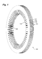
Figure 1 is a perspective view of a stator core comprising stator laminations in accordance with an aspect of the present invention. -
Figure 2 is a front view of a stator to which embodiments of the present invention relate. -
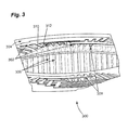
Figure 3 is a perspective view of a portion of an endcap assembly disposed within a substrate to which embodiments of the present invention relate. -
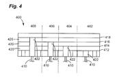
Figure 4 is a side view of an endcap assembly to which embodiments of the present invention relate -
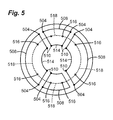
Figure 5 is a top view of an endcap assembly to which embodiments of the present invention relate. -
Figure 6 is a perspective view of an endcap assembly attached to a stator. -
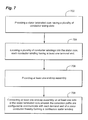
Figure 7 is a flow chart describing a step-wise method in accordance with a further embodiment of the present invention. -
Figure 8 is a diagram showing exploded view a stator and endcap assemblies. - Like reference characters designate identical or corresponding components and units throughout the several views, which are not to scale unless otherwise indicated.
- One embodiment of the present invention involves an endcap assembly which comprises a substrate and a plurality of connection paths each intervening between each turn of a stator winding, which in turn, allows for electrical communication between the connection paths and the terminal ends of the stator conductor. Two particular advantages afforded by this invention is the ability to manufacture stator cores using substantially less superfluous conduction material (e.g., magnet wire) in the endturns of a stator, and the ability to allow for a single endcap assembly to be used with a myriad of different stator conductor configurations, each of which may be applicable to a number of different stator design requirements.
- Specific configurations and arrangements of the claimed invention, discussed below with reference to the accompanying drawings, are for illustrative purposes only. Other configurations and arrangements that are within the purview of a skilled artisan can be made, used, or sold without departing from the spirit and scope of the appended claims. For example, while some embodiments of the invention are herein described with reference to an electric motor, a skilled artisan will recognize that embodiments of the invention can be implemented in any setting in which acute electrical turns are desirable.
- As used herein, an element or function recited in the singular and proceeded with the word "a" or "an" should be understood as not excluding plural said elements or functions, unless such exclusion is explicitly recited. Furthermore, references to "one embodiment" of the claimed invention should not be interpreted as excluding the existence of additional embodiments that also incorporate the recited features
- Referring now to
Figure 1 , in accordance with aspect of the present invention, a stator laminated core is shown generally at 100. The laminatedcore 100 may comprise a plurality ofstator laminations 102, and may optionally comprise statorinner vent laminations 104, and statorouter vent laminations 106. It will be appreciated that the laminatedcore 100 may be employed together with the laminated core 10 in e.g., a motor. Also, it will be understood that, optionally, either of the laminatedcores 10 and 100 may be employed separately in, e.g., a motor frame. - The stator laminated core may comprise
conductor wiring slots 108 disposed between conductor wiring teeth 110. The stator lamination core may be configured to accommodate at least one embedded conductor in the form of conductor windings (not shown). - Referring now to
Figure 2 , a completed stator is shown generally at 200. The completedstator 200 comprises astator core 202,stator conductors endcap assemblies - The
stator core 202 may be manufactured from e.g., steel, iron and the like. The stator core may be dimensioned to correspond to a plurality of motor sizes, and may be configured to reduce hysteresis and eddy current loss. - The
stator conductors 204 may be manufactured from any conductive material, e.g., copper or aluminum. The conductors may be further electrically isolated from the iron core by, e.g., insulating paper. The stator conductors, when coupled to the stator end cap assemblies, allow for a closed circuit electrical path and, in turn, the production of a magnetic field when current is passed therethrough. In an embodiment of the present invention, the conductors may be formed into a predetermined arrangement in a stator slot, allowing a uniform, stacked, layered formation. However, in an optional embodiment, the conductors may be positioned in a random orientation, in which the conductors are randomly arranged in a stator slot. In yet another optional embodiment of the present invention, the formed or randomly arranged conductors may be precoupled to at least one endcap on one side of the stator and inserted into stator core, e.g., via an injection mechanism. The endcap assemblies 208 and 210 may attach at the terminal ends of the stator conductors. - The
endcap assemblies Figures 3 and4 , may be attached at a first and second end of thestator 200 and may be dimensioned to correspond to a first and second end of thestator 200. In an embodiment of the present invention, the endcap assemblies may be configured to electrically communicate with the terminal ends of thestator conductors 204, thereby forming a closed electrical circuit. - Now with reference to
Figure 3 , an exemplary endcap assembly is shown generally at 300 and comprises a plurality ofconnection paths 302,substrate 304, a plurality ofstator conductors 306 andconnection joints 308. - In an exemplary embodiment of the present invention, the
connection paths 302 may be manufactured of a conductive material such as copper or aluminum. The plurality ofconnection paths 302 may each be intervening between each turn of the stator winding, which comprise a plurality of conductors, at 310. In turn, each connection path may be configured to communicate with each terminal end of thestator conductor 306. In other words, the connection paths may be aligned with the terminal ends of the stator conductors to complete a closed loop circuit. - With further reference to
Figure 3 , thedielectric material 304, may be a substrate manufactured from e.g., FR4, N5000 BT, or 33N or coated with, e.g., parylene to provide an insulating channel between the connection paths and their environment. Thedielectric material 304, in effect, may act as a housing for theinternal connection paths 302 and the terminal ends of the stator conductors that may reside there. The dialectic material may also provide stiffness necessary in a multitude of electrical design configurations. In an optional embodiment, an encapsulate may be provided as a dielectric material. The encapsulate may be an epoxy resin suitable in electrical applications. In a further optional embodiment of the present invention, the dielectric material may comprise an outer periphery surface configured to protect each endcap assembly on the stators outermost sides. - At
connection point 312, the connection paths may reside in a plane that approximately orthogonal to a longitudinal axis of eachstator conductor 306, while further residing circumferentially along an inner surface of thedielectric material 304. In optional embodiments of the present invention, the connection paths may be configured in a layered formation as required by motor performance design, which will be discussed in greater detail with reference toFigure 4 . Theconnection point 312 may further comprise a bonding portion (not shown) where the electrical connection between the connection paths and the stator conductors are made. The bonding portion may comprise any advantageous connection assembly, e.g., a braze joint, a solder joint, a spring clip, a compression pin, a bolted connection, contacts, friction stir welds, and the like. - Referring now to
Figure 4 , a side view of an endcap assembly is shown generally at 400. The endcap assembly may be configured in a layered formation. By "layered" is meant that connection paths may reside in separate planes circumferentially around the endcap. Also, there may be intervening layers of dielectric insulating material to both insulate each connection path and provide support for the connection paths as well. This exemplary endcap embodiment allows for a single endcap to be used with a myriad of different stator conductor configurations, each of which may be applicable to a number of different stator design requirements. For example, in a firstoptional embodiment 402, thestator conductors 410 may connect at a firsttier connection path 412. In otheroptional embodiments connection paths bonding portions 422. Intervening layers of adielectric material 420, e.g., a substrate or epoxy resin encapsulate, may be layered between each layered connection path to electrically isolate each connection path. - In another embodiment of the present invention, the endcap assembly may comprise a heavy copper printed circuit board.
Figures 5 shows a top view of an endcapassembly comprising traces 504 that may etched or plated onto a substrate 502, e.g., heavy copper. Heavy copper may comprise any circuit with a copper weight in excess of 4oz./ft2. The traces may be light copper and interlinked with heavy copper tracks. The substrate may cylindrically dimensioned and comprise a middle aperture 520, the size and shape of which may be predetermined to correspond to stator design requirements. - In this exemplary embodiment of the present invention, the circuit board may be layered, and thus may comprise
external traces 504, connected vialine 508, andinternal traces 510 connected vialine 514. While, as shown, the exemplary circuit is a two-layer circuit board, it is to be appreciated that a plurality of layers may be envisioned to match a plurality of stator conductor and motor configurations. For example, the endcap may includeinternal traces 516 connected vialine 518 disposed circumferentially around the endcap, in a plane that is below the internal traces 510. Furthermore, the endcap may include cotraces (not shown) for making electrical connections from layer to layer. This exemplary arrangement may also allow for a single endcap to be used with a myriad of different stator conductor configurations, each of which may be applicable to a number of different stator design requirements. - It is to be appreciated that each embodiment of the stator core and endcap assembly may further comprise a connector for insertion of an external power source (not shown) for providing power to the stator.
- Referring now to
Figure 6 , a perspective view of an endcap assembly attached to a stator is shown generally at 600 to more clearly illustrate the present invention. In this embodiment of the present invention, the stator assembly comprisesconnection paths 602,dielectric material 604, stator conductors 606, andstator frame 608. Theconnection paths 602 together with bonding portions (not shown) may permit an approximately 90 degree electrical connection between the each stator conductor 606, and therefore in each stator winding thereby substantially reducing the amount of stator conductor material necessary to form a complete stator winding for a closed circuit. Furthermore, this embodiment of the present invention houses the endtums of the stator thereby substantially decreases damage at the endtums. In an optional embodiment of the present invention, theconnection paths 602 may be oriented in a plane that is angled or arched with respect to other connection paths thereby preventing separate electrical paths from contacting one another. - Referring now to
Figure 7 , a method for making a stator for an electric motor is provided generally at 700. The flowchart is shown to better help illustrate this exemplary method. While the flowchart shows an exemplary step-by-step method, it is to be appreciated that a skilled artisan may rearrange or reorder the steps while maintaining like results. - Providing a stator laminated core having a plurality of
conductor winding posts 702 may comprise a combination of stator laminations, such as those shown inFigure 1 . The stator laminated core may be formed by stacking a plurality of stator laminations to form a core, each held together via cleats, staples, welds, and the like. On the inner circumferential surface of the core there may be a plurality of stator teeth mounted to the core. The stator teeth may comprise winding slots, which may be dimensioned to correspond to stator conductor wires. - Locating a plurality of conductor windings into the stator core, each conductor winding have at least one
terminal end 704 may comprise providing formed individual rectangle wires dimensioned to correspond to winding slots in a stator core, allowing for a uniform, stacked, layered formation. However, in an optional embodiment, the conductors may be positioned randomly, in which the conductors are randomly arranged within the stator slot. In yet another optional embodiment of the present invention, the formed or randomly arranged conductors may be precoupled to at least one endcap and then be inserted into the stator core post-production via auto-injection. - Each of the conductor windings may have at least one terminal end. What is meant by "terminal end" is that each of the conductor windings comprises an end portion wherein the winding is incomplete until the addition of an endcap assembly, which may then complete the conductor winding and form a closed loop circuit. Forming a terminal end may comprise cutting or stripping the completed windings at their outermost periphery, or inserting or injecting wires into the core that have been preformed to comprise a terminal end. The terminal end of each conductor winding may extend outside of the frame as shown in
Figure 8 at 800. In this exemplary embodiment, the windings comprise two terminal ends 804 and 806, each being configured with the ability to electrically communicate with the endcap assemblies that will be attached thereto. Therefore, the terminal ends may be spaced to correspond to the plurality of connection paths of the endcap assemblies, which may in turn correspond to a plurality of winding and stator arrangements. To provide for a more simple endcap attachment, the terminal ends of the windings may be color coated to correspond to the appropriate point of attachment at an endcap, which will depend upon the winding arrangements and stator design. Other suitable methods for matching particular attachment points may include a crimped shapings on the end of the wire, e.g., a triangle, diamond, etc. - Providing at least one endcap assembly, the endcap assembly comprising a substrate and a plurality of connection paths each being supported by the substrate and each intervening between each turn of the stator winding and wherein the connection paths are configured to communicate with each terminal end of a
stator conductor 706 may comprise, for example as shown inFigure 8 , attachment at each end of the stator, as shown by arrows 812 and 814. - Connecting the at least one endcap assembly on at least one side of the stator core, wherein the connection paths are configured to communicate with each terminal end of a stator conductor thereby forming a continuous conductor winding 708 may comprise attachment via braze joints, a solder joints, spring clips, compression pins, bolted connections, contacts, friction stir welds, and the like.
- When the endcap assemblies are attached, the terminal ends of the stator conductors and the endcap assembly connection paths connect to form a closed circuit, and complete the stator windings, as shown in
Figure 3 . It is thus advantageous to manufacture a substrate made of a dielectric material and is dimensioned to correspond with the ends of particular stator. - Although specific features of various embodiments of the invention may be shown in some drawings and not in others, this is for convenience only. In accordance with the principles of the invention, the feature(s) of one drawing may be combined with any or all of the features in any of the other drawings. The words "including", "comprising", "having", and "with" as used herein are to be interpreted broadly and comprehensively and are not limited to any physical interconnection. Moreover, any embodiments disclosed herein are not to be interpreted as the only possible embodiments. Rather, modifications and other embodiments are intended to be included within the scope of the appended claims.
Claims (15)
- An endcap assembly (208, 210) for a stator (200) of an electric motor comprising a stator winding, the endcap assembly comprising:a dielectric material (304); anda plurality of connection paths (302) each being supported by the dielectric material (304) and each intervening between each turn of the stator winding and wherein the connection paths (302) are configured to communicate with each terminal end (804, 806) of a stator conductor (306).
- The endcap assembly of claim 1, wherein the stator winding comprises a plurality of conductors (306) and wherein each connection path (302) resides in a plane that is approximately orthogonal to a longitudinal axis of each conductor (306).
- The endcap assembly of claim 1 or claim 2, wherein the dielectric material (304) is a substrate or an epoxy, and wherein the dielectric material is intervening between a plurality of layers of connection paths (302).
- The endcap assembly of any one of the preceding claims, wherein the endcap assembly (208, 210) comprises two endcap assemblies (208, 210), each dimensioned to correspond to a first and second end of a stator (200).
- The endcap assembly of any one of the preceding claims, wherein the connection paths comprise copper or aluminum.
- The endcap assembly of any one of the preceding claims, wherein the connection path comprises a plurality of connection paths (302) that reside circumferentially along an inner or outer surface of the dielectric material (304) and further reside in separate planes.
- The endcap assembly of any one of the preceding claims, further comprising connection joints (308) having a bonding portion, the bonding portion configured to electrically connect the connection paths (302) to each of the terminal ends (804, 806) of the stator conductor.
- The endcap assembly of any one of the preceding claims, wherein the connection joint comprises a braze joint, a solder joint, a spring clip, a compression pin, a bolted connection, contacts, or friction stir welds.
- A method of making a stator (200) for an electric motor comprising:providing a stator core (100) having a plurality of conductor winding slots (108);locating a plurality of conductor windings into the stator core, each conductor winding have at least one terminal end (804, 806);providing at least one endcap assembly (208, 210), the endcap assembly comprising:a dielectric material (304); anda plurality of connection paths (302) each being supported by the dielectric material (304) and each intervening between each turn of the stator winding;connecting the at least one endcap assembly (208, 210) at a first and second side of the stator core (100), wherein the connection paths (302) are configured to communicate with each terminal end (804, 806) of a stator conductor thereby forming a continuous conductor winding.
- The method of claim 9, wherein the stator winding comprises a plurality of conductors (706) and wherein each connection path (302) resides in a plane that is approximately orthogonal to a longitudinal axis of each conductor (706).
- The method of claim 9 or claim 10, wherein the dielectric material (304) is a substrate or an epoxy and wherein the dielectric material is intervening between a plurality of layers of connection paths (302).
- The method of any one of the preceding claims, wherein the endcap assembly comprises two or more endcap assemblies, each dimensioned to correspond to a first and second end of a stator.
- The method of any one of claims 9 to 12, wherein the connection path (302) comprises a plurality of connection paths that reside circumferentially along a surface of the dielectric material (304).
- The method of any one of claims 9 to 13, further comprising connection joints having a bonding portion, the bonding portion configured to electrically connect the connection paths to each of the terminal ends of the stator conductor.
- The method of any one of claims 9 to 14, wherein the connection joint comprises a braze joint, a solder joint, a spring clip, a compression pin, a bolted connection, contacts, or friction stir welds.
Applications Claiming Priority (1)
| Application Number | Priority Date | Filing Date | Title |
|---|---|---|---|
| US12/190,197 US20100038988A1 (en) | 2008-08-12 | 2008-08-12 | Stator and Method of Making the Same |
Publications (1)
| Publication Number | Publication Date |
|---|---|
| EP2154768A2 true EP2154768A2 (en) | 2010-02-17 |
Family
ID=41429715
Family Applications (1)
| Application Number | Title | Priority Date | Filing Date |
|---|---|---|---|
| EP09166914A Withdrawn EP2154768A2 (en) | 2008-08-12 | 2009-07-31 | A stator and method of making the same |
Country Status (6)
| Country | Link |
|---|---|
| US (1) | US20100038988A1 (en) |
| EP (1) | EP2154768A2 (en) |
| KR (1) | KR20100020439A (en) |
| CN (1) | CN101651378A (en) |
| CA (1) | CA2674387A1 (en) |
| MX (1) | MX2009008512A (en) |
Cited By (3)
| Publication number | Priority date | Publication date | Assignee | Title |
|---|---|---|---|---|
| EP3128650A1 (en) * | 2015-08-04 | 2017-02-08 | Alber GmbH | Direct current machine and method for producing a direct current machine |
| US10461598B2 (en) | 2015-08-04 | 2019-10-29 | Alber Gmbh | Direct current machine and method for manufacturing a direct current machine |
| EP4113800A1 (en) * | 2021-07-02 | 2023-01-04 | Hamilton Sundstrand Corporation | Pcb connector |
Families Citing this family (18)
| Publication number | Priority date | Publication date | Assignee | Title |
|---|---|---|---|---|
| CA2822059A1 (en) | 2010-12-16 | 2012-06-21 | Vertex Pharmaceuticals Incorporated | Inhibitors of influenza viruses replication |
| CN103562205A (en) | 2010-12-16 | 2014-02-05 | 沃泰克斯药物股份有限公司 | Inhibitors of influenza viruses replication |
| CN102545486B (en) * | 2010-12-23 | 2015-08-19 | 奇鋐科技股份有限公司 | Motor waterproof structure manufacturing method |
| KR102023012B1 (en) * | 2013-04-05 | 2019-09-19 | 엘지전자 주식회사 | stator and a electrical rotating device including the same |
| DE102014007549A1 (en) * | 2014-05-22 | 2015-11-26 | Audi Ag | Electric machine |
| KR20170027385A (en) | 2015-09-02 | 2017-03-10 | 에스에스에이 주식회사 | Motor stator automatic assembly apparatus and method |
| DE102015220112A1 (en) * | 2015-10-15 | 2017-04-20 | Continental Automotive Gmbh | Electric machine comprising a stator with reduced winding overhang |
| CN105762947B (en) * | 2016-04-29 | 2017-06-27 | 上海浦赛动力科技有限公司 | Armature, end module for armature and method for assembling an armature |
| CN106329744A (en) * | 2016-08-29 | 2017-01-11 | 北京交通大学 | Motor structure based on transverse H-shaped sectional ventilating channel steel |
| EP3364524A1 (en) * | 2017-02-21 | 2018-08-22 | Siemens Aktiengesellschaft | Stator for electric machine |
| JP6416959B2 (en) * | 2017-03-15 | 2018-10-31 | 本田技研工業株式会社 | Electrical conductor joining method |
| CN111164857B (en) * | 2017-06-20 | 2022-11-01 | 格劳博-沃克有限责任两合公司 | Method and device for inserting electrical conductors in machine parts of electrical machines |
| DE102018101231A1 (en) * | 2018-01-19 | 2019-07-25 | Brusa Elektronik Ag | Stator for an electric machine and method for its production |
| EP3627671A1 (en) * | 2018-09-21 | 2020-03-25 | Siemens Aktiengesellschaft | Method for producing a winding head assembly for an electric rotating machine |
| US20210031297A1 (en) * | 2019-08-01 | 2021-02-04 | GM Global Technology Operations LLC | System and method for multi-task laser welding |
| DE102020111704A1 (en) * | 2020-04-29 | 2021-11-04 | Molabo Gmbh | Stator for an electrical machine and method for producing a stator for an electrical machine |
| WO2023015667A1 (en) * | 2021-08-09 | 2023-02-16 | 浙江盘毂动力科技有限公司 | Circuit board unit, winding stator structure, stator assembly, disc motor, and assembly method |
| CN113595300B (en) * | 2021-08-09 | 2022-11-22 | 浙江盘毂动力科技有限公司 | Circuit board of integrated stator winding gap bridge wire |
Citations (3)
| Publication number | Priority date | Publication date | Assignee | Title |
|---|---|---|---|---|
| JP2001037131A (en) | 1999-07-15 | 2001-02-09 | Mitsubishi Electric Corp | AC generator for vehicles |
| JP3196738B2 (en) | 1998-09-11 | 2001-08-06 | 株式会社デンソー | Stator manufacturing apparatus and stator manufacturing method |
| US6548933B2 (en) | 2000-01-31 | 2003-04-15 | Hitachi, Ltd. | Stator of rotating electric machine |
Family Cites Families (10)
| Publication number | Priority date | Publication date | Assignee | Title |
|---|---|---|---|---|
| US2407935A (en) * | 1944-05-25 | 1946-09-17 | Chrysler Corp | Electrical machine |
| US4321497A (en) * | 1980-04-10 | 1982-03-23 | Westinghouse Electric Corp. | Peripheral connector ring stator end winding for dynamoelectric machines |
| JP2000270506A (en) * | 1999-03-19 | 2000-09-29 | Honda Motor Co Ltd | Motor stator structure |
| US6538356B1 (en) * | 2000-06-28 | 2003-03-25 | Robert M. Jones | Electric machine using composite blade structure |
| EP1366557B1 (en) * | 2001-03-09 | 2009-12-02 | TEMIC Automotive Electric Motors GmbH | Winding structure for an electrical machine and method for producing the same |
| JP3613262B2 (en) * | 2002-04-26 | 2005-01-26 | 三菱電機株式会社 | Rotating electric machine and manufacturing method thereof |
| JP4001040B2 (en) * | 2003-03-28 | 2007-10-31 | 株式会社デンソー | Rotating electric machine stator |
| WO2004114502A1 (en) * | 2003-06-20 | 2004-12-29 | Siemens Aktiengesellschaft | Electric machine comprising a circuit support |
| US7582999B2 (en) * | 2003-11-20 | 2009-09-01 | Intelligent Electric Motor Solutions Pty Ltd | Electric machine having a magnetically inducible core |
| US6958561B2 (en) * | 2004-02-27 | 2005-10-25 | Unique Product & Design Co., Ltd. | Stator winding structure of a motor or a generator |
-
2008
- 2008-08-12 US US12/190,197 patent/US20100038988A1/en not_active Abandoned
-
2009
- 2009-07-30 CA CA2674387A patent/CA2674387A1/en not_active Abandoned
- 2009-07-31 EP EP09166914A patent/EP2154768A2/en not_active Withdrawn
- 2009-08-07 MX MX2009008512A patent/MX2009008512A/en not_active Application Discontinuation
- 2009-08-11 KR KR1020090073937A patent/KR20100020439A/en not_active Withdrawn
- 2009-08-12 CN CN200910166497A patent/CN101651378A/en active Pending
Patent Citations (3)
| Publication number | Priority date | Publication date | Assignee | Title |
|---|---|---|---|---|
| JP3196738B2 (en) | 1998-09-11 | 2001-08-06 | 株式会社デンソー | Stator manufacturing apparatus and stator manufacturing method |
| JP2001037131A (en) | 1999-07-15 | 2001-02-09 | Mitsubishi Electric Corp | AC generator for vehicles |
| US6548933B2 (en) | 2000-01-31 | 2003-04-15 | Hitachi, Ltd. | Stator of rotating electric machine |
Cited By (4)
| Publication number | Priority date | Publication date | Assignee | Title |
|---|---|---|---|---|
| EP3128650A1 (en) * | 2015-08-04 | 2017-02-08 | Alber GmbH | Direct current machine and method for producing a direct current machine |
| US10461598B2 (en) | 2015-08-04 | 2019-10-29 | Alber Gmbh | Direct current machine and method for manufacturing a direct current machine |
| EP4113800A1 (en) * | 2021-07-02 | 2023-01-04 | Hamilton Sundstrand Corporation | Pcb connector |
| US12451746B2 (en) | 2021-07-02 | 2025-10-21 | Hamilton Sundstrand Corporation | PCB connector |
Also Published As
| Publication number | Publication date |
|---|---|
| CN101651378A (en) | 2010-02-17 |
| CA2674387A1 (en) | 2010-02-12 |
| MX2009008512A (en) | 2010-03-22 |
| US20100038988A1 (en) | 2010-02-18 |
| KR20100020439A (en) | 2010-02-22 |
Similar Documents
| Publication | Publication Date | Title |
|---|---|---|
| EP2154768A2 (en) | A stator and method of making the same | |
| US20030214190A1 (en) | Connection device for hairpin wound electric machines | |
| US4039875A (en) | Method and apparatus for interconnecting stator coils | |
| CN112075012B (en) | electromagnetic device | |
| KR20180090788A (en) | Segment Brushless Stator Interconnect System | |
| CN1862925B (en) | Method for winding the stator of an electric motor, and stator for an electric motor | |
| CN105103415A (en) | Motor stator and method for manufacturing same | |
| CN100364213C (en) | Method of connecting the phases of a segmented stator motor | |
| US20220224191A1 (en) | Electric motor with injection moulded stator | |
| JP2008514173A (en) | Permanent magnet synchronous machine with rectangular wire winding | |
| TW201431252A (en) | Axial flow fan | |
| JPH11251164A (en) | Compact choke coil | |
| US8269386B2 (en) | Phase lead connections for a bar wound stator | |
| US7417342B2 (en) | Holder for winding wires for stators of electric motors | |
| US9236782B2 (en) | Motor stator automatically assembling method | |
| EP2096649A2 (en) | Alpha-turn coil | |
| US20040100157A1 (en) | Electric machine end turn connectors | |
| GB2606896A (en) | A field coil for an electric machine | |
| US20140300226A1 (en) | Motor Stator Manufacturing Method and Structure Thereof | |
| JP2000217291A (en) | Low voltage electric machine stator | |
| JP4259305B2 (en) | AC generator for vehicle and manufacturing method thereof | |
| JPH09219959A (en) | Electric motor stator | |
| KR20140028967A (en) | The stator for motor | |
| JPH0134281Y2 (en) | ||
| KR20250014926A (en) | Stator assembly with insulation structure |
Legal Events
| Date | Code | Title | Description |
|---|---|---|---|
| PUAI | Public reference made under article 153(3) epc to a published international application that has entered the european phase |
Free format text: ORIGINAL CODE: 0009012 |
|
| AK | Designated contracting states |
Kind code of ref document: A2 Designated state(s): AT BE BG CH CY CZ DE DK EE ES FI FR GB GR HR HU IE IS IT LI LT LU LV MC MK MT NL NO PL PT RO SE SI SK SM TR |
|
| AX | Request for extension of the european patent |
Extension state: AL BA RS |
|
| STAA | Information on the status of an ep patent application or granted ep patent |
Free format text: STATUS: THE APPLICATION IS DEEMED TO BE WITHDRAWN |
|
| 18D | Application deemed to be withdrawn |
Effective date: 20130201 |