EP2154656A2 - Photogène - Google Patents
Photogène Download PDFInfo
- Publication number
- EP2154656A2 EP2154656A2 EP09010335A EP09010335A EP2154656A2 EP 2154656 A2 EP2154656 A2 EP 2154656A2 EP 09010335 A EP09010335 A EP 09010335A EP 09010335 A EP09010335 A EP 09010335A EP 2154656 A2 EP2154656 A2 EP 2154656A2
- Authority
- EP
- European Patent Office
- Prior art keywords
- transaction data
- server
- token
- client
- authentication
- Prior art date
- Legal status (The legal status is an assumption and is not a legal conclusion. Google has not performed a legal analysis and makes no representation as to the accuracy of the status listed.)
- Ceased
Links
Images


Classifications
-
- H—ELECTRICITY
- H04—ELECTRIC COMMUNICATION TECHNIQUE
- H04L—TRANSMISSION OF DIGITAL INFORMATION, e.g. TELEGRAPHIC COMMUNICATION
- H04L63/00—Network architectures or network communication protocols for network security
- H04L63/08—Network architectures or network communication protocols for network security for authentication of entities
- H04L63/0853—Network architectures or network communication protocols for network security for authentication of entities using an additional device, e.g. smartcard, SIM or a different communication terminal
-
- G—PHYSICS
- G06—COMPUTING; CALCULATING OR COUNTING
- G06Q—INFORMATION AND COMMUNICATION TECHNOLOGY [ICT] SPECIALLY ADAPTED FOR ADMINISTRATIVE, COMMERCIAL, FINANCIAL, MANAGERIAL OR SUPERVISORY PURPOSES; SYSTEMS OR METHODS SPECIALLY ADAPTED FOR ADMINISTRATIVE, COMMERCIAL, FINANCIAL, MANAGERIAL OR SUPERVISORY PURPOSES, NOT OTHERWISE PROVIDED FOR
- G06Q20/00—Payment architectures, schemes or protocols
- G06Q20/08—Payment architectures
- G06Q20/10—Payment architectures specially adapted for electronic funds transfer [EFT] systems; specially adapted for home banking systems
-
- G—PHYSICS
- G06—COMPUTING; CALCULATING OR COUNTING
- G06Q—INFORMATION AND COMMUNICATION TECHNOLOGY [ICT] SPECIALLY ADAPTED FOR ADMINISTRATIVE, COMMERCIAL, FINANCIAL, MANAGERIAL OR SUPERVISORY PURPOSES; SYSTEMS OR METHODS SPECIALLY ADAPTED FOR ADMINISTRATIVE, COMMERCIAL, FINANCIAL, MANAGERIAL OR SUPERVISORY PURPOSES, NOT OTHERWISE PROVIDED FOR
- G06Q20/00—Payment architectures, schemes or protocols
- G06Q20/30—Payment architectures, schemes or protocols characterised by the use of specific devices or networks
- G06Q20/34—Payment architectures, schemes or protocols characterised by the use of specific devices or networks using cards, e.g. integrated circuit [IC] cards or magnetic cards
- G06Q20/341—Active cards, i.e. cards including their own processing means, e.g. including an IC or chip
-
- G—PHYSICS
- G06—COMPUTING; CALCULATING OR COUNTING
- G06Q—INFORMATION AND COMMUNICATION TECHNOLOGY [ICT] SPECIALLY ADAPTED FOR ADMINISTRATIVE, COMMERCIAL, FINANCIAL, MANAGERIAL OR SUPERVISORY PURPOSES; SYSTEMS OR METHODS SPECIALLY ADAPTED FOR ADMINISTRATIVE, COMMERCIAL, FINANCIAL, MANAGERIAL OR SUPERVISORY PURPOSES, NOT OTHERWISE PROVIDED FOR
- G06Q20/00—Payment architectures, schemes or protocols
- G06Q20/38—Payment protocols; Details thereof
- G06Q20/40—Authorisation, e.g. identification of payer or payee, verification of customer or shop credentials; Review and approval of payers, e.g. check credit lines or negative lists
- G06Q20/403—Solvency checks
- G06Q20/4037—Remote solvency checks
-
- H—ELECTRICITY
- H04—ELECTRIC COMMUNICATION TECHNIQUE
- H04L—TRANSMISSION OF DIGITAL INFORMATION, e.g. TELEGRAPHIC COMMUNICATION
- H04L9/00—Cryptographic mechanisms or cryptographic arrangements for secret or secure communications; Network security protocols
- H04L9/32—Cryptographic mechanisms or cryptographic arrangements for secret or secure communications; Network security protocols including means for verifying the identity or authority of a user of the system or for message authentication, e.g. authorization, entity authentication, data integrity or data verification, non-repudiation, key authentication or verification of credentials
- H04L9/3234—Cryptographic mechanisms or cryptographic arrangements for secret or secure communications; Network security protocols including means for verifying the identity or authority of a user of the system or for message authentication, e.g. authorization, entity authentication, data integrity or data verification, non-repudiation, key authentication or verification of credentials involving additional secure or trusted devices, e.g. TPM, smartcard, USB or software token
-
- H—ELECTRICITY
- H04—ELECTRIC COMMUNICATION TECHNIQUE
- H04L—TRANSMISSION OF DIGITAL INFORMATION, e.g. TELEGRAPHIC COMMUNICATION
- H04L2209/00—Additional information or applications relating to cryptographic mechanisms or cryptographic arrangements for secret or secure communication H04L9/00
- H04L2209/56—Financial cryptography, e.g. electronic payment or e-cash
-
- H—ELECTRICITY
- H04—ELECTRIC COMMUNICATION TECHNIQUE
- H04L—TRANSMISSION OF DIGITAL INFORMATION, e.g. TELEGRAPHIC COMMUNICATION
- H04L2209/00—Additional information or applications relating to cryptographic mechanisms or cryptographic arrangements for secret or secure communication H04L9/00
- H04L2209/80—Wireless
- H04L2209/805—Lightweight hardware, e.g. radio-frequency identification [RFID] or sensor
Definitions
- the invention relates to the technical field of authentication of transactions, for. As bank transfers, via a communication network, eg. As the Internet, local networks or mobile networks.
- a communication network eg. As the Internet, local networks or mobile networks.
- the customer provides via a communication device or via a client, for example a home computer, which is connected to a bank server via a computer network, transaction data which are transmitted from the communication device to the bank server via the communication network.
- This transaction data includes sensitive information such as recipient data of an electronic money order or the amount to be transferred.
- Today's communication networks allow, through a variety of cryptographic methods, data to be transmitted securely over the channels of the communication network.
- the transaction data Upon receipt of the transaction data by the bank server, the transaction data must be authenticated by the server. Authentication means the respective process of proving the authenticity of the transaction data by a suitable method. In other words, one checks at the Authentication, whether the transaction data are "authentic", that is unadulterated.
- One method is e.g. in giving the customer a password or a PIN, which must be transmitted together with the transaction data to the bank server.
- the transaction data is then considered authentic, i. as authenticated if the customer can provide the "correct" password to submit the transaction data.
- the security of this procedure against abuse can be compromised if the PIN could not be kept secret.
- the prior art has addressed this problem and provided so-called PIN / TAN methods.
- the TANs are transaction numbers which are also known to the person skilled in the art under the term OTP (one-time password).
- OTP one-time password
- a higher level of security is achieved in this authentication method in that the transaction data (together with the PIN) are associated with a "secret", ie with a knowledge of the transaction number, this transaction number is used only once for authentication.
- a potential interceptor can do so by listening to the PIN together with the TAN only a single time damage. This is an advantage over the traditional PIN method, since there the listener could, at least theoretically, by doing unauthorized use of the intercepted password several times cause damage.
- the PIN / TAN process as a specific form of the OTP process, where the TAN is considered to be OTP, still has a number of disadvantages.
- a significant disadvantage is the fact that the customer in a cumbersome way, e.g. by post, the respective required TAN or a list of TANs must be delivered.
- An electronic solution shows eg the DE 100 45 924 ,
- the TAN if required by the customer, loaded on the mobile phone, this mobile phone must be previously registered for this electronic TAN procedure.
- a common variant of the man-in-the-middle attack is to place so-called Trojan software on the communication device, e.g. the client's home computer.
- the uploaded Trojan software may e.g. implement a "key logging" in which the customer's keyboard connected to the home computer is intercepted.
- the transaction data entered via the keyboard can then be registered by the Trojan software as a sequence of character strings, so that the listener can issue a "non-authentic" payment instruction, by changing at least the recipient, by using these intercepted strings.
- an identifier is simultaneously displayed on an additional, secure display and in the document to be signed.
- the identifier is generated by an external server and differs from the document. If the two identifiers are displayed, it is ensured that the signing relates precisely to this document. Manipulations in which the listener attempts to direct the signing to a manipulated version of the document to be signed are thus made more difficult for the listener.
- a safe display is generally also a device or a sub-component referred to, in which the data display is made tamper-proof, so that the user is fooled at any time by fake display data.
- the EP 1211841 discloses to display the data to be signed before signing on an additional secure, alphanumeric display for control, wherein the data to be signed are transmitted by a sensor to the additional display. This ensures that only the document displayed on the additional secure display is signed, ie that the signing process relates exactly to the document displayed in the secure display.
- the electronic transaction may be an electronic money order within the framework of so-called "Internet Banking” or "Mobile Banking”.
- the transaction data comprise, in electronic form, a PIN uniquely assigned to the user, in addition also user data, i. Sender data, in particular bank connection data of the user, recipient data, in particular bank connection data of a recipient of the payment instruction, and amount data, e.g. Purpose and an amount of the amount to be paid.
- user data i. Sender data, in particular bank connection data of the user, recipient data, in particular bank connection data of a recipient of the payment instruction, and amount data, e.g. Purpose and an amount of the amount to be paid.
- the method according to the invention is a so-called two-factor authentication method by which, based on two factors, it is to be ensured that the transaction data for the execution of the electronic transaction are actually issued by the user and therefore "authentic " are.
- the one factor is going through the transaction data is formed while the other factor is formed by the authentication feature generated according to the invention based on the transaction data.
- the authentication method is an identity check of the transaction data to ensure the identity of the user, the identity being expressed by the sender data in the transaction data.
- the method assumes that the user, via the client, generally a conventional home computer, or a mobile, personal digital assistant (PDA), via a network, e.g. the Internet, with the server, preferably a central bank server, can communicate.
- a network e.g. the Internet
- the server preferably a central bank server
- the user builds e.g. via a running on the client browser software to connect to the bank server for the purpose of executing the transaction.
- the user is then prompted by the server via the input mask displayed on the client to enter the transaction data.
- client in particular the entirety of the components required for communication with the server, i. in particular a display for displaying the input mask, a keyboard for entering the transaction data and a computer unit, portable or stationary, with the appropriate software and interfaces that are necessary for communication with the server.
- the method according to the invention provides that, in addition to the transaction data just transmitted, a digital form of a representation of the separate transaction data represented on the input mask is transmitted as the authentication feature from a device, the token, to the server at a later point in time.
- the exact time of transmission of the authentication feature is arbitrary and can be specified by the bank server by a predefined period of time.
- the representation ie a pictorial or other representation of the input mask (browser window) with the entered transaction data
- Plaintext representation is understood to be a user-readable mapping (in particular a reversible 1: 1 mapping) of the transaction data displayed in the input mask.
- the token is given in advance by the bank to the user.
- a software module that controls the appearance and behavior of the input mask eg a CGI script (common gateway interface)) on the bank server ensures that the transaction data are displayed on the input mask until the user has accessed the data Token has generated the authentication feature or at least until the representation of the input mask has been detected by the token.
- CGI script common gateway interface
- the token is a portable and handy device, such as a smart card or a mobile terminal, capable of communicating with the server either directly or through the client for the purpose of communicating the mapped transaction data.
- the token is designed as a separate "component", independent of the client Service.
- the token is uniquely assigned to a user. This is done via a personalization that takes place in advance.
- the token for use in the authentication method has been personalized either ad hoc for the current transaction prior to the transmission of the authentication feature, or has been personalized once for all future user-to-be-executed transactions.
- Personalization is done by a suitable personalization device, such as the user's bank or, if the token is a mobile terminal, a mobile network operator or other trusted service provider.
- a suitable personalization device such as the user's bank or, if the token is a mobile terminal, a mobile network operator or other trusted service provider.
- Personalization is the creation and management of a data set, for uniquely linking an ID of the token with the user unambiguously identifying identification data (for example, name including place of residence, etc.). Personalization data is typically stored securely and protected against misuse and counterfeiting in the token. This can be supported by using cryptography and / or hardware protection elements.
- the bank server can assume on receipt of the authentication feature with sufficient certainty that the associated transaction data was transmitted exactly by the authorized user, since the token is personalized to the user.
- the authentication method is based on two factors: First, the conventionally transmitted transaction data, and secondly by the subsequently transmitted authentication feature, which can be regarded as OTP (One Time Password) for the transaction, since it is newly created for each transaction session.
- OTP One Time Password
- the authentication method according to the invention has quite a number of advantages over the prior art.
- the authentication method is safe from listening to the keyboard by suitable Trojan software, e.g. Key logging modules that have been applied to the client by an eavesdropper.
- suitable Trojan software e.g. Key logging modules that have been applied to the client by an eavesdropper.
- the listener would also have to additionally transmit such a plain-text representation of the same transaction data to the bank server, which is not possible for the listener.
- the "real" transaction data previously transmitted by the user differs, at least with respect to the recipient data, from the non-authentic transaction data which can be deducted from the listener.
- the server can receive from all received transaction data, i. H. the authentic transaction data and possibly a number of non-authentic transactional data, by means of the authentication feature received from the personalized token, uniquely selects the transactional data issued by the user.
- the authentication feature can be locally generated by the user. For the generation of the authentication feature, no interaction is necessary, in particular with the bank server or with external sources. This gives the user a big one Flexibility in terms of technical equipment and also spatial flexibility, since the token can be used anywhere, be it on a home computer, or on a publicly accessible computer or communication device.
- the exact realization of the authentication feature as a representation or representation of the presented transaction data on the input screen is also flexible.
- it is a digitized image of the input mask with the transaction data.
- it may also be a linguistic phonetic representation.
- the user speaks the transaction data, e.g. via a microphone located on the token as a corresponding voice file on the token.
- the authentication feature With regard to the transmission of the authentication feature to the server, there is temporal flexibility, since the authentication feature as such is completely decoupled from the transaction data transmitted by the user via the client.
- the authentication feature in its digital form, whether image or voice file, can in particular be transmitted to the server at a much later time than the transaction data in order, for example, to save transmission costs.
- the server After receiving the transaction data from the client, the server remains in a wait position at which the transaction will not release until the authentication feature was determined by the user via his personalized token and received there.
- the server is set to automatically abort the transaction if, within a preset period of time, e.g. one day, the associated authentication feature is not received. This gives the user additional flexibility, since the user can cancel the transaction simply by omitting the associated authentication feature, if the user should have decided otherwise in the meantime.
- the task is also solved by another method for authenticating the transaction data based on the token, the token for implementing this method, except for a simple numerical display, not having any further output interfaces.
- This selection of the transaction data or the signal is based on a random selection, which the server applies to the received transaction data, advantageously including, in particular, the recipient data in the random selection.
- the signal sent by the server to the client in addition to visually highlighting the random selection of the transaction data, also provides a representation of the respective selected transaction data in encrypted form based on a server key.
- This representation is advantageously made on the display connected to the client in a separate window in machine-readable form, e.g.
- the encrypted selection of the transaction data shown in the window is captured as a digital image of the token and decrypted by a key stored in the token, matching the server key and displayed in this decrypted form in plain text on the display of the token for display ,
- the user then triggers by means of a trigger located on the token the automatic generation of the authentication feature via a re-encryption with a token also stored in the token, the selection of transaction data displayed on the display in plain text, if the plain text with the highlighted color selection on the Input mask matches.
- the authentication feature according to this method is a digit sequence, namely the selection of the transaction data encrypted with the token key. This selection of the transaction data encrypted with the token key is then input by the user via the keyboard into a field provided for the authentication feature in the input mask.
- the authentication feature is transmitted to the server via the client, where the received authentication feature is then decrypted with a key known to the server, corresponding to the token key, and with the selection initially generated by the server the transaction data is compared. If they match, the received transaction data is considered authenticated.
- An interface between the token and the server is formed or mediated in this method by the user who realizes the generation of the authentication feature by comparing the display on the display and a corresponding triggering of the second encryption.
- this method requires a more frequent communication requirement between client and server as compared to the method presented above and is based on a token-specific server key and a server-specific token key or a key pair of a preferably asymmetric encryption method.
- An advantage of this method is that the token does not have to have an interface to the client, or does not need to have an interface with which to connect to the server.
- the client itself can therefore be simple, especially without a USB interface.
- Another advantage of this method is that the user can enter the authentication feature in the form of the number sequence as OTP for the transaction safely on the keyboard.
- the eavesdropper can then not use the intercepted authentication feature together with the intercepted transaction data for an attack.
- the eavesdropper would have to open a new communication session with the bank server to be able to send the non-authentic transaction data together with the authentication feature to the bank server. In the course of this communication session, however, the bank server would make a new random selection from the non-authentic transaction data and thus make the intercepted authentication feature obsolete.
- the object is also achieved by a system for authenticating the transaction data requiring authentication for the electronic transaction in accordance with the enclosed main claim.
- the system includes not only the client but also the server, the server need not necessarily be the bank server, since the authentication method according to the invention can also be implemented by an external server that manages by an external service provider as a service for the bank becomes.
- the external server of the external service provider implements all essential method steps in connection with the authentication method according to the invention.
- the signal is sent to the actual bank server for executing the transaction.
- the server and the client communicate via a client interface that is adapted to receive the transaction data from the client or to receive the authentication feature from the token via the client.
- the token itself is in one embodiment designed as a mobile terminal, e.g. as a mobile phone or as a PDA (Personal Digital Assistant), wherein advantageously the mobile terminal comprises a camera unit as an optical receiving module.
- the mobile terminal comprises a camera unit with radio interface, e.g. WLAN connection, for the transmission of the collected data.
- the representation of the input mask acquired via the camera unit with the transaction data is transmitted via MMS or via its own suitable software via a mobile network or other network (WLAN, etc.) transmitted directly to the server.
- the authentication feature in the form of the digitized image of the input mask with the transaction data is additionally optionally signed and / or encrypted, the signature being via a signature key loaded in the mobile terminal, or via SIM, Secure Flash Card, Secure Element, via ARM Trust Zone or via a NFC-linked bank card.
- the system also includes a token interface via which the token communicates with the server and, in particular, transmits the authentication feature to the server.
- the token interface is provided as a Bluetooth or infrared interface (IRDA), so that the authentication feature is transmitted from the mobile terminal to the client and from there via the client interface is transmitted to the server.
- IRDA infrared interface
- the client is also equipped according to this embodiment with Bluetooth or infrared interface for receiving from the mobile terminal.
- the personalization interface of the token in the case that the token is a mobile terminal, is also designed as a Bluetooth or infrared interface, so that in this case the personalization of the mobile phone by the personalization unit via the client from which the user issues the transaction data.
- interface technologies such as Bluetooth or infrared
- Other interface technologies are also possible, such as e.g. RFID, WLAN, UMTS etc.
- the mobile terminal is replaced by a suitable program, e.g. a Java Aplet, charged by a push service OTA (Over-the-Air), whereby this load is confirmed by the user.
- a suitable program e.g. a Java Aplet
- OTA Over-the-Air
- the token is embodied as a smart card or as a USB token with a smart card, wherein the token furthermore comprises a rechargeable accumulator and a secure microprocessor unit, which is embodied as a smart card chip in the smart card.
- the battery is charged, for example, by connecting to the client via the USB interface.
- the optical receiving module is designed as a CMOS camera or as an optical sensor.
- the token may also include only a USB interface for a USB-enabled camera device.
- the personalization interface is designed as a contactless interface according to ISO 14443, as a Bluetooth interface or as an infrared interface (IRDA).
- IRDA infrared interface
- a chip card reading device is arranged on the token so that the token is personalized by a chip which the user receives from the personalization device, said chip being inserted into a chip card reading device via a slot provided for this purpose.
- the token comprises a simple numeric display in which the user can control the optical representation of the transaction data received by the optical receiving device.
- the token is designed as a very simple token and comprises only an optical sensor, a secure microprocessor unit with memory on which a key corresponding to the server key and the token key are stored. Furthermore, the simple token comprises the trigger for the encryption of the selected transaction data with the token key, and the simple numeric display for displaying the detected selection of the transaction on the input mask.
- An alternative task solution provides a storage medium which is intended to store the above-described computer-implemented method and is readable by a computer.
- FIG. 1 schematically shows a system for authenticating transaction data for an electronic transaction. The following is based on the FIG. 1 and the components described there a scenario described in relation to Internet banking applications.
- a customer referred to below as a user, would like to execute an electronic transaction in the context of Internet banking as part of an electronic payment instruction.
- the bank distributes a token 130 once to the user.
- the token is a hardware component on the basis of which the user can generate an authentication feature AM that can be assigned to the transaction data TD.
- the transaction data TD generally comprises data relating to the user (sender), data relating to the recipient of the payment instruction, and data about the amount of the payment instruction.
- the token 130 includes an optical receiver module 130c (e.g., a CMOS camera or optical sensor, e.g., photodiode, or a CCD chip), a microprocessor unit 130d having memory, e.g. in the form of a chip and a token interface 130a, which is preferably designed as a USB interface.
- the token interface enables communication of the token with a bank server 120, wherein the communication either takes place indirectly via a client 110 or its client interface 110b, or takes place directly with the bank server 120.
- the client interface 110b on the client 110 allows the communication of the client 110 with the bank server 120.
- the token interface is configured as a USB interface
- the communication with the bank server 120 would be indirect, i.e., a. H. is understood via a corresponding USB port on the client 110 together with the client interface 110b.
- the totality of these components is advantageously designed as a smart card or integrated into a smart card, so that the token 130 allows the user a maximum of local
- the user inputs the transaction data TD via a client 110, the transaction data TD being displayed on an input mask 110a.
- the input mask 110a is displayed on a monitor as an interactive graphical user interface by a browser software, the monitor being connected to the client computer 110, and the client computer 110 connecting via the browser software and the client interface 110b to the computer via a computer network 150 Bank server 120 has built.
- the input mask 110a has in particular fields for the inclusion of the transaction action data TD, wherein the interactivity and design such.
- B. functionalities and display of buttons on the input mask 110a through an input mask control module (eg CGI script) is coordinated and controlled on the server 120.
- the input mask control module communicates with the browser software as well as with an authentication module 120a on the bank server 120.
- transaction data TD Upon entry of the transaction data TD by the user, transaction data TD is communicated to the bank server 120 in the usual manner, establishing an encrypted connection (e.g., SSL over http).
- the running on the bank server 120 authentication module 120a receives the transaction data TD, which are cached by the authentication module 120a on the server 120. Since the authentication method according to the invention is a 2-factor authentication, the authentication module 120a is programmed to instantiate a waiting loop waiting to receive from the user an authentication feature AM assigned to this transaction data TD. The identity of the user takes the authentication module 120a from the transaction data TD. At this time, the authentication module 120a does not yet know if the transaction data TD is authentic, i. H. whether the sender of the transaction data TD really corresponds to the user.
- the transaction data TD which are readable as entries on the input mask 110a, are detected by the optical receiver module 130c of the token 130.
- the entire display including input mask 110a with the transaction data TD shown therein is detected as a photograph, and stored in the memory of the microprocessor unit 130d in the token 130 as a digital image (eg in a JPEG format with sufficiently high resolution).
- the transaction data TD it is also possible for the transaction data TD to be displayed in an additional display window on the display in machine-readable form, for example as a barcode or bit stream, after the user has requested this additional representation via a functionality provided on the input mask 110a.
- This additional window can be z. B. be generated by a FLASH plug-in.
- the optical receiver module 130c can also be embodied as a simple, optical sensor which also makes this transaction data TD detectable for such a simple form of the optical receiver module 130c.
- the image acquired via the optical reception module 130c can now serve as an authentication feature AM for the transaction data TD which can be read in the image and be transmitted by the user to the bank server 120.
- the token 130 must be personalized by a personalization unit 140 before being used in the authentication method proposed here.
- the personalization of the token 130 with respect to the user is done via the personalization interface 130b provided in the token 130.
- the personalization can also take place via any other suitable interface.
- the process of personalization can be done in different ways. For example, personalization could be done by the bank prior to handing the token 130 to the user, or via the personalization interface 130b, in which case the personalization process is performed by a service offered by the personalization unit 140.
- the personalization interface 130b may be, for example, an ISO 14443 interface with which the token 130 by a device for transmitting personalization data, this device z. B. at a POS (point of service) provided by a personalization unit 140 can be personalized.
- Personalization unit 140 may be either the bank or external service provider.
- personalization interface 130b is designed as a chip card reading device, on which, for example, a slot for receiving a chip card is arranged.
- This smart card contains personalization data confirming that the personalization has taken place, this personalization data being transmitted together with the authentication feature AM to the bank server 120, so that the bank server 120 can register the personalization that has taken place.
- the personalization data includes in particular a device ID of the token 130.
- the user obtains the chip card from the personalization unit 140.
- Personalization data associating a user ID with a device ID of the token 130 is stored by the personalization unit 140 via the personalization interface 130b in the memory of the microprocessor unit 130d.
- the personalization data is linked to the authentication feature AM (in this case the image of the input mask 110a with the transaction data TD shown therein) and to the bank server 120 via the token interfaces 130a.
- the token interface 130a is designed as a USB interface, so that the authentication feature AM (together with the personalization data) can be transmitted indirectly via the client interface 110b via the network 150 to the bank server 120.
- the client interface 110b should be capable, via suitable intermediate modules, of the token interface 130a of the token 130 to communicate so that the authentication feature AM can be forwarded to the bank server 120.
- the transmission of the authentication feature AN can also take place directly, bypassing the client, for example via an alternative network 150a to the bank server 120.
- the token 130 is designed as a mobile terminal equipped with a camera (eg mobile telephone or PDA (Personal Digital Assistant)).
- the authentication feature AM generated via the camera would take place on a mobile radio network as an alternative network 150a.
- the mobile service provider would assume the role of personalization unit 140 here.
- Authentication module 120a is in this case programmed so that only those authentication features AM are registered or received, for which the authentication process according to the invention can be considered and / or which were transmitted from the personalized token 130. Personalization data are hereby compared in particular with the user ID. By means of this additional comparison, it is impossible for the authentication module 120a or a "non-authentic" authentication feature AM to be utilized for the authentication that was created by an eavesdropper and likewise transmitted to the bank server, after the latter had been previously used by the user has tapped, for example via a keyboard on the client 110 entered transaction data TD.
- the authentication feature AM as an image, that is formed as an optical representation of the transaction data TD displayed on the input screen.
- the representation of the input mask 110a with the transaction data TD is formed as a plain text representation. Plain text representation or mapping of the transaction data TD on the input mask 110a may advantageously be done locally by the user without interaction with the server 120 or with other entities.
- the authentication feature AM can in principle be used without the use of cryptographic methods, in particular without digital signatures gets along.
- the authentication feature AM does not necessarily have to be designed as an optical representation of the illustrated transaction data TD.
- the authentication feature AM is designed as a phonetic representation of the illustrated transaction data TD PD.
- a phonetic reception module (not shown) is connected to the token 130.
- the user would record the transaction data TD via a microphone connected to the phonetic reception module, the transaction data TD then being stored as a speech file in the memory of the microprocessor unit 130d, in order subsequently to be transmitted via the token interface 130a as described above to the server 120 as an authentication feature AM.
- the authentication module 120a would have a corresponding speech recognition and processing program by means of which the transmitted speech file can be converted into a character string representing the transaction data TD.
- the character string thus obtained is then compared with the transaction data TD previously received from the server 120, which the user has transmitted to the server 120 via the browser.
- the token 130 additionally has a common OTP (OTP) generator which enables the generation of state-of-the-art OTPs on a time or event basis. The user can then use the token 130 for scenarios or use protocols that require the input of OTPs in the usual form.
- the token 130 is additionally provided with a user ID query unit (not shown) so that the token 130 can only be used by the authorized user.
- the user ID for the token 130 is different from the user ID (the bank PIN which is part of the transaction data TD.)
- the abusive use of the token 130 is biometrically precluded by placing a fingerprint reader on the token.
- Another embodiment of the token 130 provides to equip this with an LED display, which via a control unit the Informed the user if the transaction was successful. This can be realized, for example, by the server 120, after receiving both the transaction data TD via the browser and the associated authentication feature AM, sending back an acknowledgment signal to the token 130, which would be signaled by a corresponding flashing or display of the LED.
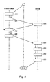
- FIG. 2 shows a schematic flow diagram of the method for authenticating the transaction data TD according to a preferred embodiment of the invention.
- the sequence of method steps shown assumes that the token 130 has already been personalized to the user.
- the transaction data TD is acquired by the client 110 by inputting the transaction data TD via an input mask 110a displayed on a display connected to the client 110 by the user.
- the thus-acquired transaction data TD is received from the client via the client interface 110b as an encrypted SSL (Secure Socket Layer) message based on conventional protocols (eg, HTTP Hypertext Transfer Protocol) through a connection through the client Network 150 (Internet) transmitted to the server 120.
- SSL Secure Socket Layer
- the transaction data TD are received or buffered at the server 120 in step 225, with the authentication module 120a waiting for the transmission of the authentication feature AM belonging to the transaction data TD from this moment.
- the token 130 generates the authentication feature AM in step 230.
- This is done by photographic recording of the input mask 110a with the transaction data TD which can be read thereon and has been previously transmitted to the server 120.
- the photographic acquisition occurs through the optical receiving module 130c and is stored in the form of an electronic image such as JPEG format in the memory of the microprocessor unit 130d.
- the stored electronic image is transmitted as authentication feature AM via the token interface 130a either directly via an alternative network 150a or indirectly via the client interface 110b and over the network 150 to the server 120.
- the authentication of the transaction data TD can take place in step 250 by the authentication feature AM being processed by the authentication module 120a by means of OCR software in order to detach the transaction data TD shown in the electronic image as a character string .
- the thus-released character string is compared by the authentication module 120a with the previously buffered transaction data TD, in particular the matches of the recipient data and the amount are checked. If they match, the transaction data TD is considered authentic, ie originating from the user, the transaction is thus authenticated.
- the transactions can then be triggered, either by the authentication module 120a or by downstream software modules, ie in particular the payment instruction can be approved.
- FIG. 3 schematically, an alternative embodiment of the invention is shown as a system for authenticating the transaction data TD.
- the system for authenticating the transaction data TD according to FIG. 3 with the exception of the token 130 is identical to the embodiment as shown in FIG. 4 is pictured.
- the token 130 according to this embodiment offers maximum local flexibility since the token 130 has only a single interface, an input interface, namely the optical receiving module 130c.
- the token interface 130a has the Token 130 via a simple held numeric display 130f communicating with the microprocessor unit 130d.
- the missing token interface 130a is compensated by the interaction with the user; in particular with the information which is controlled on the one hand on the input screen 110a by the server 120, and on the other hand by the information which is displayed on the display 130f of the token 130.
- the user enters the transaction data TD via the input mask 110a and transmits the transaction data TD to the bank server 120 or the authentication module 120a via the client interface 110b in the manner described above-for example via a secure Internet connection.
- the authentication module 120a uses a random number generator to generate a selection of digits that advantageously comprise the recipient data (account number, bank code) within the transaction data TD. This selection again communicates the authentication module 120a to the client 110, for example in the form of a signal that causes the selected digits on the output form 110a to appear colored or otherwise highlighted, for example.
- the authentication module 120a transmits a server-key-encrypted version of the selection of digits represented on the input screen, for example, in a separate window as a character string, which server key is stored in the memory of the microprocessor unit 130d of the token 130.
- this encrypted form of selecting the transaction data TD in the new window is displayed in a machine-readable form.
- the image of the window with the encrypted form of selection of the transaction data TD detected by the optical acquisition module 130c is converted into a character string and then encrypted with the server key stored in the memory and stored on the numeric display 130f of the Tokens 130 displayed.
- the user compares the clear-text selection of the transaction data TD as displayed on the display 130f of the token 130, with the representation of the selection of the transaction data TD on the input mask 110a as a color-coded selection of the transaction data TD.
- the user actuates a trigger 310 which causes the decrypted selection of the transaction data TD to be re-encrypted, but this time with a token key also stored in the memory of the microprocessor unit 130d of the token 130.
- the result of this further encryption is again a character string which is displayed in the display 130f of the token 130 to the user.
- This string represents the authentication feature AM, which the user can now enter on a corresponding field of the input mask 110a and which is now transmitted again by the client 110 via the client interface 110b to the server 120 or the authentication module 120a.
- the authentication module 120a knows the token key and can therefore compare by decrypting the received with the token key encrypted selection of the transaction data TD, whether a repeated decryption of the authentication feature AM the same number sequence is generated, as those that the authentication module 120a originally selected from the transaction data TD. If match is found, the transaction data TD is considered authenticated.
- the authentication feature AM for the transaction data TD is in accordance with the embodiment of the invention FIG. 3 an OTP which replaces the conventional TAN as a digit string (namely, the one generated by encrypting with the token key of random selection of the transaction data TD). Due to the very simple execution of the token 130, this system offers the user maximum mobility, so that clients 110 can be used that do not have any interfaces for external devices (in particular, no USB ports).
- the eavesdropper can only use the intercepted and manipulated transaction data TD or the intercepted authentication feature AM with the server 120 as part of a new transaction session.
- the server 120 is then but under the in FIG. 3 represented authentication protocol via the random generator with almost certain probability to another selection of the manipulated transaction data TD meet, making the intercepted authentication feature AM has become obsolete.
- FIG. 2 is a flowchart once again schematically illustrating the individual steps of the authentication method according to an alternative embodiment of the invention, which is described by the system in FIG. 3 was implemented.
- step 410 the transaction data TD entered via the input mask 110a on the client 110 is transmitted to the server 120 or to the authentication module 120a.
- a random generator communicating with the authentication module 120a selects in step 415 as authentication feature AM a selection from the received transaction data TD and transmits a corresponding signal to the client 110, optically distinguishing the selected transaction data TD on the input mask 110a from the unselected one Transaction data TD appears.
- the authentication module 120a encrypts the selected transaction data * TD with a server key in step 420 and transmits this encrypted form of selection of the transaction data TD back to the client 110.
- step 425 the encrypted form of the selected transaction data TD is displayed in a separate window displayed in machine-readable form on the monitor connected to the client 110.
- this encrypted selection of the transaction data TD represented on the additional window is detected by the optical reception module 130c and stored in the memory of the microprocessor unit 130d on the token 130.
- step 435 the encrypted selection of the transaction data TD is decrypted via the server key also stored in the memory, to then be displayed in plain text in step 440 in the numerical display 130f.
- the user If the display on the display 130f matches the color-coded selection of the transaction data TD on the input screen 110a, the user generates the authentication feature AM via the trigger 310 in step 450, whereby the displayed digits are re-encrypted on the display 130f, but this time with a token key also located in the memory of the microprocessor unit 130d.
- the authentication feature AM thus obtained, ie a number sequence, is then transmitted back to the authentication module 120a of the server 120 via the client or the client interface 110b after being input by the user into an OTP field of the input mask 110a in step 470.
- the authentication feature AM received there is then, after being decrypted by the token key known to the authentication module 120a, compared in step 480 with the selection of the transaction data TD previously made by the authentication module 120a. If these two digit sequences match, the signal for successful authentication is given in step 490.
Applications Claiming Priority (1)
| Application Number | Priority Date | Filing Date | Title |
|---|---|---|---|
| DE102008037793A DE102008037793A1 (de) | 2008-08-14 | 2008-08-14 | Phototoken |
Publications (2)
| Publication Number | Publication Date |
|---|---|
| EP2154656A2 true EP2154656A2 (fr) | 2010-02-17 |
| EP2154656A3 EP2154656A3 (fr) | 2010-06-09 |
Family
ID=41403116
Family Applications (1)
| Application Number | Title | Priority Date | Filing Date |
|---|---|---|---|
| EP09010335A Ceased EP2154656A3 (fr) | 2008-08-14 | 2009-08-11 | Photogène |
Country Status (2)
| Country | Link |
|---|---|
| EP (1) | EP2154656A3 (fr) |
| DE (1) | DE102008037793A1 (fr) |
Families Citing this family (2)
| Publication number | Priority date | Publication date | Assignee | Title |
|---|---|---|---|---|
| DE102010050195A1 (de) * | 2010-10-31 | 2012-05-03 | Tu Darmstadt | Lesegerät als elektronischer Ausweis |
| DE102010052666B4 (de) | 2010-11-26 | 2019-01-03 | Trustonic Ltd. | Verfahren zur sicheren mobilen Transaktionsdurchführung |
Citations (6)
| Publication number | Priority date | Publication date | Assignee | Title |
|---|---|---|---|---|
| DE10015098A1 (de) | 2000-03-28 | 2001-10-25 | Giesecke & Devrient Gmbh | Verfahren und Endgerät zur Durchführung von Transaktionen unter Einschaltung eines tragbaren Datenträgers |
| DE10045924A1 (de) | 2000-09-14 | 2002-04-04 | Giesecke & Devrient Gmbh | Verfahren zum Absichern einer Transaktion auf einem Computernetzwerk |
| EP1211841A1 (fr) | 2000-06-23 | 2002-06-05 | Esignus, S.L. | Dispositif de signature externe pour ordinateur personnel a entree optique de donnees via le moniteur |
| DE10152462A1 (de) | 2001-10-24 | 2003-06-18 | Giesecke & Devrient Gmbh | Signatur eines Dokuments |
| DE102004046847A1 (de) | 2004-09-27 | 2006-04-13 | Giesecke & Devrient Gmbh | System, Verfahren und tragbarer Datenträger zur Erzeugung einer digitalen Signatur |
| EP1802155A1 (fr) * | 2005-12-21 | 2007-06-27 | Cronto Limited | Système et procédé pour authentification dynamique basée sur plusieurs facteurs |
Family Cites Families (14)
| Publication number | Priority date | Publication date | Assignee | Title |
|---|---|---|---|---|
| EP0566811A1 (fr) * | 1992-04-23 | 1993-10-27 | International Business Machines Corporation | Méthode et système d'authentification à l'aide d'une carte à puce |
| US7171016B1 (en) * | 1993-11-18 | 2007-01-30 | Digimarc Corporation | Method for monitoring internet dissemination of image, video and/or audio files |
| DE19838605A1 (de) * | 1998-08-25 | 2000-03-02 | Siemens Ag | Verfahren und Vorrichtung zur Bildung einer Nachweisgröße, die einen Nachweis eines digitalen Signierens einer elektronischen Datei ermöglicht sowie Verfahren und Vorrichtung zum Nachweis, daß eine elektronische Datei digital signiert worden ist |
| FI108373B (fi) * | 1998-12-16 | 2002-01-15 | Sonera Smarttrust Oy | Menetelmõ ja jõrjestelmõ digitaalisen allekirjoituksen toteuttamiseksi |
| EP1035461A3 (fr) * | 1999-03-11 | 2004-04-14 | BDC - EDV Consulting GmbH | Terminal pour confirmation sécurisée de données et méthode correspondante |
| EP1055989A1 (fr) * | 1999-05-28 | 2000-11-29 | Hewlett-Packard Company | Système pour marquer un document avec une signature numérique |
| US20080172343A1 (en) * | 2000-06-20 | 2008-07-17 | Hubert Juillet | Data processing method for secure Internet transactions |
| DE10158880A1 (de) * | 2001-11-30 | 2003-07-03 | Deutsche Telekom Ag | Verfahren und Vorrichtung zur Erhöhung der Sicherheit beim elektronischen Signieren von Dokumenten |
| US20050102233A1 (en) * | 2003-11-06 | 2005-05-12 | Sharp Laboratories Of America, Inc. | Associating mobile phone to vending machine via bar-code encoded data, CCD camera and internet connection |
| DE102005008258A1 (de) * | 2004-04-07 | 2005-10-27 | Giesecke & Devrient Gmbh | Datenträger mit TAN-Generator und Display |
| KR100678169B1 (ko) * | 2004-10-28 | 2007-02-02 | 삼성전자주식회사 | 서로 이격된 두 단말기 사이의 데이터 전송 시스템 및 방법 |
| EP1713230B1 (fr) * | 2005-04-11 | 2011-07-20 | AXSionics AG | Système et méthode pour sécurité de l'utilisator lors de l'établissement d'une communication sur un reseau non securise |
| JP4755689B2 (ja) * | 2005-07-27 | 2011-08-24 | インターナショナル・ビジネス・マシーンズ・コーポレーション | 正規受信者への安全なファイル配信のためのシステムおよび方法 |
| DE102005048205B4 (de) * | 2005-10-07 | 2012-12-27 | Vodafone Holding Gmbh | Verfahren und System zur elektronischen Recherche zu Inhalten innerhalb einer Präsentation |
-
2008
- 2008-08-14 DE DE102008037793A patent/DE102008037793A1/de not_active Ceased
-
2009
- 2009-08-11 EP EP09010335A patent/EP2154656A3/fr not_active Ceased
Patent Citations (6)
| Publication number | Priority date | Publication date | Assignee | Title |
|---|---|---|---|---|
| DE10015098A1 (de) | 2000-03-28 | 2001-10-25 | Giesecke & Devrient Gmbh | Verfahren und Endgerät zur Durchführung von Transaktionen unter Einschaltung eines tragbaren Datenträgers |
| EP1211841A1 (fr) | 2000-06-23 | 2002-06-05 | Esignus, S.L. | Dispositif de signature externe pour ordinateur personnel a entree optique de donnees via le moniteur |
| DE10045924A1 (de) | 2000-09-14 | 2002-04-04 | Giesecke & Devrient Gmbh | Verfahren zum Absichern einer Transaktion auf einem Computernetzwerk |
| DE10152462A1 (de) | 2001-10-24 | 2003-06-18 | Giesecke & Devrient Gmbh | Signatur eines Dokuments |
| DE102004046847A1 (de) | 2004-09-27 | 2006-04-13 | Giesecke & Devrient Gmbh | System, Verfahren und tragbarer Datenträger zur Erzeugung einer digitalen Signatur |
| EP1802155A1 (fr) * | 2005-12-21 | 2007-06-27 | Cronto Limited | Système et procédé pour authentification dynamique basée sur plusieurs facteurs |
Also Published As
| Publication number | Publication date |
|---|---|
| DE102008037793A1 (de) | 2010-02-18 |
| EP2154656A3 (fr) | 2010-06-09 |
Similar Documents
| Publication | Publication Date | Title |
|---|---|---|
| EP2949094B1 (fr) | Procédé d'authentification d'un usager vis-à-vis d'un distributeur automatique | |
| EP3078218B1 (fr) | Contrôle d'accès et d'utilisation pour un véhicule automobile | |
| DE10224209A1 (de) | Autorisierungseinrichtung-Sicherheitsmodul -Terminal-System | |
| DE102011082101A1 (de) | Verfahren zur Erzeugung eines Soft-Tokens, Computerprogrammprodukt und Dienst-Computersystem | |
| EP3289508A1 (fr) | Procédé pour produire une signature électronique | |
| EP2528045A1 (fr) | Procédé et ordinateur de service ainsi que système d'authentification sans carte | |
| DE102011116489A1 (de) | Mobiles Endgerät, Transaktionsterminal und Verfahren zur Durchführung einer Transaktion an einem Transaktionsterminal mittels eines mobilen Endgeräts | |
| DE102017122799A1 (de) | Verfahren und Anordnung zur Übermittlung von Transaktionsdaten unter Nutzung eines öffentlichen Datennetzes | |
| DE102011055297B4 (de) | Verfahren sowie Netzwerk-System und Authentifizierungsvorrichtung zur Authentifizierung in einer Netzwerkapplikation | |
| EP2512090B1 (fr) | Procédé destiné à l'authentification d'un participant | |
| EP2881289B1 (fr) | Procédé de déverrouillage d'une installation de verrouillage de véhicule | |
| EP3206151B1 (fr) | Procédé et système d'authentification d'un appareil de télécommunication mobile sur un système informatique de service et appareil de télécommunication mobile | |
| CZ2015472A3 (cs) | Způsob navazování chráněné elektronické komunikace, bezpečného přenášení a zpracování informací mezi třemi a více subjekty | |
| WO2013011043A1 (fr) | Système mobile pour transactions financières | |
| EP3014539A1 (fr) | Procédé de transaction électronique et système informatique | |
| EP2154656A2 (fr) | Photogène | |
| EP2996299B1 (fr) | Procédé et système d'autorisation d'une action sur un système auto-commandé | |
| EP2879073B1 (fr) | Procédé de transaction électronique et système informatique | |
| WO2017036455A2 (fr) | Dispositif et procédé d'authentification et d'autorisation de personnes | |
| DE102005014194A1 (de) | Lesegerät mit integrierter Kryptographieeinheit | |
| EP3361436B1 (fr) | Procédé d'autorisation d'une transaction | |
| EP2920754B1 (fr) | Procédé de réalisation de transactions | |
| DE102019109343A1 (de) | Verfahren und Vorrichtung zur Übertragung digitaler Daten | |
| DE102013022448B3 (de) | Elektronisches Transaktionsverfahren und Computersystem | |
| EP2819079B1 (fr) | Procédé de transaction électronique et système informatique |
Legal Events
| Date | Code | Title | Description |
|---|---|---|---|
| PUAI | Public reference made under article 153(3) epc to a published international application that has entered the european phase |
Free format text: ORIGINAL CODE: 0009012 |
|
| AK | Designated contracting states |
Kind code of ref document: A2 Designated state(s): AT BE BG CH CY CZ DE DK EE ES FI FR GB GR HR HU IE IS IT LI LT LU LV MC MK MT NL NO PL PT RO SE SI SK SM TR |
|
| AX | Request for extension of the european patent |
Extension state: AL BA RS |
|
| PUAL | Search report despatched |
Free format text: ORIGINAL CODE: 0009013 |
|
| AK | Designated contracting states |
Kind code of ref document: A3 Designated state(s): AT BE BG CH CY CZ DE DK EE ES FI FR GB GR HR HU IE IS IT LI LT LU LV MC MK MT NL NO PL PT RO SE SI SK SM TR |
|
| AX | Request for extension of the european patent |
Extension state: AL BA RS |
|
| RIC1 | Information provided on ipc code assigned before grant |
Ipc: G07F 7/10 20060101ALI20100506BHEP Ipc: H04L 29/06 20060101AFI20100506BHEP |
|
| 17P | Request for examination filed |
Effective date: 20101209 |
|
| 17Q | First examination report despatched |
Effective date: 20160810 |
|
| STAA | Information on the status of an ep patent application or granted ep patent |
Free format text: STATUS: THE APPLICATION HAS BEEN REFUSED |
|
| 18R | Application refused |
Effective date: 20170429 |