EP2154629A1 - Optical recognition code recognized result displaying method - Google Patents
Optical recognition code recognized result displaying method Download PDFInfo
- Publication number
- EP2154629A1 EP2154629A1 EP08752409A EP08752409A EP2154629A1 EP 2154629 A1 EP2154629 A1 EP 2154629A1 EP 08752409 A EP08752409 A EP 08752409A EP 08752409 A EP08752409 A EP 08752409A EP 2154629 A1 EP2154629 A1 EP 2154629A1
- Authority
- EP
- European Patent Office
- Prior art keywords
- data
- code symbol
- code
- recognized
- creating
- Prior art date
- Legal status (The legal status is an assumption and is not a legal conclusion. Google has not performed a legal analysis and makes no representation as to the accuracy of the status listed.)
- Withdrawn
Links
Images


Classifications
-
- G—PHYSICS
- G06—COMPUTING OR CALCULATING; COUNTING
- G06K—GRAPHICAL DATA READING; PRESENTATION OF DATA; RECORD CARRIERS; HANDLING RECORD CARRIERS
- G06K7/00—Methods or arrangements for sensing record carriers, e.g. for reading patterns
- G06K7/10—Methods or arrangements for sensing record carriers, e.g. for reading patterns by electromagnetic radiation, e.g. optical sensing; by corpuscular radiation
- G06K7/14—Methods or arrangements for sensing record carriers, e.g. for reading patterns by electromagnetic radiation, e.g. optical sensing; by corpuscular radiation using light without selection of wavelength, e.g. sensing reflected white light
-
- G—PHYSICS
- G06—COMPUTING OR CALCULATING; COUNTING
- G06K—GRAPHICAL DATA READING; PRESENTATION OF DATA; RECORD CARRIERS; HANDLING RECORD CARRIERS
- G06K19/00—Record carriers for use with machines and with at least a part designed to carry digital markings
- G06K19/06—Record carriers for use with machines and with at least a part designed to carry digital markings characterised by the kind of the digital marking, e.g. shape, nature, code
- G06K19/06009—Record carriers for use with machines and with at least a part designed to carry digital markings characterised by the kind of the digital marking, e.g. shape, nature, code with optically detectable marking
- G06K19/06018—Record carriers for use with machines and with at least a part designed to carry digital markings characterised by the kind of the digital marking, e.g. shape, nature, code with optically detectable marking one-dimensional coding
Definitions
- the present invention relates to a technology of optically reading in a plurality of optical recognition codes (also called automatic recognition code tags), collectively recognizing the read-in codes, finding out a target code symbol(s) (also called a tag), and displaying the result to the operator in an easy-to-understand manner. That is, the present invention relates to a technology of optically reading out and decoding optical recognition codes.
- optical recognition codes also called automatic recognition code tags
- target code symbol(s) also called a tag
- barcodes are among the well-known optical recognition codes.
- an image of a certain region including a 1D color bit code (s) is taken into photographing means such as a CCD camera or the like.
- 1D color bit codes are recognized by reading in and processing the image of a certain region.
- Patent Document 1 discloses a cutout method able to easily cut barcodes out of characters and/or images.
- Patent Document 2 discloses a method of printing barcodes comprising a great amount of information in a small space, characterized, in particular, by utilizing barcodes cut out as a set of minor arcs with a central angle ⁇ .
- Patent Document 3 discloses an apparatus for reading out two-dimensional barcodes; and in particular discloses a technology characterized by switching decoding means in accordance with the image qualities.
- Patent Document 4 discloses a barcode cutout method able to read out a plurality of barcodes. According to the technology disclosed herein, it is possible to continuously recognize even those with irregular left and/or right margins, thereby being able to cut out a plurality of barcodes.
- 1D color bit codes are suitable for recognizing at a time a plurality of 1D color bit codes included in a single image.
- an object of the present invention is to provide a method for displaying the results in an improved manner in the case of collectively reading in and recognizing a plurality of 1D color bit codes.
- Another object of the present invention is to accomplish a technology able to search for a color bit code of a desired value.
- Yet another object of the present invention is to provide a method for displaying the results in an improved manner in the case of utilizing RFID tags in combination with the 1D color bit codes.
- the present invention provides an optical recognition code recognizer capturing an image including a code symbol that is a symbol of an optical recognition code and decoding a data denoted by the code symbol from an obtained original image, the recognizer comprising: a corresponding pattern specific display creating means for creating a "corresponding pattern specific display” indicating the code symbol; and a displaying means for displaying the created corresponding pattern specific display superimposed on the original image.
- the present invention provides an optical recognition code recognizer capturing an image including a code symbol that is a symbol of an optical recognition code and decoding a data denoted by the code symbol from an obtained original image, the recognizer comprising: a recognizing means for decoding a data denoted by the code symbol; a recognized data display creating means for creating an image denoting the data in association with the code symbol from which the data is recognized; and a displaying means for displaying the created recognized data display superimposed on the original image.
- association means "to know the data as of the code symbol", and typically refers to displaying the data more adjacent to the code symbol than other data displays. However, the display does not have to be adjacent to the code symbol as long as the data can be known of which code symbol, such as utilizing a lead line and the like.
- association will be used in this sense.
- optical recognition code recognizer according to the description of (1), further comprising: a recognizing means for decoding a data denoted by the code symbol; a recognized data display creating means for creating an image denoting the data in association with the corresponding pattern specific display of the code symbol from which the data is recognized; and a displaying means for displaying the created recognized data display superimposed on the original image.
- the present invention provides an optical recognition code recognizer capturing an image including a plurality of code symbols each of which is a symbol of an optical recognition code and decoding each data denoted by each code symbol from an obtained original image, the recognizer comprising: a corresponding pattern specific display creating means for creating a "corresponding pattern specific display” indicating the code symbol; and a displaying means for displaying the created corresponding pattern specific display superimposed on the original image.
- the present invention provides an optical recognition code recognizer capturing an image including a plurality of code symbols each of which is a symbol of an optical recognition code and decoding each data denoted by each code symbol from an obtained original image, the recognizer comprising: a recognizing means for decoding a data denoted by the code symbol; a recognized data display creating means for creating an image denoting the data in association with the code symbol from which the data is recognized; and a displaying means for displaying the created recognized data display superimposed on the original image.
- optical recognition code recognizer according to the description of (4), further comprising: a recognizing means for decoding a data denoted by the code symbol; a recognized data display creating means for creating an image denoting the data in association with the corresponding pattern specific display of the code symbol from which the data is recognized; and a displaying means for displaying the created recognized data display superimposed on the original image.
- the optical recognition code recognizer according to any one of the descriptions of (1) to (6), further comprising: a nonconforming pattern display creating means for creating a nonconforming pattern display indicating an un-decodable region of a plurality of serial color areas in the original image; and a displaying means for displaying the nonconforming pattern display superimposed on the original image.
- the optical recognition code recognizer according to the description of (7), wherein the nonconforming pattern image nonconforms to any of a preset cell alignment rule, cell number rule and cell alignment numerical rule, and conforms to any or all of a preset cell alignment quasi rule, cell number quasi rule and cell alignment numerical quasi rule.
- the present invention provides an optical recognition code recognizer capturing an image including a code symbol that is a symbol of an optical recognition code, decoding a data denoted by the code symbol from an obtained original image, and checking whether a decoded result conforms to a search object data
- the recognizer comprising: a recognizing means for decoding a data denoted by the code symbol; a checking means for checking whether the decoded result conforms to the search object data; a corresponding pattern specific display creating means for creating a "target corresponding pattern specific display” indicating the code symbol when the check result shows that the decoded result conforms to the search object data; and a displaying means for displaying the created corresponding pattern specific display superimposed on the original image.
- the optical recognition code recognizer according to the description of (9), wherein the corresponding pattern specific display creating means creates a nontarget corresponding pattern specific display indicating the code symbol when the check result shows that the decoded result nonconforms to the search object data; the nontarget corresponding pattern specific display being different from the target corresponding pattern specific display.
- the optical recognition code recognizer according to any one of the descriptions of (1) to (6), further comprising: an RFID reading means for reading out an RFID tag value; and a comparing means for comparing the data decoded from the code symbol with the data read out by the RFID reading means, wherein the corresponding pattern specific display creating means creates different corresponding pattern specific displays between the cases that the data decoded from the code symbol conforms and nonconforms to the data read out by the RFID reading means.
- RFID tag is a tag communicating through radio waves
- any kind of the tags may be applied, such as tags at times also referred to as wireless tags, IC tags and the like.
- RFID tag is used in this sense.
- the optical recognition code recognizer according to any one of the descriptions of (1) to (6), further comprising: an RFID reading means for reading out an RFID tag value; and a comparing means for comparing the data decoded from the code symbol with the data read out by the RFID reading means, wherein the recognized data display creating means creates different recognized data displays between the cases that the data decoded from the code symbol conforms and nonconforms to the data read out by the RFID reading means.
- the present invention provides an optical recognition code recognizing method capturing an image including a code symbol that is a symbol of an optical recognition code and decoding a data denoted by the code symbol from an obtained original image, the method comprising the steps of: (a13) creating a "corresponding pattern specific display” indicating the code symbol; and (b13) displaying the created corresponding pattern specific display superimposed on the original image.
- the present invention provides an optical recognition code recognizing method capturing an image including a code symbol that is a symbol of an optical recognition code and decoding a data denoted by the code symbol from an obtained original image, the method comprising the steps of: (a14) decoding a data denoted by the code symbol; (b14) creating a recognized data display by creating an image denoting the data in association with the code symbol from which the data is recognized; and (c14) displaying the created recognized data display superimposed on the original image.
- optical recognition code recognizing method further comprising the steps of: (a15) decoding a data denoted by the code symbol; (b15) creating a recognized data display by creating an image denoting the data in association with the corresponding pattern specific display of the code symbol from which the data is recognized; and (c15) displaying the created recognized data display superimposed on the original image.
- the present invention provides an optical recognition code recognizing method capturing an image including a plurality of code symbols each of which is a symbol of an optical recognition code and decoding each data denoted by each code symbol from an obtained original image, the method comprising the steps of: (a16) creating a "corresponding pattern specific display” indicating the code symbol; and (b16) displaying the created corresponding pattern specific display superimposed on the original image.
- the present invention provides an optical recognition code recognizing method capturing an image including a plurality of code symbols each of which is a symbol of an optical recognition code and decoding each data denoted by each code symbol from an obtained original image, the method comprising the steps of: (a17) decoding a data denoted by the code symbol; (b17) creating a recognized data display by creating an image denoting the data in association with the code symbol from which the data is recognized; and (c17) displaying the created recognized data display superimposed on the original image.
- optical recognition code recognizing method further comprising the steps of: (a18) decoding a data denoted by the code symbol; (b18) creating a recognized data display by creating an image denoting the data in association with the corresponding pattern specific display of the code symbol from which the data is recognized; and (c18) displaying the created recognized data display superimposed on the original image.
- optical recognition code recognizing method according to any one of the descriptions of (13) to (18), further comprising the steps of: (a19) creating a nonconforming pattern display indicating an un-decodable region of a plurality of serial color areas in the original image; and (b19) displaying the nonconforming pattern display superimposed on the original image.
- the optical recognition code recognizing method according to the description of (19), wherein the nonconforming pattern image nonconforms to any of a preset cell alignment rule, cell number rule and cell alignment numerical rule, and conforms to any or all of a preset cell alignment quasi rule, cell number quasi rule and cell alignment numerical quasi rule.
- the present invention provides an optical recognition code recognizing method capturing an image including a code symbol that is a symbol of an optical recognition code, decoding a data denoted by the code symbol from an obtained original image, and checking whether a decoded result conforms to a search object data, the method comprising the steps of: (a21) decoding a data denoted by the code symbol; (b21) checking whether the decoded result conforms to the search object data; (c21) creating a "target corresponding pattern specific display" indicating the code symbol when the check result shows that the decoded result conforms to the search object data; and (d21) displaying the created target corresponding pattern specific display superimposed on the original image.
- step (c21) creates a nontarget corresponding pattern specific display indicating the code symbol when the check result shows that the decoded result nonconforms to the search object data; the nontarget corresponding pattern specific display being different from the target corresponding pattern specific display.
- optical recognition code recognizing method according to any one of the descriptions of (13) to (18), further comprising the steps of: (a23) reading out an RFID tag value; and (b23) comparing the data decoded from the code symbol with the data read out in step (a23), wherein different corresponding pattern specific displays are created in the step of creating the corresponding pattern specific display between the cases that the data decoded from the code symbol conforms and nonconforms to the data read out in step (a23).
- optical recognition code recognizing method according to any one of the descriptions of (13) to (18), further comprising the steps of: (a24) reading out an RFID tag value; and (b24) comparing the data decoded from the code symbol with the data read out in step (a24), wherein different recognized data displays are created in the step of creating the recognized data display between the cases that the data decoded from the code symbol conforms and nonconforms to the data read out in step (a24).
- the present invention provides a program activating a computer as an optical recognition code recognizer capturing an image including a code symbol that is a symbol of an optical recognition code and decoding a data denoted by the code symbol from an obtained original image, the program setting the computer to execute the procedures of: (a25) creating a "corresponding pattern specific display” indicating the code symbol; and (b25) displaying the created corresponding pattern specific display superimposed on the original image.
- the present invention provides a program activating a computer as an optical recognition code recognizer capturing an image including a code symbol that is a symbol of an optical recognition code and decoding a data denoted by the code symbol from an obtained original image, the program setting the computer to execute the procedures of: (a26) decoding a data denoted by the code symbol; (b26) creating a recognized data display by creating an image denoting the data in association with the code symbol from which the data is recognized; and (c26) displaying the created recognized data display superimposed on the original image.
- the present invention provides a program activating a computer as an optical recognition code recognizer capturing an image including a plurality of code symbols each of which is a symbol of an optical recognition code and decoding each data denoted by each code symbol from an obtained original image, the program setting the computer to execute the procedures of: (a28) creating a "corresponding pattern specific display” indicating the code symbol; and (b28) displaying the created corresponding pattern specific display superimposed on the original image.
- the present invention provides a program activating a computer as an optical recognition code recognizer capturing an image including a plurality of code symbols each of which is a symbol of an optical recognition code and decoding each data denoted by each code symbol from an obtained original image, the program setting the computer to execute the procedures of: (a29) decoding a data denoted by the code symbol; (b29) creating a recognized data display by creating an image denoting the data in association with the code symbol from which the data is recognized; and (c29) displaying the created recognized data display superimposed on the original image.
- the program according to any one of the descriptions of (25) to (30), further setting the computer to execute the procedures of: (a31) creating a nonconforming pattern display indicating an un-decodable region of a plurality of serial color areas in the original image; and (b31) displaying the nonconforming pattern display superimposed on the original image.
- the present invention provides a program activating a computer as an optical recognition code recognizer capturing an image including a code symbol that is a symbol of an optical recognition code, decoding a data denoted by the code symbol from an obtained original image, and checking whether a decoded result conforms to a search object data, the program setting the computer to execute the procedures of: (a33) decoding a data denoted by the code symbol; (b33) checking whether the decoded result conforms to the search object data; (c33) creating a "target corresponding pattern specific display" indicating the code symbol when the check result shows that the decoded result conforms to the search object data; and (d33) displaying the created target corresponding pattern specific display superimposed on the original image.
- procedure (c33) creates a nontarget corresponding pattern specific display indicating the code symbol when the check result shows that the decoded result nonconforms to the search object data; the nontarget corresponding pattern specific display being different from the target corresponding pattern specific display.
- the program according to any one of the descriptions of (25) to (30), further setting the computer to execute the procedures of: (a35) reading out an RFID tag value; and (b35) comparing the data decoded from the code symbol with the data read out in procedure (a35), wherein the procedure of creating the corresponding pattern specific display creates different corresponding pattern specific displays between the cases that the data decoded from the code symbol conforms and nonconforms to the data read out in procedure (a35).
- the program according to any one of the descriptions of (25) to (30), further setting the computer to execute the procedures of: (a36) reading out an RFID tag value; and (b36) comparing the data decoded from the code symbol with the data read out in procedure (a36), wherein the procedure of creating the recognized data display creates different recognized data displays between the cases that the data decoded from the code symbol conforms and nonconforms to the data read out in procedure (a36) .
- the display indicating the successfully read-out code symbol is superimposed on the original image, thereby being able to easily know which code symbol has been read out.
- a decoded value of the successfully read-out code symbol is displayed in such a manner as superimposed on the original image, thereby being able to easily know the data denoted by the code symbol.
- an optical recognition code of a desired value can be efficiently searched for.
- Part two An outline of a process for recognizing 1D color bit codes
- 1D color bit codes are recognized in such a manner as first digitizing an image by means of optical input means such as CCD cameras and then processing the image data. Further, a single 1D color bit code is called a "code symbol”; at times also referred to as a “tag” from its functional aspect. In this document, the term “code symbol” is used. Further, a single code symbol is formed by a predetermined number of series color areas (called “cells” as described above).
- a plurality of code symbols are read out in the same manner as a single code symbol is, by photographing an image including the plurality of code symbols, which are thereby contained in a digital image, from which each data of each code symbol can be recognized.
- a characteristic of the embodiment is to display the code symbol data that are the result of collectively recognizing a plurality of code symbols (also called recognized data) and the data indicating successfully recognized code symbols (corresponding pattern specific display) superimposed on the code symbol image.
- the following data are utilized to display in such a manner as superimposed on the code symbol image.
- Corresponding pattern specific display a graphic pattern for showing a finally recognized code symbol; for example, a rectangular frame (e.g., using a conspicuous color such as orange color and the like) may be utilized.
- the corresponding pattern specific display (rectangular frame) is performed by a corresponding pattern specific displaying means. Further, a data displaying means actually displays the data read-out from the code symbol in the vicinity of the corresponding pattern specific display.
- Fig. 1 shows a conceptual configuration diagram of an optical recognition code recognizer utilizing the method for displaying a recognition result in accordance with the embodiment.
- an optical recognition code recognizer 10 is provided with a camera means 12, which photographs a scene 20 including optical recognition codes. Further, the optical recognition code recognizer 10 is provided with a computer 14 for processing the photographed image, and a displaying means 16 for displaying the read-out code symbol image and recognition result, connected to the computer 14. Other members (not shown), such as a keyboard for the operator to input operating instructions and the like are also provided.
- the computer 14 realizes each means as shown in Fig. 2 by executing a program stored in a storing means therein.
- Fig. 2 shows a functional block diagram of the computer 14.
- a recognizing means 14a recognizes an optical recognition code based on a code symbol image (original image) and outputs a recognition result, which is commonly a numerical data such as "123456"; yet other characters and symbols are also possible, of course.
- a characteristic point in the embodiment exists in that the recognizing means 14a outputs an image showing the region of the successfully recognized optical recognition code (called recognized code symbol image).
- a corresponding pattern specific display creating means 14b creates an image of such a rectangular frame as encloses the region of the successfully recognized optical recognition code in the recognized code symbol image.
- the frame is called corresponding pattern specific display.
- the operator is able to know that an optical recognition code of which position was recognized.
- a recognized data display creating means 14c creating an image displaying the recognition result "123456" in the vicinity of the region of the successfully recognized optical recognition code denoting the recognition result "123456” based on the information such as the recognition result "123456", etc., and the recognized code symbol image.
- Such "123456" in an image form is called a recognized data display.
- the recognized data display creating means 14c determines where to locate the "vicinity" based on the recognized code symbol image. For example, since the region of the recognized code symbol is knowable from the recognized code symbol image, it is preferred to take such positions as below the lower edge of the region at a predetermined distance therefrom.
- the recognized data is created in such a manner as to display in the "vicinity" of the region of the optical recognition code.
- the corresponding pattern specific display is rectangular, it is also preferable to create the recognized code in such a manner as to be displayed parallel to one side of the rectangle. In such case, the corresponding pattern specific display is supplied to the recognized data display creating means 14c. Further, such unification in direction is also a preferred example of "association" set forth in the claims.
- a compositing means 14d creates an image for finally displaying to the operator by superimposing the corresponding pattern specific display and recognized data display on the code symbol image.
- a displaying means 16 displays the finally created image to the operator.
- the "corresponding pattern specific display” utilizes a rectangle enclosing the code symbol, e.g., an orange rectangular frame.
- any kind of display is applicable as long as the code symbol can be indicated, such as green, red and the like.
- such a display is also preferable as changes the color of the vicinity of the relevant code symbol.
- marks such as arrow marks and the like indicating the relevant code symbol.
- an image denoting the data (e.g., 123456 in an image form) is displayed in the vicinity of the corresponding pattern specific display.
- the "corresponding pattern specific display” indicating the code symbol conform to the image of the recognized data in color and line type, which is thereby easy to understand and easy for the operator to read out with the unaided eye.
- the corresponding pattern specific display is an orange rectangular frame
- the unaided eye will be given a sense of unity, and the operator can be clearly informed of an additional and assistant data display not available in the original code symbol image.
- the recognized data display described above is displayed for each recognized optical recognition code. Further, in the same manner, the corresponding pattern specific display is also displayed for each recognized optical recognition code.
- a target code symbol (only) is presented to the operator through such a process as the "corresponding pattern specific displaying means” performs the corresponding pattern specific display and the "data displaying means” displays the read-out data (code symbol data) of the target code symbol (conforming to the predetermined data).
- a predetermined data e.g., "1234"
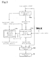
- Fig. 3 shows a functional block diagram of the computer 14 in this case.
- the functional block diagram of the computer 14 in this case is almost the same as Fig. 2 except for the following aspects.
- the recognized data display creating means 14c is provided beforehand from external with an optical recognition code value of a search object (called search code), stored in a predetermined storing means (not shown) inputted in advance by the operator through inputting means such as a keyboard and the like.
- search code an optical recognition code value of a search object
- the recognized data display creating means 14c creates a recognized data display and further outputs a message (conforming signal) indicating that the recognition result has conformed to the external only in the case that the recognition result conforms to the search code value.
- the corresponding pattern specific display creating means 14b creates a corresponding pattern specific display only in the case of being informed of the "conforming" from the recognized data display creating means 14c.
- the compositing means 14d creates an image superimposing the corresponding pattern specific display and recognized data display on the code symbol image.
- the displaying means 16 displays the created image to the operator.
- the operator can thereby know that the target optical recognition code has been recognized.
- the operator can find out the desired object from a number of code symbols, thereby being able to correctly search for products, documents and the like.
- Part 4-2 Display of the codes that are not of the search object
- the recognized data display creating means 14c does not non-create a recognized data display but creates a recognized data display different in aspect from that in the conforming case.
- a plurality of search code values for the search objects can also be designated.
- the recognized data display and the corresponding pattern display are configured such as to be performed when the recognition result conforms to any one of the search code values.
- the "recognized data display" of the recognition result e.g., "1234" and the like
- the operator can easily know which optical recognition code has been found out of the search objects.
- the code symbol candidates cut out of the code symbols in image processing are to be finally recognized after passing through a number of check steps for checking color alignment conformity, code conformity (to the color cell number and check digit) and the like.
- nonconforming pattern display The display for such nonconforming patterns is called “nonconforming pattern display” herein. As described in Part 4-2, it is preferable to perform the “nonconforming pattern display” in such a manner as changing colors, displaying dashed rectangular frames and the like. In addition, it is also preferred to display other information as will be described next instead of the "data display”.
- nonconforming step display showing the step wherein nonconformity is proved may be performed instead of the "data display”.
- the "nonconforming pattern display” (a rectangular frame different in color and the like) may be of one kind only.
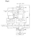
- Fig. 4 shows a functional block diagram of the computer 14 performing such behaviors.
- Fig. 4 The functional block diagram shown in Fig. 4 is almost the same as the functional block diagram of Fig. 2 except for the following aspects.
- a recognizing means 44a outputs not only a "recognition result” but also information with respect to that which could not be recognized. In such case, a "nonconforming result” indicating “did not pass the validity check for component cells” or the like is outputted. This is, actually, the information indicating the not passed check. The nonconforming result facilitates finding out which check (check step) was not passed.
- the recognizing means 44a does not output the recognized code symbol image but a "nonconforming code symbol image" when the "nonconforming result” is outputted.
- the "nonconforming code symbol image” is similar to the “recognized code symbol image", indicating a certain region; yet the image outputted at the same time as the "nonconforming result", is the “nonconforming code symbol image”.
- the image outputted at the same time as the "recognition result" is the "recognized code symbol image", as shown in the examples described so far.
- a corresponding pattern specific display creating means 44b and a recognized data display creating means 44c perform either of the following modes.
- the corresponding pattern specific display creating means 44b creates not only a “corresponding pattern specific display” (orange) but also a “nonconforming pattern display” (green). These "corresponding pattern specific display” and “nonconforming pattern display” are of the same frame graphics, but different in color affixed thereto (orange and green), thereby being configured to be easily recognizable with the unaided eye.
- Mode 1 several kinds (green, blue and yellow) of the nonconforming pattern displays are provided to indicate which check (check step) was not passed with a different color for each check (step). By virtue of these colors, cases of nonconforming to the component cell number, end-point condition, internal check code and the like can be indicated respectively.
- the recognized data display creating means 44c creates a recognized data display based on the recognition result and recognized code symbol image. However, nothing will be outputted when a nonconforming result is outputted.
- the corresponding pattern specific display creating means 44b creates not only a “corresponding pattern specific display” (orange) but also a “nonconforming pattern display” (green).
- These "corresponding pattern specific display” (orange) and “nonconforming pattern display” (green) are of the same frame graphics, but different in color affixed thereto (orange and green), thereby being configured to be easily recognizable with the unaided eye.
- the "nonconforming pattern display” (green) does not show any information about which check step was not passed.
- the recognized data display creating means 44c creates a nonconforming step display from the "nonconforming result" and "nonconforming code symbol image". This corresponds to the recognized data display when the data is correctly recognized, so as to display the step not passed in the vicinity of the nonconforming pattern display.
- “The third check step was not passed” and the like are preferable; yet displays such as “ERROR 3", or more specifically, "Cell number nonconforming", etc., are also preferred.
- Modes 1 and 2 are different only in the "place" of indicating the check step not passed, but the same in the contents to display.
- a compositing means 44d composites the displays created in the above manner with the code symbol image for the display means 16 to display.
- an original image (code symbol image) is inputted.
- the image is photographed by the camera means 12, and taken into the computer 14.
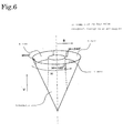
- the recognizing means 44a assigns four values to the code symbol image.
- the four values are assigned according to the color phrase of an image data, as shown in Fig. 6 , which is a circular cone denoting an HSV color notation.
- the vertical direction represents color value (brightness)
- the circumferential position represents color phrase (hue)
- the distance from the center represents the color purity (saturation).
- Other regions, that is, regions with the saturation below a predetermined value are all considered as achromatic colors and converted uniformly into white (W).
- each pixel in the code symbol image is converted into four colors as R, G, B, and W (four value assignment).
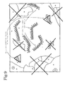
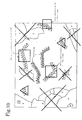
- Fig. 7 shows a conversion example wherein the scene 20 is photographed and four values are assigned thereto.
- R represents red, B blue, G green, and W white.
- R, G and B are called "code component colors for they are colors forming the optical recognition code, while W is called a background color.
- the recognizing means 44a cuts out the portions of assembled code component colors.
- Each "assembly” becomes a “candidate” of an optical recognition code.
- a number of such "assemblies” exist in a code symbol image.
- an assembly region is called a code candidate region.
- step S5-4 the 1D color bit code recognition is started for each code candidate region.
- the process as will be described below is carried out by the recognizing means 44a.
- the step S5-5 determines whether all code candidate regions have been determined. If all done, the process moves on to the step S5-6; if not, it moves on to the step S5-7 to continue the recognition.
- step S5-6 an image for displaying the final result is displayed by the displaying means 16.
- the step S5-7 checks whether the area number of a code candidate region conforms to the cell number of a 1D color bit code.
- the cell number is a predetermined number (10 cells, 20 cells and the like), a predetermined range of numbers (13 to 15 cells) is also applicable (flexible length) other than a single number (fixed length).
- FIG. 9 A check result of the area number (cell number) is shown in Fig. 9 .
- those newly dropping out of the candidates are marked with " ⁇ ".
- the code candidate regions are five.
- the check result shows that the area number of the code candidate region nonconforms to the cell number of the 1D color bit code, it is considered as a noise and thus excluded from the code candidate regions, and the process moves on to the step S5-8.
- the area number of the code candidate region conforms to the cell number of the 1D color bit code, it is considered continuously as a code candidate region, and the process moves on to the step S5-9 to continue the check process.
- step S5-8 because the area number is nonconforming, the assembly region is excluded (from the candidates) as a noise. Then, the process moves back to the step S5-5.
- step S5-9 the validity check for the component cell of the code candidate region is performed. This is to compare the end-point condition of 1D color bit and the combination of usable cell colors with each color area of the code candidate region. If the result meets the 1D color bit requirements, it is finally considered as a correct 1D color bit code, and the process moves on to the step S5-11. On the other hand, if the result is considered as not meeting the end-point condition and the like, the process moves on to the step S5-10.
- Fig. 10 shows an example of the processing result, wherein the regions newly dropping out of the code candidate regions are marked with " ⁇ ". As a result, in Fig. 10 , the code candidate regions are two.
- step S5-10 a nonconforming pattern display is created for the code candidate regions finally unrecognizable in the step S5-9 (regions marked with " ⁇ " in Fig. 10 ).
- the recognizing means 44a outputs the nonconforming result and the nonconforming code symbol image.
- the corresponding pattern specific display creating means 44b creates a "nonconforming pattern display" (green).
- the color indicates in which check step the nonconformity is proved.
- the corresponding pattern specific display creating means 44b decides the color for the nonconforming pattern display based on the contents of the "nonconforming result".
- Mode 1 the recognized data display creating means 44c outputs nothing when a nonconforming result is outputted.
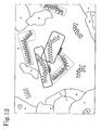
- Fig. 12 shows an example of applying Mode 1.
- the corresponding pattern specific display creating means 44b creates a "nonconforming pattern display” (green) when a nonconforming result is outputted.
- the nonconforming pattern display is only of one kind (green).
- the recognized data display creating means 44c creates a "nonconforming step display" from the "nonconforming result” and "nonconforming code symbol image” to display the not passed step. For example, "The third check step was not passed” and the like are preferable.
- the corresponding pattern specific display creating means 44b creates a "corresponding pattern specific display” and the recognized data display means 44c creates a recognized data display.
- the aftermentioned Figs. 11 and 12 will show examples of the displays.
- step S5-5 which checks whether the obtained regions have all been determined. If the determination for all regions is finished, the process moves on to the step S5-6.
- the compositing means 44d superimposes the corresponding pattern specific display, nonconforming pattern display, recognized data display and nonconforming step display, created so far, on the original image (code symbol image), and the displaying means 16 displays the composited display.
- superimposition of images may also be performed at each time that a display is created.
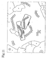
- Fig. 11 shows a display example of only superimposing a corresponding pattern specific display and a recognized data display on the original image (code symbol image).
- rectangular displays enclosing the finally recognized code symbols (corresponding pattern specific display) are displayed in such a manner as superimposed on the original image (code symbol image).
- Fig. 12 shows an example of displaying the nonconforming pattern displays created in the above step S5-10, superimposed on the display of Fig. 11 .
- three area groups (see the regions marked with " ⁇ " in Fig. 10 ) excluded from the code candidate regions for not meeting the condition in the step S5-9, are displayed with dashed rectangles, by virtue of which, the operator can easily know that these three area groups were proved nonconforming in the step S5-9.
- Part 5-2 Utilizing the nonconforming pattern display in searching Further, in Part 4, there is described an example of searching for code symbols as specific search objects. In such case, it is also preferable to display the nonconforming pattern display described in Part 5 for the unrecognizable code symbols.
- Part 6 In combination use with RFID tags
- RFID tags utilize radio waves for readers to read out predetermined digital data, and are among the automatic recognition code symbols applicable to ID control for articles by tagging each article.
- a characteristic of the RFID tag exists in that a plurality of the tags can be read out simultaneously even at such a position as becoming a hidden shadow from the reader by virtue of the mechanism of reading out data through radio waves.
- RFID tags are commonly not assumed to be recognized with the unaided eye. This means, as a result, that when the data cannot be read out, because the tag cannot be recognized with the unaided eye, the existence of the RFID tag, that is, the existence of the article itself tagged with the RFID tag will not be able to be recognized.
- the apparatus it is practicable to use an apparatus able to read out both RFID tag and 1D color bit code. It is preferable for the apparatus to compare the data read out of the RFID tag with the data obtained by recognizing the 1D color bit code, and then perform a display indicating the result (whether conforming to each other or not).
- the conforming data is displayed in green characters as the "recognized data display";
- the 1D color bit code data is displayed in red characters as the "recognized data display".
- the data is displayed in red characters as the "data display".
- the so-called RFID tags can be any tags that transmit and receive data through radio waves.
- RFID tags also referred to as RF tags at times
- RF tags can be any tags that transmit and receive data through radio waves.
- wireless tags, IC tags and the like are also included.
- the image data are basically premised on digital image data. Therefore, it is preferable to carry out the process by means of hardware and software capable of processing such image data.
- means in the computer 14 described above be established by a program realizing each means and a computer 14 executing the program.
- the optical recognition code recognizer described in the embodiment mainly, comprises a camera means, a computer 14, a displaying means 16 in correspondence therewith and the like.
- the recognizer may be configured by the above components either in a separate manner or in an integrated manner.
- the recognizer is also preferably configured by a CCD camera and a personal computer. Further, it is yet preferable to be configured by a PDA or a handheld terminal provided with a camera means, or even by a handheld communication terminal such as a cell-phone, etc., provided with a camera means.
- 1D color bit codes were taken as an example in the description; however, it is also possible, of course, to apply the present invention to other optical recognition codes.
Landscapes
- Physics & Mathematics (AREA)
- Engineering & Computer Science (AREA)
- General Physics & Mathematics (AREA)
- Theoretical Computer Science (AREA)
- General Health & Medical Sciences (AREA)
- Electromagnetism (AREA)
- Health & Medical Sciences (AREA)
- Toxicology (AREA)
- Artificial Intelligence (AREA)
- Computer Vision & Pattern Recognition (AREA)
- Character Discrimination (AREA)
- Character Input (AREA)
- Editing Of Facsimile Originals (AREA)
- User Interface Of Digital Computer (AREA)
Applications Claiming Priority (2)
| Application Number | Priority Date | Filing Date | Title |
|---|---|---|---|
| JP2007142145A JP2008299412A (ja) | 2007-05-29 | 2007-05-29 | 光学式認識コード認識結果表示方法 |
| PCT/JP2008/058518 WO2008146580A1 (ja) | 2007-05-29 | 2008-05-08 | 光学式認識コード認識結果表示方法 |
Publications (1)
| Publication Number | Publication Date |
|---|---|
| EP2154629A1 true EP2154629A1 (en) | 2010-02-17 |
Family
ID=40074849
Family Applications (1)
| Application Number | Title | Priority Date | Filing Date |
|---|---|---|---|
| EP08752409A Withdrawn EP2154629A1 (en) | 2007-05-29 | 2008-05-08 | Optical recognition code recognized result displaying method |
Country Status (5)
| Country | Link |
|---|---|
| US (1) | US20100096457A1 (enExample) |
| EP (1) | EP2154629A1 (enExample) |
| JP (1) | JP2008299412A (enExample) |
| TW (1) | TW200910224A (enExample) |
| WO (1) | WO2008146580A1 (enExample) |
Families Citing this family (6)
| Publication number | Priority date | Publication date | Assignee | Title |
|---|---|---|---|---|
| WO2009060942A1 (ja) * | 2007-11-09 | 2009-05-14 | B-Core Inc. | 光学式認識コード及びそのマーキング方法及びその読み取り方法、並びに、光学式認識コードをマーキングした物品、並びに、色彩認識方法及びプログラム、並びに、色彩配列による自動認識コード及びそれが付された物品 |
| JP2011165139A (ja) * | 2010-02-15 | 2011-08-25 | Toshiba Tec Corp | コードシンボル読取装置及び制御プログラム |
| DE102010033181A1 (de) * | 2010-08-03 | 2012-02-09 | Eppendorf Ag | Verfahren zum Wiedererkennen eines verwechselbaren Gegenstands |
| JP5609704B2 (ja) * | 2011-02-18 | 2014-10-22 | 株式会社デンソーウェーブ | 非接触通信媒体読取装置 |
| JP6406539B2 (ja) * | 2014-07-11 | 2018-10-17 | サトーホールディングス株式会社 | 電子黒板 |
| WO2022074955A1 (ja) * | 2020-10-05 | 2022-04-14 | パナソニックIpマネジメント株式会社 | 情報取得装置、情報取得プログラム、および情報取得方法 |
Family Cites Families (12)
| Publication number | Priority date | Publication date | Assignee | Title |
|---|---|---|---|---|
| JPS63228278A (ja) * | 1987-03-17 | 1988-09-22 | Fujitsu Ltd | 光学式マ−ク読取り可能なocr装置 |
| JPH06243340A (ja) * | 1993-02-18 | 1994-09-02 | Hitachi Ltd | セルフチェックアウトシステム |
| JPH08185463A (ja) | 1994-12-28 | 1996-07-16 | Pentel Kk | バ−コ−ド切り出し方法 |
| JPH08305785A (ja) | 1995-04-28 | 1996-11-22 | Matsushita Electric Ind Co Ltd | バーコード読み取り装置 |
| JP2001028033A (ja) * | 1999-07-14 | 2001-01-30 | Oki Electric Ind Co Ltd | バーコード認識結果の表示方法およびバーコード認識装置 |
| JP2004110670A (ja) * | 2002-09-20 | 2004-04-08 | Denso Wave Inc | 情報コード読取装置 |
| JP2005193578A (ja) | 2004-01-09 | 2005-07-21 | Canon Inc | 印刷方式 |
| JP2005266907A (ja) | 2004-03-16 | 2005-09-29 | Toshiba Social Automation Systems Co Ltd | バーコード検出切り出し方法及びその装置、並びにプログラムを格納したコンピュータ読み取り可能な記録媒体 |
| JP4301055B2 (ja) * | 2004-03-29 | 2009-07-22 | カシオ計算機株式会社 | データ処理装置及びプログラム |
| JP4755415B2 (ja) * | 2004-12-21 | 2011-08-24 | 株式会社アドイン研究所 | カラー二次元コード |
| JP2006196705A (ja) | 2005-01-13 | 2006-07-27 | Tokyo Ohka Kogyo Co Ltd | 回路素子の形成方法および多層回路素子 |
| JP4364247B2 (ja) | 2007-02-05 | 2009-11-11 | ユニ・チャーム株式会社 | 吸収性物品 |
-
2007
- 2007-05-29 JP JP2007142145A patent/JP2008299412A/ja not_active Withdrawn
-
2008
- 2008-05-08 WO PCT/JP2008/058518 patent/WO2008146580A1/ja not_active Ceased
- 2008-05-08 EP EP08752409A patent/EP2154629A1/en not_active Withdrawn
- 2008-05-08 US US12/451,251 patent/US20100096457A1/en not_active Abandoned
- 2008-05-20 TW TW097118572A patent/TW200910224A/zh unknown
Non-Patent Citations (1)
| Title |
|---|
| See references of WO2008146580A1 * |
Also Published As
| Publication number | Publication date |
|---|---|
| TW200910224A (en) | 2009-03-01 |
| US20100096457A1 (en) | 2010-04-22 |
| WO2008146580A1 (ja) | 2008-12-04 |
| JP2008299412A (ja) | 2008-12-11 |
Similar Documents
| Publication | Publication Date | Title |
|---|---|---|
| US6942151B2 (en) | Optical reader having decoding and image capturing functionality | |
| EP2154629A1 (en) | Optical recognition code recognized result displaying method | |
| US7111787B2 (en) | Multimode image capturing and decoding optical reader | |
| USRE44139E1 (en) | Method and apparatus for decoding mixed code | |
| USRE44982E1 (en) | Mixed code, and method and apparatus for generating the same | |
| US5841900A (en) | Method for graph-based table recognition | |
| US6983886B2 (en) | Two-dimensional code reader setting method, two-dimensional code reader, two dimensional code reader setting program and computer readable recording medium | |
| US8879832B2 (en) | Color matrix code | |
| US20140119647A1 (en) | Method and Apparatus for Decoding Mixed Code | |
| CN111738901B (zh) | 存储介质以及图像处理装置 | |
| US20030102376A1 (en) | Image device having indicia-controlled image parsing mode | |
| US20210397798A1 (en) | Information processing apparatus and non-transitory computer readable medium | |
| US20230037838A1 (en) | Method of optically reading information code and control of the method | |
| CN101088100A (zh) | 混合码,产生混合码的方法和装置,以及对混合码进行解码的方法和装置 | |
| HK1204308A1 (en) | Systems and methods for label creation using object recognition | |
| CN109710264A (zh) | Gerber文件转化方法、系统、设备及存储介质 | |
| US12190632B2 (en) | Method, apparatus, device and storage medium for detecting a card surface picture | |
| US6611274B1 (en) | System method, and computer program product for compositing true colors and intensity-maped colors into a frame buffer | |
| US20230410388A1 (en) | Labeling device, labeling method, labeling program, and recording medium | |
| CN105069393A (zh) | 二维码防恶意读取方法及装置 | |
| JPS6245581B2 (enExample) | ||
| JP7231844B2 (ja) | 情報処理装置、情報処理方法、プログラム | |
| CN120409510A (zh) | 一种条码解码方法和装置 | |
| Mohd Zamri | Indoor Localization and Guidance using Augmented Reality Toolbox | |
| JPH045779A (ja) | 文字認識装置 |
Legal Events
| Date | Code | Title | Description |
|---|---|---|---|
| PUAI | Public reference made under article 153(3) epc to a published international application that has entered the european phase |
Free format text: ORIGINAL CODE: 0009012 |
|
| 17P | Request for examination filed |
Effective date: 20091130 |
|
| AK | Designated contracting states |
Kind code of ref document: A1 Designated state(s): AT BE BG CH CY CZ DE DK EE ES FI FR GB GR HR HU IE IS IT LI LT LU LV MC MT NL NO PL PT RO SE SI SK TR |
|
| AX | Request for extension of the european patent |
Extension state: AL BA MK RS |
|
| STAA | Information on the status of an ep patent application or granted ep patent |
Free format text: STATUS: THE APPLICATION HAS BEEN WITHDRAWN |
|
| 18W | Application withdrawn |
Effective date: 20100309 |