EP2154042A1 - Driving force control device for vehicle - Google Patents
Driving force control device for vehicle Download PDFInfo
- Publication number
- EP2154042A1 EP2154042A1 EP08740832A EP08740832A EP2154042A1 EP 2154042 A1 EP2154042 A1 EP 2154042A1 EP 08740832 A EP08740832 A EP 08740832A EP 08740832 A EP08740832 A EP 08740832A EP 2154042 A1 EP2154042 A1 EP 2154042A1
- Authority
- EP
- European Patent Office
- Prior art keywords
- output
- alternator
- electric generator
- electric power
- driving force
- Prior art date
- Legal status (The legal status is an assumption and is not a legal conclusion. Google has not performed a legal analysis and makes no representation as to the accuracy of the status listed.)
- Granted
Links
Images










Classifications
-
- B—PERFORMING OPERATIONS; TRANSPORTING
- B60—VEHICLES IN GENERAL
- B60W—CONJOINT CONTROL OF VEHICLE SUB-UNITS OF DIFFERENT TYPE OR DIFFERENT FUNCTION; CONTROL SYSTEMS SPECIALLY ADAPTED FOR HYBRID VEHICLES; ROAD VEHICLE DRIVE CONTROL SYSTEMS FOR PURPOSES NOT RELATED TO THE CONTROL OF A PARTICULAR SUB-UNIT
- B60W20/00—Control systems specially adapted for hybrid vehicles
- B60W20/10—Controlling the power contribution of each of the prime movers to meet required power demand
-
- B—PERFORMING OPERATIONS; TRANSPORTING
- B60—VEHICLES IN GENERAL
- B60K—ARRANGEMENT OR MOUNTING OF PROPULSION UNITS OR OF TRANSMISSIONS IN VEHICLES; ARRANGEMENT OR MOUNTING OF PLURAL DIVERSE PRIME-MOVERS IN VEHICLES; AUXILIARY DRIVES FOR VEHICLES; INSTRUMENTATION OR DASHBOARDS FOR VEHICLES; ARRANGEMENTS IN CONNECTION WITH COOLING, AIR INTAKE, GAS EXHAUST OR FUEL SUPPLY OF PROPULSION UNITS IN VEHICLES
- B60K6/00—Arrangement or mounting of plural diverse prime-movers for mutual or common propulsion, e.g. hybrid propulsion systems comprising electric motors and internal combustion engines
- B60K6/20—Arrangement or mounting of plural diverse prime-movers for mutual or common propulsion, e.g. hybrid propulsion systems comprising electric motors and internal combustion engines the prime-movers consisting of electric motors and internal combustion engines, e.g. HEVs
- B60K6/42—Arrangement or mounting of plural diverse prime-movers for mutual or common propulsion, e.g. hybrid propulsion systems comprising electric motors and internal combustion engines the prime-movers consisting of electric motors and internal combustion engines, e.g. HEVs characterised by the architecture of the hybrid electric vehicle
- B60K6/44—Series-parallel type
-
- B—PERFORMING OPERATIONS; TRANSPORTING
- B60—VEHICLES IN GENERAL
- B60K—ARRANGEMENT OR MOUNTING OF PROPULSION UNITS OR OF TRANSMISSIONS IN VEHICLES; ARRANGEMENT OR MOUNTING OF PLURAL DIVERSE PRIME-MOVERS IN VEHICLES; AUXILIARY DRIVES FOR VEHICLES; INSTRUMENTATION OR DASHBOARDS FOR VEHICLES; ARRANGEMENTS IN CONNECTION WITH COOLING, AIR INTAKE, GAS EXHAUST OR FUEL SUPPLY OF PROPULSION UNITS IN VEHICLES
- B60K6/00—Arrangement or mounting of plural diverse prime-movers for mutual or common propulsion, e.g. hybrid propulsion systems comprising electric motors and internal combustion engines
- B60K6/20—Arrangement or mounting of plural diverse prime-movers for mutual or common propulsion, e.g. hybrid propulsion systems comprising electric motors and internal combustion engines the prime-movers consisting of electric motors and internal combustion engines, e.g. HEVs
- B60K6/50—Architecture of the driveline characterised by arrangement or kind of transmission units
- B60K6/52—Driving a plurality of drive axles, e.g. four-wheel drive
-
- B—PERFORMING OPERATIONS; TRANSPORTING
- B60—VEHICLES IN GENERAL
- B60L—PROPULSION OF ELECTRICALLY-PROPELLED VEHICLES; SUPPLYING ELECTRIC POWER FOR AUXILIARY EQUIPMENT OF ELECTRICALLY-PROPELLED VEHICLES; ELECTRODYNAMIC BRAKE SYSTEMS FOR VEHICLES IN GENERAL; MAGNETIC SUSPENSION OR LEVITATION FOR VEHICLES; MONITORING OPERATING VARIABLES OF ELECTRICALLY-PROPELLED VEHICLES; ELECTRIC SAFETY DEVICES FOR ELECTRICALLY-PROPELLED VEHICLES
- B60L15/00—Methods, circuits, or devices for controlling the traction-motor speed of electrically-propelled vehicles
- B60L15/20—Methods, circuits, or devices for controlling the traction-motor speed of electrically-propelled vehicles for control of the vehicle or its driving motor to achieve a desired performance, e.g. speed, torque, programmed variation of speed
-
- B—PERFORMING OPERATIONS; TRANSPORTING
- B60—VEHICLES IN GENERAL
- B60L—PROPULSION OF ELECTRICALLY-PROPELLED VEHICLES; SUPPLYING ELECTRIC POWER FOR AUXILIARY EQUIPMENT OF ELECTRICALLY-PROPELLED VEHICLES; ELECTRODYNAMIC BRAKE SYSTEMS FOR VEHICLES IN GENERAL; MAGNETIC SUSPENSION OR LEVITATION FOR VEHICLES; MONITORING OPERATING VARIABLES OF ELECTRICALLY-PROPELLED VEHICLES; ELECTRIC SAFETY DEVICES FOR ELECTRICALLY-PROPELLED VEHICLES
- B60L50/00—Electric propulsion with power supplied within the vehicle
- B60L50/10—Electric propulsion with power supplied within the vehicle using propulsion power supplied by engine-driven generators, e.g. generators driven by combustion engines
- B60L50/16—Electric propulsion with power supplied within the vehicle using propulsion power supplied by engine-driven generators, e.g. generators driven by combustion engines with provision for separate direct mechanical propulsion
-
- B—PERFORMING OPERATIONS; TRANSPORTING
- B60—VEHICLES IN GENERAL
- B60W—CONJOINT CONTROL OF VEHICLE SUB-UNITS OF DIFFERENT TYPE OR DIFFERENT FUNCTION; CONTROL SYSTEMS SPECIALLY ADAPTED FOR HYBRID VEHICLES; ROAD VEHICLE DRIVE CONTROL SYSTEMS FOR PURPOSES NOT RELATED TO THE CONTROL OF A PARTICULAR SUB-UNIT
- B60W10/00—Conjoint control of vehicle sub-units of different type or different function
- B60W10/04—Conjoint control of vehicle sub-units of different type or different function including control of propulsion units
- B60W10/08—Conjoint control of vehicle sub-units of different type or different function including control of propulsion units including control of electric propulsion units, e.g. motors or generators
-
- B—PERFORMING OPERATIONS; TRANSPORTING
- B60—VEHICLES IN GENERAL
- B60L—PROPULSION OF ELECTRICALLY-PROPELLED VEHICLES; SUPPLYING ELECTRIC POWER FOR AUXILIARY EQUIPMENT OF ELECTRICALLY-PROPELLED VEHICLES; ELECTRODYNAMIC BRAKE SYSTEMS FOR VEHICLES IN GENERAL; MAGNETIC SUSPENSION OR LEVITATION FOR VEHICLES; MONITORING OPERATING VARIABLES OF ELECTRICALLY-PROPELLED VEHICLES; ELECTRIC SAFETY DEVICES FOR ELECTRICALLY-PROPELLED VEHICLES
- B60L2240/00—Control parameters of input or output; Target parameters
- B60L2240/40—Drive Train control parameters
- B60L2240/42—Drive Train control parameters related to electric machines
- B60L2240/423—Torque
-
- B—PERFORMING OPERATIONS; TRANSPORTING
- B60—VEHICLES IN GENERAL
- B60W—CONJOINT CONTROL OF VEHICLE SUB-UNITS OF DIFFERENT TYPE OR DIFFERENT FUNCTION; CONTROL SYSTEMS SPECIALLY ADAPTED FOR HYBRID VEHICLES; ROAD VEHICLE DRIVE CONTROL SYSTEMS FOR PURPOSES NOT RELATED TO THE CONTROL OF A PARTICULAR SUB-UNIT
- B60W20/00—Control systems specially adapted for hybrid vehicles
-
- B—PERFORMING OPERATIONS; TRANSPORTING
- B60—VEHICLES IN GENERAL
- B60W—CONJOINT CONTROL OF VEHICLE SUB-UNITS OF DIFFERENT TYPE OR DIFFERENT FUNCTION; CONTROL SYSTEMS SPECIALLY ADAPTED FOR HYBRID VEHICLES; ROAD VEHICLE DRIVE CONTROL SYSTEMS FOR PURPOSES NOT RELATED TO THE CONTROL OF A PARTICULAR SUB-UNIT
- B60W2510/00—Input parameters relating to a particular sub-units
- B60W2510/08—Electric propulsion units
-
- B—PERFORMING OPERATIONS; TRANSPORTING
- B60—VEHICLES IN GENERAL
- B60W—CONJOINT CONTROL OF VEHICLE SUB-UNITS OF DIFFERENT TYPE OR DIFFERENT FUNCTION; CONTROL SYSTEMS SPECIALLY ADAPTED FOR HYBRID VEHICLES; ROAD VEHICLE DRIVE CONTROL SYSTEMS FOR PURPOSES NOT RELATED TO THE CONTROL OF A PARTICULAR SUB-UNIT
- B60W2710/00—Output or target parameters relating to a particular sub-units
- B60W2710/08—Electric propulsion units
-
- B—PERFORMING OPERATIONS; TRANSPORTING
- B60—VEHICLES IN GENERAL
- B60W—CONJOINT CONTROL OF VEHICLE SUB-UNITS OF DIFFERENT TYPE OR DIFFERENT FUNCTION; CONTROL SYSTEMS SPECIALLY ADAPTED FOR HYBRID VEHICLES; ROAD VEHICLE DRIVE CONTROL SYSTEMS FOR PURPOSES NOT RELATED TO THE CONTROL OF A PARTICULAR SUB-UNIT
- B60W2710/00—Output or target parameters relating to a particular sub-units
- B60W2710/08—Electric propulsion units
- B60W2710/083—Torque
-
- B—PERFORMING OPERATIONS; TRANSPORTING
- B60—VEHICLES IN GENERAL
- B60W—CONJOINT CONTROL OF VEHICLE SUB-UNITS OF DIFFERENT TYPE OR DIFFERENT FUNCTION; CONTROL SYSTEMS SPECIALLY ADAPTED FOR HYBRID VEHICLES; ROAD VEHICLE DRIVE CONTROL SYSTEMS FOR PURPOSES NOT RELATED TO THE CONTROL OF A PARTICULAR SUB-UNIT
- B60W2710/00—Output or target parameters relating to a particular sub-units
- B60W2710/24—Energy storage means
-
- Y—GENERAL TAGGING OF NEW TECHNOLOGICAL DEVELOPMENTS; GENERAL TAGGING OF CROSS-SECTIONAL TECHNOLOGIES SPANNING OVER SEVERAL SECTIONS OF THE IPC; TECHNICAL SUBJECTS COVERED BY FORMER USPC CROSS-REFERENCE ART COLLECTIONS [XRACs] AND DIGESTS
- Y02—TECHNOLOGIES OR APPLICATIONS FOR MITIGATION OR ADAPTATION AGAINST CLIMATE CHANGE
- Y02T—CLIMATE CHANGE MITIGATION TECHNOLOGIES RELATED TO TRANSPORTATION
- Y02T10/00—Road transport of goods or passengers
- Y02T10/60—Other road transportation technologies with climate change mitigation effect
- Y02T10/62—Hybrid vehicles
-
- Y—GENERAL TAGGING OF NEW TECHNOLOGICAL DEVELOPMENTS; GENERAL TAGGING OF CROSS-SECTIONAL TECHNOLOGIES SPANNING OVER SEVERAL SECTIONS OF THE IPC; TECHNICAL SUBJECTS COVERED BY FORMER USPC CROSS-REFERENCE ART COLLECTIONS [XRACs] AND DIGESTS
- Y02—TECHNOLOGIES OR APPLICATIONS FOR MITIGATION OR ADAPTATION AGAINST CLIMATE CHANGE
- Y02T—CLIMATE CHANGE MITIGATION TECHNOLOGIES RELATED TO TRANSPORTATION
- Y02T10/00—Road transport of goods or passengers
- Y02T10/60—Other road transportation technologies with climate change mitigation effect
- Y02T10/64—Electric machine technologies in electromobility
-
- Y—GENERAL TAGGING OF NEW TECHNOLOGICAL DEVELOPMENTS; GENERAL TAGGING OF CROSS-SECTIONAL TECHNOLOGIES SPANNING OVER SEVERAL SECTIONS OF THE IPC; TECHNICAL SUBJECTS COVERED BY FORMER USPC CROSS-REFERENCE ART COLLECTIONS [XRACs] AND DIGESTS
- Y02—TECHNOLOGIES OR APPLICATIONS FOR MITIGATION OR ADAPTATION AGAINST CLIMATE CHANGE
- Y02T—CLIMATE CHANGE MITIGATION TECHNOLOGIES RELATED TO TRANSPORTATION
- Y02T10/00—Road transport of goods or passengers
- Y02T10/60—Other road transportation technologies with climate change mitigation effect
- Y02T10/70—Energy storage systems for electromobility, e.g. batteries
-
- Y—GENERAL TAGGING OF NEW TECHNOLOGICAL DEVELOPMENTS; GENERAL TAGGING OF CROSS-SECTIONAL TECHNOLOGIES SPANNING OVER SEVERAL SECTIONS OF THE IPC; TECHNICAL SUBJECTS COVERED BY FORMER USPC CROSS-REFERENCE ART COLLECTIONS [XRACs] AND DIGESTS
- Y02—TECHNOLOGIES OR APPLICATIONS FOR MITIGATION OR ADAPTATION AGAINST CLIMATE CHANGE
- Y02T—CLIMATE CHANGE MITIGATION TECHNOLOGIES RELATED TO TRANSPORTATION
- Y02T10/00—Road transport of goods or passengers
- Y02T10/60—Other road transportation technologies with climate change mitigation effect
- Y02T10/7072—Electromobility specific charging systems or methods for batteries, ultracapacitors, supercapacitors or double-layer capacitors
-
- Y—GENERAL TAGGING OF NEW TECHNOLOGICAL DEVELOPMENTS; GENERAL TAGGING OF CROSS-SECTIONAL TECHNOLOGIES SPANNING OVER SEVERAL SECTIONS OF THE IPC; TECHNICAL SUBJECTS COVERED BY FORMER USPC CROSS-REFERENCE ART COLLECTIONS [XRACs] AND DIGESTS
- Y02—TECHNOLOGIES OR APPLICATIONS FOR MITIGATION OR ADAPTATION AGAINST CLIMATE CHANGE
- Y02T—CLIMATE CHANGE MITIGATION TECHNOLOGIES RELATED TO TRANSPORTATION
- Y02T10/00—Road transport of goods or passengers
- Y02T10/60—Other road transportation technologies with climate change mitigation effect
- Y02T10/72—Electric energy management in electromobility
Definitions
- the present invention relates to a driving force controlling apparatus for a vehicle, and particularly to a driving force controlling apparatus for a vehicle including a motor for driving wheels other than driving wheels driven by an engine, with electric power from an electric generator.
- a driving force controlling apparatus for a vehicle including a motor for driving wheels other than driving wheels driven by an engine, with electric power from an electric generator is known conventionally.
- an AC motor electric 4WD including an AC motor existing on a non-engine shaft and driven by electric power from an alternator a request is made of the alternator to generate electric power necessary for the motor.
- a technique for causing the alternator to stably output the requested voltage to enable the motor to operate stably there is a demand for a technique for causing the alternator to stably output the requested voltage to enable the motor to operate stably.
- Patent Document 1 Japanese Patent Application Laid-open No. 2006-206040
- an upper limit voltage of the alternator is set at a predetermined value (42V in this example) as in a 42V alternator, for example, which is under consideration or employed in the motor vehicle industry, and if greater electric power than that the alternator can output stably is requested of the alternator, the alternator cannot stably output the electric power.
- a driving force controlling apparatus for a vehicle including an electric generator and a motor for driving a wheel other than a driving wheel, with electric power from the electric generator
- the driving force controlling apparatus includes a requested electric power computing means that computes requested electric power required for operation of the motor, wherein target output of the electric generator is set based on the requested electric power and maximum output that the electric generator is capable of outputting stably.
- the stable maximum output of the electric generator is set based on an upper limit voltage of the electric generator.
- the stable maximum output of the electric generator is set based on a stable output line obtained from maximum outputs at different internal electromotive voltages of the electric generator.
- output of the electric generator is increased in such a manner as to move on an efficiency line set in advance in consideration of efficiency, when output of the electric generator is increased to the target output.
- the efficiency line is set based on at least one of efficiency of the electric generator, efficiency of an inverter between the electric generator and the motor, and efficiency of the motor.
- output of the electric generator is increased in such a manner as to move on a stable output line obtained from maximum outputs at different internal electromotive voltages of the electric generator, when output of the electric generator is increased to the target output.
- the driving force controlling apparatus for a vehicle including the motor for driving the wheels other than the driving wheels driven by the engine, with the electric power of the electric generator, can enable the electric generator to stably output electric power.
- Fig. 2 depicts a schematic constitution of the present embodiment.
- the schematic constitution includes an AC motor 104 for driving a non-engine shaft 103 other than a shaft 102 driven by an engine 101, an alternator 106 connected to the engine 101 via a belt 105 to supply electric power to the AC motor 104, an inverter 107 for converting DC power generated by the alternator 106 into AC power, and means 109 for changing a rotation ratio between the engine 101 and tires 108 (irrespective of CVT, AT, or MMT).
- the present embodiment relates to a method of controlling the alternator 106 in an AC motor electric 4WD including the AC motor 104 existing on the non-engine shaft 103 and driven with the electric power from the alternator 106.
- the alternator 106 cannot stably output the electric power. It is an object of the embodiment to solve this problem.
- step S100 a motor torque command value Tm representing torque that the motor 104 should output is calculated by using a preset map or the like according to a traveling condition of a vehicle.
- step S110 an electric power Palt requested of the alternator and representing electric power required to output the motor torque command value Tm is calculated.
- the electric power requested of the alternator 106 (the electric power Palt requested of the alternator) is obtained.
- step S120 whether or not the electric power Palt requested of the alternator is greater than a stable maximum output Pmax is determined. If the electric power Palt requested of the alternator is determined to be greater than the stable maximum output Pmax as a result of the determination, the control goes to step S130. If not, the control goes to step S140.
- the stable maximum output Pmax is retained as a map in advance.
- the stable maximum output Pmax is electric power at an intersection point of a stable limit electric power line SL and an upper limit voltage Vmax.
- the stable limit electric power line SL is obtained as follows.
- the internal electromotive voltage E is expressed by the following expression (2).
- E n * d ⁇ dt ⁇ n * If * Nalt
- n is the number of stator turns
- ⁇ is magnetic flux
- If is an excitation current
- Nalt is a rotational speed of the alternator 106.
- Fig. 5 illustrating the V-P characteristic of the alternator 106.
- the alternator 106 is operated at a point "a" or a point "b".
- the stable limit electric power line SL is obtained by changing a value of the internal electromotive force E and connecting the respective maximum values Pm of the output P of the alternator 106. If the voltage is greater than the stable limit electric power line SL, it is possible to stably output the requested electric power.
- the line connecting the maximum values Pm of the output P of the alternator 106 is defined as the stable electric power limit line, it is also possible to set a margin to make allowance.
- the stable limit electric power line SL and the stable maximum output Pmax are also stored for each rotational speed Nalt of the alternator 106 (See Figs. 8 and 9 . Nalt is low in Fig. 8 and high in Fig. 9 ). Therefore, the stable maximum output Pmax is stored in a map together with the rotational speed Nalt of the alternator 106. Accordingly, in step S120, the rotational speed Nalt of the alternator 106 is detected, and the Pmax is obtained from the map and compared with the Palt.
- step S130 a target alternator output Pout is set at the stable maximum output Pmax. If the electric power Palt requested of the alternator is greater than the stable maximum output Pmax (step S120-Y), the electric power greater than the maximum electric power (stable maximum output Pmax) that the alternator 106 can output stably is requested. In this case, the target alternator output Pout is set at the stable maximum output Pmax so that the alternator 106 can output stably. Following step S130, the control goes to step S150.
- step S140 the target alternator output Pout is set at the electric power Palt requested of the alternator. If the electric power Palt requested of the alternator is equal to or smaller than the stable maximum output Pmax (step S120-N), the electric power requested of the alternator 106 (the electric power Palt requested of the alternator) is in such a range that the alternator 106 can output it stably. In this case, the target alternator output Pout is set at the electric power Palt requested of the alternator. Following step S140, the control goes to step S150.
- step S150 the present output Pt of the alternator 106 and the target alternator output Pout are compared with each other to determine whether or not an end condition of this control is satisfied. Whether or not the present output Pt of the alternator 106 is smaller than the target alternator output Pout is determined. If the present output Pt of the alternator 106 is smaller than the target alternator output Pout as a result of the determination, the control goes to step S160. If not, this control ends.
- step S160 the present output Pt of the alternator 106 is increased to move on a maximum efficiency line EL.
- step S150-Y If the present output Pt of the alternator 106 is smaller than the target alternator output Pout (step S150-Y), the inverter 107 requests the alternator 106 to increase the present output Pt of the alternator 106. At this time, the present output Pt of the alternator 106 is increased while controlling the excitation current to control the voltage so that the output moves on the maximum efficiency line EL obtained in advance.
- a method of obtaining the maximum efficiency line EL (the most efficient course considering collectively from the alternator 106 to the motor 104) when the rotational speed Nalt of the alternator 106, a rotational speed Nmot of the motor 104, torque Tmot of the motor 104 are fixed will be shown below.
- Total efficiency ⁇ is obtained by multiplying efficiency ⁇ alt of the alternator 106 by efficiency ⁇ inv of the inverter 107 and efficiency ⁇ mot of the motor 104 (the following expression 3).
- Expression 3 ⁇ ⁇ alt * ⁇ inv * ⁇ mot
- the range in which the target alternator output Pout can be output stably is a portion shown with an arrow Y2 in Figs. 10 and 11 (the range in which the voltage is higher than the stable limit electric power line SL).
- the output electric power P of the alternator 106 is changed (P1, P2, P3 %) and points Q (Q1, Q2, Q3 %) with the maximum total efficiency ⁇ in the ranges Y2 in which the target alternator output Pout can be output stably for the respective values of the output electric power P (P1, P2, P3 ...) of the alternator 106 are connected to thereby obtain the maximum efficiency line EL.
- the maximum efficiency line EL is obtained based on the total efficiency ⁇ that is the product of the efficiency ⁇ alt of the alternator 106, the efficiency ⁇ inv of the inverter 107, and the efficiency ⁇ mot of the motor 104 in the embodiment, the maximum efficiency line EL can be obtained based on at least one of the efficiency ⁇ alt of the alternator 106, the efficiency ⁇ inv of the inverter 107, and the efficiency ⁇ mot of the motor 104 or based on the product of two of them.
- Fig. 12 shows a V- ⁇ alt characteristic in the range Y2 in which the alternator 106 in the example can stably output the target alternator output Pout.
- Fig. 13 shows a V- ⁇ mot characteristic of the inverter 107 when the rotational speed and torque of the motor 104 are fixed. The lower the voltage is, the higher the efficiency of the inverter 107 becomes.
- Fig. 14 shows a V- ⁇ mot characteristic of the motor 104 when the rotational speed and torque of the motor 104 are fixed.
- the efficiency of the motor 104 hardly depends on the voltage.
- step S170 the motor torque is applied by using the present output Pt of the alternator 106.
- the AC motor 104 is driven and the torque is applied.
- step S170 the control returns to step S150. Thereafter, by repeating the operations in steps S150 to S170, motor torque according to the motor torque command value is output.
- the present embodiment relates to the method of controlling the alternator 106 in the AC motor electric 4WD including the AC motor 104 existing on the non-engine shaft and driven with the electric power from the alternator 106.
- There is the limit Pmax to the electric power that the alternator 106 can output stably depending on voltage. Therefore, if the upper limit voltage Vmax is determined and requested electric power Palt is excessively large, it is impossible to output it stably. Therefore, if the electric power Palt requested of the alternator is excessively large (step S120-Y), the alternator 106 outputs the maximum electric power Pmax (Pout Pmax) that it can output stably and the motor torque is suppressed according to the electric power.
- step S120 the stability (step S120), the requested electric power (step S140), and the efficiency (step S160) are weighted in this order in controlling the alternator 106.
- the efficiency is taken into consideration in the present embodiment.
- the present output Pt is increased to move on the maximum efficiency line EL (step S150 in Fig. 1 ).
- control is carried out while keeping target voltage Vout constant in consideration of ease of control in increasing the present output Pt.
- step S130 similar to that in the first embodiment, the target alternator output Pout is set at the stable maximum output Pmax. Then, in step S131, the target voltage Vout is set at the upper limit voltage Vmax (see Fig. 17 ). Following step S131, the control goes to step S150.
- step S140 similar to that in the first embodiment, the target alternator output Pout is set at the electric power Palt requested of the alternator. Then, in step S141, an intersection point A of a constant electric power line of the electric power Palt requested of the alternator and the stable limit electric power line SL is calculated as shown in Fig. 18 .
- step S142 the efficient voltage Ve in a range from voltage Va corresponding to the intersection point A obtained in step S141 to the upper limit voltage Vmax is calculated (see Fig. 18 ).
- the most efficient voltage Ve is selected considering collectively from the alternator 106 to the motor 104.
- step S143 the target voltage Vout is set at the voltage Ve (see Fig. 18 ). Because the output is stable at any voltage between the voltage Va and the upper limit voltage Vmax, the target voltage Vout may be set at the voltage Va or at the voltage Vmax to omit calculation of efficiency. Following step S143, the control goes to step S150.
- step S150 similarly to the first embodiment, whether or not the present output Pt is smaller than the target alternator output Pout is determined. If the present output Pt is smaller than the target alternator output Pout as a result of determination, the control goes to step S161. If not, the control ends.
- step S161 the present output Pt is increased while controlling an excitation current and keeping the target voltage Vout constant (see arrows Y3, Y4 in Figs. 17, 18 ).
- step S170 similarly to the first embodiment, motor torque is generated by using the present output Pt. After step S170, steps from S150 to S170 are repeated until the result of the determination in step S150 becomes negative.
- the target alternator output Pout is determined based on the result of comparison between the electric power Palt requested of the alternator and the stable maximum output Pmax (step S120, step S130, step S140).
- the target alternator output Pout can be determined by the upper limit voltage Vmax. This is because the upper limit voltage Vmax and the stable maximum output Pmax are in such a relationship that one of them determines the other based on the V-P characteristic.
- step S111 in Fig. 19 an intersection point A of a constant electric power line of the electric power Palt requested of the alternator calculated in step S110 and the stable limit electric power line SL is obtained as shown in Fig. 20 .
- step S121 whether or not the upper limit voltage Vmax is higher than voltage Va at the point A obtained in step S111 is determined. If the upper limit voltage Vmax is determined to be higher than the voltage Va as a result of the determination, the target alternator output Pout is set at the stable maximum output Pmax in step S130. If not, the target alternator output Pout is set at the electric power Palt requested of the alternator in step S140.
- step S121 comparison with the voltage instead of comparison with the electric power is possible.
- the method of increasing the present output Pt of the alternator 106 is different.
- the present output Pt is increased along the maximum efficiency line EL in the first embodiment and the present output Pt is increased while keeping the voltage constant in the second embodiment.
- the present output Pt is increased to the stable maximum output Pmax along the stable limit electric power line SL (see steps S230 to S250 in Fig. 21 , Fig. 22 ).
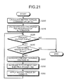
- step S230 If the present output Pt is smaller than the electric power Palt requested of the alternator (step S220-Y), whether or not the present output Pt is smaller than the stable maximum output Pmax is determined (step S230). If the present output Pt is smaller than the stable maximum output Pmax (step S230-Y) as a result of the determination, the present terminal voltage Vt is increased (step S240). Next, the present output Ptwp is increased to the stable limit electric power line SL (step S250). Then, by using the present output Pt, motor torque is applied (step S260).
- an increase in the present terminal voltage Vt may be a constant minute amount or may be changed according to a value obtained by subtracting the present output Pt from the smaller one of the electric power Palt requested of the alternator and the stable maximum output Pmax (MIN(Palt, Pmax)-Pt).
- the driving force controlling apparatus for a vehicle is useful to a driving force controlling apparatus for a vehicle including a motor for driving wheels other than driving wheels driven by an engine, with electric power from an electric generator, and is especially suitable for stably outputting the electric power from the electric generator.
Landscapes
- Engineering & Computer Science (AREA)
- Transportation (AREA)
- Mechanical Engineering (AREA)
- Chemical & Material Sciences (AREA)
- Combustion & Propulsion (AREA)
- Power Engineering (AREA)
- Automation & Control Theory (AREA)
- Hybrid Electric Vehicles (AREA)
- Electric Propulsion And Braking For Vehicles (AREA)
- Control Of Eletrric Generators (AREA)
Abstract
Description
- The present invention relates to a driving force controlling apparatus for a vehicle, and particularly to a driving force controlling apparatus for a vehicle including a motor for driving wheels other than driving wheels driven by an engine, with electric power from an electric generator.
- A driving force controlling apparatus for a vehicle including a motor for driving wheels other than driving wheels driven by an engine, with electric power from an electric generator is known conventionally. In an AC motor electric 4WD including an AC motor existing on a non-engine shaft and driven by electric power from an alternator, a request is made of the alternator to generate electric power necessary for the motor. For this purpose, there is a demand for a technique for causing the alternator to stably output the requested voltage to enable the motor to operate stably.
-
- Patent Document 1: Japanese Patent Application Laid-open No.
2006-206040 - Patent Document 2: Japanese Patent Application Laid-open No.
2006-306144 - Patent Document 3: Japanese Patent Application Laid-open No.
2006-296132 - Patent Document 4: Japanese Patent Application Laid-open No.
2006-315660 - As related art, there is a technique described in Japanese Patent Application Laid-open No.
2006-206040 - For example, if an upper limit voltage of the alternator is set at a predetermined value (42V in this example) as in a 42V alternator, for example, which is under consideration or employed in the motor vehicle industry, and if greater electric power than that the alternator can output stably is requested of the alternator, the alternator cannot stably output the electric power.
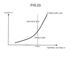
- As shown in
Fig. 23 , there is a limit to electric power that the alternator can output stably depending on voltage (the output is stable at greater voltage than voltage at which a maximum value Pmax of electric power P is output in a V-P characteristic). If the voltage is increased, the electric power that can be output stably can be increased as well. However, if the upper limit voltage Vmax is determined and requested electric power is excessively large, it becomes impossible to output it stably. In conventional art, there is no concept of the upper limit voltage. - It is an object of the present invention to provide a driving force controlling apparatus for a vehicle including a motor for driving wheels other than driving wheels driven by an engine, with electric power from an electric generator, the driving force controlling apparatus for a vehicle enabling the electric generator to stably output electric power.
- In order to solve the above mentioned problems and to achieve the object, a driving force controlling apparatus for a vehicle according to the present invention including an electric generator and a motor for driving a wheel other than a driving wheel, with electric power from the electric generator, the driving force controlling apparatus includes a requested electric power computing means that computes requested electric power required for operation of the motor, wherein target output of the electric generator is set based on the requested electric power and maximum output that the electric generator is capable of outputting stably.
- Further, in the driving force controlling apparatus for a vehicle, it is preferable that the stable maximum output of the electric generator is set based on an upper limit voltage of the electric generator.
- Further, in the driving force controlling apparatus for a vehicle, it is preferable that the stable maximum output of the electric generator is set based on a stable output line obtained from maximum outputs at different internal electromotive voltages of the electric generator.
- Further, in the driving force controlling apparatus for a vehicle, it is preferable that output of the electric generator is increased in such a manner as to move on an efficiency line set in advance in consideration of efficiency, when output of the electric generator is increased to the target output.
- Further, in the driving force controlling apparatus for a vehicle, it is preferable that the efficiency line is set based on at least one of efficiency of the electric generator, efficiency of an inverter between the electric generator and the motor, and efficiency of the motor.
- In the driving force controlling apparatus for a vehicle, it is preferable that output of the electric generator is increased in such a manner as to move on a stable output line obtained from maximum outputs at different internal electromotive voltages of the electric generator, when output of the electric generator is increased to the target output.
- With the driving force controlling apparatus for a vehicle according to the present invention, the driving force controlling apparatus for the vehicle including the motor for driving the wheels other than the driving wheels driven by the engine, with the electric power of the electric generator, can enable the electric generator to stably output electric power.
-
- [
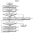
Fig. 1] Fig. 1 is a flowchart illustrating an operation of a first embodiment of a driving force controlling apparatus for a vehicle in the present invention. - [
Fig. 2] Fig. 2 is a schematic block diagram of the first embodiment of the driving force controlling apparatus for a vehicle in the present invention. - [
Fig. 3] Fig. 3 is a diagram for explaining stable maximum output of the first embodiment of the driving force controlling apparatus for a vehicle in the present invention. - [
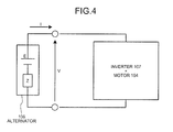
Fig. 4] Fig. 4 is a diagram for explaining a method of obtaining a V-P characteristic of an alternator in the first embodiment of the driving force controlling apparatus for a vehicle in the present invention. - [
Fig. 5] Fig. 5 is another diagram for explaining a method of obtaining the V-P characteristic of the alternator in the first embodiment of the driving force controlling apparatus for a vehicle in the present invention. - [
Fig. 6] Fig. 6 is a diagram for explaining forces acting when a deviation from a target output of the alternator occurs in the first embodiment of the driving force controlling apparatus for a vehicle in the present invention. - [
Fig. 7] Fig. 7 is a diagram for explaining a method of determining a stable limit electric power line in the first embodiment of the driving force controlling apparatus for a vehicle in the present invention. - [
Fig. 8] Fig. 8 is a diagram for explaining a difference in the stable limit electric power line due to a difference in rotational speed of the alternator in the first embodiment of the driving force controlling apparatus for a vehicle in the present invention. - [
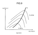
Fig. 9] Fig. 9 is another diagram for explaining a difference in the stable limit electric power line due to a difference in the rotational speed of the alternator in the first embodiment of the driving force controlling apparatus for a vehicle in the present invention. - [
Fig. 10] Fig. 10 is a diagram for explaining a maximum efficiency line in the first embodiment of the driving force controlling apparatus for a vehicle in the present invention. - [
Fig. 11] Fig. 11 is a diagram for explaining a region in which a target alternator output can be output in the first embodiment of the driving force controlling apparatus for a vehicle in the present invention. - [
Fig. 12] Fig. 12 is a diagram illustrating an efficiency characteristic of the alternator in the first embodiment of the driving force controlling apparatus for a vehicle in the present invention. - [
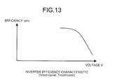
Fig. 13] Fig. 13 is a diagram illustrating an efficiency characteristic of an inverter in the first embodiment of the driving force controlling apparatus for a vehicle in the present invention. - [
Fig. 14] Fig. 14 is a diagram illustrating an efficiency characteristic of a motor in the first embodiment of the driving force controlling apparatus for a vehicle in the present invention. - [
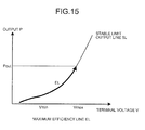
Fig. 15] Fig. 15 is another diagram for explaining the maximum efficiency line in the first embodiment of the driving force controlling apparatus for a vehicle in the present invention. - [
Fig. 16] Fig. 16 is a flowchart for explaining operation of a second embodiment of the driving force controlling apparatus for a vehicle in the present invention. - [
Fig. 17] Fig. 17 is a diagram for explaining operation when a target alternator output is equal to a stable maximum output in the second embodiment of the driving force controlling apparatus for a vehicle in the present invention. - [
Fig. 18] Fig. 18 is a diagram for explaining operation when the target alternator output is equal to electric power requested of the alternator in the second embodiment of the driving force controlling apparatus for a vehicle in the present invention. - [
Fig. 19] Fig. 19 is a flowchart illustrating operation of a third embodiment of the driving force controlling apparatus for a vehicle in the present invention. - [
Fig. 20] Fig. 20 is a diagram for explaining the operation of the third embodiment of the driving force controlling apparatus for a vehicle in the present invention. - [
Fig. 21] Fig. 21 is a flowchart illustrating operation of a fourth embodiment of the driving force controlling apparatus for a vehicle in the present invention. - [
Fig. 22] Fig. 22 is a diagram for explaining the operation of the fourth embodiment of the driving force controlling apparatus for a vehicle in the present invention. - [
Fig. 23] Fig. 23 is a diagram for explaining problems in conventional art. -
- 101
- engine
- 102
- shaft
- 103
- non-engine shaft
- 104
- AC motor
- 105
- belt
- 106
- alternator
- 107
- inverter
- 108
- tire
- 109
- means for changing a rotation ratio between the engine and tires
- EL
- maximum efficiency line
- Pm
- maximum value of output of the alternator
- Pmax
- stable maximum output
- Pout
- target alternator output
- SL
- Stable limit electric power line
- Vmax
- upper limit voltage
- An embodiment of a driving force controlling apparatus for a vehicle in the present invention will be described below in detail with reference to the drawings.
- With reference to the accompanying drawings, a first embodiment will be described.
-
Fig. 2 depicts a schematic constitution of the present embodiment. The schematic constitution includes anAC motor 104 for driving anon-engine shaft 103 other than ashaft 102 driven by anengine 101, analternator 106 connected to theengine 101 via abelt 105 to supply electric power to theAC motor 104, aninverter 107 for converting DC power generated by thealternator 106 into AC power, and means 109 for changing a rotation ratio between theengine 101 and tires 108 (irrespective of CVT, AT, or MMT). - The present embodiment relates to a method of controlling the
alternator 106 in an AC motor electric 4WD including theAC motor 104 existing on thenon-engine shaft 103 and driven with the electric power from thealternator 106. - There is a limit to the electric power that the
alternator 106 can output stably depending on voltage. Therefore, if an upper limit voltage is determined and requested electric power is excessively large, it is impossible to output it stably. Therefore, if the requested electric power is excessively large, thealternator 106 outputs the maximum electric power that it can output stably and motor torque is suppressed according to the electric power. - For example, if the upper limit voltage Vmax is set at a predetermined value (42V in the embodiment) as in a 42V alternator, which is under consideration or employed in the motor vehicle industry, and if greater electric power Palt than the limit Pmax that the
alternator 106 can output stably is requested of thealternator 106, thealternator 106 cannot stably output the electric power. It is an object of the embodiment to solve this problem. - With reference to
Fig. 1 , operation of the first embodiment will be described. - In step S100, a motor torque command value Tm representing torque that the
motor 104 should output is calculated by using a preset map or the like according to a traveling condition of a vehicle. - Next, in step S110, an electric power Palt requested of the alternator and representing electric power required to output the motor torque command value Tm is calculated. By using the motor torque command value Tm obtained in step S101, electric power used by the
motor 104, and efficiency maps of themotor 104, theinverter 107, and thealternator 106, the electric power requested of the alternator 106 (the electric power Palt requested of the alternator) is obtained. - Next, in step S120, whether or not the electric power Palt requested of the alternator is greater than a stable maximum output Pmax is determined. If the electric power Palt requested of the alternator is determined to be greater than the stable maximum output Pmax as a result of the determination, the control goes to step S130. If not, the control goes to step S140.
- The stable maximum output Pmax is retained as a map in advance. The stable maximum output Pmax is electric power at an intersection point of a stable limit electric power line SL and an upper limit voltage Vmax. The stable limit electric power line SL is obtained as follows.
- First, with reference to
Fig. 4 , a method of obtaining a V-P characteristic of thealternator 106 will be described. An output P of thealternator 106 will be obtained by means of the following expression (1).
- The internal electromotive voltage E is expressed by the following expression (2).

alternator 106. - First, stability will be described by using
Fig. 5 illustrating the V-P characteristic of thealternator 106. To output the electric power Palt requested of the alternator, thealternator 106 is operated at a point "a" or a point "b". - With reference to
Figs. 5 and6 , operation around the point a will be discussed. When a present power generation amount Pt of thealternator 106 becomes greater than the electric power Palt requested of thealternator 106 at the point a (point a1), electric power consumed by the motor is constant and therefore voltage of thealternator 106 rises (if the amount of power generation increases, the voltage rises to store surplus energy in a capacitor). As a result, the power generation amount Pt deviates from the point a. - On the other hand, when the present power generation amount Pt of the
alternator 106 becomes smaller than the electric power Palt requested of the alternator 106 (point a2), the voltage drops. As a result, the power generation amount Pt deviates from the point a. Therefore, with a minute change at the point a, it becomes impossible to output the electric power Palt requested of the alternator and the output becomes unstable. - Next, operation around the point b will be discussed. When a present power generation amount Pt of the
alternator 106 becomes greater than the electric power Palt requested of thealternator 106 at the point b (point b1), electric power consumed by themotor 104 is constant and therefore voltage of thealternator 106 rises. As a result, the power generation amount Pt approaches the point b. - On the other hand, when the present power generation amount Pt of the
alternator 106 becomes smaller than the electric power Palt requested of the alternator 106 (point b2), the voltage drops. As a result, the power generation amount Pt approaches the point b. Therefore, even if a minute change occurs around the point b, such a force as to bring the power generation amount Pt close to the point b acts and therefore it becomes possible to output the electric power Palt requested of the alternator and the output becomes stable. - For this reason, if the voltage is greater than voltage at which the output P of the
alternator 106 becomes the maximum value Pm, the output becomes stable. - Therefore, as shown in
Fig. 7 , the stable limit electric power line SL is obtained by changing a value of the internal electromotive force E and connecting the respective maximum values Pm of the output P of thealternator 106. If the voltage is greater than the stable limit electric power line SL, it is possible to stably output the requested electric power. - Although the line connecting the maximum values Pm of the output P of the
alternator 106 is defined as the stable electric power limit line, it is also possible to set a margin to make allowance. - Because the V-P characteristic shown in
Fig. 5 is given to every rotational speed Nalt of thealternator 106, the stable limit electric power line SL and the stable maximum output Pmax are also stored for each rotational speed Nalt of the alternator 106 (SeeFigs. 8 and9 . Nalt is low inFig. 8 and high inFig. 9 ). Therefore, the stable maximum output Pmax is stored in a map together with the rotational speed Nalt of thealternator 106. Accordingly, in step S120, the rotational speed Nalt of thealternator 106 is detected, and the Pmax is obtained from the map and compared with the Palt. - In step S130, a target alternator output Pout is set at the stable maximum output Pmax.
If the electric power Palt requested of the alternator is greater than the stable maximum output Pmax (step S120-Y), the electric power greater than the maximum electric power (stable maximum output Pmax) that thealternator 106 can output stably is requested. In this case, the target alternator output Pout is set at the stable maximum output Pmax so that thealternator 106 can output stably.
Following step S130, the control goes to step S150. - In step S140, the target alternator output Pout is set at the electric power Palt requested of the alternator. If the electric power Palt requested of the alternator is equal to or smaller than the stable maximum output Pmax (step S120-N), the electric power requested of the alternator 106 (the electric power Palt requested of the alternator) is in such a range that the
alternator 106 can output it stably. In this case, the target alternator output Pout is set at the electric power Palt requested of the alternator. Following step S140, the control goes to step S150. - In step S150, the present output Pt of the
alternator 106 and the target alternator output Pout are compared with each other to determine whether or not an end condition of this control is satisfied. Whether or not the present output Pt of thealternator 106 is smaller than the target alternator output Pout is determined. If the present output Pt of thealternator 106 is smaller than the target alternator output Pout as a result of the determination, the control goes to step S160. If not, this control ends. - In step S160, the present output Pt of the
alternator 106 is increased to move on a maximum efficiency line EL. - If the present output Pt of the
alternator 106 is smaller than the target alternator output Pout (step S150-Y), theinverter 107 requests thealternator 106 to increase the present output Pt of thealternator 106. At this time, the present output Pt of thealternator 106 is increased while controlling the excitation current to control the voltage so that the output moves on the maximum efficiency line EL obtained in advance. - A method of obtaining the maximum efficiency line EL (the most efficient course considering collectively from the
alternator 106 to the motor 104) when the rotational speed Nalt of thealternator 106, a rotational speed Nmot of themotor 104, torque Tmot of themotor 104 are fixed will be shown below. - Total efficiency η is obtained by multiplying efficiency ηalt of the
alternator 106 by efficiency ηinv of theinverter 107 and efficiency ηmot of the motor 104 (the following expression 3).
- When the target alternator output Pout is determined, the range in which the target alternator output Pout can be output stably is a portion shown with an arrow Y2 in
Figs. 10 and11 (the range in which the voltage is higher than the stable limit electric power line SL). - As shown in
Fig. 10 , the output electric power P of thealternator 106 is changed (P1, P2, P3 ...) and points Q (Q1, Q2, Q3 ...) with the maximum total efficiency η in the ranges Y2 in which the target alternator output Pout can be output stably for the respective values of the output electric power P (P1, P2, P3 ...) of thealternator 106 are connected to thereby obtain the maximum efficiency line EL. - Although the maximum efficiency line EL is obtained based on the total efficiency η that is the product of the efficiency ηalt of the
alternator 106, the efficiency ηinv of theinverter 107, and the efficiency ηmot of themotor 104 in the embodiment, the maximum efficiency line EL can be obtained based on at least one of the efficiency ηalt of thealternator 106, the efficiency ηinv of theinverter 107, and the efficiency ηmot of themotor 104 or based on the product of two of them. - The
alternator 106 in an example of the embodiment will be discussed.Fig. 12 shows a V-ηalt characteristic in the range Y2 in which thealternator 106 in the example can stably output the target alternator output Pout. In this range, the smaller the internal electromotive voltage E is, i.e., the lower the voltage V is, the higher the efficiency becomes. - The
inverter 107 in an example of the embodiment will be discussed.Fig. 13 shows a V-ηmot characteristic of theinverter 107 when the rotational speed and torque of themotor 104 are fixed. The lower the voltage is, the higher the efficiency of theinverter 107 becomes. - The
motor 104 in an example of the embodiment will be discussed.Fig. 14 shows a V-ηmot characteristic of themotor 104 when the rotational speed and torque of themotor 104 are fixed. The efficiency of themotor 104 hardly depends on the voltage. - Consequently, in the example of the embodiment, the lower the voltage is, the higher the total efficiency η becomes. Therefore, the maximum efficiency line EL coincides with the stable limit electric power line SL as shown in
Fig. 15 . - However,
different alternators 106,inverters 107, andmotors 104 have different efficiency characteristics. Thus, if the total efficiency has a monotone trend, it is necessary to form a map in advance where the efficiency ηalt of thealternator 106, the efficiency ηmot of themotor 104, and the torque Tmot of themotor 104 are arguments and voltages that provide the maximum efficiency are return values and obtain the maximum efficiency line EL based on the map. - Next, in step S170, the motor torque is applied by using the present output Pt of the
alternator 106. By using the present output Pt of thealternator 106, theAC motor 104 is driven and the torque is applied. Following step S170, the control returns to step S150. Thereafter, by repeating the operations in steps S150 to S170, motor torque according to the motor torque command value is output. - The present embodiment relates to the method of controlling the
alternator 106 in the AC motor electric 4WD including theAC motor 104 existing on the non-engine shaft and driven with the electric power from thealternator 106. There is the limit Pmax to the electric power that thealternator 106 can output stably depending on voltage. Therefore, if the upper limit voltage Vmax is determined and requested electric power Palt is excessively large, it is impossible to output it stably. Therefore, if the electric power Palt requested of the alternator is excessively large (step S120-Y), thealternator 106 outputs the maximum electric power Pmax (Pout=Pmax) that it can output stably and the motor torque is suppressed according to the electric power. In the present embodiment, the stability (step S120), the requested electric power (step S140), and the efficiency (step S160) are weighted in this order in controlling thealternator 106. In contrast to constant voltage control for increasing the output while keeping the terminal voltage V constant as control of the alternator in conventional art, the efficiency is taken into consideration in the present embodiment. - Next, with reference to
Figs. 16 to 18 , a second embodiment will be described.
In the second embodiment, portions common to the first embodiment will be provided with the same reference numerals and detailed description thereof will be omitted. - In the first embodiment, the present output Pt is increased to move on the maximum efficiency line EL (step S150 in
Fig. 1 ). In the second embodiment, on the other hand, control is carried out while keeping target voltage Vout constant in consideration of ease of control in increasing the present output Pt. - As shown in
Fig. 16 , in step S130 similar to that in the first embodiment, the target alternator output Pout is set at the stable maximum output Pmax. Then, in step S131, the target voltage Vout is set at the upper limit voltage Vmax (seeFig. 17 ). Following step S131, the control goes to step S150. - In step S140 similar to that in the first embodiment, the target alternator output Pout is set at the electric power Palt requested of the alternator. Then, in step S141, an intersection point A of a constant electric power line of the electric power Palt requested of the alternator and the stable limit electric power line SL is calculated as shown in
Fig. 18 . - Next, in step S142, the efficient voltage Ve in a range from voltage Va corresponding to the intersection point A obtained in step S141 to the upper limit voltage Vmax is calculated (see
Fig. 18 ). The most efficient voltage Ve is selected considering collectively from thealternator 106 to themotor 104. - Next, in step S143, the target voltage Vout is set at the voltage Ve (see
Fig. 18 ). Because the output is stable at any voltage between the voltage Va and the upper limit voltage Vmax, the target voltage Vout may be set at the voltage Va or at the voltage Vmax to omit calculation of efficiency. Following step S143, the control goes to step S150. - In step S150, similarly to the first embodiment, whether or not the present output Pt is smaller than the target alternator output Pout is determined. If the present output Pt is smaller than the target alternator output Pout as a result of determination, the control goes to step S161. If not, the control ends.
- In step S161, the present output Pt is increased while controlling an excitation current and keeping the target voltage Vout constant (see arrows Y3, Y4 in
Figs. 17, 18 ). - In step S170, similarly to the first embodiment, motor torque is generated by using the present output Pt. After step S170, steps from S150 to S170 are repeated until the result of the determination in step S150 becomes negative.
- Next, with reference to
Figs. 19 and20 , a third embodiment will be described.
In the third embodiment, portions common to the above embodiments will be provided with the same reference numerals and detailed description thereof will be omitted. - In the first embodiment, the target alternator output Pout is determined based on the result of comparison between the electric power Palt requested of the alternator and the stable maximum output Pmax (step S120, step S130, step S140). Instead, in the third embodiment, the target alternator output Pout can be determined by the upper limit voltage Vmax. This is because the upper limit voltage Vmax and the stable maximum output Pmax are in such a relationship that one of them determines the other based on the V-P characteristic.
- In step S111 in
Fig. 19 , an intersection point A of a constant electric power line of the electric power Palt requested of the alternator calculated in step S110 and the stable limit electric power line SL is obtained as shown inFig. 20 . - Next, in step S121, whether or not the upper limit voltage Vmax is higher than voltage Va at the point A obtained in step S111 is determined. If the upper limit voltage Vmax is determined to be higher than the voltage Va as a result of the determination, the target alternator output Pout is set at the stable maximum output Pmax in step S130. If not, the target alternator output Pout is set at the electric power Palt requested of the alternator in step S140.
- As described above, in step S121, comparison with the voltage instead of comparison with the electric power is possible.
- Next, with reference to
Figs. 21 and22 , a fourth embodiment will be described.
In the fourth embodiment, detailed description of portions common to the above embodiments will be omitted. - In the fourth embodiment, the method of increasing the present output Pt of the
alternator 106 is different. The present output Pt is increased along the maximum efficiency line EL in the first embodiment and the present output Pt is increased while keeping the voltage constant in the second embodiment. In the fourth embodiment, the present output Pt is increased to the stable maximum output Pmax along the stable limit electric power line SL (see steps S230 to S250 inFig. 21 ,Fig. 22 ). - If the present output Pt is smaller than the electric power Palt requested of the alternator (step S220-Y), whether or not the present output Pt is smaller than the stable maximum output Pmax is determined (step S230). If the present output Pt is smaller than the stable maximum output Pmax (step S230-Y) as a result of the determination, the present terminal voltage Vt is increased (step S240). Next, the present output Ptwp is increased to the stable limit electric power line SL (step S250). Then, by using the present output Pt, motor torque is applied (step S260).
- In step S240, an increase in the present terminal voltage Vt may be a constant minute amount or may be changed according to a value obtained by subtracting the present output Pt from the smaller one of the electric power Palt requested of the alternator and the stable maximum output Pmax (MIN(Palt, Pmax)-Pt).
- As described above, the driving force controlling apparatus for a vehicle according to the present invention is useful to a driving force controlling apparatus for a vehicle including a motor for driving wheels other than driving wheels driven by an engine, with electric power from an electric generator, and is especially suitable for stably outputting the electric power from the electric generator.
Claims (10)
- A driving force controlling apparatus for a vehicle including an electric generator and a motor for driving a wheel other than a driving wheel, with electric power from the electric generator, the driving force controlling apparatus comprising:a requested electric power computing means that computes requested electric power required for operation of the motor, whereintarget output of the electric generator is set based on the requested electric power and maximum output that the electric generator is capable of outputting stably.
- A driving force controlling apparatus for a vehicle according to claim 1, wherein the stable maximum output of the electric generator is set based on an upper limit voltage of the electric generator.
- A driving force controlling apparatus for a vehicle according to claim 2, wherein the stable maximum output of the electric generator is set based on a stable output line obtained from maximum outputs at different internal electromotive voltages of the electric generator.
- A driving force controlling apparatus for a vehicle according to claim 3, wherein output of the electric generator is increased in such a manner as to move on an efficiency line set in advance in consideration of efficiency, when output of the electric generator is increased to the target output.
- A driving force controlling apparatus for a vehicle according to claim 1, wherein the stable maximum output of the electric generator is set based on a stable output line obtained from maximum outputs at different internal electromotive voltages of the electric generator.
- A driving force controlling apparatus for a vehicle according to claim 5, wherein output of the electric generator is increased in such a manner as to move on an efficiency line set in advance in consideration of efficiency, when output of the electric generator is increased to the target output.
- A driving force controlling apparatus for a vehicle according to claim 1, wherein output of the electric generator is increased in such a manner as to move on an efficiency line set in advance in consideration of efficiency, when output of the electric generator is increased to the target output.
- A driving force controlling apparatus for a vehicle according to claim 2, wherein output of the electric generator is increased in such a manner as to move on an efficiency line set in advance in consideration of efficiency, when output of the electric generator is increased to the target output.
- A driving force controlling apparatus for a vehicle according to any one of claims 4, 6 to 8, wherein the efficiency line is set based on at least one of efficiency of the electric generator, efficiency of an inverter between the electric generator and the motor, and efficiency of the motor.
- A driving force controlling apparatus for a vehicle according to any one of claims 1 to 3 and 5, wherein output of the electric generator is increased in such a manner as to move on a stable output line obtained from maximum outputs at different internal electromotive voltages of the electric generator, when output of the electric generator is increased to the target output.
Applications Claiming Priority (2)
| Application Number | Priority Date | Filing Date | Title |
|---|---|---|---|
| JP2007123730A JP4456134B2 (en) | 2007-05-08 | 2007-05-08 | Vehicle driving force control device |
| PCT/JP2008/057955 WO2008139885A1 (en) | 2007-05-08 | 2008-04-24 | Driving force control device for vehicle |
Publications (3)
| Publication Number | Publication Date |
|---|---|
| EP2154042A1 true EP2154042A1 (en) | 2010-02-17 |
| EP2154042A4 EP2154042A4 (en) | 2016-07-27 |
| EP2154042B1 EP2154042B1 (en) | 2018-11-14 |
Family
ID=40002101
Family Applications (1)
| Application Number | Title | Priority Date | Filing Date |
|---|---|---|---|
| EP08740832.4A Active EP2154042B1 (en) | 2007-05-08 | 2008-04-24 | Driving force control device for vehicle |
Country Status (5)
| Country | Link |
|---|---|
| US (1) | US8463471B2 (en) |
| EP (1) | EP2154042B1 (en) |
| JP (1) | JP4456134B2 (en) |
| CN (1) | CN101678824B (en) |
| WO (1) | WO2008139885A1 (en) |
Families Citing this family (4)
| Publication number | Priority date | Publication date | Assignee | Title |
|---|---|---|---|---|
| JP5709722B2 (en) * | 2011-10-24 | 2015-04-30 | 三菱電機株式会社 | Vehicle power supply |
| JP2014162293A (en) * | 2013-02-22 | 2014-09-08 | Denso Corp | Driving force control device of vehicle |
| EP2778252A3 (en) * | 2013-03-15 | 2014-12-10 | Apple Inc. | Layered Coatings For Sapphire Structure |
| CN103935354B (en) * | 2014-04-11 | 2016-05-25 | 武汉理工大学 | Driving force coordinated control system and the control method of multiaxis independence Electric Motor Wheel vehicle |
Family Cites Families (15)
| Publication number | Priority date | Publication date | Assignee | Title |
|---|---|---|---|---|
| JP2517901B2 (en) | 1985-12-12 | 1996-07-24 | 株式会社明電舍 | Excitation control device |
| JPH0636680B2 (en) | 1987-08-14 | 1994-05-11 | 株式会社日立製作所 | Variable speed generator |
| JP3702749B2 (en) * | 2000-05-24 | 2005-10-05 | トヨタ自動車株式会社 | Hybrid vehicle and control method thereof |
| JP4029592B2 (en) * | 2001-09-05 | 2008-01-09 | 株式会社日立製作所 | Auxiliary drive device and automobile equipped with the same |
| JP3731594B2 (en) * | 2003-10-08 | 2006-01-05 | 日産自動車株式会社 | VEHICLE POWER GENERATION CONTROL DEVICE AND VEHICLE DRIVE CONTROL DEVICE HAVING THE SAME |
| JP3991983B2 (en) * | 2003-12-19 | 2007-10-17 | 日産自動車株式会社 | Vehicle drive control device |
| US7151987B2 (en) * | 2004-02-17 | 2006-12-19 | Ford Global Technologies, Llc | System for reducing powertrain reaction torque |
| DE102004055128A1 (en) * | 2004-11-16 | 2006-06-01 | Volkswagen Ag | Method for controlling an operation of a hybrid motor vehicle and hybrid vehicle |
| US7441616B2 (en) * | 2004-12-27 | 2008-10-28 | Nissan Motor Co., Ltd. | Generated power control system |
| JP2006187090A (en) * | 2004-12-27 | 2006-07-13 | Nissan Motor Co Ltd | Generator power control device |
| JP2006206040A (en) | 2004-12-28 | 2006-08-10 | Nissan Motor Co Ltd | Vehicle drive control device |
| JP4876429B2 (en) | 2005-04-13 | 2012-02-15 | 日産自動車株式会社 | Vehicle drive control device |
| JP2006315660A (en) * | 2005-04-13 | 2006-11-24 | Nissan Motor Co Ltd | Vehicle drive control device |
| JP2006306144A (en) | 2005-04-26 | 2006-11-09 | Nissan Motor Co Ltd | Vehicle drive control device |
| JP4501812B2 (en) * | 2005-08-09 | 2010-07-14 | トヨタ自動車株式会社 | Maximum output setting device, drive device including the same, power output device including the same, automobile equipped with the same, maximum output setting method |
-
2007
- 2007-05-08 JP JP2007123730A patent/JP4456134B2/en not_active Expired - Fee Related
-
2008
- 2008-04-24 US US12/599,167 patent/US8463471B2/en not_active Expired - Fee Related
- 2008-04-24 EP EP08740832.4A patent/EP2154042B1/en active Active
- 2008-04-24 WO PCT/JP2008/057955 patent/WO2008139885A1/en not_active Ceased
- 2008-04-24 CN CN200880015328.3A patent/CN101678824B/en not_active Expired - Fee Related
Also Published As
| Publication number | Publication date |
|---|---|
| CN101678824B (en) | 2014-08-27 |
| CN101678824A (en) | 2010-03-24 |
| EP2154042A4 (en) | 2016-07-27 |
| JP2008279810A (en) | 2008-11-20 |
| US8463471B2 (en) | 2013-06-11 |
| JP4456134B2 (en) | 2010-04-28 |
| US20100324764A1 (en) | 2010-12-23 |
| EP2154042B1 (en) | 2018-11-14 |
| WO2008139885A1 (en) | 2008-11-20 |
Similar Documents
| Publication | Publication Date | Title |
|---|---|---|
| US7982435B2 (en) | Battery charging and discharging control apparatus | |
| CN101384461B (en) | Controller and control method for charging/discharging secondary battery | |
| Guzzella et al. | Vehicle propulsion systems: introduction to modeling and optimization | |
| JP4930482B2 (en) | Battery charge / discharge control device | |
| US10569660B2 (en) | Systems and methods for battery state-of-health monitoring | |
| US8907612B2 (en) | Inverter for driving an electric motor comprising an integrated regulator | |
| EP2528189B1 (en) | Battery charging control system | |
| US20160006275A1 (en) | System and method for battery open circuit voltage estimation | |
| CN101262143A (en) | Vehicle power supply equipment | |
| EP2154042B1 (en) | Driving force control device for vehicle | |
| EP3706310A1 (en) | Electric motor control device | |
| EP2677658A1 (en) | Regeneration control system for vehicle | |
| CN108155787B (en) | Drive device | |
| EP1241042B1 (en) | Motor-generator control in a hybrid vehicle | |
| US20120310567A1 (en) | Determining the internal resistance of a battery cell of a traction battery that is connected to a controllable motor/generator | |
| CN103283103B (en) | Power-supply system, carry its vehicle and the control method of electrical storage device | |
| US8922036B2 (en) | Vehicular power generation system and power generation control method for the same | |
| Gao et al. | Flywheel electric motor/generator characterization for hybrid vehicles | |
| CN114646874B (en) | Method for classifying the performance of an electric traction machine as a permanent magnet synchronous motor | |
| CN114206658B (en) | Method for managing the torque to be provided by an electric motor | |
| Al-Adsani et al. | Efficiency and Operational Envelop of a Hybrid PM Machine System for HEVs | |
| KR101405745B1 (en) | Engine Torque Control Method in Vehicle | |
| Nguyen et al. | Impact of the intermittent control on the torque pulsation of a switched reluctance machine | |
| EP4016833B1 (en) | A method for adapting the control parameters of an electric traction machine being a permanent magnet synchronous motor | |
| JP7028036B2 (en) | Electric vehicle |
Legal Events
| Date | Code | Title | Description |
|---|---|---|---|
| PUAI | Public reference made under article 153(3) epc to a published international application that has entered the european phase |
Free format text: ORIGINAL CODE: 0009012 |
|
| 17P | Request for examination filed |
Effective date: 20091127 |
|
| AK | Designated contracting states |
Kind code of ref document: A1 Designated state(s): AT BE BG CH CY CZ DE DK EE ES FI FR GB GR HR HU IE IS IT LI LT LU LV MC MT NL NO PL PT RO SE SI SK TR |
|
| AX | Request for extension of the european patent |
Extension state: AL BA MK RS |
|
| DAX | Request for extension of the european patent (deleted) | ||
| RAP1 | Party data changed (applicant data changed or rights of an application transferred) |
Owner name: DENSO CORPORATION Owner name: TOYOTA JIDOSHA KABUSHIKI KAISHA |
|
| RA4 | Supplementary search report drawn up and despatched (corrected) |
Effective date: 20160627 |
|
| RIC1 | Information provided on ipc code assigned before grant |
Ipc: B60W 10/08 20060101AFI20160621BHEP Ipc: H02P 9/04 20060101ALI20160621BHEP Ipc: B60L 11/14 20060101ALI20160621BHEP Ipc: B60K 6/34 20071001ALI20160621BHEP Ipc: B60W 20/00 20160101ALI20160621BHEP Ipc: B60K 6/44 20071001ALI20160621BHEP Ipc: B60K 6/52 20071001ALI20160621BHEP |
|
| REG | Reference to a national code |
Ref country code: DE Ref legal event code: R079 Ref document number: 602008057906 Country of ref document: DE Free format text: PREVIOUS MAIN CLASS: B60W0010080000 Ipc: B60L0015200000 |
|
| RIC1 | Information provided on ipc code assigned before grant |
Ipc: B60W 10/08 20060101ALI20180502BHEP Ipc: B60W 20/10 20160101ALI20180502BHEP Ipc: B60W 20/00 20160101ALI20180502BHEP Ipc: B60L 15/20 20060101AFI20180502BHEP Ipc: B60K 6/52 20071001ALI20180502BHEP Ipc: B60L 11/14 20060101ALI20180502BHEP Ipc: B60K 6/44 20071001ALI20180502BHEP |
|
| GRAP | Despatch of communication of intention to grant a patent |
Free format text: ORIGINAL CODE: EPIDOSNIGR1 |
|
| STAA | Information on the status of an ep patent application or granted ep patent |
Free format text: STATUS: GRANT OF PATENT IS INTENDED |
|
| INTG | Intention to grant announced |
Effective date: 20180608 |
|
| GRAS | Grant fee paid |
Free format text: ORIGINAL CODE: EPIDOSNIGR3 |
|
| GRAA | (expected) grant |
Free format text: ORIGINAL CODE: 0009210 |
|
| STAA | Information on the status of an ep patent application or granted ep patent |
Free format text: STATUS: THE PATENT HAS BEEN GRANTED |
|
| AK | Designated contracting states |
Kind code of ref document: B1 Designated state(s): AT BE BG CH CY CZ DE DK EE ES FI FR GB GR HR HU IE IS IT LI LT LU LV MC MT NL NO PL PT RO SE SI SK TR |
|
| REG | Reference to a national code |
Ref country code: GB Ref legal event code: FG4D |
|
| REG | Reference to a national code |
Ref country code: CH Ref legal event code: EP Ref country code: AT Ref legal event code: REF Ref document number: 1064394 Country of ref document: AT Kind code of ref document: T Effective date: 20181115 |
|
| REG | Reference to a national code |
Ref country code: DE Ref legal event code: R096 Ref document number: 602008057906 Country of ref document: DE |
|
| REG | Reference to a national code |
Ref country code: IE Ref legal event code: FG4D |
|
| REG | Reference to a national code |
Ref country code: CH Ref legal event code: PK Free format text: BERICHTIGUNGEN |
|
| RIC2 | Information provided on ipc code assigned after grant |
Ipc: B60W 20/00 20160101ALI20180502BHEP Ipc: B60L 11/14 20060101ALI20180502BHEP Ipc: B60W 20/10 20160101ALI20180502BHEP Ipc: B60W 10/08 20060101ALI20180502BHEP Ipc: B60L 15/20 20060101AFI20180502BHEP Ipc: B60K 6/44 20071001ALI20180502BHEP Ipc: B60K 6/52 20071001ALI20180502BHEP |
|
| REG | Reference to a national code |
Ref country code: NL Ref legal event code: MP Effective date: 20181114 |
|
| REG | Reference to a national code |
Ref country code: LT Ref legal event code: MG4D |
|
| REG | Reference to a national code |
Ref country code: AT Ref legal event code: MK05 Ref document number: 1064394 Country of ref document: AT Kind code of ref document: T Effective date: 20181114 |
|
| PG25 | Lapsed in a contracting state [announced via postgrant information from national office to epo] |
Ref country code: IS Free format text: LAPSE BECAUSE OF FAILURE TO SUBMIT A TRANSLATION OF THE DESCRIPTION OR TO PAY THE FEE WITHIN THE PRESCRIBED TIME-LIMIT Effective date: 20190314 Ref country code: FI Free format text: LAPSE BECAUSE OF FAILURE TO SUBMIT A TRANSLATION OF THE DESCRIPTION OR TO PAY THE FEE WITHIN THE PRESCRIBED TIME-LIMIT Effective date: 20181114 Ref country code: LT Free format text: LAPSE BECAUSE OF FAILURE TO SUBMIT A TRANSLATION OF THE DESCRIPTION OR TO PAY THE FEE WITHIN THE PRESCRIBED TIME-LIMIT Effective date: 20181114 Ref country code: BG Free format text: LAPSE BECAUSE OF FAILURE TO SUBMIT A TRANSLATION OF THE DESCRIPTION OR TO PAY THE FEE WITHIN THE PRESCRIBED TIME-LIMIT Effective date: 20190214 Ref country code: HR Free format text: LAPSE BECAUSE OF FAILURE TO SUBMIT A TRANSLATION OF THE DESCRIPTION OR TO PAY THE FEE WITHIN THE PRESCRIBED TIME-LIMIT Effective date: 20181114 Ref country code: LV Free format text: LAPSE BECAUSE OF FAILURE TO SUBMIT A TRANSLATION OF THE DESCRIPTION OR TO PAY THE FEE WITHIN THE PRESCRIBED TIME-LIMIT Effective date: 20181114 Ref country code: ES Free format text: LAPSE BECAUSE OF FAILURE TO SUBMIT A TRANSLATION OF THE DESCRIPTION OR TO PAY THE FEE WITHIN THE PRESCRIBED TIME-LIMIT Effective date: 20181114 Ref country code: NO Free format text: LAPSE BECAUSE OF FAILURE TO SUBMIT A TRANSLATION OF THE DESCRIPTION OR TO PAY THE FEE WITHIN THE PRESCRIBED TIME-LIMIT Effective date: 20190214 Ref country code: AT Free format text: LAPSE BECAUSE OF FAILURE TO SUBMIT A TRANSLATION OF THE DESCRIPTION OR TO PAY THE FEE WITHIN THE PRESCRIBED TIME-LIMIT Effective date: 20181114 |
|
| PG25 | Lapsed in a contracting state [announced via postgrant information from national office to epo] |
Ref country code: PT Free format text: LAPSE BECAUSE OF FAILURE TO SUBMIT A TRANSLATION OF THE DESCRIPTION OR TO PAY THE FEE WITHIN THE PRESCRIBED TIME-LIMIT Effective date: 20190314 Ref country code: GR Free format text: LAPSE BECAUSE OF FAILURE TO SUBMIT A TRANSLATION OF THE DESCRIPTION OR TO PAY THE FEE WITHIN THE PRESCRIBED TIME-LIMIT Effective date: 20190215 Ref country code: NL Free format text: LAPSE BECAUSE OF FAILURE TO SUBMIT A TRANSLATION OF THE DESCRIPTION OR TO PAY THE FEE WITHIN THE PRESCRIBED TIME-LIMIT Effective date: 20181114 Ref country code: SE Free format text: LAPSE BECAUSE OF FAILURE TO SUBMIT A TRANSLATION OF THE DESCRIPTION OR TO PAY THE FEE WITHIN THE PRESCRIBED TIME-LIMIT Effective date: 20181114 |
|
| PG25 | Lapsed in a contracting state [announced via postgrant information from national office to epo] |
Ref country code: IT Free format text: LAPSE BECAUSE OF FAILURE TO SUBMIT A TRANSLATION OF THE DESCRIPTION OR TO PAY THE FEE WITHIN THE PRESCRIBED TIME-LIMIT Effective date: 20181114 Ref country code: CZ Free format text: LAPSE BECAUSE OF FAILURE TO SUBMIT A TRANSLATION OF THE DESCRIPTION OR TO PAY THE FEE WITHIN THE PRESCRIBED TIME-LIMIT Effective date: 20181114 Ref country code: DK Free format text: LAPSE BECAUSE OF FAILURE TO SUBMIT A TRANSLATION OF THE DESCRIPTION OR TO PAY THE FEE WITHIN THE PRESCRIBED TIME-LIMIT Effective date: 20181114 Ref country code: PL Free format text: LAPSE BECAUSE OF FAILURE TO SUBMIT A TRANSLATION OF THE DESCRIPTION OR TO PAY THE FEE WITHIN THE PRESCRIBED TIME-LIMIT Effective date: 20181114 |
|
| REG | Reference to a national code |
Ref country code: DE Ref legal event code: R097 Ref document number: 602008057906 Country of ref document: DE |
|
| PG25 | Lapsed in a contracting state [announced via postgrant information from national office to epo] |
Ref country code: SK Free format text: LAPSE BECAUSE OF FAILURE TO SUBMIT A TRANSLATION OF THE DESCRIPTION OR TO PAY THE FEE WITHIN THE PRESCRIBED TIME-LIMIT Effective date: 20181114 Ref country code: RO Free format text: LAPSE BECAUSE OF FAILURE TO SUBMIT A TRANSLATION OF THE DESCRIPTION OR TO PAY THE FEE WITHIN THE PRESCRIBED TIME-LIMIT Effective date: 20181114 Ref country code: EE Free format text: LAPSE BECAUSE OF FAILURE TO SUBMIT A TRANSLATION OF THE DESCRIPTION OR TO PAY THE FEE WITHIN THE PRESCRIBED TIME-LIMIT Effective date: 20181114 |
|
| PLBE | No opposition filed within time limit |
Free format text: ORIGINAL CODE: 0009261 |
|
| STAA | Information on the status of an ep patent application or granted ep patent |
Free format text: STATUS: NO OPPOSITION FILED WITHIN TIME LIMIT |
|
| 26N | No opposition filed |
Effective date: 20190815 |
|
| PG25 | Lapsed in a contracting state [announced via postgrant information from national office to epo] |
Ref country code: SI Free format text: LAPSE BECAUSE OF FAILURE TO SUBMIT A TRANSLATION OF THE DESCRIPTION OR TO PAY THE FEE WITHIN THE PRESCRIBED TIME-LIMIT Effective date: 20181114 |
|
| REG | Reference to a national code |
Ref country code: CH Ref legal event code: PL |
|
| REG | Reference to a national code |
Ref country code: DE Ref legal event code: R084 Ref document number: 602008057906 Country of ref document: DE |
|
| REG | Reference to a national code |
Ref country code: BE Ref legal event code: MM Effective date: 20190430 |
|
| GBPC | Gb: european patent ceased through non-payment of renewal fee |
Effective date: 20190424 |
|
| PG25 | Lapsed in a contracting state [announced via postgrant information from national office to epo] |
Ref country code: MC Free format text: LAPSE BECAUSE OF FAILURE TO SUBMIT A TRANSLATION OF THE DESCRIPTION OR TO PAY THE FEE WITHIN THE PRESCRIBED TIME-LIMIT Effective date: 20181114 Ref country code: LU Free format text: LAPSE BECAUSE OF NON-PAYMENT OF DUE FEES Effective date: 20190424 |
|
| PG25 | Lapsed in a contracting state [announced via postgrant information from national office to epo] |
Ref country code: LI Free format text: LAPSE BECAUSE OF NON-PAYMENT OF DUE FEES Effective date: 20190430 Ref country code: CH Free format text: LAPSE BECAUSE OF NON-PAYMENT OF DUE FEES Effective date: 20190430 Ref country code: GB Free format text: LAPSE BECAUSE OF NON-PAYMENT OF DUE FEES Effective date: 20190424 |
|
| PG25 | Lapsed in a contracting state [announced via postgrant information from national office to epo] |
Ref country code: FR Free format text: LAPSE BECAUSE OF NON-PAYMENT OF DUE FEES Effective date: 20190430 Ref country code: BE Free format text: LAPSE BECAUSE OF NON-PAYMENT OF DUE FEES Effective date: 20190430 |
|
| PG25 | Lapsed in a contracting state [announced via postgrant information from national office to epo] |
Ref country code: TR Free format text: LAPSE BECAUSE OF FAILURE TO SUBMIT A TRANSLATION OF THE DESCRIPTION OR TO PAY THE FEE WITHIN THE PRESCRIBED TIME-LIMIT Effective date: 20181114 |
|
| PG25 | Lapsed in a contracting state [announced via postgrant information from national office to epo] |
Ref country code: IE Free format text: LAPSE BECAUSE OF NON-PAYMENT OF DUE FEES Effective date: 20190424 |
|
| PG25 | Lapsed in a contracting state [announced via postgrant information from national office to epo] |
Ref country code: CY Free format text: LAPSE BECAUSE OF FAILURE TO SUBMIT A TRANSLATION OF THE DESCRIPTION OR TO PAY THE FEE WITHIN THE PRESCRIBED TIME-LIMIT Effective date: 20181114 |
|
| PG25 | Lapsed in a contracting state [announced via postgrant information from national office to epo] |
Ref country code: HU Free format text: LAPSE BECAUSE OF FAILURE TO SUBMIT A TRANSLATION OF THE DESCRIPTION OR TO PAY THE FEE WITHIN THE PRESCRIBED TIME-LIMIT; INVALID AB INITIO Effective date: 20080424 Ref country code: MT Free format text: LAPSE BECAUSE OF FAILURE TO SUBMIT A TRANSLATION OF THE DESCRIPTION OR TO PAY THE FEE WITHIN THE PRESCRIBED TIME-LIMIT Effective date: 20181114 |
|
| PGFP | Annual fee paid to national office [announced via postgrant information from national office to epo] |
Ref country code: DE Payment date: 20250422 Year of fee payment: 18 |