EP2153894A1 - Catalyst for the reduction of nitrogen oxides in exhaust gas - Google Patents
Catalyst for the reduction of nitrogen oxides in exhaust gas Download PDFInfo
- Publication number
- EP2153894A1 EP2153894A1 EP08014006A EP08014006A EP2153894A1 EP 2153894 A1 EP2153894 A1 EP 2153894A1 EP 08014006 A EP08014006 A EP 08014006A EP 08014006 A EP08014006 A EP 08014006A EP 2153894 A1 EP2153894 A1 EP 2153894A1
- Authority
- EP
- European Patent Office
- Prior art keywords
- catalyst
- temperature
- process according
- catalyst according
- nitrogen oxides
- Prior art date
- Legal status (The legal status is an assumption and is not a legal conclusion. Google has not performed a legal analysis and makes no representation as to the accuracy of the status listed.)
- Withdrawn
Links
- MWUXSHHQAYIFBG-UHFFFAOYSA-N nitrogen oxide Inorganic materials O=[N] MWUXSHHQAYIFBG-UHFFFAOYSA-N 0.000 title claims abstract description 131
- 239000003054 catalyst Substances 0.000 title claims abstract description 96
- 239000007789 gas Substances 0.000 title claims abstract description 20
- 230000009467 reduction Effects 0.000 title claims abstract description 17
- BASFCYQUMIYNBI-UHFFFAOYSA-N platinum Chemical group [Pt] BASFCYQUMIYNBI-UHFFFAOYSA-N 0.000 claims abstract description 24
- IJGRMHOSHXDMSA-UHFFFAOYSA-N Atomic nitrogen Chemical compound N#N IJGRMHOSHXDMSA-UHFFFAOYSA-N 0.000 claims abstract description 12
- ZLMJMSJWJFRBEC-UHFFFAOYSA-N Potassium Chemical compound [K] ZLMJMSJWJFRBEC-UHFFFAOYSA-N 0.000 claims abstract description 11
- 229910052751 metal Inorganic materials 0.000 claims abstract description 11
- 239000002184 metal Substances 0.000 claims abstract description 11
- 229910052700 potassium Inorganic materials 0.000 claims abstract description 11
- 239000011591 potassium Substances 0.000 claims abstract description 11
- 239000011232 storage material Substances 0.000 claims abstract description 11
- 229910052757 nitrogen Inorganic materials 0.000 claims abstract description 6
- 239000004071 soot Substances 0.000 claims description 24
- 229910001701 hydrotalcite Inorganic materials 0.000 claims description 18
- 229960001545 hydrotalcite Drugs 0.000 claims description 18
- 238000000034 method Methods 0.000 claims description 17
- 230000008569 process Effects 0.000 claims description 14
- 239000000463 material Substances 0.000 claims description 13
- 239000000243 solution Substances 0.000 claims description 13
- 238000007254 oxidation reaction Methods 0.000 claims description 11
- 230000003647 oxidation Effects 0.000 claims description 10
- 229910020038 Mg6Al2 Inorganic materials 0.000 claims description 8
- 229910021502 aluminium hydroxide Inorganic materials 0.000 claims description 7
- WNROFYMDJYEPJX-UHFFFAOYSA-K aluminium hydroxide Chemical compound [OH-].[OH-].[OH-].[Al+3] WNROFYMDJYEPJX-UHFFFAOYSA-K 0.000 claims description 7
- 229910001679 gibbsite Inorganic materials 0.000 claims description 7
- 229910052697 platinum Inorganic materials 0.000 claims description 7
- 238000005470 impregnation Methods 0.000 claims description 6
- 238000003756 stirring Methods 0.000 claims description 6
- 239000001095 magnesium carbonate Substances 0.000 claims description 5
- ZLNQQNXFFQJAID-UHFFFAOYSA-L magnesium carbonate Chemical compound [Mg+2].[O-]C([O-])=O ZLNQQNXFFQJAID-UHFFFAOYSA-L 0.000 claims description 5
- 229910000021 magnesium carbonate Inorganic materials 0.000 claims description 5
- 238000002360 preparation method Methods 0.000 claims description 5
- 239000000725 suspension Substances 0.000 claims description 5
- -1 hydrotalcite compound Chemical class 0.000 claims description 4
- 239000007864 aqueous solution Substances 0.000 claims description 3
- 238000002955 isolation Methods 0.000 claims description 3
- 239000007787 solid Substances 0.000 claims description 3
- 238000001914 filtration Methods 0.000 claims description 2
- 150000003839 salts Chemical class 0.000 claims description 2
- 239000007858 starting material Substances 0.000 claims description 2
- 235000019391 nitrogen oxide Nutrition 0.000 claims 2
- 238000004519 manufacturing process Methods 0.000 abstract description 3
- 238000006243 chemical reaction Methods 0.000 description 51
- 238000012360 testing method Methods 0.000 description 35
- CURLTUGMZLYLDI-UHFFFAOYSA-N Carbon dioxide Chemical compound O=C=O CURLTUGMZLYLDI-UHFFFAOYSA-N 0.000 description 31
- 229910002092 carbon dioxide Inorganic materials 0.000 description 26
- 238000003860 storage Methods 0.000 description 20
- 239000011777 magnesium Substances 0.000 description 17
- GDVKFRBCXAPAQJ-UHFFFAOYSA-A dialuminum;hexamagnesium;carbonate;hexadecahydroxide Chemical compound [OH-].[OH-].[OH-].[OH-].[OH-].[OH-].[OH-].[OH-].[OH-].[OH-].[OH-].[OH-].[OH-].[OH-].[OH-].[OH-].[Mg+2].[Mg+2].[Mg+2].[Mg+2].[Mg+2].[Mg+2].[Al+3].[Al+3].[O-]C([O-])=O GDVKFRBCXAPAQJ-UHFFFAOYSA-A 0.000 description 16
- XLYOFNOQVPJJNP-UHFFFAOYSA-N water Substances O XLYOFNOQVPJJNP-UHFFFAOYSA-N 0.000 description 14
- 239000000203 mixture Substances 0.000 description 13
- 229910001868 water Inorganic materials 0.000 description 13
- 230000000694 effects Effects 0.000 description 12
- 239000000446 fuel Substances 0.000 description 8
- 229910000000 metal hydroxide Inorganic materials 0.000 description 8
- 150000004692 metal hydroxides Chemical class 0.000 description 8
- JCXJVPUVTGWSNB-UHFFFAOYSA-N nitrogen dioxide Inorganic materials O=[N]=O JCXJVPUVTGWSNB-UHFFFAOYSA-N 0.000 description 8
- 239000010453 quartz Substances 0.000 description 8
- VYPSYNLAJGMNEJ-UHFFFAOYSA-N silicon dioxide Inorganic materials O=[Si]=O VYPSYNLAJGMNEJ-UHFFFAOYSA-N 0.000 description 8
- 150000001768 cations Chemical class 0.000 description 7
- 229930195733 hydrocarbon Natural products 0.000 description 7
- 150000002430 hydrocarbons Chemical class 0.000 description 7
- 239000010410 layer Substances 0.000 description 7
- 239000002245 particle Substances 0.000 description 7
- 230000003197 catalytic effect Effects 0.000 description 6
- 239000002734 clay mineral Substances 0.000 description 6
- UGFAIRIUMAVXCW-UHFFFAOYSA-N Carbon monoxide Chemical compound [O+]#[C-] UGFAIRIUMAVXCW-UHFFFAOYSA-N 0.000 description 5
- 229910002091 carbon monoxide Inorganic materials 0.000 description 5
- 230000000052 comparative effect Effects 0.000 description 5
- 150000001875 compounds Chemical class 0.000 description 5
- MCMNRKCIXSYSNV-UHFFFAOYSA-N Zirconium dioxide Chemical compound O=[Zr]=O MCMNRKCIXSYSNV-UHFFFAOYSA-N 0.000 description 4
- 150000001450 anions Chemical class 0.000 description 4
- QVGXLLKOCUKJST-UHFFFAOYSA-N atomic oxygen Chemical compound [O] QVGXLLKOCUKJST-UHFFFAOYSA-N 0.000 description 4
- 125000004122 cyclic group Chemical group 0.000 description 4
- 150000004679 hydroxides Chemical class 0.000 description 4
- 150000002823 nitrates Chemical class 0.000 description 4
- 229910000510 noble metal Inorganic materials 0.000 description 4
- 229910052760 oxygen Inorganic materials 0.000 description 4
- 239000001301 oxygen Substances 0.000 description 4
- 239000002243 precursor Substances 0.000 description 4
- 230000008929 regeneration Effects 0.000 description 4
- 238000011069 regeneration method Methods 0.000 description 4
- 229910052782 aluminium Inorganic materials 0.000 description 3
- 125000000129 anionic group Chemical group 0.000 description 3
- QVQLCTNNEUAWMS-UHFFFAOYSA-N barium oxide Chemical compound [Ba]=O QVQLCTNNEUAWMS-UHFFFAOYSA-N 0.000 description 3
- 239000011248 coating agent Substances 0.000 description 3
- 238000000576 coating method Methods 0.000 description 3
- 230000035611 feeding Effects 0.000 description 3
- 239000011229 interlayer Substances 0.000 description 3
- 229910003158 γ-Al2O3 Inorganic materials 0.000 description 3
- MGWGWNFMUOTEHG-UHFFFAOYSA-N 4-(3,5-dimethylphenyl)-1,3-thiazol-2-amine Chemical compound CC1=CC(C)=CC(C=2N=C(N)SC=2)=C1 MGWGWNFMUOTEHG-UHFFFAOYSA-N 0.000 description 2
- UFHFLCQGNIYNRP-UHFFFAOYSA-N Hydrogen Chemical compound [H][H] UFHFLCQGNIYNRP-UHFFFAOYSA-N 0.000 description 2
- FYYHWMGAXLPEAU-UHFFFAOYSA-N Magnesium Chemical compound [Mg] FYYHWMGAXLPEAU-UHFFFAOYSA-N 0.000 description 2
- PXHVJJICTQNCMI-UHFFFAOYSA-N Nickel Chemical compound [Ni] PXHVJJICTQNCMI-UHFFFAOYSA-N 0.000 description 2
- 239000004411 aluminium Substances 0.000 description 2
- XAGFODPZIPBFFR-UHFFFAOYSA-N aluminium Chemical compound [Al] XAGFODPZIPBFFR-UHFFFAOYSA-N 0.000 description 2
- 230000015572 biosynthetic process Effects 0.000 description 2
- 239000001569 carbon dioxide Substances 0.000 description 2
- 150000004649 carbonic acid derivatives Chemical class 0.000 description 2
- 239000000919 ceramic Substances 0.000 description 2
- 239000003638 chemical reducing agent Substances 0.000 description 2
- 238000002485 combustion reaction Methods 0.000 description 2
- 230000009849 deactivation Effects 0.000 description 2
- 230000003247 decreasing effect Effects 0.000 description 2
- 239000001257 hydrogen Substances 0.000 description 2
- 229910052739 hydrogen Inorganic materials 0.000 description 2
- 229910052500 inorganic mineral Inorganic materials 0.000 description 2
- 238000009830 intercalation Methods 0.000 description 2
- 229910052749 magnesium Inorganic materials 0.000 description 2
- VTHJTEIRLNZDEV-UHFFFAOYSA-L magnesium dihydroxide Chemical compound [OH-].[OH-].[Mg+2] VTHJTEIRLNZDEV-UHFFFAOYSA-L 0.000 description 2
- 239000000347 magnesium hydroxide Substances 0.000 description 2
- 229910001862 magnesium hydroxide Inorganic materials 0.000 description 2
- 238000004949 mass spectrometry Methods 0.000 description 2
- 239000011707 mineral Substances 0.000 description 2
- TWNQGVIAIRXVLR-UHFFFAOYSA-N oxo(oxoalumanyloxy)alumane Chemical compound O=[Al]O[Al]=O TWNQGVIAIRXVLR-UHFFFAOYSA-N 0.000 description 2
- 231100000572 poisoning Toxicity 0.000 description 2
- 230000000607 poisoning effect Effects 0.000 description 2
- 241000894007 species Species 0.000 description 2
- 238000003786 synthesis reaction Methods 0.000 description 2
- WKBOTKDWSSQWDR-UHFFFAOYSA-N Bromine atom Chemical class [Br] WKBOTKDWSSQWDR-UHFFFAOYSA-N 0.000 description 1
- 239000004215 Carbon black (E152) Substances 0.000 description 1
- BVKZGUZCCUSVTD-UHFFFAOYSA-L Carbonate Chemical compound [O-]C([O-])=O BVKZGUZCCUSVTD-UHFFFAOYSA-L 0.000 description 1
- VEXZGXHMUGYJMC-UHFFFAOYSA-M Chloride anion Chemical compound [Cl-] VEXZGXHMUGYJMC-UHFFFAOYSA-M 0.000 description 1
- VYZAMTAEIAYCRO-UHFFFAOYSA-N Chromium Chemical compound [Cr] VYZAMTAEIAYCRO-UHFFFAOYSA-N 0.000 description 1
- 241000640882 Condea Species 0.000 description 1
- 229910002651 NO3 Inorganic materials 0.000 description 1
- NHNBFGGVMKEFGY-UHFFFAOYSA-N Nitrate Chemical compound [O-][N+]([O-])=O NHNBFGGVMKEFGY-UHFFFAOYSA-N 0.000 description 1
- NINIDFKCEFEMDL-UHFFFAOYSA-N Sulfur Chemical compound [S] NINIDFKCEFEMDL-UHFFFAOYSA-N 0.000 description 1
- HCHKCACWOHOZIP-UHFFFAOYSA-N Zinc Chemical compound [Zn] HCHKCACWOHOZIP-UHFFFAOYSA-N 0.000 description 1
- 229910000272 alkali metal oxide Inorganic materials 0.000 description 1
- 229910000287 alkaline earth metal oxide Inorganic materials 0.000 description 1
- 150000001412 amines Chemical class 0.000 description 1
- 238000004458 analytical method Methods 0.000 description 1
- 150000001449 anionic compounds Chemical class 0.000 description 1
- 229910052788 barium Inorganic materials 0.000 description 1
- 230000009286 beneficial effect Effects 0.000 description 1
- 229910052599 brucite Inorganic materials 0.000 description 1
- 150000007942 carboxylates Chemical class 0.000 description 1
- 238000006555 catalytic reaction Methods 0.000 description 1
- 125000002091 cationic group Chemical group 0.000 description 1
- CETPSERCERDGAM-UHFFFAOYSA-N ceric oxide Chemical compound O=[Ce]=O CETPSERCERDGAM-UHFFFAOYSA-N 0.000 description 1
- 229910000422 cerium(IV) oxide Inorganic materials 0.000 description 1
- 230000008859 change Effects 0.000 description 1
- 229910052804 chromium Inorganic materials 0.000 description 1
- 239000011651 chromium Substances 0.000 description 1
- 239000008367 deionised water Substances 0.000 description 1
- 229910021641 deionized water Inorganic materials 0.000 description 1
- 238000002474 experimental method Methods 0.000 description 1
- 238000009472 formulation Methods 0.000 description 1
- 238000000227 grinding Methods 0.000 description 1
- 239000002638 heterogeneous catalyst Substances 0.000 description 1
- XLYOFNOQVPJJNP-UHFFFAOYSA-M hydroxide Chemical compound [OH-] XLYOFNOQVPJJNP-UHFFFAOYSA-M 0.000 description 1
- 125000002887 hydroxy group Chemical group [H]O* 0.000 description 1
- 230000006872 improvement Effects 0.000 description 1
- 238000010348 incorporation Methods 0.000 description 1
- 229910001412 inorganic anion Inorganic materials 0.000 description 1
- 229910052741 iridium Inorganic materials 0.000 description 1
- MRELNEQAGSRDBK-UHFFFAOYSA-N lanthanum oxide Inorganic materials [O-2].[O-2].[O-2].[La+3].[La+3] MRELNEQAGSRDBK-UHFFFAOYSA-N 0.000 description 1
- 230000007774 longterm Effects 0.000 description 1
- 230000007246 mechanism Effects 0.000 description 1
- 229910044991 metal oxide Inorganic materials 0.000 description 1
- 150000004706 metal oxides Chemical class 0.000 description 1
- 150000002739 metals Chemical class 0.000 description 1
- VUZPPFZMUPKLLV-UHFFFAOYSA-N methane;hydrate Chemical compound C.O VUZPPFZMUPKLLV-UHFFFAOYSA-N 0.000 description 1
- 238000012544 monitoring process Methods 0.000 description 1
- 229910052759 nickel Inorganic materials 0.000 description 1
- 150000002891 organic anions Chemical class 0.000 description 1
- 230000001590 oxidative effect Effects 0.000 description 1
- KTUFCUMIWABKDW-UHFFFAOYSA-N oxo(oxolanthaniooxy)lanthanum Chemical compound O=[La]O[La]=O KTUFCUMIWABKDW-UHFFFAOYSA-N 0.000 description 1
- 229910052763 palladium Inorganic materials 0.000 description 1
- 239000000843 powder Substances 0.000 description 1
- 230000002265 prevention Effects 0.000 description 1
- 229910001404 rare earth metal oxide Inorganic materials 0.000 description 1
- 239000002994 raw material Substances 0.000 description 1
- 239000011819 refractory material Substances 0.000 description 1
- 229910052703 rhodium Inorganic materials 0.000 description 1
- 238000007086 side reaction Methods 0.000 description 1
- 238000007873 sieving Methods 0.000 description 1
- 238000007614 solvation Methods 0.000 description 1
- 229910052717 sulfur Inorganic materials 0.000 description 1
- 239000011593 sulfur Substances 0.000 description 1
- 238000005979 thermal decomposition reaction Methods 0.000 description 1
- 229910052723 transition metal Inorganic materials 0.000 description 1
- 150000003624 transition metals Chemical class 0.000 description 1
- 238000005406 washing Methods 0.000 description 1
- 229910052725 zinc Inorganic materials 0.000 description 1
- 239000011701 zinc Substances 0.000 description 1
Images


Classifications
-
- B—PERFORMING OPERATIONS; TRANSPORTING
- B01—PHYSICAL OR CHEMICAL PROCESSES OR APPARATUS IN GENERAL
- B01J—CHEMICAL OR PHYSICAL PROCESSES, e.g. CATALYSIS OR COLLOID CHEMISTRY; THEIR RELEVANT APPARATUS
- B01J23/00—Catalysts comprising metals or metal oxides or hydroxides, not provided for in group B01J21/00
- B01J23/007—Mixed salts
-
- B—PERFORMING OPERATIONS; TRANSPORTING
- B01—PHYSICAL OR CHEMICAL PROCESSES OR APPARATUS IN GENERAL
- B01D—SEPARATION
- B01D53/00—Separation of gases or vapours; Recovering vapours of volatile solvents from gases; Chemical or biological purification of waste gases, e.g. engine exhaust gases, smoke, fumes, flue gases, aerosols
- B01D53/34—Chemical or biological purification of waste gases
- B01D53/92—Chemical or biological purification of waste gases of engine exhaust gases
- B01D53/94—Chemical or biological purification of waste gases of engine exhaust gases by catalytic processes
- B01D53/9404—Removing only nitrogen compounds
- B01D53/9409—Nitrogen oxides
- B01D53/9413—Processes characterised by a specific catalyst
- B01D53/9422—Processes characterised by a specific catalyst for removing nitrogen oxides by NOx storage or reduction by cyclic switching between lean and rich exhaust gases (LNT, NSC, NSR)
-
- B—PERFORMING OPERATIONS; TRANSPORTING
- B01—PHYSICAL OR CHEMICAL PROCESSES OR APPARATUS IN GENERAL
- B01D—SEPARATION
- B01D53/00—Separation of gases or vapours; Recovering vapours of volatile solvents from gases; Chemical or biological purification of waste gases, e.g. engine exhaust gases, smoke, fumes, flue gases, aerosols
- B01D53/34—Chemical or biological purification of waste gases
- B01D53/92—Chemical or biological purification of waste gases of engine exhaust gases
- B01D53/94—Chemical or biological purification of waste gases of engine exhaust gases by catalytic processes
- B01D53/944—Simultaneously removing carbon monoxide, hydrocarbons or carbon making use of oxidation catalysts
-
- B—PERFORMING OPERATIONS; TRANSPORTING
- B01—PHYSICAL OR CHEMICAL PROCESSES OR APPARATUS IN GENERAL
- B01J—CHEMICAL OR PHYSICAL PROCESSES, e.g. CATALYSIS OR COLLOID CHEMISTRY; THEIR RELEVANT APPARATUS
- B01J23/00—Catalysts comprising metals or metal oxides or hydroxides, not provided for in group B01J21/00
- B01J23/02—Catalysts comprising metals or metal oxides or hydroxides, not provided for in group B01J21/00 of the alkali- or alkaline earth metals or beryllium
- B01J23/04—Alkali metals
-
- B—PERFORMING OPERATIONS; TRANSPORTING
- B01—PHYSICAL OR CHEMICAL PROCESSES OR APPARATUS IN GENERAL
- B01J—CHEMICAL OR PHYSICAL PROCESSES, e.g. CATALYSIS OR COLLOID CHEMISTRY; THEIR RELEVANT APPARATUS
- B01J23/00—Catalysts comprising metals or metal oxides or hydroxides, not provided for in group B01J21/00
- B01J23/38—Catalysts comprising metals or metal oxides or hydroxides, not provided for in group B01J21/00 of noble metals
- B01J23/54—Catalysts comprising metals or metal oxides or hydroxides, not provided for in group B01J21/00 of noble metals combined with metals, oxides or hydroxides provided for in groups B01J23/02 - B01J23/36
- B01J23/56—Platinum group metals
- B01J23/58—Platinum group metals with alkali- or alkaline earth metals
-
- B—PERFORMING OPERATIONS; TRANSPORTING
- B01—PHYSICAL OR CHEMICAL PROCESSES OR APPARATUS IN GENERAL
- B01J—CHEMICAL OR PHYSICAL PROCESSES, e.g. CATALYSIS OR COLLOID CHEMISTRY; THEIR RELEVANT APPARATUS
- B01J37/00—Processes, in general, for preparing catalysts; Processes, in general, for activation of catalysts
- B01J37/02—Impregnation, coating or precipitation
- B01J37/03—Precipitation; Co-precipitation
- B01J37/031—Precipitation
-
- C—CHEMISTRY; METALLURGY
- C01—INORGANIC CHEMISTRY
- C01F—COMPOUNDS OF THE METALS BERYLLIUM, MAGNESIUM, ALUMINIUM, CALCIUM, STRONTIUM, BARIUM, RADIUM, THORIUM, OR OF THE RARE-EARTH METALS
- C01F7/00—Compounds of aluminium
- C01F7/78—Compounds containing aluminium, with or without oxygen or hydrogen, and containing two or more other elements
- C01F7/784—Layered double hydroxide, e.g. comprising nitrate, sulfate or carbonate ions as intercalating anions
- C01F7/785—Hydrotalcite
-
- B—PERFORMING OPERATIONS; TRANSPORTING
- B01—PHYSICAL OR CHEMICAL PROCESSES OR APPARATUS IN GENERAL
- B01D—SEPARATION
- B01D2251/00—Reactants
- B01D2251/20—Reductants
- B01D2251/202—Hydrogen
-
- B—PERFORMING OPERATIONS; TRANSPORTING
- B01—PHYSICAL OR CHEMICAL PROCESSES OR APPARATUS IN GENERAL
- B01D—SEPARATION
- B01D2251/00—Reactants
- B01D2251/20—Reductants
- B01D2251/208—Hydrocarbons
-
- B—PERFORMING OPERATIONS; TRANSPORTING
- B01—PHYSICAL OR CHEMICAL PROCESSES OR APPARATUS IN GENERAL
- B01D—SEPARATION
- B01D2255/00—Catalysts
- B01D2255/10—Noble metals or compounds thereof
- B01D2255/102—Platinum group metals
- B01D2255/1021—Platinum
-
- B—PERFORMING OPERATIONS; TRANSPORTING
- B01—PHYSICAL OR CHEMICAL PROCESSES OR APPARATUS IN GENERAL
- B01D—SEPARATION
- B01D2255/00—Catalysts
- B01D2255/20—Metals or compounds thereof
- B01D2255/202—Alkali metals
- B01D2255/2022—Potassium
-
- B—PERFORMING OPERATIONS; TRANSPORTING
- B01—PHYSICAL OR CHEMICAL PROCESSES OR APPARATUS IN GENERAL
- B01D—SEPARATION
- B01D2255/00—Catalysts
- B01D2255/20—Metals or compounds thereof
- B01D2255/204—Alkaline earth metals
- B01D2255/2042—Barium
-
- B—PERFORMING OPERATIONS; TRANSPORTING
- B01—PHYSICAL OR CHEMICAL PROCESSES OR APPARATUS IN GENERAL
- B01D—SEPARATION
- B01D2255/00—Catalysts
- B01D2255/20—Metals or compounds thereof
- B01D2255/204—Alkaline earth metals
- B01D2255/2047—Magnesium
-
- B—PERFORMING OPERATIONS; TRANSPORTING
- B01—PHYSICAL OR CHEMICAL PROCESSES OR APPARATUS IN GENERAL
- B01D—SEPARATION
- B01D2255/00—Catalysts
- B01D2255/20—Metals or compounds thereof
- B01D2255/209—Other metals
- B01D2255/2092—Aluminium
-
- B—PERFORMING OPERATIONS; TRANSPORTING
- B01—PHYSICAL OR CHEMICAL PROCESSES OR APPARATUS IN GENERAL
- B01D—SEPARATION
- B01D2255/00—Catalysts
- B01D2255/90—Physical characteristics of catalysts
- B01D2255/91—NOx-storage component incorporated in the catalyst
-
- B—PERFORMING OPERATIONS; TRANSPORTING
- B01—PHYSICAL OR CHEMICAL PROCESSES OR APPARATUS IN GENERAL
- B01D—SEPARATION
- B01D2258/00—Sources of waste gases
- B01D2258/01—Engine exhaust gases
- B01D2258/012—Diesel engines and lean burn gasoline engines
-
- B—PERFORMING OPERATIONS; TRANSPORTING
- B01—PHYSICAL OR CHEMICAL PROCESSES OR APPARATUS IN GENERAL
- B01D—SEPARATION
- B01D2258/00—Sources of waste gases
- B01D2258/01—Engine exhaust gases
- B01D2258/014—Stoichiometric gasoline engines
-
- B—PERFORMING OPERATIONS; TRANSPORTING
- B01—PHYSICAL OR CHEMICAL PROCESSES OR APPARATUS IN GENERAL
- B01J—CHEMICAL OR PHYSICAL PROCESSES, e.g. CATALYSIS OR COLLOID CHEMISTRY; THEIR RELEVANT APPARATUS
- B01J37/00—Processes, in general, for preparing catalysts; Processes, in general, for activation of catalysts
- B01J37/02—Impregnation, coating or precipitation
- B01J37/0201—Impregnation
-
- C—CHEMISTRY; METALLURGY
- C01—INORGANIC CHEMISTRY
- C01P—INDEXING SCHEME RELATING TO STRUCTURAL AND PHYSICAL ASPECTS OF SOLID INORGANIC COMPOUNDS
- C01P2002/00—Crystal-structural characteristics
- C01P2002/20—Two-dimensional structures
- C01P2002/22—Two-dimensional structures layered hydroxide-type, e.g. of the hydrotalcite-type
Definitions
- the present invention relates to a catalyst for the reduction of nitrogen oxides in exhaust gas comprising a nitrogen storage material consisting of a Mg/Al mixed oxide with a potassium content in the range of 3 to 15 wt% further comprising a metal from the platinum group. Further, the present invention relates to a process for preparing the catalyst.
- lean burn engines In the field of gasoline engines, so-called lean burn engines have been developed in order to reduce fuel consumption, which are fueled with lean air/fuel mixtures when operating under partial load.
- a lean air/fuel mixture contains a higher concentration of oxygen than necessary for complete combustion of the fuel.
- the corresponding exhaust gases then contain an excess of the oxidizing components oxygen and nitrogen oxides (NO x ) compared to the reducing exhaust gas components carbon monoxide (CO), hydrogen and hydrocarbons (HC).
- Lean exhaust gas usually contains 3 to 15 vol.-% oxygen.
- stoichiometric or even substoichiometric, i.e. rich, air/fuel mixtures are used even in lean burn engines.
- the nitrogen oxides contained therein cannot be continuously reduced to nitrogen in combination with a simultaneous oxidation of hydrocarbons and carbon monoxide by means of so-called three-way catalysts as is the case in stoichiometrically operated gasoline engines. Rather, with these catalysts a so-called temperature window for the reduction of the nitrogen oxides, which depends on the exhaust gas temperature, is observed. An increase in the exhaust gas temperature results in an initial increase in the nitrogen oxides conversion. At a certain temperature the conversion rate reaches a maximum and at higher temperatures the conversion rate recedes back to zero. Within the temperature window, the remaining hydrocarbons that are always still present in lean exhaust gas function as reducing agents for the nitrogen oxides.
- the position and width of the temperature window as well as the maximum nitrogen oxide conversion within the temperature window depend on the formulation of the catalyst and the residual hydrocarbon content of the exhaust gas.
- Conventional three-way catalysts only show a low nitrogen oxides conversion within the temperature window.
- so-called HC-DeNOx catalysts were developed, which exhibit a maximum nitrogen oxides conversion in the temperature window of up to 60% at a temperature in the range of 180 to 250°C.
- the width of the temperature window is only about 50°C.
- nitrogen oxides storage catalysts which store the nitrogen oxides contained in lean exhaust gas in the form of nitrates.
- nitrogen oxides storage catalysts consist of a catalyst material that commonly is applied on an inert, ceramic or metal honeycomb carrier, a so-called carrier, in the form of a coating.
- the catalyst material comprises the nitrogen oxides storage material and a catalytically active component.
- the nitrogen oxides storage material in turn consists of the actual nitrogen oxides storage component, deposited in highly dispersed form on a support material.
- Basic alkali metal oxides, alkaline earth metal oxides and rare earth metal oxides, and in particular barium oxide, which react with nitrogen dioxide to form the corresponding nitrates, are predominantly used as storage components. It is known that in air these materials are mostly present in the form of carbonates and hydroxides. These compounds are also suitable for storing the nitrogen oxides. Thus, whenever basic storage oxides are mentioned in the present invention, this also includes the corresponding carbonates and hydroxides.
- Noble metals of the platinum group are typically used as catalytically active components, which as a rule are deposited on the support material together with the storage component. Active aluminum oxide with a large surface area is usually used as support material. However, the catalytically active components can also be applied on a separate support material such as for example active aluminum oxide.
- the catalytically active components to convert carbon monoxide and hydrocarbons to carbon dioxide and water in the lean exhaust gas. Furthermore, they should oxidize the nitrogen monoxide portion of the exhaust gas to nitrogen dioxide so that it can then react with the basic storage material to form nitrates (storage phase).
- An increasing incorporation of the nitrogen oxides in the storage material causes a decrease in the material's storage capacity, which has to be regenerated from time to time.
- the engine is operated for a short period of time with stoichiometric or rich air/fuel mixtures (referred to as regeneration phase).
- the formed nitrates decompose to nitrogen oxides NO and, with the use of carbon monoxide, hydrogen and hydrocarbons as reducing agents, are reduced to nitrogen while water and carbon dioxide are formed.
- These catalysts are therefore also referred to as Nitrogen-Storage-Reduction (NSR) Catalyst.
- the storage phase and the regeneration phase regularly alternate. Usually, the storage phase lasts between 60 and 120 seconds, while the regeneration phase is completed in less than 20 seconds.
- Nitrogen oxide storage catalysts allow considerably higher nitrogen oxides conversion rates in a larger temperature window than HC-DeNO x catalysts. Their nitrogen oxides conversions meet the exhaust limits according to the Euro IV standard, the introduction of which is planned for 2005.
- Hydrotalcites are metal hydroxides having a layer lattice and belonging to the group of anionic clay minerals.
- Metal hydroxides are important precursors for the production of metal oxides used for instance as raw materials for refractories, ceramics, and supports for heterogeneous catalysts. In nature, metal hydroxides predominantly occur in the form of mixed metal hydroxides.
- clay minerals that can be characterised by their layer lattice. The great majority of clay minerals are cationic ones. In these metal hydroxides, cations, e.g. Na + , Ca 2+ , etc., are located between the negatively charged layers. In anionic clay minerals which are far less common, anions are located between the positively charged layers of the metal hydroxide.
- a large number of these anionic clay minerals are hydroxides of metals of the main group, namely magnesium and aluminium, and hydroxides of transition metals, such as nickel, chromium, zinc, etc.
- the structure of these clay minerals can be derived from the brucite structure of magnesium hydroxide Mg(OH) 2 . In this structure, some of the divalent Mg(OH) 6 4- octahedra are replaced by Al(OH) 6 3- octahedra.
- Examples of these minerals are meixnerite having the idealised unit cell formula Mg 6 Al 2 (OH) 18 ⁇ 4 H 2 O and hydrotalcite (Mg 6 Al 2 (OH) 16 CO 3 ⁇ 4 H 2 O).
- the magnesium : aluminium atomic ratios can typically be varied between 1.2 and 4.0.
- the metal hydroxide octahedra share adjacent edges to form layers.
- interstitial anions required for balancing the charge are located between the layers.
- the anion nature can be simple, e.g. OH - , CO 3 2- , Cl - or SO 4 2- , or complex, as for instance in large, organic or inorganic anions.
- hydrotalcite as part of a NSR catalyst was proposed in US 6,858,193 where the hydrotalcite acts as support for additional storage material like BaO 2 , Ceria/Zirconia, La 2 O 3 etc.
- the problem underlying the present invention was therefore to provide a further catalyst useful in the reduction of nitrogen oxides in exhaust gas with a simpler structure and less components.
- a catalyst for the reduction of nitrogen oxides in exhaust gas comprising a nitrogen storage material consisting of a Mg/Al mixed oxide with a potassium content in the range of 3 to 15 wt%.
- the catalyst according to the invention does not need further storage material like BaO, Ce/ZrO 2 etc. as discussed in the prior art. Further, the catalyst according to the invention has a better stability with respect to activity after several regeneration steps (see example). Further, it is much more sulfur-resistant than prior art NSR-catalysts. The improvement in activity over prior-art catalyst is in the range of 10-30 %, as exemplified in table 5 below.
- the catalyst according to the invention can oxidize soot and reduce NO x simultaneously, as shown below.
- the present catalyst can therefore be used as a coating on a wall flow filter as known in the art.
- the catalyst according to the invention has a Mg/Al ratio in the Mg/Al mixed oxide in the range of from 1.5 to 3.5.
- the catalyst has a BET surface of >50 m 2 /g which is beneficial for the progress of the catalytic reaction(s), since a higher surface leads to a faster reaction rate.
- the Mg/Al mixed oxide material is a hydrotalcite compound.
- hydrotalcite refers, as already mentioned above, generally to Hydrotalcite-type mixed Mg/Al oxide compounds, wherein the basis compound “hydrotalcite” has the general formula Mg 6 Al 2 (OH) 16 CO 3 ⁇ 4H 2 O.
- LDHs Synthetic hydrotalcite-like layered double hydroxide (LDHs) compounds can be used in the invention as well.
- LDHs are mixed metal hydroxides with the general formula [M 1-x +2 M x +3 (OH) 2 ][Am] x /m ⁇ nH 2 O where M +2 and M +3 represent divalent and trivalent cations at the octahedral sites within the hydroxyl layers, x is equal to the ratio of M +3 /(M +2 + M +3 ) with a value varying in the range of 0.17 to 0.50 and A-m is an exchangeable interlayer anion. LDHs have the ability to accommodate a large variety of divalent and trivalent cations and the formation of well-dispersed mixed oxides upon controlled thermal decomposition.
- Specifically preferred formulae for the hydrotalcite compounds of the catalyst of the present invention are selected from the group consisting of Mg 6 Al 2 (OH) 18 ⁇ 4 H 2 O, Mg 6 Al 2 (CO 3 ) (OH) 16 •4H 2 O, Mg 0.67 Al 0.33 (OH) 2 Cl 0.33 ⁇ 0.6H 2 0, Mg 0.69 Al 0.31 (OH) 2.013 (CO 3 ) 0.15 ⁇ 0.30H 2 O, Mg 0.74 Al 0.26 (OH) 2 (CO 3 ) 0.13 ⁇ 0.39H 2 O, Mg 0.67 Al 0.33 (OH) 2 (CO 3 ) 0.16 ⁇ 0.69H 2 O, and Mg 0.66 Al 0.34 (OH) 2 (CO 3 ) 0.17 ⁇ 0.70H 2 O.
- these compounds contain potassium as an interlayer cation in accordance with the present invention.
- the catalyst according to the invention comprises further a metal from the platinum group, which is preferably present in an amount of 0.2 to 2 wt% based on the total weight of the catalyst.
- Suitable platinum group metals are Pt, Pd, Ir, Rh, and mixtures thereof, especially preferred is platinum.
- step b) of the process is carried out at a temperature in the range of from 60 to 90°C preferably 70 - 80°C.
- Al(OH) 3 is added preferably added as a solid to avoid side reactions due to solvation in water, where a number of hydrated Al-hydroxo species with different stoichiometric compositions would be present.
- the isolation of the product is carried out by filtering off the resulting suspension, but equivalent means like centrifuging etc. are also within the scope of a person skilled in the art.
- the stirring step d) is carried out in a temperature range from 70 to 100°C to accelerate the reaction process and to improve the yield of the reaction.
- the KOH solution in step a) has preferably a concentration of 10 - 60 Vol%.
- a concentration of lower than 10 Vol% would not lead to the desired product, the upper limit is given by the maximum concentration of KOH in water.
- a concentration of ca. 40-50 % is especially preferred.
- the molar ratio of the starting materials Al(OH) 3 /KOH/MgCO 3 is from 1/0.5/0.9 to 1/2.1/3, especially preferred is a ratio of 1/1.6/2.
- the filtered product After isolation of the filtered product it is dried at ca. 70-90°C and subsequently impregnated by preferably the incipient wetness method with an aqueous solution of a metal salt from the platinum group, preferably a nitrate, amine, carboxylate, chloride or bromine salt. After impregnation, the product is calcined in a temperature range of from 600 to 900°C to yield the catalytically active species.
- a metal salt from the platinum group preferably a nitrate, amine, carboxylate, chloride or bromine salt.
- a K-aluminate solution was prepared by slowly adding 0,91 mole Al(OH) 3 in solid form to a KOH solution (1,6 mole KOH as an aqueous solution with 50% KOH content) at a temperature of 60 to 90 °C preferably 70 - 80°C. It is understood that the potassium content can be varied by variation of the KOH concentration in the KOH-solution.
- Deionized water 111 mole was filled in a 200 l reactor and MgCO 3 (2 mole) was added slowly under stirring. This suspension was heated by a steam lance to 90°C and mixed with the K-aluminate solution over a period of ⁇ 30 min under gentle stirring. After addition, the mixture was stirred at 90°C for one hour. The resulting suspension was then filtered by a filter press without washing the material to obtain the desired potassium containing Mg/Al mixed oxide.
- the material had a potassium content of 4,7 % and a specific surface area of 75 m 2 /g.
- the material was characterized by XRD as potassium containing "Meixnerite” Mg 6 Al 2 (OH) 18 * 4 H 2 O wherein K + is present as an interlayer cation in the form of an oxide or carbonate.
- the hydrotalcite precursors were impregnated with 1.0 wt. % Pt by incipient wetness impregnation using an aqueous Pt(NH 3 ) 2 (NO 2 ) 2 solution. After impregnation, the catalysts were dried at 80°C overnight and then heated under N 2 flow at 550°C for 12 h.
- the surface area of the catalyst C 1 was 52 m 2 /g.
- a conventional storage catalyst was prepared, comprising a storage material (17 wt. % Ba based on the total weight of the catalyst), the noble metal (1 wt.% Pt) over commercial ⁇ -Al 2 O 3 .
- This reference catalyst (17Ba-1Pt/ ⁇ -Al 2 O 3 ) is also widely referred to as the "Toyota-type catalyst" [P. Engström, et al. Appl. Catal. 22 (1999) L241].
- the catalyst was prepared according to literature procedures [SAE Technical Paper 2002-010057 (2002).] with a commercial ⁇ -Al 2 O 3 (Sasol, D) support and was impregnated by the incipient wetness method, using at first a Pt(NH 3 ) 2 (NO 2 ) 2 solution and then the Ba(CH 3 COO) 2 solution. After each impregnation the sample was dried at 90°C overnight and then heated under N 2 flow (100 ml/min) at 550°C for 12 h. The surface area of the catalyst C2 was 144 m 2 /g.
- the final powders of the C1, C2 and C3 catalysts were formed to particles with a particle size in the range of 0.250-0.600 mm after grinding and sieving, which were then activated at 350°C for 1 h in a 100 ml/min flow of H 2 in He (20:80 v/v), followed by mild re-oxidation at 80°C for 1 h in a 100 ml/min flow of O 2 in He (20:80 v/v).
- the NO conversion was calculated every 10 cycles (10th, 20th, 30th, 40th, 50th, 60th). Thereby it was possible to analyse the NO conversion of the catalyst versus time at the same temperature.
- the NSR activity was studied using a series of cyclic sequences of feed changes from lean conditions (120 seconds with 5% O 2 , 990 ppm NO, remaining He) to rich conditions (18 seconds with 2.5% H 2 , 990 ppm NO, remaining He) for a total flow of 200 ml/min.. Each catalytic test was repeated sixty (60) times at the same temperature (Table 1).
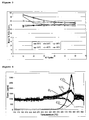
- Figure 1 illustrates the mean % NO conversion (from the 10 th cycle to the 60 th cycle) showing that the sample did not change conversion during time demonstrating a complete reduction of the NO x stored.
- the C1 catalyst showed from 200 to 400°C a high conversion with values higher than 90%, reducing the NO stored to N 2 and H 2 O without producing NH 3 .
- T > 400°C the conversion decreased because the sample during the reduction step desorbed NO ( fig. 2 ).
- Table 1 Test conditions for NO conversion tests in test 1 TEMPERATURE CYCLES Test 1 200°C 60 200-250°C (ramp 5°C/min.) 4 250°C 60 Test 2 300°C 60 300-350°C (ramp 5°C/min.) 4 350°C 60 Test 3 400°C 60 400-450°C (ramp 5°C/min.) 4 450°C 60
- the storage capacity of the catalysts C1 ( Fig. 2 ) and C2 ( Fig. 3 ) were compared as a function of the reaction temperature.
- Figure 2 shows the mean % NO conversion (from the 10th cycle to the 60th cycle) showing that between 200 and 350°C, the catalyst did not show a saturation with high NO conversion (85-95%) and a high efficiency reducing all the NOx adsorbed species to N 2 and H 2 O.
- the catalyst did not adsorb all the NO fed (mean % NO conversion around 50% and 30% respectively), because in the presence of CO 2 the storage capacity of C1 decreased compared to example 1.
- the storage capacity values are a function of the reaction temperature, even if the presence of CO 2 , slightly modifies the storage behaviour.
- the comparative catalyst C2 showed a lower NSR activity between 200 and 350°C.
- Table 2 Test conditions for NO conversion test in Test 2 TEMPERATURE CYCLES Test 1 200°C 60 200-250°C (ramp 5°C/min.) 4 250°C 60 Test 2 300°C 60 300-350°C (ramp 5°C/min.) 4 350°C 60 Test 3 400°C 60 400-450°C (ramp 5°C/min.) 4 450°C 60
- the NSR activity was studied without SO 2 , then feeding SO 2 using a series of cyclic sequences of feed changes from lean conditions [120 seconds with 5% O 2 , NO (1004 ppm), CO 2 (13.3 %) and SO 2 (63 ppm) remaining He] to rich conditions [15 seconds with 2.5 % H 2 , NO (1004 ppm), CO 2 (13.3 %) and SO 2 (63 ppm) remaining He] and the temperature was changed from 200 to 400°C. For each isotherm (200, 250, 300, 350 and 400°C) the cycle was repeated 34 times. At the end the NSR activity was again analysed without the SO 2 presence.
- the C1 catalysts showed good catalytic behaviour during SO 2 exposure with a very good mean NO x conversion (Table 4), with very constant behaviour before, during and after SO 2 exposure.
- Table 3 Test conditions for NO conversion in Test 3 Temperature Cycles Temperature Cycles Temperature Cycles Temperature Cycles Test 1 before SO 2 200°C 34 250-300°C (ramp 5°C/min.) 4 350°C 34 200-250°C (ramp 5°C/min.) 4 300°C 34 350-400°C (ramp 5°C/min.) 4 250°C 34 300-350°C (ramp 5°C/min.) 4 400°C 34 Test 2 with SO 2 Temperature Cycles Temperature Cycles Temperature Cycles Temperature Cycles Temperature Cycles 200°C 34 250-300°C (ramp 5°C/min.) 4 350°C 34 200-250°C (ramp 5°C/min.) 4 300°C 34 350-400°C (ramp 5°C/min.) 4 250°C 34 300-350°C (
- the storage capacity of the catalysts C1 and C2 were compared as a function of the reaction temperature. In the tests high concentration of SO 2 and short time of reduction were used in order to achieve a faster and more significant poisoning. The tests were carried out in presence of SO 2 and in the end without SO 2 and the results were compared with those obtained with the fresh catalysts.
- the NSR activity was studied using a series of cyclic sequences of feed changes from lean conditions [120 s: 5% O 2 , NO (1004 ppm), CO 2 (13.3 %) and SO 2 (63 ppm) remaining He] to rich conditions [15 s: 2.5 % H 2 , NO (1004 ppm), CO 2 (13.3 %) and SO 2 (63 ppm) remaining He] and the temperature was changed is the range 200-400°C. For each isotherm (200, 250, 300, 350 and 400°C) the cycle was repeated 34 times. At the end the NSR activity was again analysed without the SO 2 presence.
- the catalyst-soot mixture was heated in a 200 ml/min. flow of NO (1006 ppm), O 2 (10%) and H 2O (3%) remaining He. At the end of ramp (500°C) the support PP 6889-650 showed 62.5% of soot oxidation.
- the soot oxidation and NO x activity were studied by mass spectrometry and chemiluminescence.
- the catalyst-soot mixture was heated in a 200 ml/min. flow of NO (1006 ppm), O 2 (10%) and H 2 O (3%) remaining He.
Landscapes
- Chemical & Material Sciences (AREA)
- Engineering & Computer Science (AREA)
- Organic Chemistry (AREA)
- Chemical Kinetics & Catalysis (AREA)
- Materials Engineering (AREA)
- Environmental & Geological Engineering (AREA)
- Health & Medical Sciences (AREA)
- Biomedical Technology (AREA)
- Combustion & Propulsion (AREA)
- Analytical Chemistry (AREA)
- General Chemical & Material Sciences (AREA)
- Oil, Petroleum & Natural Gas (AREA)
- Life Sciences & Earth Sciences (AREA)
- Geology (AREA)
- Inorganic Chemistry (AREA)
- Catalysts (AREA)
Abstract
The present invention relates to a catalyst for the reduction of nitrogen oxides in exhaust gas comprising a nitrogen storage material consisting of a Mg/Al mixed oxide with a potassium content in the range of 3 to 15 wt% further comprising a metal from the platinum group. Further the present invention relates to a process for preparing the catalyst.
Description
- The present invention relates to a catalyst for the reduction of nitrogen oxides in exhaust gas comprising a nitrogen storage material consisting of a Mg/Al mixed oxide with a potassium content in the range of 3 to 15 wt% further comprising a metal from the platinum group. Further, the present invention relates to a process for preparing the catalyst.
- In the field of gasoline engines, so-called lean burn engines have been developed in order to reduce fuel consumption, which are fueled with lean air/fuel mixtures when operating under partial load. A lean air/fuel mixture contains a higher concentration of oxygen than necessary for complete combustion of the fuel. The corresponding exhaust gases then contain an excess of the oxidizing components oxygen and nitrogen oxides (NOx) compared to the reducing exhaust gas components carbon monoxide (CO), hydrogen and hydrocarbons (HC). Lean exhaust gas usually contains 3 to 15 vol.-% oxygen. However, during operation under load and full load, stoichiometric or even substoichiometric, i.e. rich, air/fuel mixtures are used even in lean burn engines.
- Diesel engines on the other hand usually run under operating conditions with highly superstoichiometric air/fuel mixtures. Only in recent years have diesel engines been developed that can also be operated with rich air/fuel mixtures for short periods of time.
- Due to the high oxygen content of the exhaust gases from lean burn engines, the nitrogen oxides contained therein cannot be continuously reduced to nitrogen in combination with a simultaneous oxidation of hydrocarbons and carbon monoxide by means of so-called three-way catalysts as is the case in stoichiometrically operated gasoline engines. Rather, with these catalysts a so-called temperature window for the reduction of the nitrogen oxides, which depends on the exhaust gas temperature, is observed. An increase in the exhaust gas temperature results in an initial increase in the nitrogen oxides conversion. At a certain temperature the conversion rate reaches a maximum and at higher temperatures the conversion rate recedes back to zero. Within the temperature window, the remaining hydrocarbons that are always still present in lean exhaust gas function as reducing agents for the nitrogen oxides.
- The position and width of the temperature window as well as the maximum nitrogen oxide conversion within the temperature window depend on the formulation of the catalyst and the residual hydrocarbon content of the exhaust gas. Conventional three-way catalysts only show a low nitrogen oxides conversion within the temperature window. However, so-called HC-DeNOx catalysts were developed, which exhibit a maximum nitrogen oxides conversion in the temperature window of up to 60% at a temperature in the range of 180 to 250°C. The width of the temperature window is only about 50°C.
- Despite the relatively high nitrogen oxide conversion rate within the temperature window, these catalysts only provide an average nitrogen oxide conversion of less than 30% throughout the standardized driving cycle MVEG-A.
- In order to improve this situation, so-called nitrogen oxides storage catalysts were developed which store the nitrogen oxides contained in lean exhaust gas in the form of nitrates.
- The mechanism of nitrogen oxides storage catalysts is described in detail in the SAE document, SAE 950809. Accordingly, nitrogen oxides storage catalysts consist of a catalyst material that commonly is applied on an inert, ceramic or metal honeycomb carrier, a so-called carrier, in the form of a coating. The catalyst material comprises the nitrogen oxides storage material and a catalytically active component. The nitrogen oxides storage material in turn consists of the actual nitrogen oxides storage component, deposited in highly dispersed form on a support material.
- Basic alkali metal oxides, alkaline earth metal oxides and rare earth metal oxides, and in particular barium oxide, which react with nitrogen dioxide to form the corresponding nitrates, are predominantly used as storage components. It is known that in air these materials are mostly present in the form of carbonates and hydroxides. These compounds are also suitable for storing the nitrogen oxides. Thus, whenever basic storage oxides are mentioned in the present invention, this also includes the corresponding carbonates and hydroxides.
- Noble metals of the platinum group are typically used as catalytically active components, which as a rule are deposited on the support material together with the storage component. Active aluminum oxide with a large surface area is usually used as support material. However, the catalytically active components can also be applied on a separate support material such as for example active aluminum oxide.
- It is the task of the catalytically active components to convert carbon monoxide and hydrocarbons to carbon dioxide and water in the lean exhaust gas. Furthermore, they should oxidize the nitrogen monoxide portion of the exhaust gas to nitrogen dioxide so that it can then react with the basic storage material to form nitrates (storage phase). An increasing incorporation of the nitrogen oxides in the storage material causes a decrease in the material's storage capacity, which has to be regenerated from time to time. For this purpose, the engine is operated for a short period of time with stoichiometric or rich air/fuel mixtures (referred to as regeneration phase). In the reducing conditions of the rich exhaust gas, the formed nitrates decompose to nitrogen oxides NO and, with the use of carbon monoxide, hydrogen and hydrocarbons as reducing agents, are reduced to nitrogen while water and carbon dioxide are formed. These catalysts are therefore also referred to as Nitrogen-Storage-Reduction (NSR) Catalyst.
- During the operation of the nitrogen oxides storage catalyst, the storage phase and the regeneration phase regularly alternate. Usually, the storage phase lasts between 60 and 120 seconds, while the regeneration phase is completed in less than 20 seconds.
- Nitrogen oxide storage catalysts allow considerably higher nitrogen oxides conversion rates in a larger temperature window than HC-DeNOx catalysts. Their nitrogen oxides conversions meet the exhaust limits according to the Euro IV standard, the introduction of which is planned for 2005.
- However, in order to improve the safety of operation and long-term stability of these catalysts, it is necessary to increase their thermal stability, widen their temperature window and further improve the nitrogen oxides conversions attainable in that window.
- Based on the foregoing, there is a need in the art for a catalyst for the prevention of nitrogen oxides in the exhaust gas from combustion engines, which has an improved thermal stability, a wider temperature window and a higher nitrogen oxides conversion rate in this window than conventional nitrogen oxides storage catalysts.
- Hydrotalcites are metal hydroxides having a layer lattice and belonging to the group of anionic clay minerals. Metal hydroxides are important precursors for the production of metal oxides used for instance as raw materials for refractories, ceramics, and supports for heterogeneous catalysts. In nature, metal hydroxides predominantly occur in the form of mixed metal hydroxides. There are numerous clay minerals that can be characterised by their layer lattice. The great majority of clay minerals are cationic ones. In these metal hydroxides, cations, e.g. Na+, Ca2+, etc., are located between the negatively charged layers. In anionic clay minerals which are far less common, anions are located between the positively charged layers of the metal hydroxide. A large number of these anionic clay minerals are hydroxides of metals of the main group, namely magnesium and aluminium, and hydroxides of transition metals, such as nickel, chromium, zinc, etc. The structure of these clay minerals can be derived from the brucite structure of magnesium hydroxide Mg(OH)2. In this structure, some of the divalent Mg(OH)6 4- octahedra are replaced by Al(OH)6 3- octahedra. Examples of these minerals are meixnerite having the idealised unit cell formula Mg6Al2(OH)18·4 H2O and hydrotalcite (Mg6Al2(OH)16CO3·4 H2O). The magnesium : aluminium atomic ratios can typically be varied between 1.2 and 4.0. The metal hydroxide octahedra share adjacent edges to form layers. In addition to water, interstitial anions required for balancing the charge are located between the layers. The anion nature can be simple, e.g. OH-, CO3 2-, Cl- or SO4 2-, or complex, as for instance in large, organic or inorganic anions.
- The use of hydrotalcite as part of a NSR catalyst was proposed in
US 6,858,193 where the hydrotalcite acts as support for additional storage material like BaO2, Ceria/Zirconia, La2O3 etc. - The problem underlying the present invention was therefore to provide a further catalyst useful in the reduction of nitrogen oxides in exhaust gas with a simpler structure and less components.
- The underlying problem of the invention is solved by a catalyst for the reduction of nitrogen oxides in exhaust gas comprising a nitrogen storage material consisting of a Mg/Al mixed oxide with a potassium content in the range of 3 to 15 wt%.
- Surprisingly it was found that the catalyst according to the invention does not need further storage material like BaO, Ce/ZrO2 etc. as discussed in the prior art. Further, the catalyst according to the invention has a better stability with respect to activity after several regeneration steps (see example). Further, it is much more sulfur-resistant than prior art NSR-catalysts. The improvement in activity over prior-art catalyst is in the range of 10-30 %, as exemplified in table 5 below.
- Unexpectedly, the catalyst according to the invention can oxidize soot and reduce NOx simultaneously, as shown below.
- Therefore, it can be used as a catalyst for NOx reduction and as a DPF (diesel particulate filter) coating at the same time as well. The present catalyst can therefore be used as a coating on a wall flow filter as known in the art.
- Preferably the catalyst according to the invention has a Mg/Al ratio in the Mg/Al mixed oxide in the range of from 1.5 to 3.5.
- It is further advantageous if the catalyst has a BET surface of >50 m2/g which is beneficial for the progress of the catalytic reaction(s), since a higher surface leads to a faster reaction rate.
- In most preferred embodiments of the present invention, the Mg/Al mixed oxide material is a hydrotalcite compound. The term "hydrotalcite" refers, as already mentioned above, generally to Hydrotalcite-type mixed Mg/Al oxide compounds, wherein the basis compound "hydrotalcite" has the general formula Mg6Al2(OH)16CO3·4H2O. A comprehensive survey can be found in: Allmann, R. and H.P. Jepsen (1969) Die Struktur des Hydrotalkits. Neues Jahrb. Mineral., Monatsh., 544-551.
- Synthetic hydrotalcite-like layered double hydroxide (LDHs) compounds can be used in the invention as well. LDHs are mixed metal hydroxides with the general formula [M1-x +2Mx +3(OH)2][Am] x/m·nH2O where M+2 and M+3 represent divalent and trivalent cations at the octahedral sites within the hydroxyl layers, x is equal to the ratio of M+3/(M+2 + M+3) with a value varying in the range of 0.17 to 0.50 and A-m is an exchangeable interlayer anion. LDHs have the ability to accommodate a large variety of divalent and trivalent cations and the formation of well-dispersed mixed oxides upon controlled thermal decomposition.
- Specifically preferred formulae for the hydrotalcite compounds of the catalyst of the present invention are selected from the group consisting of Mg6Al2(OH)18· 4 H2O, Mg6Al2(CO3) (OH)16 •4H2O, Mg0.67Al0.33 (OH)2Cl0.33 ·0.6
H 20, Mg0.69Al0.31(OH)2.013(CO3)0.15·0.30H2O, Mg0.74Al0.26(OH)2(CO3)0.13·0.39H2O, Mg0.67Al0.33(OH)2(CO3)0.16·0.69H2O, and Mg0.66Al0.34(OH)2(CO3)0.17·0.70H2O. As already stated above, these compounds contain potassium as an interlayer cation in accordance with the present invention. - The catalyst according to the invention comprises further a metal from the platinum group, which is preferably present in an amount of 0.2 to 2 wt% based on the total weight of the catalyst. Suitable platinum group metals are Pt, Pd, Ir, Rh, and mixtures thereof, especially preferred is platinum.
- The problem is further solved by a process for the preparation of the catalyst according to the invention, wherein the process comprises the steps of
- a) providing an aqueous KOH solution
- b) addition of Al(OH)3
- c) addition of a MgCO3 suspension
- d) stirring
- e) isolating the product
- Surprisingly, it has been found that the provision of the KOH solution in the first step leads to the desired product containing 3 to 15 wt% potassium as intercalating cation. The process according to the invention is different from hydrotalcite syntheses in prior art, where the intercalating cation was introduced only after synthesis of the hydrotalcite per se.
- Preferably step b) of the process is carried out at a temperature in the range of from 60 to 90°C preferably 70 - 80°C.
- Al(OH)3 is added preferably added as a solid to avoid side reactions due to solvation in water, where a number of hydrated Al-hydroxo species with different stoichiometric compositions would be present.
- Typically, the isolation of the product is carried out by filtering off the resulting suspension, but equivalent means like centrifuging etc. are also within the scope of a person skilled in the art.
- It is preferred that the stirring step d) is carried out in a temperature range from 70 to 100°C to accelerate the reaction process and to improve the yield of the reaction.
- The KOH solution in step a) has preferably a concentration of 10 - 60 Vol%. A concentration of lower than 10 Vol% would not lead to the desired product, the upper limit is given by the maximum concentration of KOH in water. Especially preferred is a concentration of ca. 40-50 %.
- The molar ratio of the starting materials Al(OH)3/KOH/MgCO3 is from 1/0.5/0.9 to 1/2.1/3, especially preferred is a ratio of 1/1.6/2.
- After isolation of the filtered product it is dried at ca. 70-90°C and subsequently impregnated by preferably the incipient wetness method with an aqueous solution of a metal salt from the platinum group, preferably a nitrate, amine, carboxylate, chloride or bromine salt. After impregnation, the product is calcined in a temperature range of from 600 to 900°C to yield the catalytically active species.
- The invention is further illustrated by way of figures and the examples which are not meant to be limiting the scope of the present invention.
- Fig 1
- shows the NSR NO-He capacity during sequences of 60 cycles for a catalyst according to the invention..
- Fig 2
- shows the NSR NO/CO2 capacity in the presence of CO2 during sequences of 60 cycles for a catalyst according to the invention.
- Fig 3
- shows the NSR NO-He capacity in the presence of CO2 during sequences of 60 cycles for a catalyst of prior art.
- Fig 4
- shows the results of the soot oxidation over a catalyst according to the invention
- Fig 5
- shows the soot oxidation for the catalysts C1, C2, C3 and the support
- A K-aluminate solution was prepared by slowly adding 0,91 mole Al(OH)3 in solid form to a KOH solution (1,6 mole KOH as an aqueous solution with 50% KOH content) at a temperature of 60 to 90 °C preferably 70 - 80°C. It is understood that the potassium content can be varied by variation of the KOH concentration in the KOH-solution. Deionized water (111 mole) was filled in a 200 l reactor and MgCO3 (2 mole) was added slowly under stirring. This suspension was heated by a steam lance to 90°C and mixed with the K-aluminate solution over a period of < 30 min under gentle stirring. After addition, the mixture was stirred at 90°C for one hour. The resulting suspension was then filtered by a filter press without washing the material to obtain the desired potassium containing Mg/Al mixed oxide.
- The material had a potassium content of 4,7 % and a specific surface area of 75 m2/g. The material was characterized by XRD as potassium containing "Meixnerite" Mg6Al2(OH)18 * 4 H2O wherein K+ is present as an interlayer cation in the form of an oxide or carbonate.
- Hydrotalcite (HT)-based 1.0 wt. % Pt catalysts (1Pt/Hydrotalcite) were obtained starting from hydrotalcite HT PP6889 (ratio Mg/Al = 2.16 potassium content: 10.8 wt%); prepared in accordance with Example 1, but with different KOH concentration precursors and heated under N2 flow at 650°C (PP6889-650). The hydrotalcite precursors were impregnated with 1.0 wt. % Pt by incipient wetness impregnation using an aqueous Pt(NH3)2(NO2)2 solution. After impregnation, the catalysts were dried at 80°C overnight and then heated under N2 flow at 550°C for 12 h. The surface area of the catalyst C 1 was 52 m2/g.
- A conventional storage catalyst was prepared, comprising a storage material (17 wt. % Ba based on the total weight of the catalyst), the noble metal (1 wt.% Pt) over commercial γ-Al2O3. This reference catalyst (17Ba-1Pt/γ-Al2O3) is also widely referred to as the "Toyota-type catalyst" [P. Engström, et al. Appl. Catal. 22 (1999) L241].
- The catalyst was prepared according to literature procedures [SAE Technical Paper 2002-010057 (2002).] with a commercial γ-Al2O3 (Sasol, D) support and was impregnated by the incipient wetness method, using at first a Pt(NH3)2(NO2)2 solution and then the Ba(CH3COO)2 solution. After each impregnation the sample was dried at 90°C overnight and then heated under N2 flow (100 ml/min) at 550°C for 12 h. The surface area of the catalyst C2 was 144 m2/g.
- Catalyst C3 was prepared from a HT-based Pt (1 wt.% Pt)catalyst , obtained from a commercial HT precursor (Mg2+:Al3+ = 66:34 as atomic ratio, by CONDEA (D); surface area: 214 m2/g [according to
EP 807086 A1 - The final powders of the C1, C2 and C3 catalysts were formed to particles with a particle size in the range of 0.250-0.600 mm after grinding and sieving, which were then activated at 350°C for 1 h in a 100 ml/min flow of H2 in He (20:80 v/v), followed by mild re-oxidation at 80°C for 1 h in a 100 ml/min flow of O2 in He (20:80 v/v).
- The NO conversion (during all cycles) was calculated by the following formula:

- The NO conversion was calculated every 10 cycles (10th, 20th, 30th, 40th, 50th, 60th). Thereby it was possible to analyse the NO conversion of the catalyst versus time at the same temperature.
- 0.5085 grams of C1 (0.250-0.600 mm sized particles) were placed in a quartz flow micro-reactor and heated under He flow at the temperature of the reaction (Table 1).
- The NSR activity was studied using a series of cyclic sequences of feed changes from lean conditions (120 seconds with 5% O2, 990 ppm NO, remaining He) to rich conditions (18 seconds with 2.5% H2, 990 ppm NO, remaining He) for a total flow of 200 ml/min.. Each catalytic test was repeated sixty (60) times at the same temperature (Table 1).
-
Figure 1 illustrates the mean % NO conversion (from the 10th cycle to the 60th cycle) showing that the sample did not change conversion during time demonstrating a complete reduction of the NOx stored. - The C1 catalyst showed from 200 to 400°C a high conversion with values higher than 90%, reducing the NO stored to N2 and H2O without producing NH3. When the temperature increased (T > 400°C), the conversion decreased because the sample during the reduction step desorbed NO (
fig. 2 ).Table 1: Test conditions for NO conversion tests in test 1 TEMPERATURE CYCLES Test 1 200° C 60 200-250°C (ramp 5°C/min.) 4 250° C 60 Test 2300° C 60 300-350°C (ramp 5°C/min.) 4 350° C 60 Test 3 400° C 60 400-450°C (ramp 5°C/min.) 4 450° C 60 - The storage capacity of the catalysts C1 (
Fig. 2 ) and C2 (Fig. 3 ) were compared as a function of the reaction temperature. - 0.5085 grams of C1 or 0,4660 grams of C2 (0.250-0.600 mm particles) were placed in the quartz flow micro-reactor and heated under He flow at the temperature of reaction (Table 2). The NSR activity was studied in presence of CO2 using a series of cyclic sequences of feed changes from lean conditions (120 seconds with 5% O2, 1008 ppm NO, 10,8 CO2, remaining He) to rich conditions (18 seconds with 2.5% H2, 1008 ppm NO, 10,8 CO2, remaining He) for a total flow of 200 ml/min.. Each catalytic test was repeated sixty (60) times at the same temperature (Table 2).
-
Figure 2 shows the mean % NO conversion (from the 10th cycle to the 60th cycle) showing that between 200 and 350°C, the catalyst did not show a saturation with high NO conversion (85-95%) and a high efficiency reducing all the NOx adsorbed species to N2 and H2O. - At 400°C and 450°C, the catalyst did not adsorb all the NO fed (mean % NO conversion around 50% and 30% respectively), because in the presence of CO2 the storage capacity of C1 decreased compared to example 1. The storage capacity values are a function of the reaction temperature, even if the presence of CO2, slightly modifies the storage behaviour.
- The comparative catalyst C2 showed a lower NSR activity between 200 and 350°C.
Table 2: Test conditions for NO conversion test in Test 2TEMPERATURE CYCLES Test 1 200° C 60 200-250°C (ramp 5°C/min.) 4 250° C 60 Test 2300° C 60 300-350°C (ramp 5°C/min.) 4 350° C 60 Test 3 400° C 60 400-450°C (ramp 5°C/min.) 4 450° C 60 - 0.5085 grams of C1 (0.250-0.600 mm particles) were placed in the quartz flow micro-reactor and heated under He flow at the reaction temperature (Table 3).
- Higher concentrations of SO2 and short time of reduction were fed in our tests in order to achieve a faster and more significant poisoning.
- The deactivation of the C1 catalyst by SO2 was studied mainly with regard to the influence of SO2 during several cycles of NSR at different temperatures.
- Uptake experiments were carried out using NO (1004 ppm), CO2 (13.3 %) and SO2 (63 ppm) in He monitoring the gas composition at the reactor outlet by mass spectrometry and chemiluminescence.
- The NSR activity was studied without SO2, then feeding SO2 using a series of cyclic sequences of feed changes from lean conditions [120 seconds with 5% O2, NO (1004 ppm), CO2 (13.3 %) and SO2 (63 ppm) remaining He] to rich conditions [15 seconds with 2.5 % H2, NO (1004 ppm), CO2 (13.3 %) and SO2 (63 ppm) remaining He] and the temperature was changed from 200 to 400°C. For each isotherm (200, 250, 300, 350 and 400°C) the cycle was repeated 34 times. At the end the NSR activity was again analysed without the SO2 presence.
- The C1 catalysts showed good catalytic behaviour during SO2 exposure with a very good mean NOx conversion (Table 4), with very constant behaviour before, during and after SO2 exposure.
Table 3: Test conditions for NO conversion in Test 3 Temperature Cycles Temperature Cycles Temperature Cycles Test 1 before SO2 200°C 34 250-300°C
(ramp 5°C/min.)4 350°C 34 200-250°C
(ramp 5°C/min.)4 300°C 34 350-400°C
(ramp 5°C/min.)4 250°C 34 300-350°C
(ramp 5°C/min.)4 400°C 34 Test 2 with SO2Temperature Cycles Temperature Cycles Temperature Cycles 200°C 34 250-300°C
(ramp 5°C/min.)4 350°C 34 200-250°C
(ramp 5°C/min.)4 300°C 34 350-400°C
(ramp 5°C/min.)4 250°C 34 300-350°C
(ramp 5°C/min.)4 400°C 34 Test 3 after SO2 Temperature Cycles Temperature Cycles Temperature Cycles 200°C 34 250-300°C
(ramp 5°C/min.)4 350°C 34 200-250°C
(ramp 5°C/min.)4 300°C 34 350-400°C
(ramp 5°C/min.)4 250°C 34 300-350°C
(ramp 5°C/min.)4 400°C 34 Table 4: Mean NO x conversion (%) at different temperatures and feedings for C1. C1 Mean NOx conversion (%) Test 200°C 250°C 300°C 350°C 400°C NO + CO2 before SO2 54 50 48 33 14 NO + CO2 with SO2 54 50 49 33 14 NO + CO2 after SO2 58 59 56 42 34 - The storage capacity of the catalysts C1 and C2 were compared as a function of the reaction temperature. In the tests high concentration of SO2 and short time of reduction were used in order to achieve a faster and more significant poisoning. The tests were carried out in presence of SO2 and in the end without SO2 and the results were compared with those obtained with the fresh catalysts.
- The activity is expressed as % variation of mean NOx conversion using the activity of the fresh catalyst as a reference:

- Mean NOx conversion: = [NO ads/NO feed]*100 [during 135 sec. of each the cycle]; NO ads = NO feed - NO des.
- 0.50 grams of C1 or grams of C2 (0.250-600 mm particles) were placed in the quartz flow micro-reactor and heated under He flow at temperature of reaction (Table 1).
- The NSR activity was studied using a series of cyclic sequences of feed changes from lean conditions [120 s: 5% O2, NO (1004 ppm), CO2 (13.3 %) and SO2 (63 ppm) remaining He] to rich conditions [15 s: 2.5 % H2, NO (1004 ppm), CO2 (13.3 %) and SO2 (63 ppm) remaining He] and the temperature was changed is the range 200-400°C. For each isotherm (200, 250, 300, 350 and 400°C) the cycle was repeated 34 times. At the end the NSR activity was again analysed without the SO2 presence.
- The results are reported in table 5. The C1 showed a constant behaviour; during and after SO2 exposure it was possible to determine the same mean NOx conversion value. While the C2 showed a very high deactivation and only after during the test without SO2 at high temperature (350-400°C) the catalyst showed the same mean NOx conversion.
Table 5: % variation at different temperature and feedings for C1 and C2. C1 % variation 200°C 250°C 300°C 350°C 400°C NO + CO2 with SO 2100 100 102 100 100 NO + CO2 after SO2 107 118 117 127 243 C2 % variation 200°C 250°C 300°C 350°C 400°C NO + CO2 with SO2 78 74 82 82 82 NO + CO2 after SO2 69 74 88 111 111 - 0.4012 grams of the support PP6889-650 without noble metal (0.250-0.600 mm particles) were mixed with 0.1005 grams of synthetic soot and placed over the quartz flow micro-reactor and heated under He flow at a temperature of reaction (Table 6).
- The catalyst-soot mixture was heated in a 200 ml/min. flow of NO (1006 ppm), O2 (10%) and H2O (3%) remaining He.
At the end of ramp (500°C) the support PP 6889-650 showed 62.5% of soot oxidation. - Without the noble metal the PP 6889-650 can not reduce the NO feed and the reductions of NO is 0% (average for all test). The soot is largely converted to CO2 below 440°C (
Fig. 3 ).Table 6: Scheme of the catalytic tests with soot TEMPERATURE Test with soot 150°C 1 min. 150-450°C (ramp 2°C/min.) 150 min. 450° C 10 min. 450-500°C (ramp 2°C/min.) 25 min. 500° C 10 min. - The soot oxidations of the catalysts C1, C2 and C3 were compared as a function of the reaction temperature (
Fig. 5 ). - The soot oxidation and NOx activity were studied by mass spectrometry and chemiluminescence. The catalyst-soot mixture was heated in a 200 ml/min. flow of NO (1006 ppm), O2 (10%) and H2O (3%) remaining He.
- C1:
- 0.3620 grams of the catalyst were mixed with 0.0905 grams of synthetic soot and placed over the quartz flow micro-reactor and heated under He flow at temperature of reaction (following the scheme of Table 7).
- C2:
- 0.4003 grams of the catalyst were mixed with 0.1008 grams of synthetic soot and placed over the quartz flow micro-reactor and heated under He flow at a temperature of reaction (following the scheme of Table 7).
- C3:
- 0.5040 grams of the catalyst were mixed with 0.1250 grams of synthetic soot and placed over the quartz flow micro-reactor and heated under He flow at a temperature of reaction (following the scheme of Table 7).
- The results about soot oxidation and NO reduction are reported in Table 8. For C1 the soot is largely converted to CO2 below 430°C (
Fig. 4 ).Table 8: Soot oxidation and NO reduction for the catalysts. Catalyst Soot oxidation (%) NO reduction (%) C1 99 40 C2 20 13 C3 70 10
| TEMPERATURE | ||
| Test with | 150°C | 1 min. |
| 150-450°C (ramp 2°C/min.) | 150 min. | |
| 450° | 10 min. | |
| 450-500°C (ramp 2°C/min.) | 25 min. | |
| 500° | 10 min. |
Claims (19)
- Catalyst for the reduction of nitrogen oxides in exhaust gas comprising a nitrogen storage material consisting of a Mg/Al mixed oxide with a potassium content in the range of 3 to 15 wt%.
- Catalyst according to claim 1, wherein the Mg/Al ratio of the Mg/Al mixed oxide is in the range of from 1.5 to 3.5.
- Catalyst according to claim 3 with a BET surface of >50 m2/g.
- Catalyst according to claim 3, wherein the Mg/Al mixed oxide material is a hydrotalcite compound.
- Catalyst according to claim 4, wherein the hydrotalcite compound is selected from Mg6Al2(OH)18· 4 H2O,
Mg6Al2(CO3)(OH)16 ·4H2O, Mg0.67Al0.33 (OH)2Cl0.33 · 0.6H20,
Mg0.69Al0.31(OH)2.013(CO3)0.15·0.3 H2O,
Mg0.74Al0.26(OH)2(CO3)0.13·0.39H2O,
Mg0.67Al0.33(OH)2(CO3)0.16·0.69H2O, and
Mg0.66Al0.34(OH)2(CO3)0.17·0.70H2O - Catalyst according to claim 5, further comprising a metal from the platinum group.
- Catalyst according to claim 7, wherein the metal of the platinum group is present in an amount of 0.2 to 2 wt%.
- Catalyst according to claim 7, wherein the metal of the platinum group is platinum.
- Process for the preparation of a catalyst according to anyone of claims 1 to 8 comprising the steps ofa) Providing an aqueous KOH solutionb) Addition of Al(OH)3c) Addition of a MgCO3 suspensiond) Stirringe) Isolating the product
- Process according to claim 9, wherein step b) is carried out at a temperature in the range of 60-90°C.
- Process according to claim b) wherein Al(OH)3 is added as a solid.
- Process according to claim 11, wherein the isolation of the product is carried out by filtering.
- Process according to anyone of the preceding claims, wherein the stirring step d) is carried out in a temperature range from 70 to 100°C.
- Process according to claim 13, wherein the KOH solution in step a) has a concentration of 50 Vol%.
- Process according to claim 14 wherein the molar ratio of the starting materials Al(OH)3/KOH/MgCO3 is in the range of 1/0.5/0.9 to 1/2.1/3.
- Process according to anyone of the preceding claims wherein the filtered product is impregnated with an aqueous solution of a metal salt from the platinum group.
- Process according to claim 16, wherein the product is calcined after impregnation.
- Catalyst obtainable by a process according to anyone of the preceding claims 9 to 17.
- Use of a catalyst according to anyone of claims 1 to 8 or 18 for simultaneous oxidation of soot and the reduction of nitrogen-oxides.
Priority Applications (1)
| Application Number | Priority Date | Filing Date | Title |
|---|---|---|---|
| EP08014006A EP2153894A1 (en) | 2008-08-05 | 2008-08-05 | Catalyst for the reduction of nitrogen oxides in exhaust gas |
Applications Claiming Priority (1)
| Application Number | Priority Date | Filing Date | Title |
|---|---|---|---|
| EP08014006A EP2153894A1 (en) | 2008-08-05 | 2008-08-05 | Catalyst for the reduction of nitrogen oxides in exhaust gas |
Publications (1)
| Publication Number | Publication Date |
|---|---|
| EP2153894A1 true EP2153894A1 (en) | 2010-02-17 |
Family
ID=40361592
Family Applications (1)
| Application Number | Title | Priority Date | Filing Date |
|---|---|---|---|
| EP08014006A Withdrawn EP2153894A1 (en) | 2008-08-05 | 2008-08-05 | Catalyst for the reduction of nitrogen oxides in exhaust gas |
Country Status (1)
| Country | Link |
|---|---|
| EP (1) | EP2153894A1 (en) |
Cited By (3)
| Publication number | Priority date | Publication date | Assignee | Title |
|---|---|---|---|---|
| GB2477690B (en) * | 2008-12-04 | 2013-06-05 | Johnson Matthey Plc | NOx storage materials for sensor applications |
| WO2018114245A1 (en) * | 2016-12-19 | 2018-06-28 | Scg Chemicals Co., Ltd. | NOx STORAGE AND REDUCTION CATALYST AND METHOD FOR PREPARING THE SAME |
| CN110075833A (en) * | 2019-05-24 | 2019-08-02 | 北京市劳动保护科学研究所 | It is a kind of to remove NO simultaneouslyxWith the catalyst of carbon soot particles and preparation method thereof |
Citations (4)
| Publication number | Priority date | Publication date | Assignee | Title |
|---|---|---|---|---|
| EP0807086A1 (en) | 1995-02-03 | 1997-11-19 | Rwe-Dea Aktiengesellschaft Für Mineraloel Und Chemie | Process for producing hydrotalcites and their metal oxides |
| US20030125202A1 (en) * | 2001-11-30 | 2003-07-03 | Omg Ag & Co.Kg | Catalyst for lowering the amount of nitrogen oxides in the exhaust gas from lean burn engines |
| CN1775350A (en) * | 2005-12-02 | 2006-05-24 | 济南大学 | Diesel vehicle exhaust soot combustion and NOx storage-reduction dual-function catalyst and preparation method |
| WO2007005795A1 (en) * | 2005-07-01 | 2007-01-11 | Albemarle Netherlands Bv | Use of anionic clay in an fcc process |
-
2008
- 2008-08-05 EP EP08014006A patent/EP2153894A1/en not_active Withdrawn
Patent Citations (6)
| Publication number | Priority date | Publication date | Assignee | Title |
|---|---|---|---|---|
| EP0807086A1 (en) | 1995-02-03 | 1997-11-19 | Rwe-Dea Aktiengesellschaft Für Mineraloel Und Chemie | Process for producing hydrotalcites and their metal oxides |
| US6517795B1 (en) * | 1995-02-03 | 2003-02-11 | Sasol Germany Gmbh | Process for producing hydrotalcites and the metal oxides thereof |
| US20030125202A1 (en) * | 2001-11-30 | 2003-07-03 | Omg Ag & Co.Kg | Catalyst for lowering the amount of nitrogen oxides in the exhaust gas from lean burn engines |
| US6858193B2 (en) | 2001-11-30 | 2005-02-22 | Umicore Ag & Co. Kg | Catalyst for lowering the amount of nitrogen oxides in the exhaust gas from lean burn engines |
| WO2007005795A1 (en) * | 2005-07-01 | 2007-01-11 | Albemarle Netherlands Bv | Use of anionic clay in an fcc process |
| CN1775350A (en) * | 2005-12-02 | 2006-05-24 | 济南大学 | Diesel vehicle exhaust soot combustion and NOx storage-reduction dual-function catalyst and preparation method |
Non-Patent Citations (3)
| Title |
|---|
| ALLMANN, R.; H.P. JEPSEN: "Die Struktur des Hydrotalkits", NEUES JAHRB. MINERAL., MONATSH., 1969, pages 544 - 551 |
| P. ENGSTROM ET AL., APPL. CATAL., vol. 22, 1999, pages 241 |
| ZHANG ET AL: "Diesel soot combustion on potassium promoted hydrotalcite-based mixed oxide catalysts", CATALYSIS COMMUNICATIONS, ELSEVIER SCIENCE, AMSTERDAM, NL, vol. 8, no. 11, 1 November 2007 (2007-11-01), pages 1621 - 1624, XP022262195, ISSN: 1566-7367 * |
Cited By (3)
| Publication number | Priority date | Publication date | Assignee | Title |
|---|---|---|---|---|
| GB2477690B (en) * | 2008-12-04 | 2013-06-05 | Johnson Matthey Plc | NOx storage materials for sensor applications |
| WO2018114245A1 (en) * | 2016-12-19 | 2018-06-28 | Scg Chemicals Co., Ltd. | NOx STORAGE AND REDUCTION CATALYST AND METHOD FOR PREPARING THE SAME |
| CN110075833A (en) * | 2019-05-24 | 2019-08-02 | 北京市劳动保护科学研究所 | It is a kind of to remove NO simultaneouslyxWith the catalyst of carbon soot particles and preparation method thereof |
Similar Documents
| Publication | Publication Date | Title |
|---|---|---|
| KR101011830B1 (en) | Mixed Metal Oxide Catalysts for Nitrogen Oxide Decomposition | |
| EP1870158B1 (en) | Transition metal-substituted hydrotalcite catalyst for removing nitrogen oxides from the exhaust gas of diesel engine by storage-reduction. | |
| US10478808B2 (en) | Synthesis of oxygen-mobility enhanced CeO2 and use thereof | |
| EP2039425B1 (en) | Process for production of an exhaust gas clean-up catalyst | |
| US6313063B1 (en) | Catalyst support material | |
| KR100535165B1 (en) | Nitrogen oxide storage material, process for the production thereof and nitrogen oxide storing catalyst prepared from nitrogen oxide storage material | |
| US5830822A (en) | High temperature resistant oxidation catalyst, a process for its preparation and a combustion process using this catalyst | |
| US6419890B1 (en) | SOX tolerant NOX trap catalysts and methods of making and using the same | |
| US7504085B2 (en) | Alumina-based perovskite catalysts and catalyst supports | |
| US6586481B2 (en) | Catalyst based on cobalt and its use in the fischer-tropsch process | |
| US8512662B2 (en) | Method for adsorbing and decomposing lean nitrogen oxide using a mixed metal oxide catalyst | |
| Ivanova | Physicochemical and catalytic properties of systems based on CeO2 | |
| KR101473440B1 (en) | Mixed oxide catalyst materials for treating an exhaust gas, preparing methods thereof and methods for treating the exhaust gas using the same | |
| US20100227758A1 (en) | Alumina-Based Perovskite Catalysts and Catalyst Supports | |
| KR101380642B1 (en) | Dual-stage method for the reactivation of thermally aged nitrogen oxide storage catalysts | |
| JP2838336B2 (en) | Catalyst for catalytic reduction of nitrogen oxides | |
| EP2954950A1 (en) | CATALYST FOR PURIFYING NOx OCCLUSION REDUCTION-TYPE EXHAUST GAS AND EXHAUST GAS PURIFICATION METHOD USING SAID CATALYST | |
| US11433376B2 (en) | Mixed oxide with enhanced resistance and NOx storage capacity | |
| US6797247B2 (en) | Material with a channel structure for eliminating oxides of nitrogen | |
| Iglesias-González et al. | CuO/CexSn1− xO2 catalysts with low tin content for CO removal from H2-rich streams | |
| JPH06315634A (en) | Catalytic structure for nitrogen oxide catalytic reduction | |
| JP4974674B2 (en) | Complex oxide | |
| WO2019042911A1 (en) | Use of a mixed oxide to absorb nox | |
| JP6799885B2 (en) | Ceria-zirconia oxide-based oxygen absorption / release material in which rare earth oxide phases are hybridized | |
| JPH1199319A (en) | Waste gas purifying method |
Legal Events
| Date | Code | Title | Description |
|---|---|---|---|
| PUAI | Public reference made under article 153(3) epc to a published international application that has entered the european phase |
Free format text: ORIGINAL CODE: 0009012 |
|
| AK | Designated contracting states |
Kind code of ref document: A1 Designated state(s): AT BE BG CH CY CZ DE DK EE ES FI FR GB GR HR HU IE IS IT LI LT LU LV MC MT NL NO PL PT RO SE SI SK TR |
|
| AX | Request for extension of the european patent |
Extension state: AL BA MK RS |
|
| AKY | No designation fees paid | ||
| STAA | Information on the status of an ep patent application or granted ep patent |
Free format text: STATUS: THE APPLICATION IS DEEMED TO BE WITHDRAWN |
|
| 18D | Application deemed to be withdrawn |
Effective date: 20100818 |
|
| REG | Reference to a national code |
Ref country code: DE Ref legal event code: 8566 |