EP2153727A1 - Meat cutting method and apparatus for meat carcass and program for meat cutting procedure - Google Patents
Meat cutting method and apparatus for meat carcass and program for meat cutting procedure Download PDFInfo
- Publication number
- EP2153727A1 EP2153727A1 EP08752327A EP08752327A EP2153727A1 EP 2153727 A1 EP2153727 A1 EP 2153727A1 EP 08752327 A EP08752327 A EP 08752327A EP 08752327 A EP08752327 A EP 08752327A EP 2153727 A1 EP2153727 A1 EP 2153727A1
- Authority
- EP
- European Patent Office
- Prior art keywords
- incision
- meat
- making
- work
- cutter blade
- Prior art date
- Legal status (The legal status is an assumption and is not a legal conclusion. Google has not performed a legal analysis and makes no representation as to the accuracy of the status listed.)
- Granted
Links
Images


Classifications
-
- A—HUMAN NECESSITIES
- A22—BUTCHERING; MEAT TREATMENT; PROCESSING POULTRY OR FISH
- A22C—PROCESSING MEAT, POULTRY, OR FISH
- A22C17/00—Other devices for processing meat or bones
- A22C17/004—Devices for deboning meat
-
- A—HUMAN NECESSITIES
- A22—BUTCHERING; MEAT TREATMENT; PROCESSING POULTRY OR FISH
- A22B—SLAUGHTERING
- A22B7/00—Slaughterhouse arrangements
- A22B7/001—Conveying arrangements
- A22B7/005—Means for transferring carcasses from a conveying unit to a different one, e.g. hooking, unhooking
-
- A—HUMAN NECESSITIES
- A22—BUTCHERING; MEAT TREATMENT; PROCESSING POULTRY OR FISH
- A22C—PROCESSING MEAT, POULTRY, OR FISH
- A22C17/00—Other devices for processing meat or bones
- A22C17/0093—Handling, transporting or packaging pieces of meat
Definitions
- the invention relates to a method and apparatus for automating incision-making process made at a previous step before entering a deboning step of a leg part of a slaughtered domestic animal by use of a multi-axial multi-joint arm and an operation program for allowing the apparatus to carry out the incision-making.
- patent literature 1 is disclosed a semi-automated de-boning machine for carrying out de-boning of a pig thigh and a method of de-boning by use of the machine.
- pig thighs experience a pretreatment process, meat scrape-off process for scraping off meat adhering to the lower femurbone, and meat scrape-off process for scraping off meat adhering to the femurbone while the pig thighs are transferred in a state they are suspended with their ankles clamped with clampers attached to a transfer chain.
- the hipbone 4 including the hipbone and tailbone are removed and incisions are made to the meat along the lower femurbone (including tibia and fibula) and femurbone by an operator while the pig thigh is transferred hanging from the clamper.
- incisions are made with a cutter around the lower thigh and thigh of the pig thigh hanging from the clamper while scraping off the meat adhering to bones with a meat scraper.
- biomedical tissue such as muscle, tendon, and ligament adhering to the bones are cut, and meat is separated from the bones stepwise.
- These incisions are made with a cutter to cut biomedical tissue surrounding the bones at determined positions in longitudinal direction by rotating the pig thigh.
- patent literature 2 is disclosed a method and apparatus for automating a process of making incision into the thigh meat of poultry performed as a preprocessing in de-boning process of a poultry thigh.
- a thigh holding and an incision making devices are provided in an incision making station provided on a transfer route of a buffer conveyor, and the incision is made by the incision making device in a state the poultry thigh is held by the thigh holding device in a prescribed attitude.
- the present invention was made in light of problems in prior art and aims to automate incision-making process to thigh meat while accommodated to complicated 3-dimentional profile and make it possible to increase line speed of de-boning line, thereby increasing operation efficiency. Further, the invention aims to perform incision-making operation that enables de-boning operation of a thigh without damaging the thigh meat so that commodity value of the separated thigh meat is not decreased.
- the present invention proposed a method of making incision to a leg part of a slaughtered domestic animal in longitudinal direction using a multi-spindle multi-joint arm having at a forefront end thereof a cuter blade, wherein incision making processes include a first incision making process for making incision between a knuckle meat and an inner thigh meat around a femurbone, a second incision making process for cutting biomedical tissues around a lower femurbone and knee cap, and a third incision making process for making incision into a connecting part of the inner thigh meat to the femurbone to separate the inner thigh meat from the femurbone, whereby the third incision making process is performed after the first incision making process.
- incision making operation is automated by using a multi-spindle multi-j oint arm having at its forefront part a cutter blade.
- the cutter blade can be moved along the complicated 3-dimentional surfaces of bones to make incision between the bones and meat by using the multi-spindle multi j oint arm, thereby decreasing meat remained on the bones, resulting in increased yield of meat.
- the knuckle meat and inner thigh meat can be separated from the femurbone without damaging the meat. Therefore, commodity value of the knuckle meat and inner thigh meat is not degraded.
- trajectories of movement of the cutting blade are controlled by program-controlling the multi-spindle multi-joint arm under a program in which a trajectory of the cutter blade for each incision making and sequence of making incisions are set. The three incisions along surfaces of bones are made accurately in the determined order.
- All of the first to third incision making operations may be performed by a single multi-spindle multi-joint arm or may be performed by a plurality of multi-spindle multi-joint arms.
- efficiency of deboning the leg part can be increased.
- the incisions are made by allowing the cutter blade to move from the upper side downward while the leg part is transferred in a state it is hanged from a clamper with its ankle part held by the clamper and one of both side faces perpendicular to the transfer direction of the leg part is supported so that the leg part is not moved by force exerted on the leg part by the cutter blade.
- At least one of the incisions is made by configuring the cutter blade to move from the upper side downward while the leg part is transferred in a state it is hanging from a clamper with its ankle part held by the clamper and both side faces perpendicular to a transfer direction of the leg part are supported so that the leg part is not moved by force exerted on the leg part by the cutter blade.
- Ligaments and tendons are adhering strongly to bones in the upper part of the femoral head and it is necessary to make incision near the femoral head to move the cutter blade to move around the femoral head and further around the side surface of the knee cap. Therefore, it is preferable to support the leg part from both side faces thereof perpendicular to the transfer direction of the leg part.
- a plurality of kinds of incision making operation programs are provided to correspond to right leg part or left leg part as well as a variety of length of the leg part, judgment whether the leg part is a right one or left one and determination of length of the leg part are performed before the incisions are made, and an incision making operation program most suited for making incision to the leg part is selected from among the incision making operation programs based on the judgment and the determination.
- an incision making operation program most suited for individual leg part is selected to make incision. Therefore, high yield rate of meat can be obtained regardless of right or left leg part and long or short of length thereof.
- an apparatus for making incision to a slaughtered domestic animal having a multi-spindle multi-joint arm or arms, in which apparatus incisions are made in longitudinal direction of a leg part of the slaughtered domestic animal before deboning processing is performed, comprising; one or a plurality of multi-spindle multi-joint arms disposed along a deboning work line, each of the arms having a cutter blade at its forefront end and being controlled under an incision making operation program, whereby incision making operation consisting of a first incision making process for making incision between a knuckle meat and an inner thigh meat around a femurbone, a second incision making process for cutting biomedical tissues around a lower femurbone and knee cap, and a third incision making process for making incision into a connecting part of the inner thigh meat to the femurbone to separate the inner thigh meat from the femurbone, is performed in up
- the method of the invention can be implemented with the apparatus.
- the apparatus one or a plurality of multi-spindle multi-joint arms are arranged along a deboning operation line and incision making operation is performed by controlling the multi-spindle multi-joint arm or arms having cutter blade attached to the forefront part thereof under a incision making operation program or programs to make the first to third incisions.
- the cutter blade can be advanced to follow the surfaces of the bones and deboning can be performed with increased yield of meat without damaging knuckle meat and inner thigh meat.
- the cutter blade is supported by an elastic supporting device attached to the forefront end of the multi-spindle multi-joint arm such that the cutter blade is slidable in direction perpendicular to advance direction of the cutter blade and swingable about a shaft perpendicular to the side direction and advance direction of the cutter blade so that difference between a trajectory of movement of the cutter blade programmed in the incision making operation program and actual trajectory to be followed by the cutter blade due to difference in size of individual leg part is compensated by the elastic supporting of the cutter blade to allow the cutter blade to follow 3-dimentional profiles of surfaces of bones of the leg part.
- the cutter blade By supporting the cutter blade via the elastic supporting device, the cutter blade can be moved to follow the complicated three dimensional profile of surfaces of bones of the leg part compensating slight difference in profile of individual leg part. Therefore, deboning of leg part is made possible with decreased meat remaining on the bones even if there is considerable degree of individual difference in each leg part.
- An incision making operation program is configured to allow one or plurality of multi-spindle multi-joint arms to be operated to perform the incision making processes recited above.
- the incision making processes according to the invention can be performed under the program to achieve action and effect of the method of the invention.
- the incision making operation program of the invention may be created such that the first to third incisions are performed by a single multi-spindle multi-joint arm, or such that the first to third incisions are performed by a plurality of multi-spindle multi-joint arms.
- the program allows three multi-spindle multi-joint arms arranged along a transfer line of leg part to perform the first to third incisions sequentially.
- incision making operation in a method of making incision using a multi-spindle multi-joint arm or arms equipped with a cutter blade at its forefront end part along longitudinal direction of a leg part of a slaughtered domestic animal in a preceding step of deboning operation, incision making operation can be automated and incision along complicated three dimensional profile of the bones of the leg part is made possible by performing a first incision making process for making incision between a knuckle meat and an inner thigh meat around a femurbone; a second incision making process for cutting biomedical tissues around a lower femurbone and knee cap; and a third incision making process for making incision into a connecting part of the inner thigh meat to the femurbone to separate the inner thigh meat from the femurbone, and performing the third incision making process after the first incision making process.
- labor force is saved, incision making process capacity is increase, and yield of meat is increased.
- knuckle meat is separated from inner thigh meat first in the first incision making process, then the inner thigh meat is separated from the femurbone in the third incision making process, so each meat part can be separated without experiencing damage, as a result deboning is made possible without degrading commodity value of meat separated from the bone.
- the method of the invention can be practiced by composing an apparatus, having multi-spindle multi-joint arm or arms, in which incisions are made in longitudinal direction of a leg part of the slaughtered domestic animal before deboning process such that; it comprises one or a plurality of multi-spindle multi-joint arms disposed along a deboning work line, each of the arms having a cutter blade at its forefront end and being controlled under an incision making operation program, whereby incision making operation consisting of a first incision making process for making incision between a knuckle meat and an inner thigh meat around a femurbone, a second incision making process for cutting biomedical tissues around a lower femurbone and knee cap, and a third incision making process for making incision into a connecting part of the inner thigh meat to the femurbone to separate the inner thigh meat from the femurbone, is performed in upstream of a deboning line by controlling the arm or arms.
- the incision making operation program of the invention is made such that it allows the incision making operation of the invention to be performed by one or a plurality of multi-spindle multi-joint arms, and the cutter blade of the multi-spindle multi-joint arm is moved along the bones of the leg part following three dimensional profile of the surfaces of the bones, therefore deboning of the leg part can be automated, yield of meat is increased, and incision making processing capacity can be increased.
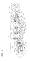
- FIG.1 is a plan view showing overall construction of the deboning apparatus of an embodiment of the present invention
- FIG.2 is a representation of all processing steps performed by the deboning apparatus.
- a pig leg part 1 (hereafter referred to as a work 1) includes a lower femurbone 2 (including tibia and fibula), a femurbone 3, a hipbone 4, a knee cap 6 positioned at a front part of the knee joint part 5 of the femurbone 3, and meat 7 surrounding these bones.
- a meat part surrounding the lower femurbone 2 consists of a calf meat part 7d (chimaki in Japanese) and shank 7e, and a meat part surrounding the femurbone consists of a knuckle meat part 7a (shintama in Japanese), inner thigh meat 7b, and outer thigh meat 7c of which the outer surface is covered with a fat layer 1a.
- the hipbone 4 is removed by an operator manually in a pretreatment station 20.
- an ankle part 8 of the work 1 deprived of the hipbone 4 (hereafter the work 1 deprived of the hipbone 4 is also referred to as work 1) is mounted on a transfer line of the deboning apparatus at a work mounting station 30 using a multi-spindle multi-joint arm 31.
- the work 1 (leg part) is clamped at its ankle to a clamper 11 fixed to a transfer chain 12 of the transfer line at random, regardless whether it is a right or left leg part.
- automated processes are carried out at stations from an initial incision making station 40 to a bone discharging station 110.
- the transfer chain 12 is installed horizontally and driven by a driving device 13 for the clamper to be circulated at a constant speed.
- the clamper 11 has a recession for receiving the ankle 8 of the work 1 and is fixed to the chain at an equal spacing.
- the clamper 11 is transferred along the circulation route formed by the transfer chain 12 horizontally at a constant speed while suspending the work 1.
- the work 1 is suspended in such an attitude that the fat layer 1a thereof is directed to the inner side of the circulation route formed by the transfer chain 12 during it is transferred from the initial re-incision making station 40 to a last incision making station 80.
- a device for rotating the clamper 11 and a fulcrum 11a (seeFIG.26 and 36) for allowing the clamper 11 to tilt toward the transfer direction b are provided.
- the clamper rotating device is used in a first incision making station 50 to a third incision making station 70, and the tilting device is used in a lower-thigh-meat scrape-off station 90 for scraping off meat from the lower femurbone and in a thigh-meat scrape-off station 100 for scraping off meat from the femurbone.
- belt conveyors 21 and 22 In the pretreatment station 20 are arranged belt conveyors 21 and 22 in two parallel rows.
- the belt conveyors 21 and 22 move in the direction of arrow a at a constant speed.
- Operators P remove the hipbone 4 from each of the works 1 as pretreatment in this station 20.
- Belt conveyors 23 and 24 are arranged respectively downstream of the belt conveyors 21 and 22 in succession.
- Sensors 25 and 26 for detecting passing of the works 1 are provided respectively at each entrance of the belt conveyors 23 and 24.
- the deboning line downstream the line 21, 22 is arranged in a region surrounded by a threshold 14.
- the operators P turn the works 1 deprived of their hipbones 4 so that their ankle parts 8 face toward left in the direction of the arrow a with their fat layers 1a contacting the surfaces of each of the conveyors 21 and 22 respectively. On this occasion, it is not required that the ankle part 8 is directed exactly in the direction of the longitudinal center line of the belt.
- the works 1 laid on the belt conveyor 21 and 22 are received on the belt conveyor 23 and 24 to be transferred thereon.
- a V-letter shaped guide 27 At the transfer end of each of the belt conveyors 23 and 24is provided a V-letter shaped guide 27.
- the V-shaped guide 27 consists of a pair of rectangular plates 27a and 27a inclining from both side ends of the belt conveyor 23 (24) toward the center thereof in the transfer direction thereof.
- the guide plates 27a are disposed such that their rectangular surfaces are vertical and the lower end of the vertical plates does not contact the surface of the belt.
- a clearance s1 through which the ankle part 8 can pass.
- the work 1 deprived of the hipbone 4 reaches the V-shaped guide 27, the work 1 is pushed against the inclined surfaces of the V-shaped guide 27 due to the traveling of the belt conveyor 23 (24) in the direction of the arrow a.
- the ankle part 8 enters the clearance s1 by the pushing force and protrudes from the clearance s1. This state is shown in FIG.6 .
- the mounting station 30 is provided downstream of the belt conveyor23(24), and a 6-vertical-spindle multi-joint arm 31 for mounting the work 1 on the deboning line is provided in the station.
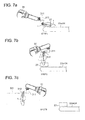
- a pneumatic chucking device 311 is attached to an end of the work mounting arm 31(see FIG.7a and 7b ) .
- the pneumatic chucking device 311 has a pair of chucking pieces 312, 312 movable in directions to access to or depart from each other and a driving device 314 for driving the chucking pieces 312, 312 to access to or depart from each other.
- a depression 313 is formed to each of the chucking pieces 312, 312 on a surface thereof facing each other in order to clamp the ankle part of the work 1.
- the ankle part 8 protruded from the clearance s1 of the V-shaped guide 27 is chucked by the chucking pieces 312, 312, then they are lifted and carried to a work shift over device 32 which is explained later.
- the work 1 is shifted to the clamper 11 by means of the work shift over device 32 to be suspended by the clamper 11.
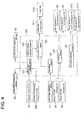
- a controller 120 is provided in the deboning apparatus in order to control total operation of the apparatus.
- the controller 120 performs controlling of transfer speed of the transfer chain 12, controlling of operation of each station, and controlling of other devices in the deboning line.
- a mounting operation program 126 for controlling trajectories of movement and timing of operation of the work mounting arm 31 and movement of the chucking pieces 312, 312.
- Operation signals are sent to the driving device 315 of the work mounting arm 31 and the driving device 314 of the pneumatic chucking device 311 so that the work mounting arm 31 and chucking pieces 312, 312 are operated according to the control programs 126.
- the controller 120 is provided with a calculation means 125 which calculates an optimal transfer speed of the belt conveyor 23 (24) based on the timing detected by the work passing timing detecting sensor 25 (26) and controls the driving device 28(29) of the belt conveyor 23(24) so that the transfer speed of the belt conveyor 23 (24) matches the timing of chucking the work 1 by the work mounting arm 31. That is, the transfer speed of the belt conveyor 23(24) is controlled so that the ankle part 8 of the work 1 is present in the clearance s1 of the V-shaped guides 27 of either of the belt conveyor 23 or 24.
- the work 1 chucked with the chucking pieces 312, 312 of the work mounting arm 31 is suspended by a clamping board 321 as shown in FIG.5 .
- the clamping board 321 consists of a pair of horizontally disposed plates, and between the plates is formed a clearance s3 into which the most narrow part of the ankle part 8 of the work 1 can be inserted for the work 1 to be suspended.
- the work 1 suspending from the claming board is pushed toward a transit clamping board 323, which consists of a pair of plates arranged horizontally between the clamping board 321 and the chain 12 and a clearance s4 of which the width is the same as that of the clearance s3.
- the transit clamping board 323 is transferred in the direction the same as the transfer direction b of the clamper 11 and at the same transfer speed as that of the clamper 11 in synchronism with the clamper 11 by a driving device not shown in the drawing.
- the work 1 hanging from the transit clamping board 323 is pushed out by a pneumatic cylinder 324 toward the the clamper 11 while the transit clamping board 323 is transferred in synchronism with the clamper 11. In this way, the ankle part 8 of the work 1 is inserted into a clearance s5 of the clamper 11 to be suspended therefrom.
- FIG.6 shows a situation of positioning the work 1 on the belt conveyor 23 (24), a state the work 1 is suspended by the clamping board 321, and a state the same is suspended by the clamper 11.
- FIGS.7a to 7c show a proceeding of mounting the work 1 on the belt conveyor 23(24) to the clamping board 321.
- the work 1 is positioned on the belt conveyor 23 (24) so that the ankle part 8 thereof protrudes from the v-shaped guide 27 through the clearance s1 thereof and the protruded ankle part is chucked by the chucking pieces 312, 312 of the work mounting arm 31 at step 1 as shown in FIG.7a . Then the work 1 chucked by the chucking pieces 312,312 is lifted at step 2 as shown in FIG.7b . Then, the work 1 lifted up by means of the work mounting arm 31 is pushed into the clearance s3 between the clamping boards 321 to allow the work 1 to be suspended from the clamping boards 321 at step 3 as shown in FIG.7c . After the work 1 is suspended from the clamping boards 321, the chucking pieces are departed to release clamping of the ankle part of the work 1, then the work mounting arm 31 is retreated.
- the ankle part 8 of the lower femurbone 2 is shaped such that the thickness of the bone increases from the thinnest part toward the end of the ankle part 8 forming a tapered part.
- the work shift over device 32 utilizes this shape of the ankle part and allows the work 1 to be suspended from the work clamping board 321 or clamper 11 by inserting the thinnest part of the ankle part 8 into the clearance s3 in the clamping board 321 of the shift over device 32 or into the clearance s5 in the clamper 11.
- the work 1 When the work 1 is suspended from the chucking pieces 312, 312, clamping board 321, transit clamping board 323, or clamper 11, the work 1 is clamped at a position i thereof where thickness of the tapered part of the ankle part 8 coincides with the clearances s2 ⁇ s5.
- the clearances s2 ⁇ s5 are the same in width
- the position i where the ankle part 8 of the work 1 is engaged with the clamping devices mentioned above is the same for each of the clamping devices. Therefore, by allowing the trajectory of movement of the chucking pieces 312, 312 to come near to the clamping board 321 as shown in FIG.7c , shifting over of the work 1 can be performed smoothly.
- protruded length of the ankle part 8 from the clearance s1 of the V-shaped guide 27 varies depending on individual work 1.
- protrusion of the ankle part from the clearance s1 of the V-shaped guide 27 is larger when a work 1(B) larger in size is positioned by the V-shaped guide 27 than when a work 1(S) smaller in size is positioned by the V-shaped guide 27, and clamped position i of the ankle part 8 of the work 1 varies by a variation of j depending on the size of individual work 1.
- the ankle part 8 can be protruded by the force from the tapered end of the V-shaped guide 27 until a part nearer to the knee joint end side of the lower femurbone 2 is obstructed to pass through the clearance s1 because of its increased thickness. Therefore, the chuck pieces can be brought to a position(chuck position) that is nearer to the knee joint end side than the variation range j of the clamp position i is.
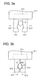
- the chuck pieces 312, 312 are brought to a position that is nearer to the knee joint end side than the variation range j of the clamp position i is in a state the chuck pieces 312, 312 are opened, that is, distance between them are widened as shown in FIG. 3a . Then the distance between the chuck pieces 312, 312 is narrowed to take hold of the ankle 8.
- weight to the work 1 is exerted on the chuck pieces 312, 312, and the work 1 moves down slides along the tapered part of each of the depressions of the chuck pieces 312, 312 until it is stopped at the clamp position i because thickness of the ankle part 8 increases toward the end thereof.
- the distance between the chuck pieces 312, 312 is narrowed by a control signal from the controller 120 based on the mounting operation program 126. That is, when the work 1 is clutched and raised up, and the chucked position comes near the clamp position i due to its weight, the distance between the chuck pieces 312, 312 are narrowed.
- the ankle part 8 is received in the space formed by the depression313, 313 of the chuck pieces 312, 312 and the distance between the chuck pieces is narrowed most.
- the chuck position of the work 1 reaches the clamp position thereof at this time. In this way, the work 1 can be held with certainty by its ankle part 8 by the chuck pieces 312, 312 of the work mounting arm and can be mounted to the clamping board 321 without fail.
- the work 1 is suspended by program-controlling movements of the 6-spindle multi-joint mounting arm 31 and the chuck pieces 312, 312 in the mounting station 30, and the pre-treated work 1 is taken hold of by the chuck pieces 312, 312 and allowed to be suspended from the clamper 11, so mounting operation of the work 1 to the clamper 11 can be automated.
- the pre-treated work 1 transferred on the belt conveyor 23(24) is stopped temporarily by the V-shaped guide 27, the chuck pieces 312, 312 can be engaged with the ankle part 8 with ease.
- the chuck position of the ankle part 8 to clutch by the chuck pieces 312, 312 can be secured at a position adj acent the tapered end of the V-shaped guide 27 and outside the variation range j of the clamp position i, outside in direction to the knee joint side of the lower femurbone 2.
- the chuck pieces 312, 312 are closed, that is distance between them is program-controlled to be narrowed in synchronism with the moving down and sliding movement of the work 1, so the work 1 can be held with certainty in the hollow formed by the depressions 313, 313 of the chuck pieces 312, 312, and occurrence of failure in holding the ankle part 8 and occurrence of damage thereof can be prevented.
- a left and right discrimination device 33 for judging whether the work 1 is a left leg or right leg is provided adj acent to the clamping board 321. After the work 1 is hanged by the clamping board 321 with the fat layer 1a facing toward the clamper 11, the work 1 is stopped once in front of the left and right discrimination device 33 on the way it is pushed by an air cylinder 322 toward the clamper 11. Whether the work 1a is left or right leg is judged.
- construction of the left and right discrimination device33 will be explained with reference to FIGS.8a, 8b and 9 .
- the work 1 stopped in front of the discrimination device 33 is pinched by a pair of measuring arms 331 and a pair of measuring arms 332.
- Driving device of the pair of measuring arms 331 (332) will be explained referring to FIG.9 .
- the measuring arm 331(332) has a rack 333(334) extending perpendicular to the arm 331 (332) .
- Each of the racks 333 and 334 engages with a pinion 335 located between the racks.
- a piston rod 337 of an air cylinder 338 is connected to one of the measuring arms of the pair of the measuring arms 331(332).
- Distance ⁇ ( ⁇ ) between the arms of the pair of arms 331 (332) can be adjusted by actuating the air cylinder 336.
- An encoder 338 is connected to the pinion 335 to detects rotation angles thereof or count the number of rotation thereof.
- the air cylinder 336 is actuated by air which is compressible fluid, the pair of measuring arms 331(332) stops automatically when it clamps the work 1 and receives reaction force of certain strength from the work 1.
- a detection signal of the encoder 338 is sent to a left or right judging means 121 built-in in the controller 120, and the left or right judging means 121 computes the distancea( ⁇ ). Difference has occurred between the thickness of the left and right legs as a result of removing hipbone 4 in the pretreatment station 20.
- FIGS.8a, 8b show a case of right leg (work 1(R)). Distance ⁇ and ⁇ are compared and it is judged that the work 1 is a right leg (work 1 (R) ) when ⁇ > ⁇ and that work 1 is a left leg (work 1 (L)) when ⁇ ⁇ ⁇ .
- the left and right judging device 33 of this construction measurement is performed in a state the work 1 is remaining stationary and left or right of the work 1 is judged by the difference of thickness of the thigh meat between the left and right thereof, so left or right of the work 1 can be judged rightly. Further, the left and right judging device is constructed simply.
- the work 1 After the work 1 is left or right leg part is judged, it is mounted to the clamper 11.
- the clamper 11 is transferred by the driving device 13 in the direction of the arrow b at a constant speed and reaches the initial incision making station 40.
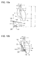
- the clamper 11 stops in front of a work length detection device 41 in the initial incision making station 40. Composition of the work length detection device 41 will be explained with reference to FIGS.10a, 10b and 11 .
- a base bracket 140 is provided facing the work transfer line.
- the base bracket 140 is provided with a proximity switch or limit switch 141 (hereafter referred to as a switch 141) consisted of a switch bar 141a and a contact point 141b.
- a coil spring 142 is provided between the switch bar 141a and the base bracket 140 so that the switch 141 is switched off unless force is applied to the switch bar 141a.
- two supporter pillars 143 are attached to the base bracket to erect upright, and an arm 144 shaped like a rectangular frame is supported by the supporter pillars swingable.
- a side of the rectangular arm 144 opposite to the side thereof supported by the supporter pillars 143 is formed into a pusher bar 145 for pushing away the work 1.
- a counter weight 146 is attached to the arm 144 at the opposite side of the pusher bar 145 so that the arm 144 takes a nearly horizontal attitude unless force is applied to the arm 144.
- length of the arm from its supported point to the pusher bar 145 is longer than horizontal length of the base bracket 140, so the arm 144 can be swung until the pusher bar 145 is below the base bracket 140.
- the lower part thereof is scooped out deeply and the femoral head 3a is exposed.
- the femoral head 3a is not so apart from the lower end part 1b of the work 1. Therefore, if the arm 144 is not provided, there may occur that the switch bar 141a may contacts the end part 1b of the work 1 when the switch bar 141a approaches the work 1 and false operation occurs. Determination of the work length is performed as follows: first the base bracket 140 is advanced in the direction of an arrow k, and the pusher bar 145 forming a forefront part of the arm 144 is brought to a position ahead of the femoral head 3a. Then, the base bracket 140 is lifted up in the direction of an arrow I.
- Distance Y from the clamper 11 to the bottom of the base bracket 140 before the base bracket 140 is moved is a given value, and length W of the work 1, i.e. distance between the clamp position of the ankle part 8 of the work 1 clamped by the clamper 11 and the femoral head 3a, can be determined by subtracting X from Y.
- the switch bar 141a With the work length detection device 41 of this composition, first the pusher bar 145 contacts the lower part 1b of the work 1 and pushes away the lower part 1b, then the switch bar 141a get near to the femoral head 3a, so occurrence of false operation due to occurrence of contact of the switch bar 141a with the lower end part 1b of the work 1 is prevented. Therefore, the switch bar 141a can contact the femoral head 3a without fail and work length W can be determined accurately with certainty.
- the measurement result is used to change over the incision making operation program in the first to third incision making stations 50-70, to determine a start point and end point of knee cap side cutting performed in the last incision making station 80, and to determine a start point and end point of thig-meat scrape-off process performed in the thigh-meat scrape-off station 100.
- the work 1 is passed between a pair of round blade cutters 42 disposed horizontally sandwiching the transfer line 12 to make incision all around at a part of the lower femurbone 2 just under the clamper 11(a part indicated by a line d in FIG.2 ) in order to enable meat scraping in a succeeding process.
- the clamper 11 is rotated when the work 1 is passed between the pair of round blade cutters 42 to make the incision all around the ankle part 8.
- An escape device is provided to allow the round blade cutters to retreat when the round blade cutters receive excessive reaction force from the work 1.
- the bone of the ankle part 8 of the work 1 is prevented from being cut by the round blade cutters by the escape device.
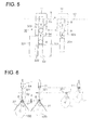
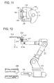
- a cutter tool 513 is attached to an end part 512a of an arm 512.
- the cutter tool 513 consists of a base bracket 516, a swing shaft 514 supported swingablly by the base bracket 516, and a knife-shaped cutter blade 515 attached to the swing shaft 514 at a position offset toward a direction opposite to the advance direction m of the cutter blade 515.
- the cutter blade 515 is a double-edged one having a V-shaped edge in a section perpendicular to the advance direction m of the cutter blade.
- the swing shaft 514 By positioning the swing shaft 514, by the swing of which the cut-in angle n of the cutter blade 515 is determined, nearer to the arm 512 than the cutter blade 515, the point of application of force to drive the cutter blade 515 is advanced toward the cutter blade advance direction m than the actual contact position of the cutter blade 515 to the bone and meat, so the cutter blade 515 can be moved along the surface of the bone.
- the base bracket 516 to which the cutter blade 515 is attached is slidable in directions p perpendicular to both the axial direction of the arm 512 and the advance direction m of the cutter blade 515.
- a slide device 517 for sliding the base bracket 516 comprises a base plate 518 fixed to the arm 512 at its end part 512a to extend in a direction p perpendicular to both the arm 512 and the advance direction m of the cutter blade 515, a linear guide rail 519 mounted on the base plate 518 along its longitudinal direction, and a linear guide bar 521 supported by the base plate 518 at a position above the linear guide rail 519.
- the base bracket 516 is mounted on the linear guide rail 518 and penetrated by the linear guide bar 521 such that the base bracket 516 is slidable along the linear guide rail 513 and linear guide bar 521.
- Coil springs 522 are provided to both sides of the base bracket 516 to surround the linear guide bar 521 so that the base bracket 516 is positioned at the central part of the linear guide bar 521 urged by the elastic force of the coil springs 522.
- the cutter blade 515 is attached to the arm 512 such that the cutter blade is movable in the direction of the arrow p which is perpendicular to the advance direction m of the cutter blade and at the same time such that the cut-in angle n of the cutter blade is variable around the center of the swing shaft 514 by means of an elastic supporting device 523. In this way, the cutter blade 515 can follow the bone smoothly in accordance with variations in thickness and length of the bone.
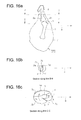
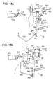
- the cutter tool 513 is operated so that an incision is made from the upper part of the knee joint 5 of the work 1 to the lower end of the femurbone 3 as indicated by e in FIG.2 andFIG.16c.
- the edge part of the cutter blade 515 is allowed to reach the surface of the femurbone 3 such that the side face of cutter blade 515 contacts the surface of the femurbone 3, and the cutter blade 515 is allowed to move down with the middle part thereof moving down along a membrane between a knuckle meat part 7a (shintama in Japanese) and inner thigh meat 7b.
- the detected signal of the encoder 338 of the left and right discrimination device 33 in the mounting station 30 is inputted to the left and right discrimination means 121 of the controller 120, and Judgment whether the work 1 is a left or right leg is performed by the discrimination means 121.
- the lift x of the base bracket 140 measured by the work length detection device 41 in the initial incision making station 40 is inputted to a calculation means 124, which calculates the work length W.
- An incision making operation program most suited for the work 1 to be made incision is selected from among the memorized incision making operation programs 122 by a program selecting means 123 based on these results of judgment and calculation.
- a control signal according to the selected incision making operation program is sent from the controller 120 to a cutting tool driving device 511.
- the cutting tool driving device 511 is attached to a base 510 of the arm 51 for allowing incision making to be performed.
- the cutter tool 513 is driven by means of the cutting tool driving device 511.
- Incision making in the first to third incision making stations is performed by means of the 6-spindle multi-joint arms 51, 61, and 71 composed as mentioned above respectively
- an incision making operation program to control operation trajectory of the cutter blade 515 is selected in accordance with right or left leg and length of the work 1, it is unpreventable that there occurs an error due to difference in size of individual work 1. Fine adjustment to compensate the error is performed by the elastic supporting device 523 which enables two-degree-of-freedom movement of the cutter blade 515, that is, both the adjustment of position of the cutter blade 515 by means of the slide device 517 and adjustment of cut-in angle n of the cutter blade 515 by swinging the cutter blade which is attached to the swing shaft 514.
- FIG.15 An initial position of the cutter blade 515 is set in the incision making operation program at a position the work 1 contacts the surface of the bone q of the work 1. Therefore, as shown in FIG.15 , the cutter blade 515 is first inserted into the meat until it contacts the bone q according to the incision making operation program. An error between the initial position of the bone set in the program and actual position of the bone q due to difference in size of individual work 1 is compensated by allowing the base bracket 516 to slide on the linear guide rail 519 in directions p due to reaction force which the cutter blade 515 receives from the bone q.
- the cutter blade 515 When the end part 512a of the arm 512 moves from the initial position in the advance direction m of the cutter blade according to the incision making operation program, the cutter blade 515 receives reaction force from the surface of the bone q while advancing along the surface of the bone q and the swing shaft 514 rotates. By the rotation of the swing shaft 514, the cut-in angle n of the cutter blade 515 is adjusted to n1 with which the cutter blade 515 advances smoothly along the bone q without biting into the bone.
- the cutter blade 515 advances along the surface of the bone q while compensating the error between the incision making operation program and actual bone due to difference in size of individual work 1, and at the same time can be rotated about the center of the swing shaft 514 in a direction parallel to the surface of the bone q by the reaction force from the bone. As the swing shaft 514 is positioned nearer to the end part 512a of the arm 512 than the cutter blade 515, the cutter blade 515 can be rotated to be parallel to the bone q.
- the cutter blade 515 can advance along the bone without biting into the surface of the bone q and also without departing from the surface of the bone q. Accordingly, incision can be made smoothly along the surface of the bone q in the longitudinal direction thereof smoothly and the cutter blade can advance between the bone q and meat r accurately, so yield of meat can be increased when performing deboning operation.
- the work 1 is rotated by about 45°in clockwise direction when it is a right leg(work 1(R)) and the work 1 is rotated by about 45°in anticlockwise direction when it is a left leg (work 1(L)) by allowing a clamper driving device 15 to operated in accordance with judgment of the left-or-right-of-the work judging means 121.
- the cutter blade 515 inserts into a calf meat part 7d (chimati in Japanese) from the upper part of the lower femurbone 2, the front edge of the cutter blade further advances passing the side of the knee cap 6 and reaches the lower part of the knee joint 5.
- This incision is indicated by a line f in FIG.2 and F IG.16b, 16c .
- the incision line f in FIG.16c rotated by about 90°relative to the incision line f in FIG.16b .
- incision line f appears at a twisted position in FIG.16c .
- incision is made from an upper part of the lower femurbone 2 passing the knee joint 5 along the femurbone 3. This incision is indicated by g in FIG.2 and FIG.16b and 16c .
- an incision making arm is provided for each of the first to third incision making stations separately, it is allowable to provide a single incision making arm to perform incision making of the three kinds when transfer speed of the work 1 is set at low speed.
- composition of a fixing means of the work 1 in the first to third incision making stations will be explained.
- Each of the work fixing means used in each incision making station is the same in construction, and the explanation will be done taking a case in the first incision making station 50 as an example referring to FIG.1 , FIG.17 , FIG.18a, and FIG.18b .
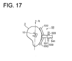
- a back support device 53 for supporting the work 1 from the back surface (fat layer 1a side) thereof is provided at a position facing the incision making arm 51 with the transfer line of the work 1 between.
- the back support device 53 has a backside supporting member 530 consisting of a base member 531 and pairs of support arms 532 of which the arms of each pair extend from the base member 531 toward both sides and slant forward so that the support arms 532 can contact the backside of the work 1.
- a bracket 541 to which the backside supporting member 530 is fixed is supported by a transfer head 535 movable in the transfer direction p of the work 1.
- the transfer head 535 is fitted slidably to a linear guide 536 provided to run parallel to the work transfer direction b so that the backside supporting member 530 is moved smoothly and stably without shaken by the force exerted on the work 1 due to incision making operation.
- To the transfer head 535 is attached an air cylinder 542 of which the piston rod 542a is connected to an end side of a link member 543.
- the link member 543 is supported by a shaft 544 fixed to the transfer head 535 rotatably about the shaft 544.
- the other end of the link member 543 is connected to a middle part of the bracket 541 and the free end of the bracked is connected to an end of a link bar 545.
- the backside supporting member 530 can be moved to approach or depart from the work 1 suspended from the clamper 11 in a double-headed arrow.
- the transfer head 535 is connected to a timing belt 538.
- the transfer head 535 can be transferred in the transfer direction b in synchronism with the clamper 11 by driving(rotating) the timing belt 538 by a servomotor 539.
- the transfer head 535 moves in the transfer direction b at the same speed and in synchronism with the clamper 11.
- the backside supporting member 530 is retreated from the work 1.
- the air cylinder 542 is operated to allow the backside supporting member 530 to approach the work 1 suspended from the clamper 11 to support the work 1 from its backside.
- the back support device 53 is provided separately for each station.
- the air cylinder 542 is actuated to retreat the backside supporting member 530 in each of the back support device.
- the backside support device 53 is moved by the actuation of the servomotor 539 in a direction opposite to the transfer direction b to be returned to its initial position.
- the backside supporting device 53 is composed such that the base member 531 and support arms 532 of the backside supporting member 530 support the back surface of the work 1, the work 1 can be held stable against the force exerting from the cutter blade 515. By holding the work 1 by the backside supporting member 530 in a state the work 1 is slanted, incision making operation by the cutter blade 515 can be facilitated. Further, as the transfer head 535 is driven by the servomotor 539, transfer speed can be controlled, so the servomotor can accommodate arbitral transfer speed of the work 1. Furthermore, the backside supporting member 530 can be returned to its initial position at a speed of two or three timed the transfer speed, because it is in a state of no load. Therefore, it can accommodate speeding up of work transfer speed.
- Programs mentioned below for allowing each of a plurality of incision making arms to make a plurality of kinds of incisions are memorized in the controller 120.
- the controller 120 shown in FIG.4 are set beforehand a plurality of programs to judge right or left leg of the work 1 and determine movement of the cutter tool 513 in accordance of the length of the work 1 as incision making operation programs 122. Two or more incision lines are determined, movement of the cutter blade is determined in correspondence with the determined incision lines, and each of a plurality of incision making arms is allowed to perform incision along a specific incision line.
- a program to be used to perform incision along a specified line is selected from among these programs and a control signal for controlling movement of the cutter tool 513 is sent to the plurality of the incision making arms. In this way, a series of incision making operations are performed by the plurality of incision making arms.
- Incision lines are determined in the embodiment as an example. Incision from a part above the knee joint 5 to the lower end of the femurbone 3 is specified to be performed by the first incision making arm 51 and the arm 51 is operated to make incision indicated by the line e in FIG.1 and FIG.16c . Incision from an upper part of the lower femurbone 2 to part below the knee joint 5 is specified to be performed by the second incision making arm 61 and the arm 61 is operated to make incision indicated by the line f in FIG.16b and 16c .
- Incision from an upper part of the femurbone 3 to a part below the knee joint 5 passing along the side of the knee cap 6 is specified to the third incision making arm 71 and the arm 71 is operated to make incision indicated by the line ginFIG.16b and 16c.
- an appropriate program is selected from among the incision making operation programs 122 by the program selecting means 123 based on right or left leg of the work 1, length of the work 1, and a line of incision specified by the incision making arm 51, and a control signal to the cutting tool driving device 511 of the incision making arm 51 to control movements of the cutter tool 513 and incision making arm 51.
- an appropriate program is selected from among the incision making operation programs 122 by the program selecting means 123 based on right or left leg of the work 1, length of the work 1, and a line of incision specified to the incision making arm 61 or 71, and a control signal is sent to the cutting tool driving device of the incision making arm 61 or 71 to control movements of the cutting tool of the incision making arm 61 or 71 and the incision making arm 61 or 71.
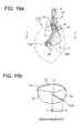
- FIG.19a is a longitudinal section of the work 1 (R) with the hipbone removed as is in the case of FIG.16a and FIG.19b is a section along a line D-D in FIG.19a .
- fine-hatched parts x indicate the incision along the surface of the bones and a coarse-hatched part y indicates the incision in the meat part 7.
- Reference numeral 3aa is a head and 3ab is a greater trochanter of the femurbone 3.
- the incision line e in FIG.2 or FIG.16c consists of a incision line e1 and e2 shown in FIG. 19a .
- FIG.19a first the incision is made along the line e1 in the direction sown by an arrow.
- the incision line e1 serves to give a clue to facilitate intrusion of the cutter blade 515 between the membrane of the knuckle meat 7a and the membrane of the inner thigh meat 7b when cutting out with the incision line e2 the boundary between the knuckle meat 7a and inner thigh meat 7b. Therefore, the incision along the line e1 is performed in first.
- Incision along the line e1 is started by making cut-in by the cutter blade 515 at the tibia 2a of the lower femurbone 2, the cutter blade advances to the knee joint part 5 while disconnecting the membrane at the corner part of the tibia 2a.
- the cutter blade 515 is intruded between the membranes at the boundary of knuckle meat 7a and inner thigh meat 7b until the front edge part of the cutter blade 515 reach the surface of the femurbone 3 to start incision along the line e2 continuing to the incision along the line e1.
- the boundary between the knuckle meat 7a and inner thigh meat 7b is cut with the middle part of the cutter blade 515.
- the cutter blade moves to the side and end part of the greater trochanter 3ab to end the incision along the line e2.
- the incision line f consists of an incision line2 f1 and f2.
- incision along the line f1 is performed.
- the start point f1 (s) of the incision line f1 is determined at a position on the right side face of the end part of the ankle part 8 of the tibia 2a.
- the cutter blade 515 makes a cut-in at the start point f1 (s) and advances along the right side face of the tibia 2a to the side end part of the knee joint 5.
- depth of intrusion of the cutter blade 515 is such that the front edge of the cutter blade 515 reaches a middle part of the thickness (diameter) of the tibia as shown by a hatched part x2 in FIG.20b so that the cutter blade advances while cutting off the connection of the membrane of the calf meat 7d at the corner part of the tibia 2a.
- the cutter blade 515 is advanced from the start point f1 (s) to an end point f1 (e) near the knee joint part 5.
- the calf meat 7d can be scraped off easily.
- incision along an incision line f2 is performed.
- This incision line f2 starts from a start point f2 (s) positioned at the middle part of the tibia 2a, and the cutter blade 515 is inserted between the tibia 2a and fibula 2b.
- the cutter blade 515 is advanced along the side face of the tibia 2a toward the knee joint part 5, and then the cutter blade 515 is advanced to the connecting part of the tibia 2a and fibula 2b as shown by a hatched part x3 in FIG.20c .
- the cutter blade further goes through while cutting the root part of the fibula 2b to separate the fibula 2b from the tibia 2a. In this way, ligaments and tendons concentrating in the knee joint part 5 can be cut off from the knee joint 5.
- the cutter blade 515 further advances along the incision line f2 along the femurbone 3 near the knee joint 5 to reach the femur head 3aa and further advances along the side face of the knee cap 6.
- the incision along the incision line f1 and f2 the biomedical tissue such as muscle, tendon, and ligament adhering to the lower femurbone 2 and knee joint part 5 can be removed easily. Therefore, meat scraping in the succeeding lower-thigh-meat scrape-off station 90 and thigh-meat scrape-off station 100 can be facilitated.
- the work holding device 55 comprises an air cylinder 552 attached to the frame 551, a work holding bar 553, and a link bar for connecting the air cylinder 552 and work holding bar 553.
- the work holding bar 553 fixed to an end of the ling bar 554 and this fixed part is supported rotatably by a bracket 555 fixed to the frame 551.
- the other end of the link bar 554 is connected to a piston rod 552a of the air cylinder 552.
- the work holding device 55 is used when a cross hatched part z of the incision line f2 in FIG.20c .
- the incision is made in the rear side of the work 1 relative to its front side which faces the incision making arm 61, so the work 1 is raised from the back face side thereof. Accurate incision can not be made when the work 1 is raised up, so the work holding bar 553 is used.
- the air cylinder 552 is actuated and the work holding bar 553 is brought to touch on and push the front face of the work 1.
- the incision line g in this station starts from a cut-in at a start point g(s) at the end of the ankle part of the tibia 2a.
- the cutter blade 515 is advances from the start point g(s) along the side face of the tibia 2a toward the knee joint part 5 and further advances along the femurbone 3.
- depth of intrusion of the cutter blade 515 when it advances along the tibia 2a is such that the front edge of the cutter blade 515 reaches a middle part of the thickness (diameter) of the tibia and meat between the tibia 2a and fibula 2b is not cut as shown by a hatched part x4 in FIG.21b .
- the meat between the tibia 2a and fibula 2d is cut, the meat between the tibia and fibula separates off from the shank meat 7e, and the meat between the tibia and fibula remains on the bones in the succeeding meat scrape-off process.
- the cutter blade 515 is intruded in the knee joint part 5 to such a depth that incision is made over the total width along the surface profile of the bones of the knee joint part 5.
- surfaces of the bones near the knee joint part 5 depict a curve like a letter 3, and many tendons for connecting muscle to the bones are present at three points of 5a, 5b, and 5c near the knee joint part, so it is intended to cut the tendons near this part with certainty.
- the cutter blade advances to the femur head 3aa along the side of femurbone 3, passing through the top part of the femurbone 3aa and ending the incision g at the ending point g(e).
- the incision along the incision line g must be performed after the incision along the incision line e is performed. If the incision g is performed without performing the incision e, the cutter blade 515 cut off a right part(in FIG.22b ) of the inner thigh meat 7b when the incision g is made along the side face of the femurbone as shown in FIG.22b shown for comparison. Therefore, in the embodiment, the incision e is performed first to make incision between the knuckle meat 7a and inner thigh meat 7b as shown in FIG.16c , then the incision g is performed. In this way, the incision g can be performed without cutting off the right part of the inner thigh meat 7b.
- incisions are made by using the 6-spindle multi-joint arms 51, 61, and 71 driven under incision operation programs in previous steps of the steps performed in the lower-thigh-meat scrape-off station 90 and thigh-meat scrape-off station 100, so incision making process can be automated. Further, as incision can be made corresponding with complicated three dimensional curves of the bones of the work 1, meat remaining on the bones can be decreased resulting in increased yield of meat.
- Three of 6-spindle multi-joint arms are arranged along the work transfer line and each of three kinds of incision making operation is assigned to be performed by each of the three incision making arms, time for making all of the incisions can be reduced as compared with a case all of the incisions are made by a single incision making arm. Therefore, work transfer speed can be increased, and continuous deboning operation of the work 1 without stoppage is made possible, resulting in increased efficiency of deboning operation.
- Judgment of right or left leg of the work 1 and determination of the work length are performed in the early step of the deboning process, a most suited program is selected for each of the incision making arms from among six kinds of incision operation programs based on the results of the judgment and measurement, and each of the 6-spindle multi-joint arms is actuated under the selected program. Therefore, the cutter blade 515 can be moved to match individual work 1 with high accuracy.
- the cutter blade 515 is supported movable in directions p perpendicular to its advance direction m and swingable by means of the elastic supporting device 523, so an error of the trajectory of the cutter blade 515 due to difference in size of individual work 1 can be compensated by the elastic supporting device 523. Therefore the cutter blade 515 can be moved accurately along the surfaces of the bones, and yield of meat can be increased spectacularly.
- incision making operation in the first to third incision making stations 50, 60, and 70 in this order that is, by making incision along the incision line g after incision along the incision line e is made, knuckle meat 7a, inner thigh meat 7b, and outer thigh meat 7c surrounding the shaft of the femurbone can be separated from the bone without hurting them.
- deboning can be performed without decreasing commercial value of the meat.
- deboning operation in the succeeding processes can be facilitated.
- the work 1 is transferred to the last incision making station 80a to perform a latter incision making operation.
- a round blade cutter device 81a for right leg and a round blade cutter device 81b for left leg are positioned facing each other with the transfer chain 12 between.
- incision is made with a round blade cutter along the side face of the knee cap in the longitudinal direction. Its incision line is indicated by a line h in FIG.2 and FIG.16c .
- a cutter drive changeover device 83 allows the round blade cutter device 81a for right leg or round blade cutter device 81b for left leg to be driven based on the result of judgment of the left or right judging means 121.
- the result of judgment of the left or right judging means 121 is sent also to the clamper driving device 15.
- the clamper driving device 15 By operation of the clamper driving device 15, the front face of the work 1(R) is allowed to face the round blade cutter device 81a for right leg and incision is made by the round blade cutter 81a when the work 1 is a right leg, and the front face of the work 1(L) is allowed to face the round blade cutter device 81b for left leg and incision is made by the round blade cutter 81b when the work 1 is a left leg.
- the work 1 is transferred to the lower-thigh-meat scrape-off station 90 and thigh-meat scrape-off station 100 in the attitude as is. This gives that the work 1 is transferred always with its knee cap 6 facing upstream of its transfer direction irrespective of its being right or left leg in the stations 80, 90, and 100.
- FIG.23a a columnar support 813 and a screw bar 814 are installed upright near the transfer line of the work 1.
- a cutter unit including a round blade cutter 822 and a casing 821 in which a driving device of the round blade cutter 822 is built-in is supported by a base bracket 820 via a bracket 823 fixed to the casing 821.
- a piston rod 824a is connected to the bracket 823.
- At this connecting part is connected rotatably an end of a link bar 825 via a shaft 826.
- the other end of the link bar 825 is supported rotatably by a shaft 827 fixed to the base bracket.
- the cutter unit can be rotated about the center of the shaft 827 by actuating the air cylinder 824, and blade tilt angle of the round blade cutter 822 which is perpendicular to the center axis t of the cutter unit can be changed relative to the work 1.
- a guide member 816 having an arm part 817, the guide member being supported by the columnar support 813 to be slidable along it, the arm part 817 being engaged with the screw bar 814 by means of ball screw engagement.
- a servomotor 818 At the top of the screw bar 814 is provided a servomotor 818.
- the base bracket 820 can be moved up and down by actuating the servomotor 818.
- Height position of the base bracket 820 can be varied down to the millimeter. Height position of starting incision making with the round blade cutter 822 and incision making stroke of the cutter are changed in accordance with the work length detected by the work length detection device 41. As the incision starting position can be adjusted down to the millimeter and a starting position beat suited to individual work 1 can be selected, biting of the round blade cutter into the bone does not occur.
- the round blade cutter 822 can be move up and down smoothly at stable speed thanks to the ball screw engagement. Ending position of incision making can be adjusted so that yield of meat is increased.
- the blade angle relative to the work 1 can be changed while moving down, and incision along the curved side face of the knee cap can be made. In this way, yield of meat around the knee cap can be increased.
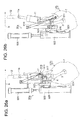
- scraping of meat around the lower femurbone is performed in the lower-thigh-meat scrape-off station 90.
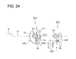
- the procedure will be explained taking the right leg work 1 (R) for example with reference to FIG.24 .
- the last incision making operation is performed in an attitude that the front face of the right leg work 1 (R) faces the round cutter device 81a for right leg and the front face of left leg work 1 (L) faces the round cutter device 81b for left leg, and the work 1 is transferred to the lower-thigh-meat scrape-off station 90 in the same attitude.
- an interosseous scraper 911 having a protruded part 912 to be inserted between the tibia and fibula advances toward the transfer line 12 of the work 1(R) and the protruded part 912 is inserted between the tibia 2a and fibula 2b.
- the work 1 is lifted up in an oblique direction as the work 1 (R) is moved and meat around the lower femurbone is scraped off.
- a scraper 931 and a swing scraper 932 advances toward the transfer line 12 of the work 1(R) from the opposite side to touch the work 1(R).
- the platy swing scraper 932 can be swung about a support shaft 932a in up and down directions and elastic force to push the swing scraper downward is applied by a spring not shown in the drawing.
- the interosseous scraper 911 is allowed to touch the back-side side face of the tibia 2a(part u in FIG.24 ) and meat around this part is scraped off with certainty
- the scraper 931 and the swing scraper 932 are allowed to touch the outer periphery of the fibula 2b (part v in FIG.24 ) and meat around this part is scraped off with certainty.
- lower-thigh-meat scrape-off devices 91a and 93a for right leg and lower-thigh-meat scrape-off devices 91b and 93b for left leg are provided facing each others with the transfer line 12 between.
- right leg work 1(R) scraping-off of meat around the lower femurbone is performed by the first and second lower thigh-meat scrape-off devices 91a and 93a for right leg
- left leg work 1(L) scraping-off of meat around the lower femurbone is performed by the first and second lower-thigh-meat scrape-off devices 91b and 93b for left leg.
- result of judgment of right or left leg of the work 1 by the left or right judging means 121 is sent to a scraper drive changeover device 92, which select the lower-thigh-meat scrape-off device for right leg or that for left leg to be driven based on the judgment.
- the first lower-thigh-meat scrape-off device 91a for right leg is shown.
- the first lower-thigh-meat scrape-off device 91b for left-leg not shown in the drawings and the lower-thigh-meat scrape-off device 91a for right-leg are positioned symmetrically to each other about the transfer line 12.
- the platy interosseous scraper 911 has a protruded part 912 being shaped like a sickle able to be inserted between the tibia 2a and fibula 2b and attached to a base bracket 910 swingable about a vertical shaft 913.
- a coil spring 914 Between the interosseous scraper 911 and the base bracket 910 is provided a coil spring 914, which supports the interosseous scraper 911 elastically and enable swing motion thereof about the vertical shaft 913.
- a slider 915 which is supported slidably along a guide rail 921 fixed to a frame 920.
- the base bracket 910 can be moved in lateral horizontal directions to approach or retreat from the transfer line 12 by actuating an air cylinder 923, of which a piston rod 923a being connected to the base bracket 910, attached to the frame 920.
- the frame 920 has a slider 925, which is engaged with a guide rail 924 fixed to a columnar support 922 installed upright, and the frame 920 can be moved up and down by actuating an air cylinder 926.
- a scraper unit 916 including the interosseous scraper 911 and coil spring 914 is supported by the base bracket 910 swingably about a horizontal shaft 917 fixed to the base bracket 910. To the base bracket 910 is attached an air cylinder 918 which applies force to the scraper unit 916 to keep it in horizontal attitude.
- the air cylinder 923 is actuated to push the base bracket 910 toward the transfer line 12 so that the interosseous scraper 911 is positioned under the transfer line 12.
- the interosseous scraper 911 is retained horizontal by the air cylinder 918, and when the work 1 reaches the interosseous scraper 911, the scraper 911 is inserted between the tibia 2a and fibula 2b.
- Meat scraping with the interosseous scraper 911 starts by moving of the clamper in the transfer direction b, and at the same time , by meat scraping is performed by allowing the frame 920 to move down by means of the air cylinder 926.
- Meat between the tibia 2a and fibula 2b, particularly meat around the part u in FIG.24 can be scraped off with the interoseous scraper 911.
- Air pressure of the air cylinder 918 is adjusted so that interosseous scraper 911 is swung to depart from the work 1 when force larger than a threshold value exerts on the scraper 911.
- Timing of end of the meat scraping can be obtained by calculating transfer position of the clamper 11 based on the work length detected by the work length detection device 41, so it is set such that the piston rod of the air cylinder 918 is advanced at a timing of "meat scraping end position + ⁇ ". Even if the interosseous scraper 911 is pinched in the clearance between the tibia and fibula, the scraper 911 can be extracted from the clearance by the actuation of the air cylinder 918 at this timing.
- FIG.27 shows a case when a clearance s6 is in the recess of the clamper 11 between the tibia 2a and the bottom of the recess, (b) shows a case when the tibia 2a is large in width and the leading edge 912 of the interosseous scraper 911 is out of the clearance between the tibia 2a and fibula 2b, and (c) shows a case when there is no clearance between the tibia 2a and the bottom of the recess of the clamper 11 but the leading edge 912 of the interosseous scraper 911 is not completely out of the clearance between the tibia 2a and fibula 2b.
- a platy scraper 931 is fixed to a base bracket 930 at a position to face the transfer line 12.
- a platy swing scraper 932 To the scraper 931 is attached a platy swing scraper 932 via a horizontal shaft 933 swingably about the horizontal shaft 933.
- a coil spring 947 is set between the swing scraper 932 and scraper 931 so that the swing scraper 932 is energized downward by the spring 947.
- a slider of the base bracket 930 is engaged with a guide rail 941 of the frame 940 so that the base bracket can slide relative to the frame 940.
- a piston rod 942a of an air cylinder 942 attached to the frame 940 is connected to the base bracket 930.
- the base bracket 930 can be advanced toward or retreated from the transfer line 12 by actuating the air cylinder 942.
- a columnar support 943 is installed upright, and a slider 944 of the frame 940 is engaged with a guide rail 945 of the columnar support 943 so that the frame 948 can be slid vertically.
- the frame 940 is moved vertically by actuating an air cylinder 946 of which the piston rod is connected to the frame 940.
- the base bracket 930 is advanced toward the right leg work 1 (R) experienced meat scraping process by the first lower-thigh-meat scrape-off device 91a for right-leg to allow the scraper 931 and swing scraper 932 to touch the work 1(R).
- the clamper 11 is moving in the transfer direction b at constant speed, the work 1(R) is pulled by the clamper 11 and meat scraping by the scrapers begins.
- the air cylinder 946 is actuated and the frame 940 is moved down, so meat scraping is finished while the work 1(R) is transferred a short distance as shown in FIG.30 .
- meat scraping can be finished while the work 1 is transferred a short distance by moving down the frame 940, space saving is possible, and in parallel, as the inclination of the work 1 is not so large, area of scraping as represented by a1 in FIG.30 is small. Therefore, meat scraping force per unit area can be increased, and in parallel, as the scrapers touch the bone directly, effect of meat scraping can be increased. Therefore, yield of meat can be increased. Further, as the swing scraper 932 pushes the fibula part from above by the elastic force of the coil spring 947, meat scraping effect thereof can be increased.
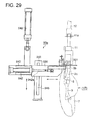
- thigh meat is scraped off in the thigh-meat scrape-off station 100.
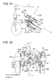
- a thigh-meat scrape-off device 101 is provided in the thigh-meat scrape-off station 100. Construction of the thigh-meat scrape-off device 101 will be explained with reference to FIGS.31 to 35 .
- a meat separator 1012 and round blade cutters 1031 are disposed on a lower fixed frame 1011 such that they are slanted downward in the work transfer direction.
- the thigh-meat scrape-off device 101 is disposed to straddle the work transfer line 12.
- the lower fixed frame 1011 is placed straddling the work transfer line 12 and the meat separator 1012 is disposed at the middle part of the lower frame 1011.
- the meat separator 1012 has a concave portion 1013 opened toward upstream of the transfer direction b by an opening 1014, the width of the opening 1014 being such that the upper part of the knee joint of the work 1 can pass into the concave portion 1013, the concave portion 1013 being shaped to have a V-shaped bottom 1015 so that the femurbone 3 is centered at the bottom 1015 in the concave portion 1013 so that the femoral head 3a does not interfere with the edge of the concave portion 1013.
- a chucking device 1020 for chucking the ankle part 8 of the work 1 inserted into the concave portion 1013 of the meat separator 1012 to prevent disengagement of the ankle part 8 form the meat separator.
- the chucking device 1020 is composed of a pair of swing plates 1021 attached to the underside face of the meat separator1012, an air cylinder 1022, piston rod of the air cylinder 1022, and a link bars 1024 for connecting the piston rod 1023 to the swing plate 1021.
- Each of the swing plates 1021 swings about a supporting point 1025 in directions a double-headed arrow e1 when the cylinder rod 1023 moves in directions of a double-headed arrow d1 by actuating the air cylinder 1022, thus the opening 1014 of the concave portion 1013 can be opened and closed.
- the meat separator 1012 just above the meat separator 1012 are disposed two pairs of round blade cutters 1012, by which is made circumferential incision at a middle part between the underside face of the knee cap 6 and the femoral head 3a on the way of meat scraping and is performed cutting-off of meat under the femoral head 3a for last separation of meat.
- Cutting operation of the round blade cutter 1031 is performed based on the result of measurement of work length detection device 41.
- the round blade cutter 31 is attached to an upper frame 1041 via L-shaped link bar 1042.
- L-shaped link bar 1042 (see FIG.33 ) attached to an upper frame 1041 rotatably via a shaft 1043.
- An end of the L-shaped link 1042 is connected to a connecting member 1045 which can be moved up and down by means of a ball screw 1044 on top of which is connected a servomotor 1046 for rotating the ball screw 1044.
- a casing 1032 having a driving device for driving the round blade cutter 1031 is connected to a bracket 1034 via a plate 1033.
- the bracket 1034 is connected rotatably to a connecting member 1036 via a horizontal shaft 1035.
- the connecting member 1036 is connected to a swing arm 1037.
- the awing arm 1037 which is connected to a base bracket 1030 rotatably about a shaft 1038.
- the L-shaped link bar 1042 is connected to the base bracket 1030 via a link 1047.
- each air cylinder 1039 for each of the pair of round blade cutters 1031.
- Apiston rod of each air cylinder 1039 is connected to each swing arm 1037, so each round blade cutter 1031 is supported elastically in horizontal direction via the air cylinder 1039 which serves as a shock absorber.
- each round blade cutter 1031 moves in the direction of an arrow b1 and the force exerted on the round blade cutter is alleviated.
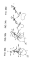
- FIG.36 the work 1 transferred in the direction b intrudes into the concave portion 1013 of the meat separator 1012 disposed at a height position corresponding to the position just above the knee joint part 5 of the work 1 transferring along the transfer line 12.
- the air cylinder is actuated and the pair of swing plates 1021 rotates to close the opening 1014 of the concave portion 1013 of the meat separator, thus the work 1 is chucked.
- the chucked work 1 continues to be transferred horizontally in the direction b, so the work 1 is pulled obliquely upward and the femurbone is pressed to the V-shaped bottom 1015 of concave portion 1013 due to the weight of the work 1 and transfer of the clamp 11.
- scraping off of meat can be finished by a single scraping action.
- scraping off of meat from the femurbone is possible by making a single incision along the femurbone 3(the third incision making process).
- meat by cutting muscles, tendons, and ligaments adhering to the circumference of the bones by performing at least two circumferential incision at a middle part between the underside face of the knee cap 6 and the femoral head 3a on the way of meat scraping, meat can be removed with high yield rate.
- the meat part 7 is separated from the femurbone 3 and the separated meat is fallen down on a conveyor 102 disposed under the thigh-meat scrape-off device 101.
- the meat part 7 fallen on the conveyor 102 is transferred in the direction of an arrow c.
- meat scraping process can be simplified dramatically and processing time can be decreased, so processing capacity can be increased.
- many combinations of meat separator, cutter, and work lifting means were necessary for meat separation processing, whereas with the embodiment, the same processing can be performed only with a combination of meat separator and cutter and work transfer device. Therefore, serious cost reduction and space saving can be achieved according to the invention.
- anteroposterior movement of the round blade cutter 1031 is achieved by rotating the servomotor 1046 in such a way that the rotation of the servomotor is converted via a bal screw device to vertical linear motion which is converted to the anteroposterior movement of the round blade cutter via link mechanism, so speed, timing, and operating position of the anteroposterior movement of the round blade cutter 1031 can be controlled accurately. Therefore, occurrence of break in blade edge of the round blade cutter 1013 is prevented resulting in increased durability thereof.
- the round blade cutter 1031 When the round blade cutter 1031 make incision into the meat, its blade edge contacts the bone for a certain time(0.5-1.0 second). As the work 1 transfers at a constant speed, position of contact of the blade edge to the bone of the work 1 varies while the work 1 transfers if the cutter is supported solidly without flexibility, and force perpendicular to the cutter is exerted on the blade edge, which may break the blade edge.
- the round blade cutter 1031 is supported rotatable about the horizontal shaft 1035, so the round blade cutter 1031 can be swung about the horizontal shaft 1035 pulled by the transferring the work 1 in a state the blade edge is touching the bone.
- a horizontal line N shows a position where the blade edge of the round blade cutter 1031 has just touched the bone and a line M shows a position where the round blade cutter 1031 has swung upward.
- the cutter When the bone of the work 1 depart from the blade edge of the round blade cutter 1031, the cutter returns to its initial position by its own gravity.
- the plate 1033 contacts the underside face of the connecting member 1036 so that the round blade cutter 1031 is kept in horizontal attitude and can not swing downward. Further, as the round blade cutter 1031 is supported pneumatically via the air cylinder 1039, it can be retreated from the work 1 when excessive force exerts on the work 1 and occurrence of break in the blade edge of the cutter can be prevented.
- the bones hanging from the clamper 11 after meat is scraped off in the thigh-meat scrape-off station 100 are removed from the clamper 11 in the bone discharging station 110 and falls down on a conveyor 111 to be transferred in the direction of arrow c. ,
- deboning process of a pig thigh part can be automated, operators can be released from hard work, yield of meat can be increased, speed up of deboning line is made possible, and processing efficiency can be improved. Furthermore, by removing pig thigh meat without impairment, its commodity value is not degraded. For example, by setting work transfer speed at7 seconds per one processing station, deboning of 500 leg parts per an hour is made possible.
- deboning of a leg part of a slaughtered domestic animal can be automated, processing capacity can be increased, and yield of meat can be increased without degrading commodity value of the meat.
Abstract


Description
- The invention relates to a method and apparatus for automating incision-making process made at a previous step before entering a deboning step of a leg part of a slaughtered domestic animal by use of a multi-axial multi-joint arm and an operation program for allowing the apparatus to carry out the incision-making.
- In dissection and de-boning operation of a slaughtered domestic animal that is a fairly heavy object, operators have been forced to experience heavy physical labor. Therefore, labor saving by automatization and improvement in yield rate of meat has been studied.
Inpatent literature 1 is disclosed a semi-automated de-boning machine for carrying out de-boning of a pig thigh and a method of de-boning by use of the machine. In the machine pig thighs experience a pretreatment process, meat scrape-off process for scraping off meat adhering to the lower femurbone, and meat scrape-off process for scraping off meat adhering to the femurbone while the pig thighs are transferred in a state they are suspended with their ankles clamped with clampers attached to a transfer chain. - All the processes are carried out in a state the pig thighs are hung in midair so that influence of their own weight in the processing is suppressed to a minimum, operations on a chopping board is eliminated so that adhesion of bacteria via the chopping board is prevented and sanitary deboning operation is carried out, and manual processing is limited to the pretreatment process at the first step and the succeeding de-boning processes are automated. Thus, streamlining and reduction in labor power in de-boning operation were achieved.
- In the pretreatment process, the
hipbone 4 including the hipbone and tailbone are removed and incisions are made to the meat along the lower femurbone (including tibia and fibula) and femurbone by an operator while the pig thigh is transferred hanging from the clamper. In this succeeding automated processes, incisions are made with a cutter around the lower thigh and thigh of the pig thigh hanging from the clamper while scraping off the meat adhering to bones with a meat scraper. By this, biomedical tissue such as muscle, tendon, and ligament adhering to the bones are cut, and meat is separated from the bones stepwise. These incisions are made with a cutter to cut biomedical tissue surrounding the bones at determined positions in longitudinal direction by rotating the pig thigh. - In
patent literature 2 is disclosed a method and apparatus for automating a process of making incision into the thigh meat of poultry performed as a preprocessing in de-boning process of a poultry thigh. A thigh holding and an incision making devices are provided in an incision making station provided on a transfer route of a buffer conveyor, and the incision is made by the incision making device in a state the poultry thigh is held by the thigh holding device in a prescribed attitude. -
- Patent literature 1: Japanese laid-Open Patent Application No.
2000-106818 - Patent literature 2: Japanese laid-Open Patent Application No.
2001-149001 - With the de-boning apparatus disclosed in the
patent literature 1, incisions to meat along the lower femurbone (including tibia and fibula) and femurbone are carried out manually, so, degree of automation is no so high. It is necessary, when making incision to meat along the lower femurbones and femurbone in longitudinal direction thereof, that the cutter is manipulated to runs along the surface of the bone without biting into the bones in order to achieve high yield of meat. However, automation of the incision making operation, which must be performed along bone shape while properly controlling depth of incision, has been difficult because the bones have complicated 3-dimensional shapes including bend and twist. - In the incision making apparatus disclosed in the
patent literature 2, although incision-making operation is automated, the cutter blade for making incision to meat is directed in a constant direction, and there is room for improvement to cope with the complicated 3-dimensional shape of the bones.
In addition, it is necessary to provide a retention device in order to hold and keep the poultry thigh in such an accurate attitude that incision can be made properly. Furthermore, time is needed to hold and keep the attitude of the poultry thigh, so it is necessitated to stop transferring of the poultry thigh in order to fix the poultry thigh to the retention device. - The present invention was made in light of problems in prior art and aims to automate incision-making process to thigh meat while accommodated to complicated 3-dimentional profile and make it possible to increase line speed of de-boning line, thereby increasing operation efficiency.
Further, the invention aims to perform incision-making operation that enables de-boning operation of a thigh without damaging the thigh meat so that commodity value of the separated thigh meat is not decreased. - To attain the objects, the present invention proposed a method of making incision to a leg part of a slaughtered domestic animal in longitudinal direction using a multi-spindle multi-joint arm having at a forefront end thereof a cuter blade, wherein incision making processes include a first incision making process for making incision between a knuckle meat and an inner thigh meat around a femurbone, a second incision making process for cutting biomedical tissues around a lower femurbone and knee cap, and a third incision making process for making incision into a connecting part of the inner thigh meat to the femurbone to separate the inner thigh meat from the femurbone, whereby the third incision making process is performed after the first incision making process.
- According to the method of the invention, incision making operation is automated by using a multi-spindle multi-j oint arm having at its forefront part a cutter blade. The cutter blade can be moved along the complicated 3-dimentional surfaces of bones to make incision between the bones and meat by using the multi-spindle multi j oint arm, thereby decreasing meat remained on the bones, resulting in increased yield of meat.
- As the incision to separate the knuckle meat and inner thigh meat around the femurbone is made and then the connecting part of the inner thigh meat and the femurbone is cut to separate the knuckle meat from the femurbone, the knuckle meat and inner thigh meat can be separated from the femurbone without damaging the meat. Therefore, commodity value of the knuckle meat and inner thigh meat is not degraded.
- It is preferable that trajectories of movement of the cutting blade are controlled by program-controlling the multi-spindle multi-joint arm under a program in which a trajectory of the cutter blade for each incision making and sequence of making incisions are set. The three incisions along surfaces of bones are made accurately in the determined order.
- All of the first to third incision making operations may be performed by a single multi-spindle multi-joint arm or may be performed by a plurality of multi-spindle multi-joint arms. For example, it is preferable to perform the three incision making operation by three multi-spindle multi-joint arms. When deboning is performed while transferring the leg part continuously, it is more advantageous to share the first to third incision making operations among the three multi-spindle multi-joint arms arranged along the transfer line than to perform the three incision making operations by a single multi-spindle multi-joint arm in order to increase transfer speed of the leg part. By using three multi-spindle multi-joint arms, efficiency of deboning the leg part can be increased.
- It is preferable that the incisions are made by allowing the cutter blade to move from the upper side downward while the leg part is transferred in a state it is hanged from a clamper with its ankle part held by the clamper and one of both side faces perpendicular to the transfer direction of the leg part is supported so that the leg part is not moved by force exerted on the leg part by the cutter blade.
By composing such that the transfer line for making incision continues to the transfer line to scrape off meat from bones, deboning operation including incision making operation can be performed while transferring the leg part at a constant speed continuously without stoppage, and deboning processing capacity can be increased. - It is preferable that at least one of the incisions is made by configuring the cutter blade to move from the upper side downward while the leg part is transferred in a state it is hanging from a clamper with its ankle part held by the clamper and both side faces perpendicular to a transfer direction of the leg part are supported so that the leg part is not moved by force exerted on the leg part by the cutter blade. Ligaments and tendons are adhering strongly to bones in the upper part of the femoral head and it is necessary to make incision near the femoral head to move the cutter blade to move around the femoral head and further around the side surface of the knee cap. Therefore, it is preferable to support the leg part from both side faces thereof perpendicular to the transfer direction of the leg part.
- It is preferable that a plurality of kinds of incision making operation programs are provided to correspond to right leg part or left leg part as well as a variety of length of the leg part, judgment whether the leg part is a right one or left one and determination of length of the leg part are performed before the incisions are made, and an incision making operation program most suited for making incision to the leg part is selected from among the incision making operation programs based on the judgment and the determination. By this, an incision making operation program most suited for individual leg part is selected to make incision. Therefore, high yield rate of meat can be obtained regardless of right or left leg part and long or short of length thereof.
- As an apparatus for practicing the method of the invention is proposed an apparatus for making incision to a slaughtered domestic animal, having a multi-spindle multi-joint arm or arms, in which apparatus incisions are made in longitudinal direction of a leg part of the slaughtered domestic animal before deboning processing is performed, comprising; one or a plurality of multi-spindle multi-joint arms disposed along a deboning work line, each of the arms having a cutter blade at its forefront end and being controlled under an incision making operation program, whereby incision making operation consisting of a first incision making process for making incision between a knuckle meat and an inner thigh meat around a femurbone, a second incision making process for cutting biomedical tissues around a lower femurbone and knee cap, and a third incision making process for making incision into a connecting part of the inner thigh meat to the femurbone to separate the inner thigh meat from the femurbone, is performed in upstream of a deboning line by controlling the arm or arms.
- The method of the invention can be implemented with the apparatus. With the apparatus, one or a plurality of multi-spindle multi-joint arms are arranged along a deboning operation line and incision making operation is performed by controlling the multi-spindle multi-joint arm or arms having cutter blade attached to the forefront part thereof under a incision making operation program or programs to make the first to third incisions.
By the apparatus, the cutter blade can be advanced to follow the surfaces of the bones and deboning can be performed with increased yield of meat without damaging knuckle meat and inner thigh meat. - It is preferable that the cutter blade is supported by an elastic supporting device attached to the forefront end of the multi-spindle multi-joint arm such that the cutter blade is slidable in direction perpendicular to advance direction of the cutter blade and swingable about a shaft perpendicular to the side direction and advance direction of the cutter blade so that difference between a trajectory of movement of the cutter blade programmed in the incision making operation program and actual trajectory to be followed by the cutter blade due to difference in size of individual leg part is compensated by the elastic supporting of the cutter blade to allow the cutter blade to follow 3-dimentional profiles of surfaces of bones of the leg part.
- By supporting the cutter blade via the elastic supporting device, the cutter blade can be moved to follow the complicated three dimensional profile of surfaces of bones of the leg part compensating slight difference in profile of individual leg part. Therefore, deboning of leg part is made possible with decreased meat remaining on the bones even if there is considerable degree of individual difference in each leg part.
- An incision making operation program according to the present invention is configured to allow one or plurality of multi-spindle multi-joint arms to be operated to perform the incision making processes recited above.
The incision making processes according to the invention can be performed under the program to achieve action and effect of the method of the invention. - The incision making operation program of the invention may be created such that the first to third incisions are performed by a single multi-spindle multi-joint arm, or such that the first to third incisions are performed by a plurality of multi-spindle multi-joint arms. For example, it is preferable that the program allows three multi-spindle multi-joint arms arranged along a transfer line of leg part to perform the first to third incisions sequentially. By creating the program such that the first to third incision making operations are shared among the three multi-spindle multi-joint arms, incision making operation can be performed fast and accurately, yield of meat is increased, and incision making processing capacity can be increased.
- According to the invention, in a method of making incision using a multi-spindle multi-joint arm or arms equipped with a cutter blade at its forefront end part along longitudinal direction of a leg part of a slaughtered domestic animal in a preceding step of deboning operation, incision making operation can be automated and incision along complicated three dimensional profile of the bones of the leg part is made possible by performing a first incision making process for making incision between a knuckle meat and an inner thigh meat around a femurbone; a second incision making process for cutting biomedical tissues around a lower femurbone and knee cap; and a third incision making process for making incision into a connecting part of the inner thigh meat to the femurbone to separate the inner thigh meat from the femurbone, and performing the third incision making process after the first incision making process. By the automation of the incision making operation, labor force is saved, incision making process capacity is increase, and yield of meat is increased.
- Furthermore, among the meat around the femurbone, knuckle meat is separated from inner thigh meat first in the first incision making process, then the inner thigh meat is separated from the femurbone in the third incision making process, so each meat part can be separated without experiencing damage, as a result deboning is made possible without degrading commodity value of meat separated from the bone.
- The method of the invention can be practiced by composing an apparatus, having multi-spindle multi-joint arm or arms, in which incisions are made in longitudinal direction of a leg part of the slaughtered domestic animal before deboning process such that; it comprises one or a plurality of multi-spindle multi-joint arms disposed along a deboning work line, each of the arms having a cutter blade at its forefront end and being controlled under an incision making operation program, whereby incision making operation consisting of a first incision making process for making incision between a knuckle meat and an inner thigh meat around a femurbone, a second incision making process for cutting biomedical tissues around a lower femurbone and knee cap, and a third incision making process for making incision into a connecting part of the inner thigh meat to the femurbone to separate the inner thigh meat from the femurbone, is performed in upstream of a deboning line by controlling the arm or arms.
- The incision making operation program of the invention is made such that it allows the incision making operation of the invention to be performed by one or a plurality of multi-spindle multi-joint arms, and the cutter blade of the multi-spindle multi-joint arm is moved along the bones of the leg part following three dimensional profile of the surfaces of the bones, therefore deboning of the leg part can be automated, yield of meat is increased, and incision making processing capacity can be increased.
-
-
FIG.1 is a plan view showing overall construction of the deboning apparatus of an embodiment of the present invention. -
FIG.2 is a representation of all processing steps performed by the deboning apparatus. -
FIG.3a and FIG.3b are a plan view of a chuck part of a multi-spindle multi-joint arm, showing when the chuck is opened and closed, respectively. -
FIG.4 is a block diagram of the control system of the deboning apparatus. -
FIG.5 is a plan view showing the work shifting device of the deboning apparatus. -
FIG.6 is a representation for explaining catch-and-hang step of the pig thigh in the deboning process. -
FIGS.7a to 7c are drawings showing procedure of catch-and-hang step of the pig thigh. -
FIG. 8a is an elevation view for explaining the discrimination device for distinguishing the right leg of the pig from the left one, andFIG.8b is a section along a line A-A inFIG.8a . -
FIG.9 is a drawing for explaining the driving device for driving the discrimination device shown inFIG.8a and 8b . -
FIG.10a is an elevation view of the work length detection device showing a state before the device is engaged, andFIG.10b shows when the device is engaged. -
FIG.11 is a plan view of the work length detection device. -
FIG.12 is a side view of the multi-spindle multi-joint arm for making incision. -
FIG.13 is plan view of an elastic supporting device of a cutter blade. -
FIG.14 is a front view of the elastic supporting device ofFIG.13 . -
FIG.15 is a drawing for explaining movement of the cutter blade when incision is made. -
FIG.16a is a front view of a right pig thigh,FIG.16b is a section along a line B-B inFIG.16a, and FIG,16c is a section along a line C-C inFIG.16a . -
FIG.17 is a plan view of the back surface supporter. -
FIG.18a is a front view of the front surface and back surface supporting device when the device is not engaged, andFIG.18b is when the device is engaged. -
FIGS.19a and 19b are drawings showing incision making positions in the first incision making process,FIG.19a being front view of the pig leg part andFIG.19b being a section along a line D-D inFIG.19a . -
FIGS.20a∼c are drawings showing incision making positions in the second incision making process,FIG.20a being front view of the pig leg part,FIG.20b being a view in the direction of an arrow E inFIG.20a, and FIG.20c being view in the direction of an arrow F inFIG.20b . -
FIGS.21a and 21b are drawings showing incision making positions in the third incision making process,FIG.21a being front view of the pig leg part, andFIG.21 being a view in the direction of an arrow G inFIG.21a . -
FIG.22a is a sectional view along a line H-H inFIG.21a, and FIG.22b is a view as inFIG.22a of a comparative example to explain the necessity that the first incision e must be performed before performing the third incision g. -
FIG.23a is a front view of the last incision-making device, andFIG.23b is an enlarged view of a part I of the pig thigh inFIG.23a . -
FIG.24 is a drawing for explaining the meat scrape-off process for scraping off meat adhering to the lower femurbone. -
FIG.25 is a plan view of the first lower-thigh-meat scrape-off device used in the first step of the lower-thigh-meat scrape-off process. -
FIGS.26a and 26b are a front view of the first lower-thigh-meat scrape-off device ofFIG.25 , respectively. -
FIG.27 is a drawing for explaining positional relation between the interosseous scraper of the first lower-thigh- meat scrape-off device and thework 1. -
FIG.28 is a plan view of the second lower-thigh-meat scrape-off device used in the second step of the lower-thigh-meat scrape-off process. -
FIG.29 is a front view of the second lower-thigh-meat scrape-off device ofFIG.28 . -
FIG.30 is a drawing for explaining meat scrape-off process performed by the second lower-thigh-meat scrape-off device ofFIG.28 . -
FIG.31 is a side view of the thigh-meat scrape-off device. -
FIG.32 is a view in the direction of an arrow J inFIG.31 . -
FIG.33 is a view in the direction of an arrow K inFIG.31 . -
FIG. 34 is a plan view of the chucking device of the thigh-meat scrape-off device with the meat separator depicted with a dashed double-dotted line on the chucking device. -
FIG.35 is a partial enlarged view ofFIG.33 . -
FIGS.36a∼d are drawings for explaining deboning process performed by the thigh-meat scrape-off device. - Preferred embodiment of the present invention will now be detailed with reference to the accompanied drawings. It is intended, however, that unless particularly specified, dimensions, materials, relative positions and so forth of the constituent parts in the embodiment shall be interpreted as illustrative only not as limitative of the scope of the present invention.
- An embodiment of the invention applied to pig femurbone removing apparatus will be explained with reference to
FIGS.1∼36 .FIG.1 is a plan view showing overall construction of the deboning apparatus of an embodiment of the present invention, andFIG.2 is a representation of all processing steps performed by the deboning apparatus.
Referring toFIG.2 , a pig leg part 1(hereafter referred to as a work 1) includes a lower femurbone 2 (including tibia and fibula), afemurbone 3, ahipbone 4, aknee cap 6 positioned at a front part of the kneejoint part 5 of thefemurbone 3, andmeat 7 surrounding these bones. As shown inFIG.16b and 16c , a meat part surrounding thelower femurbone 2 consists of acalf meat part 7d (chimaki in Japanese) andshank 7e, and a meat part surrounding the femurbone consists of aknuckle meat part 7a (shintama in Japanese),inner thigh meat 7b, andouter thigh meat 7c of which the outer surface is covered with afat layer 1a. - First, the
hipbone 4 is removed by an operator manually in apretreatment station 20. Then, anankle part 8 of thework 1 deprived of the hipbone 4(hereafter thework 1 deprived of thehipbone 4 is also referred to as work 1) is mounted on a transfer line of the deboning apparatus at awork mounting station 30 using a multi-spindlemulti-joint arm 31. The work 1 (leg part) is clamped at its ankle to aclamper 11 fixed to atransfer chain 12 of the transfer line at random, regardless whether it is a right or left leg part. In this state, automated processes are carried out at stations from an initialincision making station 40 to abone discharging station 110. - In
FIG.1 , thetransfer chain 12 is installed horizontally and driven by a drivingdevice 13 for the clamper to be circulated at a constant speed. As shown inFIG.5 , theclamper 11 has a recession for receiving theankle 8 of thework 1 and is fixed to the chain at an equal spacing. Theclamper 11 is transferred along the circulation route formed by thetransfer chain 12 horizontally at a constant speed while suspending thework 1. Thework 1 is suspended in such an attitude that thefat layer 1a thereof is directed to the inner side of the circulation route formed by thetransfer chain 12 during it is transferred from the initialre-incision making station 40 to a lastincision making station 80. - Discrimination of right or left leg is done in a mounting
station 30 as mentioned later. A device for rotating theclamper 11 and afulcrum 11a (seeFIG.26 and 36) for allowing theclamper 11 to tilt toward the transfer direction b are provided. The clamper rotating device is used in a firstincision making station 50 to a thirdincision making station 70, and the tilting device is used in a lower-thigh-meat scrape-off station 90 for scraping off meat from the lower femurbone and in a thigh-meat scrape-off station 100 for scraping off meat from the femurbone. - In the
pretreatment station 20 are arrangedbelt conveyors belt conveyors hipbone 4 from each of theworks 1 as pretreatment in thisstation 20.Belt conveyors belt conveyors Sensors works 1 are provided respectively at each entrance of thebelt conveyors - The deboning line downstream the
line threshold 14. The operators P turn theworks 1 deprived of theirhipbones 4 so that theirankle parts 8 face toward left in the direction of the arrow a with theirfat layers 1a contacting the surfaces of each of theconveyors ankle part 8 is directed exactly in the direction of the longitudinal center line of the belt. - The
works 1 laid on thebelt conveyor belt conveyor belt conveyors 23 and 24is provided a V-letter shapedguide 27. The V-shapedguide 27 consists of a pair ofrectangular plates guide plates 27a are disposed such that their rectangular surfaces are vertical and the lower end of the vertical plates does not contact the surface of the belt. - Between the
guide plates 27a arranged in V-shape exists a clearance s1 through which theankle part 8 can pass. When thework 1 deprived of thehipbone 4 reaches the V-shapedguide 27, thework 1 is pushed against the inclined surfaces of the V-shapedguide 27 due to the traveling of the belt conveyor 23 (24) in the direction of the arrow a. Theankle part 8 enters the clearance s1 by the pushing force and protrudes from the clearance s1. This state is shown inFIG.6 . - The mounting
station 30 is provided downstream of the belt conveyor23(24), and a 6-vertical-spindle multi-joint arm 31 for mounting thework 1 on the deboning line is provided in the station. As shown inFIG.3 , apneumatic chucking device 311 is attached to an end of the work mounting arm 31(seeFIG.7a and 7b ) . Thepneumatic chucking device 311 has a pair of chuckingpieces driving device 314 for driving the chuckingpieces - A
depression 313 is formed to each of the chuckingpieces work 1. Theankle part 8 protruded from the clearance s1 of the V-shapedguide 27 is chucked by the chuckingpieces device 32 which is explained later. Thework 1 is shifted to theclamper 11 by means of the work shift overdevice 32 to be suspended by theclamper 11. - As shown in
FIG.4 , acontroller 120 is provided in the deboning apparatus in order to control total operation of the apparatus. Thecontroller 120 performs controlling of transfer speed of thetransfer chain 12, controlling of operation of each station, and controlling of other devices in the deboning line. In thecontroller 120 is memorized a mountingoperation program 126 for controlling trajectories of movement and timing of operation of thework mounting arm 31 and movement of the chuckingpieces work mounting arm 31 and thedriving device 314 of thepneumatic chucking device 311 so that thework mounting arm 31 and chuckingpieces - The
controller 120 is provided with a calculation means 125 which calculates an optimal transfer speed of the belt conveyor 23 (24) based on the timing detected by the work passing timing detecting sensor 25 (26) and controls the driving device 28(29) of the belt conveyor 23(24) so that the transfer speed of the belt conveyor 23 (24) matches the timing of chucking thework 1 by thework mounting arm 31.
That is, the transfer speed of the belt conveyor 23(24) is controlled so that theankle part 8 of thework 1 is present in the clearance s1 of the V-shapedguides 27 of either of thebelt conveyor - Next, composition of the work shift over
device 32 will be explained referring toFIG.5 . Thework 1 chucked with the chuckingpieces work mounting arm 31 is suspended by a clampingboard 321 as shown inFIG.5 . The clamping board 321consists of a pair of horizontally disposed plates, and between the plates is formed a clearance s3 into which the most narrow part of theankle part 8 of thework 1 can be inserted for thework 1 to be suspended. - The
work 1 suspending from the claming board is pushed toward atransit clamping board 323, which consists of a pair of plates arranged horizontally between the clampingboard 321 and thechain 12 and a clearance s4 of which the width is the same as that of the clearance s3. Thetransit clamping board 323 is transferred in the direction the same as the transfer direction b of theclamper 11 and at the same transfer speed as that of theclamper 11 in synchronism with theclamper 11 by a driving device not shown in the drawing. - The
work 1 hanging from thetransit clamping board 323 is pushed out by apneumatic cylinder 324 toward the theclamper 11 while thetransit clamping board 323 is transferred in synchronism with theclamper 11. In this way, theankle part 8 of thework 1 is inserted into a clearance s5 of theclamper 11 to be suspended therefrom. - Distance s2 between the bottoms of the
depressions pieces FIG.3b is the same as clearance s3 in the clampingboard 321, clearance s4 in thetransit clamping board 323, and clearance s5 in the clamper 11.Thetransit clamper board 323 is returned to its initial position adjacent the clampingboard 321 by means of a drive device not shown in the drawing after thework 1 is shifted over to theclamper 11. - Next, proceeding of mounting the
work 1 on the belt conveyor 23 (24) to the clampingboard 321 by means of thework mounting arm 31 will be explained referring toFIG.6 andFIG.7 .FIG.6 shows a situation of positioning thework 1 on the belt conveyor 23 (24), a state thework 1 is suspended by the clampingboard 321, and a state the same is suspended by theclamper 11.FIGS.7a to 7c show a proceeding of mounting thework 1 on the belt conveyor 23(24) to the clampingboard 321. - The
work 1 is positioned on the belt conveyor 23 (24) so that theankle part 8 thereof protrudes from the v-shapedguide 27 through the clearance s1 thereof and the protruded ankle part is chucked by the chuckingpieces work mounting arm 31 atstep 1 as shown inFIG.7a . Then thework 1 chucked by the chucking pieces 312,312 is lifted atstep 2 as shown inFIG.7b . Then, thework 1 lifted up by means of thework mounting arm 31 is pushed into the clearance s3 between the clampingboards 321 to allow thework 1 to be suspended from the clampingboards 321 atstep 3 as shown inFIG.7c . After thework 1 is suspended from the clampingboards 321, the chucking pieces are departed to release clamping of the ankle part of thework 1, then thework mounting arm 31 is retreated. - As can be seen in
FIG.6 , theankle part 8 of thelower femurbone 2 is shaped such that the thickness of the bone increases from the thinnest part toward the end of theankle part 8 forming a tapered part. The work shift overdevice 32 utilizes this shape of the ankle part and allows thework 1 to be suspended from thework clamping board 321 orclamper 11 by inserting the thinnest part of theankle part 8 into the clearance s3 in the clampingboard 321 of the shift overdevice 32 or into the clearance s5 in theclamper 11. - When the
work 1 is suspended from the chuckingpieces board 321,transit clamping board 323, orclamper 11, thework 1 is clamped at a position i thereof where thickness of the tapered part of theankle part 8 coincides with the clearances s2∼s5. As the clearances s2∼s5 are the same in width, the position i where theankle part 8 of thework 1 is engaged with the clamping devices mentioned above is the same for each of the clamping devices. Therefore, by allowing the trajectory of movement of the chuckingpieces board 321 as shown inFIG.7c , shifting over of thework 1 can be performed smoothly. - On the other hand, when positioning of the
work 1 is performed by the V-shapedguide 27 disposed at the transfer end of the belt conveyor 23 (24), protruded length of theankle part 8 from the clearance s1 of the V-shapedguide 27 varies depending onindividual work 1. As shown inFIG.6 , protrusion of the ankle part from the clearance s1 of the V-shapedguide 27 is larger when a work 1(B) larger in size is positioned by the V-shapedguide 27 than when a work 1(S) smaller in size is positioned by the V-shapedguide 27, and clamped position i of theankle part 8 of thework 1 varies by a variation of j depending on the size ofindividual work 1. - Force of pushing the
work 1 to allow theankle part 8 to protrude from the tapered end of the V-shapedguide 27 through the clearance s1 is generated by the transferal movement of the belt conveyor 23(24), that is, by friction between thework 1 which is stopped on the belt barred by the V-shapedguide 27 and the surface of the transferring belt. Theankle part 8 can be protruded by the force from the tapered end of the V-shapedguide 27 until a part nearer to the knee joint end side of thelower femurbone 2 is obstructed to pass through the clearance s1 because of its increased thickness. Therefore, the chuck pieces can be brought to a position(chuck position) that is nearer to the knee joint end side than the variation range j of the clamp position i is. - The
chuck pieces chuck pieces FIG. 3a . Then the distance between thechuck pieces ankle 8. When thework 1 is lifted, weight to thework 1 is exerted on thechuck pieces work 1 moves down slides along the tapered part of each of the depressions of thechuck pieces ankle part 8 increases toward the end thereof. - When the chucked position comes near to the clamp position i, the distance between the
chuck pieces controller 120 based on the mountingoperation program 126. That is, when thework 1 is clutched and raised up, and the chucked position comes near the clamp position i due to its weight, the distance between thechuck pieces work 1 is lifted up by thework mounting arm 31 and the total weight of thework 1 is exerted on thechuck pieces ankle part 8 is received in the space formed by the depression313, 313 of thechuck pieces work 1 reaches the clamp position thereof at this time. In this way, thework 1 can be held with certainty by itsankle part 8 by thechuck pieces board 321 without fail. - The
work 1 is suspended by program-controlling movements of the 6-spindlemulti-joint mounting arm 31 and thechuck pieces station 30, and thepre-treated work 1 is taken hold of by thechuck pieces clamper 11, so mounting operation of thework 1 to theclamper 11 can be automated. As thepre-treated work 1 transferred on the belt conveyor 23(24) is stopped temporarily by the V-shapedguide 27, thechuck pieces ankle part 8 with ease. - As the
ankle part 8 is protruded from the tapered end of the V-shapedguide 27 through the clearance s1 sufficiently due to the friction force exerting on thework 1 on the belt conveyor 23(24) due to transfer of the belt in the direction of the arrow a, the chuck position of theankle part 8 to clutch by thechuck pieces guide 27 and outside the variation range j of the clamp position i, outside in direction to the knee joint side of thelower femurbone 2.
By allowing thework 1 to move down by its own gravity while sliding along the taper parts of the depressions of thechuck pieces chuck pieces work 1, so thework 1 can be held with certainty in the hollow formed by thedepressions chuck pieces ankle part 8 and occurrence of damage thereof can be prevented. - By allowing the movement trace of the
chuck pieces board 321, shifting over of the work lean be performed smoothly and without fail.
As the belt conveyor 21(22) is also used for pre-treatment in thepre-treatment station 20, construction of the pre-treatment station20can be simplified. - A left and
right discrimination device 33 for judging whether thework 1 is a left leg or right leg is provided adj acent to the clampingboard 321. After thework 1 is hanged by the clampingboard 321 with thefat layer 1a facing toward theclamper 11, thework 1 is stopped once in front of the left andright discrimination device 33 on the way it is pushed by anair cylinder 322 toward theclamper 11. Whether thework 1a is left or right leg is judged. Hereinafter, construction of the left and right discrimination device33 will be explained with reference toFIGS.8a, 8b and 9 . - Referring to
FIGS.8a and 8b , thework 1 stopped in front of thediscrimination device 33 is pinched by a pair of measuringarms 331 and a pair of measuringarms 332. Driving device of the pair of measuring arms 331 (332) will be explained referring toFIG.9 . InFIG.9 , the measuring arm 331(332) has a rack 333(334) extending perpendicular to the arm 331 (332) . Each of theracks pinion 335 located between the racks. - A
piston rod 337 of anair cylinder 338 is connected to one of the measuring arms of the pair of the measuring arms 331(332). Distance α(β) between the arms of the pair of arms 331 (332) can be adjusted by actuating theair cylinder 336. Anencoder 338 is connected to thepinion 335 to detects rotation angles thereof or count the number of rotation thereof. As theair cylinder 336 is actuated by air which is compressible fluid, the pair of measuring arms 331(332) stops automatically when it clamps thework 1 and receives reaction force of certain strength from thework 1. - A detection signal of the
encoder 338 is sent to a left or right judging means 121 built-in in thecontroller 120, and the left or right judging means 121 computes the distancea(β).
Difference has occurred between the thickness of the left and right legs as a result of removinghipbone 4 in thepretreatment station 20.FIGS.8a, 8b show a case of right leg (work 1(R)).
Distance α and β are compared and it is judged that thework 1 is a right leg (work 1 (R) ) when α > β and thatwork 1 is a left leg (work 1 (L)) when α < β. By the left and right judgingdevice 33 of this construction, measurement is performed in a state thework 1 is remaining stationary and left or right of thework 1 is judged by the difference of thickness of the thigh meat between the left and right thereof, so left or right of thework 1 can be judged rightly. Further, the left and right judging device is constructed simply. - After the
work 1 is left or right leg part is judged, it is mounted to theclamper 11. Theclamper 11 is transferred by the drivingdevice 13 in the direction of the arrow b at a constant speed and reaches the initialincision making station 40. Theclamper 11 stops in front of a worklength detection device 41 in the initialincision making station 40. Composition of the worklength detection device 41 will be explained with reference toFIGS.10a, 10b and11 . - In
FIGS.10a, 10b , and11 , abase bracket 140 is provided facing the work transfer line. Thebase bracket 140 is provided with a proximity switch or limit switch 141 (hereafter referred to as a switch 141) consisted of aswitch bar 141a and acontact point 141b. Acoil spring 142 is provided between theswitch bar 141a and thebase bracket 140 so that theswitch 141 is switched off unless force is applied to theswitch bar 141a. When thebase bracket 140 is moved up and theswitch bar 141a pushed down by thework 1 to be brought to contact thecontact point 141b, theswitch 141 is switched on, and the lift X of the base bracket is determined upon switching on of theswitch 141. - As shown in
FIG.11 , twosupporter pillars 143 are attached to the base bracket to erect upright, and anarm 144 shaped like a rectangular frame is supported by the supporter pillars swingable. A side of therectangular arm 144 opposite to the side thereof supported by thesupporter pillars 143 is formed into apusher bar 145 for pushing away the work 1.Acounter weight 146 is attached to thearm 144 at the opposite side of thepusher bar 145 so that thearm 144 takes a nearly horizontal attitude unless force is applied to thearm 144. As shown inFIG. 11 , length of the arm from its supported point to thepusher bar 145 is longer than horizontal length of thebase bracket 140, so thearm 144 can be swung until thepusher bar 145 is below thebase bracket 140. - As the
work 1 is deprived of thehipbone 4, the lower part thereof is scooped out deeply and thefemoral head 3a is exposed. Thefemoral head 3a is not so apart from thelower end part 1b of thework 1. Therefore, if thearm 144 is not provided, there may occur that theswitch bar 141a may contacts theend part 1b of thework 1 when theswitch bar 141a approaches thework 1 and false operation occurs. Determination of the work length is performed as follows: first thebase bracket 140 is advanced in the direction of an arrow k, and thepusher bar 145 forming a forefront part of thearm 144 is brought to a position ahead of thefemoral head 3a. Then, thebase bracket 140 is lifted up in the direction of an arrow I. - When the
base bracket 140 is advanced and lifted toward thework 1, thepusher bar 145 touches against the lower end part of thework 1 and pushes it away, so occurrence of contact of theswitch bar 141a with thelower end part 1b of thework 1 is prevented. Thearm 144 swings downward and rotates upon receiving reaction force from thework 1, and theswitch bar 141a contacts thefemoral head 3a and is pushed down as thebase bracket 140 further moves up until theswitch bar 141a contact thecontact point 141b. This state is shown inFIG.10b .
Lift X of thebase bracket 140 at the time theswitch bar 141a contacts the contact point and theswitch 141 is switched on is determined. Distance Y from theclamper 11 to the bottom of thebase bracket 140 before thebase bracket 140 is moved is a given value, and length W of thework 1, i.e. distance between the clamp position of theankle part 8 of thework 1 clamped by theclamper 11 and thefemoral head 3a, can be determined by subtracting X from Y. - With the work
length detection device 41 of this composition, first thepusher bar 145 contacts thelower part 1b of thework 1 and pushes away thelower part 1b, then theswitch bar 141a get near to thefemoral head 3a, so occurrence of false operation due to occurrence of contact of theswitch bar 141a with thelower end part 1b of thework 1 is prevented. Therefore, theswitch bar 141a can contact thefemoral head 3a without fail and work length W can be determined accurately with certainty.
The measurement result is used to change over the incision making operation program in the first to third incision making stations 50-70, to determine a start point and end point of knee cap side cutting performed in the lastincision making station 80, and to determine a start point and end point of thig-meat scrape-off process performed in the thigh-meat scrape-off station 100. - Next, in the initial
incision making station 40, thework 1 is passed between a pair ofround blade cutters 42 disposed horizontally sandwiching thetransfer line 12 to make incision all around at a part of thelower femurbone 2 just under the clamper 11(a part indicated by a line d inFIG.2 ) in order to enable meat scraping in a succeeding process. Theclamper 11 is rotated when thework 1 is passed between the pair ofround blade cutters 42 to make the incision all around theankle part 8. An escape device is provided to allow the round blade cutters to retreat when the round blade cutters receive excessive reaction force from thework 1. The bone of theankle part 8 of thework 1 is prevented from being cut by the round blade cutters by the escape device. - Then, longitudinal incisions are made. Three kinds of incisions are made in each of the first
incision making station 50, secondincision making station 60, and thirdincision making station 70. Vertical 6-spindlemulti-joint arms 51, 62, and 71 for making incision, each having a cutter blade at its forefront part and each being of the same construction, are arranged along thetransfer line 12. Construction of the incision-making arm will be explained taking the 6-spindle multi-joint arm 51 as an example with reference toFIGS.12 to 14 . - In
FIGS.12∼14 , acutter tool 513 is attached to anend part 512a of anarm 512. Thecutter tool 513 consists of abase bracket 516, aswing shaft 514 supported swingablly by thebase bracket 516, and a knife-shapedcutter blade 515 attached to theswing shaft 514 at a position offset toward a direction opposite to the advance direction m of thecutter blade 515. Thecutter blade 515 is a double-edged one having a V-shaped edge in a section perpendicular to the advance direction m of the cutter blade.
By positioning theswing shaft 514, by the swing of which the cut-in angle n of thecutter blade 515 is determined, nearer to thearm 512 than thecutter blade 515, the point of application of force to drive thecutter blade 515 is advanced toward the cutter blade advance direction m than the actual contact position of thecutter blade 515 to the bone and meat, so thecutter blade 515 can be moved along the surface of the bone. - The
base bracket 516 to which thecutter blade 515 is attached is slidable in directions p perpendicular to both the axial direction of thearm 512 and the advance direction m of thecutter blade 515. Aslide device 517 for sliding thebase bracket 516 comprises abase plate 518 fixed to thearm 512 at itsend part 512a to extend in a direction p perpendicular to both thearm 512 and the advance direction m of thecutter blade 515, alinear guide rail 519 mounted on thebase plate 518 along its longitudinal direction, and alinear guide bar 521 supported by thebase plate 518 at a position above thelinear guide rail 519. Thebase bracket 516 is mounted on thelinear guide rail 518 and penetrated by thelinear guide bar 521 such that thebase bracket 516 is slidable along thelinear guide rail 513 andlinear guide bar 521. - Coil springs 522 are provided to both sides of the
base bracket 516 to surround thelinear guide bar 521 so that thebase bracket 516 is positioned at the central part of thelinear guide bar 521 urged by the elastic force of the coil springs 522.
As just described, thecutter blade 515 is attached to thearm 512 such that the cutter blade is movable in the direction of the arrow p which is perpendicular to the advance direction m of the cutter blade and at the same time such that the cut-in angle n of the cutter blade is variable around the center of theswing shaft 514 by means of an elastic supportingdevice 523.
In this way, thecutter blade 515 can follow the bone smoothly in accordance with variations in thickness and length of the bone. - In the first
incision making station 50, thecutter tool 513 is operated so that an incision is made from the upper part of theknee joint 5 of thework 1 to the lower end of thefemurbone 3 as indicated by e inFIG.2 andFIG.16c. On this occasion, the edge part of thecutter blade 515 is allowed to reach the surface of thefemurbone 3 such that the side face ofcutter blade 515 contacts the surface of thefemurbone 3, and thecutter blade 515 is allowed to move down with the middle part thereof moving down along a membrane between aknuckle meat part 7a (shintama in Japanese) andinner thigh meat 7b. - If the
cutter blade 515 inserts into meat part too deep from the surface of the femurbone, it will hurt the meat. Therefore, operation of thecutter blade 515 in the incision making process is controlled by thecontroller 120 shown inFIG.4 . In thecontroller 120 are memorized 6 kinds of incision makingoperation programs 122 based on whether thework 1 is a right or left leg and whether the length thereof is long or middle or short. - The detected signal of the
encoder 338 of the left andright discrimination device 33 in the mountingstation 30 is inputted to the left and right discrimination means 121 of thecontroller 120, and Judgment whether thework 1 is a left or right leg is performed by the discrimination means 121. The lift x of thebase bracket 140 measured by the worklength detection device 41 in the initialincision making station 40 is inputted to a calculation means 124, which calculates the work length W. An incision making operation program most suited for thework 1 to be made incision is selected from among the memorized incision makingoperation programs 122 by a program selecting means 123 based on these results of judgment and calculation. - A control signal according to the selected incision making operation program is sent from the
controller 120 to a cuttingtool driving device 511. As shown inFIG.12 , the cuttingtool driving device 511 is attached to abase 510 of thearm 51 for allowing incision making to be performed. Thecutter tool 513 is driven by means of the cuttingtool driving device 511. Incision making in the first to third incision making stations is performed by means of the 6-spindlemulti-joint arms 51, 61, and 71 composed as mentioned above respectively - Although an incision making operation program to control operation trajectory of the
cutter blade 515 is selected in accordance with right or left leg and length of thework 1, it is unpreventable that there occurs an error due to difference in size ofindividual work 1. Fine adjustment to compensate the error is performed by the elastic supportingdevice 523 which enables two-degree-of-freedom movement of thecutter blade 515, that is, both the adjustment of position of thecutter blade 515 by means of theslide device 517 and adjustment of cut-in angle n of thecutter blade 515 by swinging the cutter blade which is attached to theswing shaft 514. - Incision making operation of the
cutter blade 515 will be explained referring toFIG.15 . An initial position of thecutter blade 515 is set in the incision making operation program at a position thework 1 contacts the surface of the bone q of thework 1. Therefore, as shown inFIG.15 , thecutter blade 515 is first inserted into the meat until it contacts the bone q according to the incision making operation program. An error between the initial position of the bone set in the program and actual position of the bone q due to difference in size ofindividual work 1 is compensated by allowing thebase bracket 516 to slide on thelinear guide rail 519 in directions p due to reaction force which thecutter blade 515 receives from the bone q. - When the
end part 512a of thearm 512 moves from the initial position in the advance direction m of the cutter blade according to the incision making operation program, thecutter blade 515 receives reaction force from the surface of the bone q while advancing along the surface of the bone q and theswing shaft 514 rotates. By the rotation of theswing shaft 514, the cut-in angle n of thecutter blade 515 is adjusted to n1 with which thecutter blade 515 advances smoothly along the bone q without biting into the bone.
Thecutter blade 515 advances along the surface of the bone q while compensating the error between the incision making operation program and actual bone due to difference in size ofindividual work 1, and at the same time can be rotated about the center of theswing shaft 514 in a direction parallel to the surface of the bone q by the reaction force from the bone. As theswing shaft 514 is positioned nearer to theend part 512a of thearm 512 than thecutter blade 515, thecutter blade 515 can be rotated to be parallel to the bone q. - Therefore, the
cutter blade 515 can advance along the bone without biting into the surface of the bone q and also without departing from the surface of the bone q. Accordingly, incision can be made smoothly along the surface of the bone q in the longitudinal direction thereof smoothly and the cutter blade can advance between the bone q and meat r accurately, so yield of meat can be increased when performing deboning operation. - In the first to third
incision making stations 50 to 70, in order to make it easy for thecutter blade 515 of theincision making arm 51 to reach the position to perform incision, thework 1 is rotated by about 45°in clockwise direction when it is a right leg(work 1(R)) and thework 1 is rotated by about 45°in anticlockwise direction when it is a left leg (work 1(L)) by allowing aclamper driving device 15 to operated in accordance with judgment of the left-or-right-of-the work judging means 121. - In the second
incision making station 60, such an incision is made that thecutter blade 515 inserts into acalf meat part 7d (chimati in Japanese) from the upper part of thelower femurbone 2, the front edge of the cutter blade further advances passing the side of theknee cap 6 and reaches the lower part of theknee joint 5. This incision is indicated by a line f inFIG.2 and FIG.16b, 16c . The incision line f inFIG.16c rotated by about 90°relative to the incision line f inFIG.16b . This is because thelower femurbone 2 is twisted relative to thefemurbone 3 and the incision line f runs along the bones, so the incision line f appears at a twisted position inFIG.16c .
In the thirdincision making station 70, incision is made from an upper part of thelower femurbone 2 passing theknee joint 5 along thefemurbone 3. This incision is indicated by g inFIG.2 andFIG.16b and 16c . - Although an incision making arm is provided for each of the first to third incision making stations separately, it is allowable to provide a single incision making arm to perform incision making of the three kinds when transfer speed of the
work 1 is set at low speed. - Next, composition of a fixing means of the
work 1 in the first to third incision making stations will be explained. Each of the work fixing means used in each incision making station is the same in construction, and the explanation will be done taking a case in the firstincision making station 50 as an example referring toFIG.1 ,FIG.17 ,FIG.18a, and FIG.18b . InFIG.1 , aback support device 53 for supporting thework 1 from the back surface (fat layer 1a side) thereof is provided at a position facing theincision making arm 51 with the transfer line of thework 1 between. InFIG.17 ,18a, and 18b , theback support device 53 has abackside supporting member 530 consisting of abase member 531 and pairs ofsupport arms 532 of which the arms of each pair extend from thebase member 531 toward both sides and slant forward so that thesupport arms 532 can contact the backside of thework 1. - A
bracket 541 to which thebackside supporting member 530 is fixed is supported by atransfer head 535 movable in the transfer direction p of the work 1.Thetransfer head 535 is fitted slidably to alinear guide 536 provided to run parallel to the work transfer direction b so that thebackside supporting member 530 is moved smoothly and stably without shaken by the force exerted on thework 1 due to incision making operation. To thetransfer head 535 is attached anair cylinder 542 of which thepiston rod 542a is connected to an end side of alink member 543. Thelink member 543 is supported by ashaft 544 fixed to thetransfer head 535 rotatably about theshaft 544. - The other end of the
link member 543 is connected to a middle part of thebracket 541 and the free end of the bracked is connected to an end of alink bar 545. With the composition, thebackside supporting member 530 can be moved to approach or depart from thework 1 suspended from theclamper 11 in a double-headed arrow. - Next, driving device of the
transfer head 535 will be explained with reference toFIG.1 . InFIG.1 , thetransfer head 535 is connected to atiming belt 538. Thetransfer head 535 can be transferred in the transfer direction b in synchronism with theclamper 11 by driving(rotating) thetiming belt 538 by aservomotor 539. - When making incision, the
transfer head 535 moves in the transfer direction b at the same speed and in synchronism with theclamper 11. As shown inFIG.18a , when incision is not performed, thebackside supporting member 530 is retreated from thework 1. As shown inFIG.18b , when incision is performed, theair cylinder 542 is operated to allow thebackside supporting member 530 to approach thework 1 suspended from theclamper 11 to support thework 1 from its backside. In the first to third incision making stations, theback support device 53 is provided separately for each station. When incision making operation is finished and thecutter blade 515 retreats from thework 1, theair cylinder 542 is actuated to retreat thebackside supporting member 530 in each of the back support device. Thebackside support device 53 is moved by the actuation of theservomotor 539 in a direction opposite to the transfer direction b to be returned to its initial position. - As the
backside supporting device 53 is composed such that thebase member 531 and supportarms 532 of thebackside supporting member 530 support the back surface of thework 1, thework 1 can be held stable against the force exerting from thecutter blade 515. By holding thework 1 by thebackside supporting member 530 in a state thework 1 is slanted, incision making operation by thecutter blade 515 can be facilitated. Further, as thetransfer head 535 is driven by theservomotor 539, transfer speed can be controlled, so the servomotor can accommodate arbitral transfer speed of thework 1. Furthermore, thebackside supporting member 530 can be returned to its initial position at a speed of two or three timed the transfer speed, because it is in a state of no load. Therefore, it can accommodate speeding up of work transfer speed. - Programs mentioned below for allowing each of a plurality of incision making arms to make a plurality of kinds of incisions are memorized in the
controller 120.
In thecontroller 120 shown inFIG.4 are set beforehand a plurality of programs to judge right or left leg of thework 1 and determine movement of thecutter tool 513 in accordance of the length of thework 1 as incision makingoperation programs 122. Two or more incision lines are determined, movement of the cutter blade is determined in correspondence with the determined incision lines, and each of a plurality of incision making arms is allowed to perform incision along a specific incision line. - In the
controller 120, a program to be used to perform incision along a specified line is selected from among these programs and a control signal for controlling movement of thecutter tool 513 is sent to the plurality of the incision making arms. In this way, a series of incision making operations are performed by the plurality of incision making arms. - Three incision lines are determined in the embodiment as an example. Incision from a part above the knee joint 5 to the lower end of the
femurbone 3 is specified to be performed by the firstincision making arm 51 and thearm 51 is operated to make incision indicated by the line e inFIG.1 andFIG.16c . Incision from an upper part of thelower femurbone 2 to part below theknee joint 5 is specified to be performed by the second incision making arm 61 and the arm 61 is operated to make incision indicated by the line f inFIG.16b and 16c . - Incision from an upper part of the
femurbone 3 to a part below the knee joint 5 passing along the side of theknee cap 6 is specified to the third incision making arm 71 and the arm 71 is operated to make incision indicated by the line ginFIG.16b and 16c. - When controlling the operation of the first
incision making arm 51, an appropriate program is selected from among the incision makingoperation programs 122 by the program selecting means 123 based on right or left leg of thework 1, length of thework 1, and a line of incision specified by theincision making arm 51, and a control signal to the cuttingtool driving device 511 of theincision making arm 51 to control movements of thecutter tool 513 andincision making arm 51. - When controlling the operation of the first and second incision making arm 61 or 71, similarly as mentioned above, an appropriate program is selected from among the incision making
operation programs 122 by the program selecting means 123 based on right or left leg of thework 1, length of thework 1, and a line of incision specified to the incision making arm 61 or 71, and a control signal is sent to the cutting tool driving device of the incision making arm 61 or 71 to control movements of the cutting tool of the incision making arm 61 or 71 and the incision making arm 61 or 71. - By making the controller to practice the program which assign a specified task to each of the
incision making arm 51, 61, and 71, it is made possible to perform fast and accurate incision making operation, and at the same time yield of meat can be increased and productivity is raised.
By determining three incision lines as mentioned above, incision making operation can be performed efficiently, scraping of meat into which the incisions are made performed in the succeeding process can be performed smoothly and productivity can be further increased.
It is permissible to adopt the construction mentioned above in the lastincision making station 80 detailed later. - Next, the method of making incision in the first to third incision making stations will be further detailed.
First, a method of making incision in the firstincision making station 50 will be explained taking right leg (work 1 (R)) for an example with reference toFIGS.19a and 19b. FIG.19a is a longitudinal section of the work 1 (R) with the hipbone removed as is in the case ofFIG.16a andFIG.19b is a section along a line D-D inFIG.19a . In the drawings, fine-hatched parts x indicate the incision along the surface of the bones and a coarse-hatched part y indicates the incision in themeat part 7. Reference numeral 3aa is a head and 3ab is a greater trochanter of thefemurbone 3. - The incision line e in
FIG.2 orFIG.16c consists of a incision line e1 and e2 shown inFIG. 19a . InFIG.19a , first the incision is made along the line e1 in the direction sown by an arrow. The incision line e1 serves to give a clue to facilitate intrusion of thecutter blade 515 between the membrane of theknuckle meat 7a and the membrane of theinner thigh meat 7b when cutting out with the incision line e2 the boundary between theknuckle meat 7a andinner thigh meat 7b. Therefore, the incision along the line e1 is performed in first. - Incision along the line e1 is started by making cut-in by the
cutter blade 515 at thetibia 2a of thelower femurbone 2, the cutter blade advances to the kneejoint part 5 while disconnecting the membrane at the corner part of thetibia 2a. Thecutter blade 515 is intruded between the membranes at the boundary ofknuckle meat 7a andinner thigh meat 7b until the front edge part of thecutter blade 515 reach the surface of thefemurbone 3 to start incision along the line e2 continuing to the incision along the line e1. The boundary between theknuckle meat 7a andinner thigh meat 7b is cut with the middle part of thecutter blade 515. After thecutter blade 515 advances to the femur head 3aa, the cutter blade moves to the side and end part of the greater trochanter 3ab to end the incision along the line e2. - Next, the method of making incision in the second
incision making station 60 will be explained with reference toFIGS.20a, 20b and 20c . Here, also the work 1(R) is taken for an example. The incision line f consists of an incision line2 f1 and f2. First, incision along the line f1 is performed. In the case of a right leg, the start point f1 (s) of the incision line f1 is determined at a position on the right side face of the end part of theankle part 8 of thetibia 2a. Thecutter blade 515 makes a cut-in at the start point f1 (s) and advances along the right side face of thetibia 2a to the side end part of theknee joint 5. On this occasion, depth of intrusion of thecutter blade 515 is such that the front edge of thecutter blade 515 reaches a middle part of the thickness (diameter) of the tibia as shown by a hatched part x2 inFIG.20b so that the cutter blade advances while cutting off the connection of the membrane of thecalf meat 7d at the corner part of thetibia 2a. - As shown in
FIG.20b , thecutter blade 515 is advanced from the start point f1 (s) to an end point f1 (e) near the kneejoint part 5. By cutting off the membrane connection of thecalf meat 7d to the corner part of thetibia 2a in this way, thecalf meat 7d can be scraped off easily. - Next, incision along an incision line f2 is performed. This incision line f2 starts from a start point f2 (s) positioned at the middle part of the
tibia 2a, and thecutter blade 515 is inserted between thetibia 2a andfibula 2b. Then thecutter blade 515 is advanced along the side face of thetibia 2a toward the kneejoint part 5, and then thecutter blade 515 is advanced to the connecting part of thetibia 2a andfibula 2b as shown by a hatched part x3 inFIG.20c . The cutter blade further goes through while cutting the root part of thefibula 2b to separate thefibula 2b from thetibia 2a. In this way, ligaments and tendons concentrating in the kneejoint part 5 can be cut off from theknee joint 5. - The
cutter blade 515 further advances along the incision line f2 along thefemurbone 3 near the knee joint 5 to reach the femur head 3aa and further advances along the side face of theknee cap 6.
By the incision along the incision line f1 and f2, the biomedical tissue such as muscle, tendon, and ligament adhering to thelower femurbone 2 and kneejoint part 5 can be removed easily. Therefore, meat scraping in the succeeding lower-thigh-meat scrape-off station 90 and thigh-meat scrape-off station 100 can be facilitated. - In the second
incision making station 60 is provided thework holding device 55 shown inFIGS.18a and 18b . Thework holding device 55 comprises anair cylinder 552 attached to theframe 551, awork holding bar 553, and a link bar for connecting theair cylinder 552 and work holding bar 553.Thework holding bar 553 fixed to an end of theling bar 554 and this fixed part is supported rotatably by abracket 555 fixed to theframe 551. The other end of thelink bar 554 is connected to apiston rod 552a of theair cylinder 552. - The
work holding device 55 is used when a cross hatched part z of the incision line f2 inFIG.20c . When making incision near the kneejoint part 5 and knee cap 6 (cross hatched part) on the incision line f2, the incision is made in the rear side of thework 1 relative to its front side which faces the incision making arm 61, so thework 1 is raised from the back face side thereof. Accurate incision can not be made when thework 1 is raised up, so thework holding bar 553 is used. As shown inFIG.18b , theair cylinder 552 is actuated and thework holding bar 553 is brought to touch on and push the front face of thework 1. - By pushing the
work 1 from the front face thereof toward thebackside supporting member 530 with thework holding bar 553, raising-up of thework 1 can be prevented and accurate incision making is made possible. Thework holding device 55 is not needed when making the other incisions, thework holding bar 553 is retreated as shown inFIG.18a when it is not used. - Next, the method of making incision in the third
incision making station 70 will be explained with reference toFIGS.21a, 21b, and FIG.22a . In these FIGS, the incision line g in this station starts from a cut-in at a start point g(s) at the end of the ankle part of thetibia 2a. Thecutter blade 515 is advances from the start point g(s) along the side face of thetibia 2a toward the kneejoint part 5 and further advances along thefemurbone 3. On this occasion, depth of intrusion of thecutter blade 515 when it advances along thetibia 2a is such that the front edge of thecutter blade 515 reaches a middle part of the thickness (diameter) of the tibia and meat between thetibia 2a andfibula 2b is not cut as shown by a hatched part x4 inFIG.21b . When the meat between thetibia 2a and fibula 2d is cut, the meat between the tibia and fibula separates off from theshank meat 7e, and the meat between the tibia and fibula remains on the bones in the succeeding meat scrape-off process. - As shown by the hatched part x4 in
FIG.21b , thecutter blade 515 is intruded in the kneejoint part 5 to such a depth that incision is made over the total width along the surface profile of the bones of the kneejoint part 5. As shown inFIG.21a , surfaces of the bones near the kneejoint part 5 depict a curve like aletter 3, and many tendons for connecting muscle to the bones are present at three points of 5a, 5b, and 5c near the knee joint part, so it is intended to cut the tendons near this part with certainty. Then, the cutter blade advances to the femur head 3aa along the side offemurbone 3, passing through the top part of the femurbone 3aa and ending the incision g at the ending point g(e). - The incision along the incision line g must be performed after the incision along the incision line e is performed. If the incision g is performed without performing the incision e, the
cutter blade 515 cut off a right part(inFIG.22b ) of theinner thigh meat 7b when the incision g is made along the side face of the femurbone as shown inFIG.22b shown for comparison.
Therefore, in the embodiment, the incision e is performed first to make incision between theknuckle meat 7a andinner thigh meat 7b as shown inFIG.16c , then the incision g is performed. In this way, the incision g can be performed without cutting off the right part of theinner thigh meat 7b. - As mentioned heretofore, incisions are made by using the 6-spindle
multi-joint arms 51, 61, and 71 driven under incision operation programs in previous steps of the steps performed in the lower-thigh-meat scrape-off station 90 and thigh-meat scrape-off station 100, so incision making process can be automated. Further, as incision can be made corresponding with complicated three dimensional curves of the bones of thework 1, meat remaining on the bones can be decreased resulting in increased yield of meat. - Three of 6-spindle multi-joint arms are arranged along the work transfer line and each of three kinds of incision making operation is assigned to be performed by each of the three incision making arms, time for making all of the incisions can be reduced as compared with a case all of the incisions are made by a single incision making arm. Therefore, work transfer speed can be increased, and continuous deboning operation of the
work 1 without stoppage is made possible, resulting in increased efficiency of deboning operation. - Judgment of right or left leg of the
work 1 and determination of the work length are performed in the early step of the deboning process, a most suited program is selected for each of the incision making arms from among six kinds of incision operation programs based on the results of the judgment and measurement, and each of the 6-spindle multi-joint arms is actuated under the selected program. Therefore, thecutter blade 515 can be moved to matchindividual work 1 with high accuracy. - Furthermore, the
cutter blade 515 is supported movable in directions p perpendicular to its advance direction m and swingable by means of the elastic supportingdevice 523, so an error of the trajectory of thecutter blade 515 due to difference in size ofindividual work 1 can be compensated by the elastic supportingdevice 523. Therefore thecutter blade 515 can be moved accurately along the surfaces of the bones, and yield of meat can be increased spectacularly. - By performing incision making operation in the first to third
incision making stations meat 7a,inner thigh meat 7b, andouter thigh meat 7c surrounding the shaft of the femurbone can be separated from the bone without hurting them. Thus, deboning can be performed without decreasing commercial value of the meat.
Further, by performing incision along the incision line e →f→g in this order, deboning operation in the succeeding processes can be facilitated. - After the operation in the third
incision making stations 70, thework 1 is transferred to the last incision making station 80a to perform a latter incision making operation. In this station, a roundblade cutter device 81a for right leg and a roundblade cutter device 81b for left leg are positioned facing each other with thetransfer chain 12 between. In this station, incision is made with a round blade cutter along the side face of the knee cap in the longitudinal direction. Its incision line is indicated by a line h inFIG.2 andFIG.16c . In this case, as shown inFIG.4 , a cutterdrive changeover device 83 allows the roundblade cutter device 81a for right leg or roundblade cutter device 81b for left leg to be driven based on the result of judgment of the left or right judging means 121. - The result of judgment of the left or right judging means 121 is sent also to the
clamper driving device 15. By operation of theclamper driving device 15, the front face of the work 1(R) is allowed to face the roundblade cutter device 81a for right leg and incision is made by theround blade cutter 81a when thework 1 is a right leg, and the front face of the work 1(L) is allowed to face the roundblade cutter device 81b for left leg and incision is made by theround blade cutter 81b when thework 1 is a left leg. Thework 1 is transferred to the lower-thigh-meat scrape-off station 90 and thigh-meat scrape-off station 100 in the attitude as is. This gives that thework 1 is transferred always with itsknee cap 6 facing upstream of its transfer direction irrespective of its being right or left leg in thestations - The method of making incision by the round
blade cutter device incision making station 80 will be explained with reference toFIGS.23a and 23b . InFIG.23a , acolumnar support 813 and ascrew bar 814 are installed upright near the transfer line of thework 1. A cutter unit including around blade cutter 822 and acasing 821 in which a driving device of theround blade cutter 822 is built-in is supported by abase bracket 820 via abracket 823 fixed to thecasing 821. - To the
base bracket 820 is attached anair cylinder 824 of which apiston rod 824a is connected to thebracket 823. At this connecting part is connected rotatably an end of alink bar 825 via ashaft 826. The other end of thelink bar 825 is supported rotatably by ashaft 827 fixed to the base bracket. The cutter unit can be rotated about the center of theshaft 827 by actuating theair cylinder 824, and blade tilt angle of theround blade cutter 822 which is perpendicular to the center axis t of the cutter unit can be changed relative to thework 1. - To the
base bracket 820 is attached aguide member 816 having anarm part 817, the guide member being supported by thecolumnar support 813 to be slidable along it, thearm part 817 being engaged with thescrew bar 814 by means of ball screw engagement. At the top of thescrew bar 814 is provided aservomotor 818. Thebase bracket 820 can be moved up and down by actuating theservomotor 818. - Height position of the
base bracket 820 can be varied down to the millimeter. Height position of starting incision making with theround blade cutter 822 and incision making stroke of the cutter are changed in accordance with the work length detected by the worklength detection device 41. As the incision starting position can be adjusted down to the millimeter and a starting position beat suited toindividual work 1 can be selected, biting of the round blade cutter into the bone does not occur. Theround blade cutter 822 can be move up and down smoothly at stable speed thanks to the ball screw engagement. Ending position of incision making can be adjusted so that yield of meat is increased. - As shown in
FIG.23b , by actuating theair cylinder 824 to change the tilt angle of the center axis t from t1 to t3 in synchronism with moving down of theround blade cutter 822, the blade angle relative to thework 1 can be changed while moving down, and incision along the curved side face of the knee cap can be made. In this way, yield of meat around the knee cap can be increased. - Next, scraping of meat around the lower femurbone is performed in the lower-thigh-meat scrape-
off station 90. The procedure will be explained taking the right leg work 1 (R) for example with reference toFIG.24 . In the lastincision making station 90, the last incision making operation is performed in an attitude that the front face of the right leg work 1 (R) faces theround cutter device 81a for right leg and the front face of left leg work 1 (L) faces theround cutter device 81b for left leg, and thework 1 is transferred to the lower-thigh-meat scrape-off station 90 in the same attitude. - In the lower-thigh-meat scrape-
off station 90 is performed meat ripping-off in two steps. InFIG.24 , aninterosseous scraper 911 having aprotruded part 912 to be inserted between the tibia and fibula advances toward thetransfer line 12 of the work 1(R) and theprotruded part 912 is inserted between thetibia 2a andfibula 2b. Then, thework 1 is lifted up in an oblique direction as the work 1 (R) is moved and meat around the lower femurbone is scraped off.
Then, ascraper 931 and aswing scraper 932 advances toward thetransfer line 12 of the work 1(R) from the opposite side to touch the work 1(R). - Then, the work 1(R) is lifted up in an oblique direction as the work 1(R) is moved and meat around the lower femurbone is scraped off. The
platy swing scraper 932 can be swung about asupport shaft 932a in up and down directions and elastic force to push the swing scraper downward is applied by a spring not shown in the drawing. - In the first step, the
interosseous scraper 911 is allowed to touch the back-side side face of thetibia 2a(part u inFIG.24 ) and meat around this part is scraped off with certainty, and in the second step, thescraper 931 and theswing scraper 932 are allowed to touch the outer periphery of thefibula 2b (part v inFIG.24 ) and meat around this part is scraped off with certainty. By performing meat scraping in two steps in this way, yield of meat can be increased. - As shown in
FIG.1 , in the lower-thigh-meat scrape-off station 90, lower-thigh-meat scrape-offdevices devices 91b and 93b for left leg are provided facing each others with thetransfer line 12 between. In the case of right leg work 1(R), scraping-off of meat around the lower femurbone is performed by the first and second lower thigh-meat scrape-offdevices devices 91b and 93b for left leg. That is, result of judgment of right or left leg of thework 1 by the left or right judging means 121 is sent to a scraperdrive changeover device 92, which select the lower-thigh-meat scrape-off device for right leg or that for left leg to be driven based on the judgment. - In
FIG.25 andFIGS.26a and 26b is shown the first lower-thigh-meat scrape-offdevice 91a for right leg. The first lower-thigh-meat scrape-offdevice 91b for left-leg not shown in the drawings and the lower-thigh-meat scrape-offdevice 91a for right-leg are positioned symmetrically to each other about thetransfer line 12. InFIG.25 andFIGS.26a, 26b , the platyinterosseous scraper 911 has a protrudedpart 912 being shaped like a sickle able to be inserted between thetibia 2a andfibula 2b and attached to abase bracket 910 swingable about avertical shaft 913. Between theinterosseous scraper 911 and thebase bracket 910 is provided acoil spring 914, which supports theinterosseous scraper 911 elastically and enable swing motion thereof about thevertical shaft 913. - To the
base bracket 910 is fixed aslider 915 which is supported slidably along aguide rail 921 fixed to aframe 920. Thebase bracket 910 can be moved in lateral horizontal directions to approach or retreat from thetransfer line 12 by actuating anair cylinder 923, of which apiston rod 923a being connected to thebase bracket 910, attached to theframe 920.
Theframe 920 has aslider 925, which is engaged with aguide rail 924 fixed to acolumnar support 922 installed upright, and theframe 920 can be moved up and down by actuating anair cylinder 926. - A
scraper unit 916 including theinterosseous scraper 911 andcoil spring 914 is supported by thebase bracket 910 swingably about ahorizontal shaft 917 fixed to thebase bracket 910. To thebase bracket 910 is attached anair cylinder 918 which applies force to thescraper unit 916 to keep it in horizontal attitude. - With the construction, when the right leg work 1(R) approaches the first lower-thigh-meat scrape-off
device 91a for right-leg, theair cylinder 923 is actuated to push thebase bracket 910 toward thetransfer line 12 so that theinterosseous scraper 911 is positioned under thetransfer line 12. Theinterosseous scraper 911 is retained horizontal by theair cylinder 918, and when thework 1 reaches theinterosseous scraper 911, thescraper 911 is inserted between thetibia 2a andfibula 2b. Meat scraping with theinterosseous scraper 911 starts by moving of the clamper in the transfer direction b, and at the same time , by meat scraping is performed by allowing theframe 920 to move down by means of theair cylinder 926. Meat between thetibia 2a andfibula 2b, particularly meat around the part u inFIG.24 , can be scraped off with theinteroseous scraper 911. - Air pressure of the
air cylinder 918 is adjusted so thatinterosseous scraper 911 is swung to depart from thework 1 when force larger than a threshold value exerts on thescraper 911. Timing of end of the meat scraping can be obtained by calculating transfer position of theclamper 11 based on the work length detected by the worklength detection device 41, so it is set such that the piston rod of theair cylinder 918 is advanced at a timing of "meat scraping end position + α". Even if theinterosseous scraper 911 is pinched in the clearance between the tibia and fibula, thescraper 911 can be extracted from the clearance by the actuation of theair cylinder 918 at this timing. - In
FIG.27, (a) shows a case when a clearance s6 is in the recess of theclamper 11 between thetibia 2a and the bottom of the recess, (b) shows a case when thetibia 2a is large in width and theleading edge 912 of theinterosseous scraper 911 is out of the clearance between thetibia 2a andfibula 2b, and (c) shows a case when there is no clearance between thetibia 2a and the bottom of the recess of theclamper 11 but theleading edge 912 of theinterosseous scraper 911 is not completely out of the clearance between thetibia 2a andfibula 2b. As theinterosseous scraper 911 is supported elastically by thecoil spring 914 in the embodiment, deviation of theleading edge 912 from the clearance between thetibia 2a andfibula 2b can be compensated by elastic deformation of thespring 914 and theleading edge 912 of theinterosseous scraper 911 can be inserted between thetibia 2a andfibula 2b in any case of (a), (b), and (c) . Therefore meat scraping is performed stably without fail. - Next, construction of the second lower-thigh-meat scrape-off
device 93a right-leg will be explained with reference toFIGS.28 to 30 . InFIGS.28 and30 , aplaty scraper 931 is fixed to abase bracket 930 at a position to face thetransfer line 12. To thescraper 931 is attached aplaty swing scraper 932 via ahorizontal shaft 933 swingably about thehorizontal shaft 933. Acoil spring 947 is set between theswing scraper 932 andscraper 931 so that theswing scraper 932 is energized downward by thespring 947. A slider of thebase bracket 930 is engaged with aguide rail 941 of theframe 940 so that the base bracket can slide relative to theframe 940. - A
piston rod 942a of anair cylinder 942 attached to theframe 940 is connected to thebase bracket 930. Thebase bracket 930 can be advanced toward or retreated from thetransfer line 12 by actuating theair cylinder 942. Acolumnar support 943 is installed upright, and aslider 944 of theframe 940 is engaged with aguide rail 945 of thecolumnar support 943 so that the frame 948 can be slid vertically. Theframe 940 is moved vertically by actuating anair cylinder 946 of which the piston rod is connected to theframe 940. - With the construction, the
base bracket 930 is advanced toward the right leg work 1 (R) experienced meat scraping process by the first lower-thigh-meat scrape-offdevice 91a for right-leg to allow thescraper 931 andswing scraper 932 to touch the work 1(R). As theclamper 11 is moving in the transfer direction b at constant speed, the work 1(R) is pulled by theclamper 11 and meat scraping by the scrapers begins. At the same time, theair cylinder 946 is actuated and theframe 940 is moved down, so meat scraping is finished while the work 1(R) is transferred a short distance as shown inFIG.30 . - In the lower-thigh-meat scrape-
off station 90, meat scraping is performed by pulling thework 1 obliquely relative to the scrapers while thework 1 is transferred, meat scraping is performed without stopping thework 1. Therefore, processing time can be reduced resulting in increased efficiency of deboning operation. As theclamper 11 is fixed to thetransfer chain 12 via a swingably-supportingpoint 11a as shown inFIG. 30 , thework 1 can be inclined with its ankle part ahead easily.
As meat is scraped by moving down theframe 940 by pushing force applied from theair cylinder 946 while thework 1 is pulled, strong scraping force can be applied to the meat and steady and effective scraping of meat can be performed. Therefore, yield of meat can be increased. - Furthermore, as meat scraping can be finished while the
work 1 is transferred a short distance by moving down theframe 940, space saving is possible, and in parallel, as the inclination of thework 1 is not so large, area of scraping as represented by a1 inFIG.30 is small. Therefore, meat scraping force per unit area can be increased, and in parallel, as the scrapers touch the bone directly, effect of meat scraping can be increased. Therefore, yield of meat can be increased.
Further, as theswing scraper 932 pushes the fibula part from above by the elastic force of thecoil spring 947, meat scraping effect thereof can be increased. - As the
swing scraper 932 swings upward as thework 1 is moved upward following the surface profile of thetibia 2a, meat around thetibia 2a can be scraped off along the bone with increased yield rate without damaging thetibia 2a. - Next, thigh meat is scraped off in the thigh-meat scrape-
off station 100. As shown inFIG.1 , a thigh-meat scrape-offdevice 101 is provided in the thigh-meat scrape-off station 100. Construction of the thigh-meat scrape-offdevice 101 will be explained with reference toFIGS.31 to 35 .
As shown inFIG.31 , ameat separator 1012 andround blade cutters 1031 are disposed on a lower fixedframe 1011 such that they are slanted downward in the work transfer direction. As shown inFIGS.32 and33 , the thigh-meat scrape-offdevice 101 is disposed to straddle thework transfer line 12. As shown inFIG.33 , the lower fixedframe 1011 is placed straddling thework transfer line 12 and themeat separator 1012 is disposed at the middle part of thelower frame 1011. - As shown in
FIG.34 , themeat separator 1012 has aconcave portion 1013 opened toward upstream of the transfer direction b by anopening 1014, the width of theopening 1014 being such that the upper part of the knee joint of thework 1 can pass into theconcave portion 1013, theconcave portion 1013 being shaped to have a V-shapedbottom 1015 so that thefemurbone 3 is centered at the bottom 1015 in theconcave portion 1013 so that thefemoral head 3a does not interfere with the edge of theconcave portion 1013. - To the underside face of the
meat separator 1012 is attached achucking device 1020 for chucking theankle part 8 of thework 1 inserted into theconcave portion 1013 of themeat separator 1012 to prevent disengagement of theankle part 8 form the meat separator. Thechucking device 1020 is composed of a pair ofswing plates 1021 attached to the underside face of the meat separator1012, anair cylinder 1022, piston rod of theair cylinder 1022, and a link bars 1024 for connecting thepiston rod 1023 to theswing plate 1021.
Each of theswing plates 1021 swings about a supportingpoint 1025 in directions a double-headed arrow e1 when thecylinder rod 1023 moves in directions of a double-headed arrow d1 by actuating theair cylinder 1022, thus theopening 1014 of theconcave portion 1013 can be opened and closed. - As shown in
FIGS.32 and33 , just above themeat separator 1012 are disposed two pairs ofround blade cutters 1012, by which is made circumferential incision at a middle part between the underside face of theknee cap 6 and thefemoral head 3a on the way of meat scraping and is performed cutting-off of meat under thefemoral head 3a for last separation of meat. Cutting operation of theround blade cutter 1031 is performed based on the result of measurement of worklength detection device 41. Theround blade cutter 31 is attached to anupper frame 1041 via L-shapedlink bar 1042. - L-shaped link bar 1042 (see
FIG.33 ) attached to anupper frame 1041 rotatably via ashaft 1043. An end of the L-shapedlink 1042 is connected to a connectingmember 1045 which can be moved up and down by means of aball screw 1044 on top of which is connected aservomotor 1046 for rotating theball screw 1044. - As shown in
FIG.35 , acasing 1032 having a driving device for driving theround blade cutter 1031 is connected to abracket 1034 via aplate 1033. Thebracket 1034 is connected rotatably to a connectingmember 1036 via ahorizontal shaft 1035. The connectingmember 1036 is connected to aswing arm 1037. The awingarm 1037, which is connected to abase bracket 1030 rotatably about ashaft 1038. The L-shapedlink bar 1042 is connected to thebase bracket 1030 via alink 1047. With the construction, theround blade cutter 1031 can be approached toward or retreated from thework 1 together with thebase bracket 1030. - As can be seen in
FIG.32 , to thebase bracket 1030 is attached anair cylinder 1039 for each of the pair ofround blade cutters 1031. Apiston rod of eachair cylinder 1039 is connected to eachswing arm 1037, so eachround blade cutter 1031 is supported elastically in horizontal direction via theair cylinder 1039 which serves as a shock absorber. When excessive force is exerted on theround blade cutter 1031 from thework 1, eachround blade cutter 1031 moves in the direction of an arrow b1 and the force exerted on the round blade cutter is alleviated. - Next, deboning process of the femurbone will be explained with reference to
FIGS.36a to 36d . InFIG.36 , thework 1 transferred in the direction b intrudes into theconcave portion 1013 of themeat separator 1012 disposed at a height position corresponding to the position just above the kneejoint part 5 of thework 1 transferring along thetransfer line 12. When thework 1 intrudes into the concave portion, the air cylinder is actuated and the pair ofswing plates 1021 rotates to close theopening 1014 of theconcave portion 1013 of the meat separator, thus thework 1 is chucked. - The chucked
work 1 continues to be transferred horizontally in the direction b, so thework 1 is pulled obliquely upward and the femurbone is pressed to the V-shapedbottom 1015 ofconcave portion 1013 due to the weight of thework 1 and transfer of theclamp 11. - In this way, the upper part of the meat is pressed against the underside face of the meat separator 1012as the
work 1 is transferred. As thework 1 is pulled with theknee cap 6 being ahead in the transfer direction,inner thigh meat 7b is pressed against the underside face of themeat separator 1012. Theinner thigh meat 7b moves in the direction shown by an arrow h1 starting from the incision line e(seeFIG.16c ). Therefore, movement of meat to intrude into the clearance between thefemurbone 3 and theconcave portion 1013 of themeat separator 1012 does not occur and choke up of meat in the clearance does not occur. - With the prior automatic deboning apparatus disclosed in the
patent literature 1, theankle part 8 of thework 1 is moved up vertically, so scraped meat becomes entangled with the bone and choke up of meat occurred, and scraping off of meat could not be finished by a single scraping action and it was necessary to repeat scraping action several times while dissolving the choke up of meat. According to the method and apparatus of the invention, scraping off of meat can be finished by a single scraping action.
In the case of manual processing, it has been necessary to make at least two incisions along the femurbone before scraping off the meat. According to the invention, scraping off of meat from the femurbone is possible by making a single incision along the femurbone 3(the third incision making process). - According to the embodiment, by cutting muscles, tendons, and ligaments adhering to the circumference of the bones by performing at least two circumferential incision at a middle part between the underside face of the
knee cap 6 and thefemoral head 3a on the way of meat scraping, meat can be removed with high yield rate. Themeat part 7 is separated from thefemurbone 3 and the separated meat is fallen down on aconveyor 102 disposed under the thigh-meat scrape-offdevice 101. Themeat part 7 fallen on theconveyor 102 is transferred in the direction of an arrow c. - According to the embodiment, meat scraping process can be simplified dramatically and processing time can be decreased, so processing capacity can be increased. With the prior deboning apparatus, many combinations of meat separator, cutter, and work lifting means were necessary for meat separation processing, whereas with the embodiment, the same processing can be performed only with a combination of meat separator and cutter and work transfer device. Therefore, serious cost reduction and space saving can be achieved according to the invention.
- In the embodiment, anteroposterior movement of the
round blade cutter 1031 is achieved by rotating theservomotor 1046 in such a way that the rotation of the servomotor is converted via a bal screw device to vertical linear motion which is converted to the anteroposterior movement of the round blade cutter via link mechanism, so speed, timing, and operating position of the anteroposterior movement of theround blade cutter 1031 can be controlled accurately. Therefore, occurrence of break in blade edge of theround blade cutter 1013 is prevented resulting in increased durability thereof. - When the
round blade cutter 1031 make incision into the meat, its blade edge contacts the bone for a certain time(0.5-1.0 second). As thework 1 transfers at a constant speed, position of contact of the blade edge to the bone of thework 1 varies while thework 1 transfers if the cutter is supported solidly without flexibility, and force perpendicular to the cutter is exerted on the blade edge, which may break the blade edge.
In the embodiment, as shown inFIG. 35 , theround blade cutter 1031 is supported rotatable about thehorizontal shaft 1035, so theround blade cutter 1031 can be swung about thehorizontal shaft 1035 pulled by the transferring thework 1 in a state the blade edge is touching the bone. InFIG.35 , a horizontal line N shows a position where the blade edge of theround blade cutter 1031 has just touched the bone and a line M shows a position where theround blade cutter 1031 has swung upward. - When the bone of the
work 1 depart from the blade edge of theround blade cutter 1031, the cutter returns to its initial position by its own gravity. In the embodiment, theplate 1033 contacts the underside face of the connectingmember 1036 so that theround blade cutter 1031 is kept in horizontal attitude and can not swing downward.
Further, as theround blade cutter 1031 is supported pneumatically via theair cylinder 1039, it can be retreated from thework 1 when excessive force exerts on thework 1 and occurrence of break in the blade edge of the cutter can be prevented. - The bones hanging from the
clamper 11 after meat is scraped off in the thigh-meat scrape-off station 100 are removed from theclamper 11 in thebone discharging station 110 and falls down on aconveyor 111 to be transferred in the direction of arrow c. , - As has been mentioned heretofore, according to the embodiment, deboning process of a pig thigh part can be automated, operators can be released from hard work, yield of meat can be increased, speed up of deboning line is made possible, and processing efficiency can be improved. Furthermore, by removing pig thigh meat without impairment, its commodity value is not degraded.
For example, by setting work transfer speed at7 seconds per one processing station, deboning of 500 leg parts per an hour is made possible. - According to the invention, deboning of a leg part of a slaughtered domestic animal can be automated, processing capacity can be increased, and yield of meat can be increased without degrading commodity value of the meat.
Claims (9)
- A method of making incision to a leg part of a slaughtered domestic animal in longitudinal direction using a multi-spindle multi-joint arm having at a forefront end thereof a cuter blade, wherein incision making processes before deboning process is performed, comprising;
a first incision making process for making incision between a knuckle meat and an inner thigh meat around a femurbone,
a second incision making process for cutting biomedical tissues around a lower femurbone and knee cap, and
a third incision making process for making incision into a connecting part of the inner thigh meat to the femurbone to separate the inner thigh meat from the femurbone;
whereby the third incision making process is performed after the first incision making process is performed. - A method of making incision to a slaughtered domestic animal according to claim 1, wherein trajectories of movement of a cutting blade attached to the multi-spindle multi-joint arm are controlled by program-controlling the multi-spindle multi-joint arm under a program in which a trajectory of the cutter blade for each incision making and sequence of making incisions are set, respectively.
- A method of making incision to a slaughtered domestic animal according to claim 1 or 2, wherein the incisions are made by configuring a cutter blade attached to the multi-spindle multi-joint arm to move from the upper side downward while the leg part is transferred in a state it is hanging from a clamper with its ankle part held by the clamper and one of both side faces perpendicular to a transfer direction of the leg part is supported so that the leg part is not moved by force exerted on the leg part by the cutter blade.
- A method of making incision to a slaughtered domestic animal according to claim 3, wherein at least one of the incisions is made by configuring the cutter blade to move from the upper side downward while the leg part is transferred in a state it is hanging from a clamper with its ankle part held by the clamper and both side faces perpendicular to a transfer direction of the leg part are supported so that the leg part is not moved by force exerted on the leg part by the cutter blade.
- A method of making incision to a slaughtered domestic animal according to any one of claims 2-4, wherein a plurality of kinds of incision making operation programs are provided to correspond to right leg part or left leg part and a variety of length of the leg part, judgment whether the leg part is a right one or left one and determination of length of the leg part are performed before the incisions are made, and an incision making operation program most suited for making incision to the leg part is selected from among the incision making operation programs based on the judgment and the determination.
- An apparatus for making incision to a slaughtered domestic animal, having a multi-spindle multi-joint arm or arms, in which apparatus incisions are made in longitudinal direction of a leg part of the slaughtered domestic animal before deboning processing is performed, comprising;
one or a plurality of multi-spindle multi-j oint arms disposed along a deboning work line, each of the arms having a cutter blade at its forefront end and being controlled under an incision making operation program,
whereby incision making operation consisting of a first incision making process for making incision between a knuckle meat and an inner thigh meat around a femurbone, a second incision making process for cutting biomedical tissues around a lower femurbone and knee cap, and a third incision making process for making incision into a connecting part of the inner thigh meat to the femurbone to separate the inner thigh meat from the femurbone, is performed in upstream of a deboning line by controlling the arm or arms . - An apparatus for making incision to a slaughtered domestic animal according to claim 6, wherein the cutter blade is supported by an elastic supporting device attached to the forefront end of the multi-spindle multi-joint arm such that the cutter blade is slidable in direction perpendicular to advance direction of the cutter blade and swingable about a shaft perpendicular to the side direction and advance direction of the cutter blade so that difference between a trajectory of movement of the cutter blade programmed in the incision making operation program and actual trajectory to be followed by the cutter blade due to difference in size of individual leg part is compensated by the elastic supporting of the cutter blade to allow the cutter blade to follow 3-dimentional profiles of surfaces of bones of the leg part.
- An incision making operation program for allowing one or plurality of multi-spindle multi-joint arms to be operated to perform the incision making processes recited in claim 1.
- An incision making operation program according to claim 8, wherein the program configuring a first multi-spindle multi-joint arm among at least three multi-spindle multi-joint arms arranged along an incision making line to perform the first incision making process, a second arm to perform the second incision making process, and a third arm to perform the third incision making process.
Applications Claiming Priority (3)
| Application Number | Priority Date | Filing Date | Title |
|---|---|---|---|
| JP2007026320 | 2007-02-06 | ||
| PCT/JP2007/059798 WO2008096459A1 (en) | 2007-02-06 | 2007-05-02 | Method and apparatus for deboning arm or leg part |
| PCT/JP2008/058422 WO2008136513A1 (en) | 2007-05-02 | 2008-05-02 | Meat cutting method and apparatus for meat carcass and program for meat cutting procedure |
Publications (3)
| Publication Number | Publication Date |
|---|---|
| EP2153727A1 true EP2153727A1 (en) | 2010-02-17 |
| EP2153727A4 EP2153727A4 (en) | 2014-06-11 |
| EP2153727B1 EP2153727B1 (en) | 2016-07-27 |
Family
ID=38430435
Family Applications (2)
| Application Number | Title | Priority Date | Filing Date |
|---|---|---|---|
| EP08710796.7A Active EP2110021B2 (en) | 2007-02-06 | 2008-02-05 | Method and apparatus for deboning picnic or thigh part |
| EP08752327.0A Active EP2153727B1 (en) | 2007-02-06 | 2008-05-02 | Meat cutting method and apparatus |
Family Applications Before (1)
| Application Number | Title | Priority Date | Filing Date |
|---|---|---|---|
| EP08710796.7A Active EP2110021B2 (en) | 2007-02-06 | 2008-02-05 | Method and apparatus for deboning picnic or thigh part |
Country Status (5)
| Country | Link |
|---|---|
| EP (2) | EP2110021B2 (en) |
| JP (1) | JP4961613B2 (en) |
| DK (2) | DK2110021T4 (en) |
| ES (1) | ES2595480T3 (en) |
| WO (2) | WO2008096459A1 (en) |
Cited By (13)
| Publication number | Priority date | Publication date | Assignee | Title |
|---|---|---|---|---|
| EP2277384A1 (en) * | 2008-05-12 | 2011-01-26 | Mayekawa Mfg. Co., Ltd. | Deboning method and deboning device of arm part or leg part |
| NL2005027C2 (en) * | 2010-07-05 | 2012-01-09 | Meyn Food Proc Technology Bv | A method and device for slitting a chicken leg. |
| EP2485598A1 (en) * | 2010-03-30 | 2012-08-15 | Mayekawa Mfg. Co., Ltd. | Method and device for deboning bone-in leg |
| EP2532246A1 (en) * | 2010-10-27 | 2012-12-12 | Mayekawa Mfg. Co., Ltd. | Deboning method and deboning apparatus of bony chops with x-rays |
| EP2912946A4 (en) * | 2012-10-23 | 2016-06-29 | Maekawa Seisakusho Kk | Right/left discrimination system for pig carcass limb sections |
| US9513234B2 (en) | 2012-03-13 | 2016-12-06 | Mayekawa Mfg. Co., Ltd. | Device and method for capturing X-ray image of bone-in meat and deboning system of bone-in meat including the device |
| EP2826377B1 (en) * | 2012-03-13 | 2017-06-28 | Mayekawa Mfg. Co., Ltd. | Deboning system and method for arm part of bone-in meat |
| WO2017131516A1 (en) * | 2016-01-26 | 2017-08-03 | Foodmate B.V. | Method and device for longitudinally cutting poultry legs along a contour defined by an inwardly extending bone structure |
| EP3508064A1 (en) * | 2009-12-17 | 2019-07-10 | Marel Meat B.V. | System and method for processing slaughtered animals and/or parts thereof |
| EP3603404A4 (en) * | 2017-12-25 | 2020-05-20 | Mayekawa Mfg. Co., Ltd. | System for processing bone-in leg meat and method for producing separated meat |
| CN111278286A (en) * | 2018-10-05 | 2020-06-12 | 株式会社前川制作所 | Device for clamping bone-containing limb meat, device for inserting bone-containing limb meat, and method for clamping bone-containing limb meat |
| EP3545769B1 (en) | 2017-10-06 | 2021-07-07 | Mayekawa Mfg. Co., Ltd. | System for loading leg meat on the bone |
| WO2021254837A1 (en) * | 2020-06-15 | 2021-12-23 | Marel Meat B.V. | A system and a method for processing a carcass leg part |
Families Citing this family (4)
| Publication number | Priority date | Publication date | Assignee | Title |
|---|---|---|---|---|
| NL2009717C2 (en) * | 2012-10-29 | 2014-05-01 | Foodmate B V | Method of and system for automatically removing meat from an animal extremity. |
| WO2019131362A1 (en) * | 2017-12-25 | 2019-07-04 | 株式会社前川製作所 | Device for forming slit in bone-in meat and method for forming slit in bone-in meat |
| JP2023538632A (en) | 2020-08-31 | 2023-09-08 | マレル・ミート・ベスローテン・フェンノートシャップ | Carcass leg deboning method and system for removing meat from carcass leg bones of four-legged carnivores |
| CN114714419B (en) * | 2022-04-18 | 2023-03-17 | 青岛锐智智能装备科技有限公司 | Chicken middle wing cutting device and cutting method thereof |
Citations (6)
| Publication number | Priority date | Publication date | Assignee | Title |
|---|---|---|---|---|
| AU618621B2 (en) * | 1988-10-31 | 1992-01-02 | Jacobus E. Hazenbroek | Revolving poultry thigh deboner |
| US5405290A (en) * | 1994-07-26 | 1995-04-11 | Chuang; Jui-Yen | Apparatus for separating the bones from parts of pigs' legs |
| EP0898894A2 (en) * | 1997-08-18 | 1999-03-03 | Mayekawa Mfg Co.Ltd. | Semiautomatic pig thigt deboner and deboning process for pig thigh using same |
| EP1591015A1 (en) * | 2003-02-03 | 2005-11-02 | Mayekawa Mfg. Co., Ltd. | Boning system of meat |
| US20060194532A1 (en) * | 2003-06-20 | 2006-08-31 | Mayekawa Mfg. Co., Ltd. | Method and apparatus for separating thigh meat and oyster meat |
| WO2008096460A1 (en) * | 2007-02-06 | 2008-08-14 | Mayekawa Mfg. Co., Ltd. | Cutter mechanism and meat cutting apparatus |
Family Cites Families (13)
| Publication number | Priority date | Publication date | Assignee | Title |
|---|---|---|---|---|
| GB8922259D0 (en) † | 1989-10-03 | 1989-11-15 | Univ Bristol | Robotic cutting |
| NL9300815A (en) † | 1992-09-10 | 1994-04-05 | Stork Pmt | Method and device for removing and processing an organ package from a slaughtered animal. |
| EP0618772B1 (en) * | 1992-10-23 | 1997-05-02 | SCHAAR TEC SPEZIALMASCHINEN GmbH & Co KG | Deboning device and method |
| JP4130266B2 (en) * | 1998-08-17 | 2008-08-06 | 食肉生産技術研究組合 | Semi-automatic pig thigh deboning machine and its deboning method |
| JP3037664B2 (en) * | 1998-09-03 | 2000-04-24 | 川崎重工業株式会社 | Method and apparatus for creating a work route for an industrial robot |
| NL1012703C2 (en) † | 1999-04-06 | 2000-10-09 | Stork Pmt | Method and device for processing a poultry leg. |
| JP4083358B2 (en) * | 1999-10-28 | 2008-04-30 | 食肉生産技術研究組合 | Semi-automatic pork belly and roast meat deboning equipment |
| JP4073133B2 (en) * | 1999-11-25 | 2008-04-09 | 株式会社前川製作所 | Automatic creasing method and apparatus for deboning chicken thigh meat |
| JP4190705B2 (en) * | 2000-06-30 | 2008-12-03 | 株式会社前川製作所 | Thigh meat separation method and apparatus |
| JP4037282B2 (en) * | 2003-02-05 | 2008-01-23 | 食肉生産技術研究組合 | Meat deboning method and meat deboning device |
| PL1464227T3 (en) † | 2003-04-04 | 2011-01-31 | Maja Maschf Hermann Schill Gmbh & Co Kg | Device for derinding or trimming a piece of meat or a part of a carcass |
| IS7959A (en) † | 2004-12-16 | 2006-06-17 | Skaginn Hf. | Athferth og bunathur vith sjölbeta automatic vartarthst "ku, skurth meth vatni og snyrtingur β afurth |
| GB0512467D0 (en) † | 2005-06-17 | 2005-07-27 | Khodabandehloo Koorosh | Apparatus for cutting meat carcasses |
-
2007
- 2007-05-02 WO PCT/JP2007/059798 patent/WO2008096459A1/en active Application Filing
-
2008
- 2008-02-05 DK DK08710796.7T patent/DK2110021T4/en active
- 2008-02-05 WO PCT/JP2008/051864 patent/WO2008096754A1/en active Application Filing
- 2008-02-05 EP EP08710796.7A patent/EP2110021B2/en active Active
- 2008-02-05 JP JP2008557122A patent/JP4961613B2/en active Active
- 2008-05-02 DK DK08752327.0T patent/DK2153727T3/en active
- 2008-05-02 ES ES08752327.0T patent/ES2595480T3/en active Active
- 2008-05-02 EP EP08752327.0A patent/EP2153727B1/en active Active
Patent Citations (6)
| Publication number | Priority date | Publication date | Assignee | Title |
|---|---|---|---|---|
| AU618621B2 (en) * | 1988-10-31 | 1992-01-02 | Jacobus E. Hazenbroek | Revolving poultry thigh deboner |
| US5405290A (en) * | 1994-07-26 | 1995-04-11 | Chuang; Jui-Yen | Apparatus for separating the bones from parts of pigs' legs |
| EP0898894A2 (en) * | 1997-08-18 | 1999-03-03 | Mayekawa Mfg Co.Ltd. | Semiautomatic pig thigt deboner and deboning process for pig thigh using same |
| EP1591015A1 (en) * | 2003-02-03 | 2005-11-02 | Mayekawa Mfg. Co., Ltd. | Boning system of meat |
| US20060194532A1 (en) * | 2003-06-20 | 2006-08-31 | Mayekawa Mfg. Co., Ltd. | Method and apparatus for separating thigh meat and oyster meat |
| WO2008096460A1 (en) * | 2007-02-06 | 2008-08-14 | Mayekawa Mfg. Co., Ltd. | Cutter mechanism and meat cutting apparatus |
Non-Patent Citations (1)
| Title |
|---|
| See also references of WO2008136513A1 * |
Cited By (27)
| Publication number | Priority date | Publication date | Assignee | Title |
|---|---|---|---|---|
| EP2277384A1 (en) * | 2008-05-12 | 2011-01-26 | Mayekawa Mfg. Co., Ltd. | Deboning method and deboning device of arm part or leg part |
| EP2277384A4 (en) * | 2008-05-12 | 2012-09-12 | Maekawa Seisakusho Kk | Deboning method and deboning device of arm part or leg part |
| EP3508064A1 (en) * | 2009-12-17 | 2019-07-10 | Marel Meat B.V. | System and method for processing slaughtered animals and/or parts thereof |
| EP2485598A4 (en) * | 2010-03-30 | 2013-08-07 | Maekawa Seisakusho Kk | Method and device for deboning bone-in leg |
| EP2485598A1 (en) * | 2010-03-30 | 2012-08-15 | Mayekawa Mfg. Co., Ltd. | Method and device for deboning bone-in leg |
| RU2468585C1 (en) * | 2010-07-05 | 2012-12-10 | Мейн Фуд Просессинг Текнолоджи Б.В. | Method and device for longitudinal cutting of chicken legs |
| US8277294B2 (en) | 2010-07-05 | 2012-10-02 | Meyn Food Processing Technology B.V. | Method and device for slitting a chicken leg |
| EP2404505A1 (en) * | 2010-07-05 | 2012-01-11 | Meyn Food Processing Technology B.V. | A method and device for slitting a chicken leg |
| EP2404505B1 (en) | 2010-07-05 | 2015-04-08 | Meyn Food Processing Technology B.V. | A method and device for slitting a chicken leg |
| NL2005027C2 (en) * | 2010-07-05 | 2012-01-09 | Meyn Food Proc Technology Bv | A method and device for slitting a chicken leg. |
| EP2532246A1 (en) * | 2010-10-27 | 2012-12-12 | Mayekawa Mfg. Co., Ltd. | Deboning method and deboning apparatus of bony chops with x-rays |
| EP2532246A4 (en) * | 2010-10-27 | 2014-05-21 | Maekawa Seisakusho Kk | Deboning method and deboning apparatus of bony chops with x-rays |
| US9513234B2 (en) | 2012-03-13 | 2016-12-06 | Mayekawa Mfg. Co., Ltd. | Device and method for capturing X-ray image of bone-in meat and deboning system of bone-in meat including the device |
| EP2826377B1 (en) * | 2012-03-13 | 2017-06-28 | Mayekawa Mfg. Co., Ltd. | Deboning system and method for arm part of bone-in meat |
| EP2912946A4 (en) * | 2012-10-23 | 2016-06-29 | Maekawa Seisakusho Kk | Right/left discrimination system for pig carcass limb sections |
| US9451779B2 (en) | 2012-10-23 | 2016-09-27 | Mayekawa Mfg. Co., Ltd. | Left/right determination system for arm part of pig carcass |
| KR20180109959A (en) * | 2016-01-26 | 2018-10-08 | 푸드메이트 비.브이. | Device and method for lengthwise cutting a poultry leg along an outline defined by an inwardly extending bone structure |
| US10258052B2 (en) | 2016-01-26 | 2019-04-16 | Foodmate B.V. | Method and device for longitudinally cutting poultry legs along a contour defined by an inwardly extending bone structure |
| WO2017131516A1 (en) * | 2016-01-26 | 2017-08-03 | Foodmate B.V. | Method and device for longitudinally cutting poultry legs along a contour defined by an inwardly extending bone structure |
| EP3545769B1 (en) | 2017-10-06 | 2021-07-07 | Mayekawa Mfg. Co., Ltd. | System for loading leg meat on the bone |
| EP3603404A4 (en) * | 2017-12-25 | 2020-05-20 | Mayekawa Mfg. Co., Ltd. | System for processing bone-in leg meat and method for producing separated meat |
| AU2018396328B2 (en) * | 2017-12-25 | 2021-07-15 | Mayekawa Mfg. Co., Ltd. | Processing system for bone-in limb meats and producing method for deboned meats |
| US11412749B2 (en) | 2017-12-25 | 2022-08-16 | Mayekawa Mfg. Co., Ltd. | Processing system for bone-in limb meats and producing method for deboned meats |
| CN111278286A (en) * | 2018-10-05 | 2020-06-12 | 株式会社前川制作所 | Device for clamping bone-containing limb meat, device for inserting bone-containing limb meat, and method for clamping bone-containing limb meat |
| CN111278286B (en) * | 2018-10-05 | 2021-10-22 | 株式会社前川制作所 | Device for clamping bone-containing limb meat, device for inserting bone-containing limb meat, and method for clamping bone-containing limb meat |
| WO2021254837A1 (en) * | 2020-06-15 | 2021-12-23 | Marel Meat B.V. | A system and a method for processing a carcass leg part |
| US11766048B2 (en) | 2020-06-15 | 2023-09-26 | Marel Meat B.V. | System and a method for processing a carcass leg part |
Also Published As
| Publication number | Publication date |
|---|---|
| EP2110021A4 (en) | 2013-08-14 |
| EP2153727A4 (en) | 2014-06-11 |
| EP2110021A1 (en) | 2009-10-21 |
| EP2153727B1 (en) | 2016-07-27 |
| DK2110021T4 (en) | 2018-04-16 |
| EP2110021B2 (en) | 2017-12-27 |
| JP4961613B2 (en) | 2012-06-27 |
| ES2595480T3 (en) | 2016-12-30 |
| DK2153727T3 (en) | 2016-10-03 |
| EP2110021B1 (en) | 2014-12-17 |
| JPWO2008096754A1 (en) | 2010-05-20 |
| WO2008096754A1 (en) | 2008-08-14 |
| WO2008096459A1 (en) | 2008-08-14 |
| DK2110021T3 (en) | 2015-03-23 |
Similar Documents
| Publication | Publication Date | Title |
|---|---|---|
| EP2153727B1 (en) | Meat cutting method and apparatus | |
| EP2277382B1 (en) | Loading method and loading device of meat with bone | |
| EP2277384B1 (en) | Deboning method and deboning device of arm part or leg part | |
| CN102638991B (en) | Method and device for deboning bone-in leg | |
| DK3162213T3 (en) | SHOULDER CUTTING DEVICE | |
| EP2117324B2 (en) | Cutter mechanism and meat cutting apparatus | |
| US20060030250A1 (en) | Deboning system of meat | |
| US9326527B2 (en) | Device and method for deboning bone-in leg | |
| JP4908148B2 (en) | Automatic deboning equipment for bone-in meat | |
| JP4555331B2 (en) | Meat block deboning method and deboning apparatus | |
| JP2013255471A5 (en) | ||
| JP4908147B2 (en) | Method and apparatus for deboning boned meat | |
| JP4668697B2 (en) | Half spine separation device for livestock | |
| JP4867050B2 (en) | Method and apparatus for creasing meat for livestock carcass and cutting operation program for creasing | |
| CN117222320A (en) | Poultry leg meat deboning device and poultry leg meat deboning method |
Legal Events
| Date | Code | Title | Description |
|---|---|---|---|
| PUAI | Public reference made under article 153(3) epc to a published international application that has entered the european phase |
Free format text: ORIGINAL CODE: 0009012 |
|
| 17P | Request for examination filed |
Effective date: 20091126 |
|
| AK | Designated contracting states |
Kind code of ref document: A1 Designated state(s): AT BE BG CH CY CZ DE DK EE ES FI FR GB GR HR HU IE IS IT LI LT LU LV MC MT NL NO PL PT RO SE SI SK TR |
|
| AX | Request for extension of the european patent |
Extension state: AL BA MK RS |
|
| DAX | Request for extension of the european patent (deleted) | ||
| A4 | Supplementary search report drawn up and despatched |
Effective date: 20140509 |
|
| RIC1 | Information provided on ipc code assigned before grant |
Ipc: A22C 17/00 20060101AFI20140505BHEP |
|
| 17Q | First examination report despatched |
Effective date: 20150909 |
|
| GRAP | Despatch of communication of intention to grant a patent |
Free format text: ORIGINAL CODE: EPIDOSNIGR1 |
|
| INTG | Intention to grant announced |
Effective date: 20160209 |
|
| GRAS | Grant fee paid |
Free format text: ORIGINAL CODE: EPIDOSNIGR3 |
|
| GRAA | (expected) grant |
Free format text: ORIGINAL CODE: 0009210 |
|
| AK | Designated contracting states |
Kind code of ref document: B1 Designated state(s): AT BE BG CH CY CZ DE DK EE ES FI FR GB GR HR HU IE IS IT LI LT LU LV MC MT NL NO PL PT RO SE SI SK TR |
|
| REG | Reference to a national code |
Ref country code: GB Ref legal event code: FG4D |
|
| REG | Reference to a national code |
Ref country code: CH Ref legal event code: EP |
|
| REG | Reference to a national code |
Ref country code: AT Ref legal event code: REF Ref document number: 815027 Country of ref document: AT Kind code of ref document: T Effective date: 20160815 |
|
| REG | Reference to a national code |
Ref country code: IE Ref legal event code: FG4D |
|
| REG | Reference to a national code |
Ref country code: DE Ref legal event code: R096 Ref document number: 602008045323 Country of ref document: DE |
|
| REG | Reference to a national code |
Ref country code: NL Ref legal event code: FP |
|
| REG | Reference to a national code |
Ref country code: DK Ref legal event code: T3 Effective date: 20160927 |
|
| REG | Reference to a national code |
Ref country code: LT Ref legal event code: MG4D |
|
| REG | Reference to a national code |
Ref country code: AT Ref legal event code: MK05 Ref document number: 815027 Country of ref document: AT Kind code of ref document: T Effective date: 20160727 |
|
| REG | Reference to a national code |
Ref country code: ES Ref legal event code: FG2A Ref document number: 2595480 Country of ref document: ES Kind code of ref document: T3 Effective date: 20161230 |
|
| PG25 | Lapsed in a contracting state [announced via postgrant information from national office to epo] |
Ref country code: NO Free format text: LAPSE BECAUSE OF FAILURE TO SUBMIT A TRANSLATION OF THE DESCRIPTION OR TO PAY THE FEE WITHIN THE PRESCRIBED TIME-LIMIT Effective date: 20161027 Ref country code: LT Free format text: LAPSE BECAUSE OF FAILURE TO SUBMIT A TRANSLATION OF THE DESCRIPTION OR TO PAY THE FEE WITHIN THE PRESCRIBED TIME-LIMIT Effective date: 20160727 Ref country code: HR Free format text: LAPSE BECAUSE OF FAILURE TO SUBMIT A TRANSLATION OF THE DESCRIPTION OR TO PAY THE FEE WITHIN THE PRESCRIBED TIME-LIMIT Effective date: 20160727 Ref country code: IS Free format text: LAPSE BECAUSE OF FAILURE TO SUBMIT A TRANSLATION OF THE DESCRIPTION OR TO PAY THE FEE WITHIN THE PRESCRIBED TIME-LIMIT Effective date: 20161127 Ref country code: IT Free format text: LAPSE BECAUSE OF FAILURE TO SUBMIT A TRANSLATION OF THE DESCRIPTION OR TO PAY THE FEE WITHIN THE PRESCRIBED TIME-LIMIT Effective date: 20160727 Ref country code: FI Free format text: LAPSE BECAUSE OF FAILURE TO SUBMIT A TRANSLATION OF THE DESCRIPTION OR TO PAY THE FEE WITHIN THE PRESCRIBED TIME-LIMIT Effective date: 20160727 |
|
| PG25 | Lapsed in a contracting state [announced via postgrant information from national office to epo] |
Ref country code: LV Free format text: LAPSE BECAUSE OF FAILURE TO SUBMIT A TRANSLATION OF THE DESCRIPTION OR TO PAY THE FEE WITHIN THE PRESCRIBED TIME-LIMIT Effective date: 20160727 Ref country code: PL Free format text: LAPSE BECAUSE OF FAILURE TO SUBMIT A TRANSLATION OF THE DESCRIPTION OR TO PAY THE FEE WITHIN THE PRESCRIBED TIME-LIMIT Effective date: 20160727 Ref country code: PT Free format text: LAPSE BECAUSE OF FAILURE TO SUBMIT A TRANSLATION OF THE DESCRIPTION OR TO PAY THE FEE WITHIN THE PRESCRIBED TIME-LIMIT Effective date: 20161128 Ref country code: BE Free format text: LAPSE BECAUSE OF FAILURE TO SUBMIT A TRANSLATION OF THE DESCRIPTION OR TO PAY THE FEE WITHIN THE PRESCRIBED TIME-LIMIT Effective date: 20160727 Ref country code: AT Free format text: LAPSE BECAUSE OF FAILURE TO SUBMIT A TRANSLATION OF THE DESCRIPTION OR TO PAY THE FEE WITHIN THE PRESCRIBED TIME-LIMIT Effective date: 20160727 Ref country code: SE Free format text: LAPSE BECAUSE OF FAILURE TO SUBMIT A TRANSLATION OF THE DESCRIPTION OR TO PAY THE FEE WITHIN THE PRESCRIBED TIME-LIMIT Effective date: 20160727 Ref country code: GR Free format text: LAPSE BECAUSE OF FAILURE TO SUBMIT A TRANSLATION OF THE DESCRIPTION OR TO PAY THE FEE WITHIN THE PRESCRIBED TIME-LIMIT Effective date: 20161028 |
|
| REG | Reference to a national code |
Ref country code: FR Ref legal event code: PLFP Year of fee payment: 10 |
|
| PG25 | Lapsed in a contracting state [announced via postgrant information from national office to epo] |
Ref country code: EE Free format text: LAPSE BECAUSE OF FAILURE TO SUBMIT A TRANSLATION OF THE DESCRIPTION OR TO PAY THE FEE WITHIN THE PRESCRIBED TIME-LIMIT Effective date: 20160727 Ref country code: RO Free format text: LAPSE BECAUSE OF FAILURE TO SUBMIT A TRANSLATION OF THE DESCRIPTION OR TO PAY THE FEE WITHIN THE PRESCRIBED TIME-LIMIT Effective date: 20160727 |
|
| REG | Reference to a national code |
Ref country code: DE Ref legal event code: R097 Ref document number: 602008045323 Country of ref document: DE |
|
| PG25 | Lapsed in a contracting state [announced via postgrant information from national office to epo] |
Ref country code: SK Free format text: LAPSE BECAUSE OF FAILURE TO SUBMIT A TRANSLATION OF THE DESCRIPTION OR TO PAY THE FEE WITHIN THE PRESCRIBED TIME-LIMIT Effective date: 20160727 Ref country code: CZ Free format text: LAPSE BECAUSE OF FAILURE TO SUBMIT A TRANSLATION OF THE DESCRIPTION OR TO PAY THE FEE WITHIN THE PRESCRIBED TIME-LIMIT Effective date: 20160727 Ref country code: BG Free format text: LAPSE BECAUSE OF FAILURE TO SUBMIT A TRANSLATION OF THE DESCRIPTION OR TO PAY THE FEE WITHIN THE PRESCRIBED TIME-LIMIT Effective date: 20161027 |
|
| PLBE | No opposition filed within time limit |
Free format text: ORIGINAL CODE: 0009261 |
|
| STAA | Information on the status of an ep patent application or granted ep patent |
Free format text: STATUS: NO OPPOSITION FILED WITHIN TIME LIMIT |
|
| 26N | No opposition filed |
Effective date: 20170502 |
|
| PG25 | Lapsed in a contracting state [announced via postgrant information from national office to epo] |
Ref country code: LU Free format text: LAPSE BECAUSE OF NON-PAYMENT OF DUE FEES Effective date: 20170531 Ref country code: SI Free format text: LAPSE BECAUSE OF FAILURE TO SUBMIT A TRANSLATION OF THE DESCRIPTION OR TO PAY THE FEE WITHIN THE PRESCRIBED TIME-LIMIT Effective date: 20160727 |
|
| REG | Reference to a national code |
Ref country code: CH Ref legal event code: PL |
|
| GBPC | Gb: european patent ceased through non-payment of renewal fee |
Effective date: 20170502 |
|
| PG25 | Lapsed in a contracting state [announced via postgrant information from national office to epo] |
Ref country code: MC Free format text: LAPSE BECAUSE OF FAILURE TO SUBMIT A TRANSLATION OF THE DESCRIPTION OR TO PAY THE FEE WITHIN THE PRESCRIBED TIME-LIMIT Effective date: 20160727 |
|
| REG | Reference to a national code |
Ref country code: IE Ref legal event code: MM4A |
|
| PG25 | Lapsed in a contracting state [announced via postgrant information from national office to epo] |
Ref country code: CH Free format text: LAPSE BECAUSE OF NON-PAYMENT OF DUE FEES Effective date: 20170531 Ref country code: LI Free format text: LAPSE BECAUSE OF NON-PAYMENT OF DUE FEES Effective date: 20170531 |
|
| PG25 | Lapsed in a contracting state [announced via postgrant information from national office to epo] |
Ref country code: LU Free format text: LAPSE BECAUSE OF NON-PAYMENT OF DUE FEES Effective date: 20170502 |
|
| REG | Reference to a national code |
Ref country code: FR Ref legal event code: PLFP Year of fee payment: 11 |
|
| PG25 | Lapsed in a contracting state [announced via postgrant information from national office to epo] |
Ref country code: GB Free format text: LAPSE BECAUSE OF NON-PAYMENT OF DUE FEES Effective date: 20170502 Ref country code: IE Free format text: LAPSE BECAUSE OF NON-PAYMENT OF DUE FEES Effective date: 20170502 |
|
| PG25 | Lapsed in a contracting state [announced via postgrant information from national office to epo] |
Ref country code: MT Free format text: LAPSE BECAUSE OF NON-PAYMENT OF DUE FEES Effective date: 20170502 |
|
| PG25 | Lapsed in a contracting state [announced via postgrant information from national office to epo] |
Ref country code: HU Free format text: LAPSE BECAUSE OF FAILURE TO SUBMIT A TRANSLATION OF THE DESCRIPTION OR TO PAY THE FEE WITHIN THE PRESCRIBED TIME-LIMIT; INVALID AB INITIO Effective date: 20080502 |
|
| PG25 | Lapsed in a contracting state [announced via postgrant information from national office to epo] |
Ref country code: CY Free format text: LAPSE BECAUSE OF NON-PAYMENT OF DUE FEES Effective date: 20160727 |
|
| PG25 | Lapsed in a contracting state [announced via postgrant information from national office to epo] |
Ref country code: TR Free format text: LAPSE BECAUSE OF FAILURE TO SUBMIT A TRANSLATION OF THE DESCRIPTION OR TO PAY THE FEE WITHIN THE PRESCRIBED TIME-LIMIT Effective date: 20160727 |
|
| PGFP | Annual fee paid to national office [announced via postgrant information from national office to epo] |
Ref country code: ES Payment date: 20200601 Year of fee payment: 13 |
|
| REG | Reference to a national code |
Ref country code: ES Ref legal event code: FD2A Effective date: 20220729 |
|
| PG25 | Lapsed in a contracting state [announced via postgrant information from national office to epo] |
Ref country code: ES Free format text: LAPSE BECAUSE OF NON-PAYMENT OF DUE FEES Effective date: 20210503 |
|
| REG | Reference to a national code |
Ref country code: FR Ref legal event code: PLFP Year of fee payment: 16 |
|
| PGFP | Annual fee paid to national office [announced via postgrant information from national office to epo] |
Ref country code: NL Payment date: 20230417 Year of fee payment: 16 |
|
| PGFP | Annual fee paid to national office [announced via postgrant information from national office to epo] |
Ref country code: FR Payment date: 20230411 Year of fee payment: 16 Ref country code: DK Payment date: 20230511 Year of fee payment: 16 Ref country code: DE Payment date: 20230331 Year of fee payment: 16 |