EP2153711B1 - Height of cut adjustment mechanism - Google Patents
Height of cut adjustment mechanism Download PDFInfo
- Publication number
- EP2153711B1 EP2153711B1 EP09167073.7A EP09167073A EP2153711B1 EP 2153711 B1 EP2153711 B1 EP 2153711B1 EP 09167073 A EP09167073 A EP 09167073A EP 2153711 B1 EP2153711 B1 EP 2153711B1
- Authority
- EP
- European Patent Office
- Prior art keywords
- height
- cut
- rotary cutting
- adjustment mechanism
- notch
- Prior art date
- Legal status (The legal status is an assumption and is not a legal conclusion. Google has not performed a legal analysis and makes no representation as to the accuracy of the status listed.)
- Active
Links
Images


Classifications
-
- A—HUMAN NECESSITIES
- A01—AGRICULTURE; FORESTRY; ANIMAL HUSBANDRY; HUNTING; TRAPPING; FISHING
- A01D—HARVESTING; MOWING
- A01D34/00—Mowers; Mowing apparatus of harvesters
- A01D34/01—Mowers; Mowing apparatus of harvesters characterised by features relating to the type of cutting apparatus
- A01D34/412—Mowers; Mowing apparatus of harvesters characterised by features relating to the type of cutting apparatus having rotating cutters
- A01D34/63—Mowers; Mowing apparatus of harvesters characterised by features relating to the type of cutting apparatus having rotating cutters having cutters rotating about a vertical axis
- A01D34/74—Cutting-height adjustment
Definitions
- the present invention relates to a height of cut adjustment mechanism for a rotary cutting deck mounted on a lift arm extending from a traction vehicle, and specifically to a height of cut mechanism for rotary cutting decks used for mowing golf course roughs.
- Equipment for mowing golf course roughs typically includes a traction vehicle carrying three or five rotary cutting decks, each rotary cutting deck mounted on the end of a lift arm extending from the traction vehicle. Carrying the rotary cutting decks with lift arms extending from the front or sides of the traction vehicle is necessary and desirable, instead of towing the rotary cutting decks behind the vehicle, because it is necessary for the mower to provide close trims next to trees, bunkers or other hazards. Each lift arm also may be used to move a rotary cutting deck between a mowing position and a transport position.
- the mounting devices also should allow for pitch (front to back pivoting) and yaw (side-to-side pivoting) of the rotary cutting decks.
- Traction vehicles carrying rotary cutting decks may travel at speeds of 9,65 km (6 miles) to 12,87 km (8 miles) per hour when mowing golf course roughs.
- the traction vehicle's weight may be in excess of 907 kg (2000 pounds).
- Each rotary cutting deck may be subject to shocks from impacts against the ground surface or objects during mowing.
- rotary cutting decks typically are made of thick sheet steel, such as 7 gage or 10 gage sheet steel.
- Each rotary cutting deck may have a diameter between about 45,72 cm (18 inches) and 68,58 cm (27 inches), and weigh at least 54,4 kg (120 pounds).
- the height of cut may need to be changed if the mower goes from an intermediate rough with a 3,81 cm (1 1 ⁇ 2 inch) to 5,08 cm (2 inch) height of cut, to a full length rough with a 7,62 cm (3 inch) to 10,16 cm (4 inch) height of cut.
- the height of cut also may need to be changed if the machine is used to mow rough for tournaments where rough heights can be as long as 15,24 cm (6 inches).
- golf course operators may change the height of cut of a rotary cutting deck due to seasonal variations, shade conditions, or different types of grass or vegetation in different rough areas of a golf course.
- US-A-6,041,584 shows an adjustable gauge wheel support structure is provided for selectively adjusting the height of cut of a mower deck.
- the structure includes a gauge wheel carried on a U-shaped arm which is pivotally attached to a deck bracket.
- a spring loaded J-pin locking mechanism is provided to secure the arm in a plurality of positions relative to the bracket.
- the wheel is supported on one of the parallel legs of the U-shaped arm and twisting forces encountered by the wheel and its supporting leg are resisted through locking the two legs and bracket together with the J-pin.
- a height of cut adjustment mechanism is needed that is rugged, reliable, relatively simple and inexpensive.
- a height of cut adjustment mechanism for rotary cutting decks on a rough mower is needed that can absorb shocks from impacts and provide good stability of each deck at specified cutting heights.
- a height of cut adjustment mechanism for a rotary cutting deck mounted on a lift arm extending from a traction vehicle may include a front pair of height of cut arms and a rear pair of height of cut arms. Each pair of height of cut arms may have an axle extending therebetween, and each height of cut arm is pivotable to a plurality of positions to support the mower deck at a plurality of different cutting heights.
- a notch may lock on each height of cut arm may be moved between a locked position and an unlocked position at each cutting height.
- a lever may be used to push the notch lock from an unlocked position to a locked position or pull the notch lock from a locked position to an unlocked position.
- the height of cut adjustment mechanism is rugged, reliable, relatively simple and inexpensive. It may be used on rough mowers and can absorb shocks from impacts and provide good stability of each deck at specified cutting heights.
- a height of cut adjustment mechanism for a rotary cutting deck mounted on a lift arm extending from a traction vehicle may comprise a pair of height of cut arms, each height of cut arm having a first lower end where an end of an axle is mounted, a second upper end pivotably mounted to a height of cut support extending over the rotary cutting deck, and a slot through the height of cut arm between the first and second ends; and a notch lock inserted into the slot and movable between a locked position extending through the slot to engage with a plate behind the slot and attached to the height of cut support for holding the height of cut arm at a desired cutting height, and an unlocked position disengaging the plate and allowing the height of cut arm to pivot with respect to the rotary cutting deck.
- a height of cut adjustment mechanism for a rotary cutting deck mounted on a lift arm extending from a traction vehicle may comprise a front pair of height of cut arms and a rear pair of height of cut arms, each pair of height of cut arms having an axle extending therebetween, and each height of cut arm pivotable to a plurality of positions to support the mower deck at a plurality of different cutting heights; a notch lock movable through a slot in each height of cut arm between a locked position and an unlocked position at each of the cutting heights; the notch lock having a plurality of teeth; a height of cut support over the deck and extending between at least one of the front height of cut arms and at least one of the rear height of cut arms, and having a plate fastened to the height of cut support behind the slot in each height of cut arm; the plate having a plurality of teeth; and a lever to push the notch lock from the unlocked position to the locked position in which the teeth of the notch lock and plate engage each other, and to pull the
- the height of cut adjustment mechanism may further comprise a rod pivotably attached to the lever and extending through the notch lock.
- the front pair of height of cut arms and the rear pair of height of cut arms may provide the rotary cutting deck with a forward rake at each cutting height, and wherein each front height of cut arm is reversible with each rear height of cut arm.
- a height of cut adjustment mechanism for a rotary cutting deck mounted on a lift arm extending from a traction vehicle may comprise a front axle and a rear axle, at least one roller mounted on each axle, and a pair of height of cut arms extending from each axle to a pivot axis on a height of cut support extending over the rotary cutting deck; a notch lock in a slot through [on] each height of cut arm and movable through the slot between a locked position in which the notch lock engages a notch plate mounted to the height of cut support behind the slot at a desired cutting height, and an unlocked position in which the notch lock disengage the notch plate so that the height of cut arm can pivot with respect to the rotary cutting deck; and a lever attached to each notch lock to move the notch lock between the locked and the unlocked positions.
- the height of cut adjustment mechanism may further comprise a plurality of teeth on each notch lock.
- rotary cutting deck 100 may be carried by a traction vehicle for a rough mower.
- Each rotary cutting deck includes a circular inverted dish-shaped cutting chamber 102.
- a motor such as hydrostatic motor 104 may be mounted to the upper top surface of the rotary cutting deck. The motor turns a cutting blade attached to a generally vertically aligned spindle under the deck.
- the rotary cutting deck is supported over the ground surface by a front pair of rollers 106, casters or wheels, and a rear roller 108.
- three or more rotary cutting decks may be mounted to the traction vehicle 101.
- Each rotary cutting deck may be pivotably supported at the end of a lift arm 103 which the operator may actuate with one or more hydraulic cylinders or electric lift mechanisms to raise or lower the rotary cutting decks between mowing positions and transport positions.
- one or more rollers, casters or wheels 106 are rotatably mounted to and supported by axle 110 at or near the front of the rotary cutting deck.
- One or more rear rollers 108 are rotatably mounted to and supported by internal shaft or axle 112 at or adjacent the rear of the rotary cutting deck.
- the rear of the rotary cutting deck may be supported by an axle with one or more casters or wheels.
- the height of cut adjustment mechanism of the present invention may be connected to the front and rear axles of the rotary cutting deck so that the mower deck can be raised or lowered to various different height of cut positions.
- the height of cut may be set by pivoting a front pair and a rear pair of height of cut arms 114 to specified positions and then locking the height of cut arms in place.
- each height of cut arm has a first or lower end 116 where the end of an axle is mounted.
- the front axle extends between the front pair of height of cut arms, and the rear axle extends between the rear pair of height of cut arms.
- Each of the pair of front arms should be pivoted to the same height of cut position, and each of the pair of rear arms also should be pivoted to a corresponding height of cut position so that the deck may have a slight forward rake during mowing, preferably with the front of the deck about 0,3175 cm (1/8 inch) lower than the back.
- a second or upper end 118 of each height of cut arm is pivotably mounted to the rotary cutting deck.
- a rod or threaded member 120 may be inserted through an opening in the second or upper end of the height of cut arm and then through a corresponding opening in height of cut support 122 mounted on the top surface of the deck.
- the rod provides a pivot axis for the height of cut arm.
- Height of cut support 122 may be mounted onto the top surface of the deck using threaded fasteners through a flange portion of the height of cut support and through cross members 124 that are secured to the top surface of the deck.
- each height of cut arm 114 may be a steel casting.
- Notch lock 128 may be positioned on or adjacent each height of cut arm.
- notch lock 128 may be inserted into slot 126 or opening between the first and second ends of each height of cut arm.
- the notch lock is movable between a locked position to hold the height of cut arm at each desired cutting height, and an unlocked position allowing the height of cut arm to pivot with respect to the rotary cutting deck.
- lever 130 may engage the notch lock and move, shift or slide the notch lock between locked and unlocked positions.
- notch lock 128 In the locked position, notch lock 128 may engage notch plate 132 at a desired height of cut, while in the unlocked position, notch lock 128 may disengage notch plate 132.
- each notch lock instead of engaging a notch plate, each notch lock may engage a surface portion of the deck or height of cut support at each specified cutting height in the locked position.
- notch plate 132 may be secured to height of cut support 122 with rivets or other attachment means.
- the notch plate may have a series of regularly spaced grooves or teeth 134 which demarcate the various height of cut positions available.
- the notch lock may have corresponding grooves or teeth 136 that engage or grip the notch plate at each specified height of cut position.
- the grooves or teeth on the notch plate are aligned in rows perpendicular to an arcuate slot 138 through the notch plate.
- the arcuate slot in the notch plate may be aligned with a corresponding arcuate slot 140 in the height of cut support as the notch plate is secured to the height of cut support.
- the height of cut support may be an investment casting.
- rod or threaded member 142 is pivotably attached to lever 130.
- Rod 142 may be inserted through the notch lock and through the arcuate slots in the notch plate and height of cut support.
- Height of cut indicator 144 may be held on the end of rod 142 using a spring washer 146 and nut 148, urging the rod and notch lock toward the locked position.
- the height of cut indicator may point to visible markings adjacent the slot of the height of cut support to show the actual height of cut position where the notch lock engages the notch plate.
- an operator may pivot lever 130 between a locked and an unlocked position.
- the lever cams In the locked position, the lever cams to push the rod to compress the spring washer and maintain the notch lock in engagement with the notch lock plate at a specified height of cut position.
- the lever cams In the unlocked position, the lever cams to pull the rod to decompress the spring washer so that the notch lock can disengage the notch lock plate.
- the notch lock may have a pair of ears 150 that a shoulder on the lever pulls outwardly when the lever is pivoted to the unlocked position. By pulling the notch lock outwardly by its ears, the lever urges the notch lock away from engagement with the notch plate.
- the height of cut arms may be identical for all of the front and rear positions of the rotary cutting deck.
- Each height of cut arm may be reversible so that the arm may turned around and used in either front position or rear position, and still provide the rotary cutting deck with a forward rake.
- the reversible height of cut arm feature may be accomplished by locating the notch lock slot 140 in each height of cut arm slightly off center from the midpoint of the arm. The off center location allows the height of cut arms to be reversible, while the front of the rotary cutting deck may be positioned slightly lower than the rear of the deck, sometimes referred to as a forward rake.
- FIG. 1-5 only one rotary cutting deck is shown.
- Fig. 6 shows traction vehicle 101 that carries multiple rotary cutting decks, each rotary cutting deck supported on a lift arm 103 extending from the vehicle. Each cutting deck may be raised and lowered by use of hydraulic controls that may be operated from the vehicle.
- the invention provides a relatively simple and inexpensive mechanism for adjusting the height of cut of a rotary cutting deck mounted to a lift arm of a traction vehicle.
- the height of cut adjustment mechanism is rugged and provides for stabilization of the rotary cutting units at each specified cutting height.
Landscapes
- Life Sciences & Earth Sciences (AREA)
- Environmental Sciences (AREA)
- Harvester Elements (AREA)
Description
- The present invention relates to a height of cut adjustment mechanism for a rotary cutting deck mounted on a lift arm extending from a traction vehicle, and specifically to a height of cut mechanism for rotary cutting decks used for mowing golf course roughs.
- Many new and existing golf courses have narrowed their fairways and expanded their rough areas on either side of the fairways. Roughs require less care than fairways, so narrowing the fairways allows golf course operators to lower their maintenance costs. For example, irrigation requirements may be reduced if only the fairways are watered. If grasses in the roughs are allowed to grow longer, those non-irrigated areas are less brown. Trees and other aesthetic features may be located in the roughs, because roots and shade can inhibit turf growth in the fairways.
- However, golf course roughs still must be maintained regularly using grass mowing machines that can mow the vegetation at an acceptable length and appearance. Equipment for mowing golf course roughs typically includes a traction vehicle carrying three or five rotary cutting decks, each rotary cutting deck mounted on the end of a lift arm extending from the traction vehicle. Carrying the rotary cutting decks with lift arms extending from the front or sides of the traction vehicle is necessary and desirable, instead of towing the rotary cutting decks behind the vehicle, because it is necessary for the mower to provide close trims next to trees, bunkers or other hazards. Each lift arm also may be used to move a rotary cutting deck between a mowing position and a transport position. The mounting devices also should allow for pitch (front to back pivoting) and yaw (side-to-side pivoting) of the rotary cutting decks.
- Traction vehicles carrying rotary cutting decks may travel at speeds of 9,65 km (6 miles) to 12,87 km (8 miles) per hour when mowing golf course roughs. The traction vehicle's weight may be in excess of 907 kg (2000 pounds). Each rotary cutting deck may be subject to shocks from impacts against the ground surface or objects during mowing. To withstand the rigorous mowing conditions, rotary cutting decks typically are made of thick sheet steel, such as 7 gage or 10 gage sheet steel. Each rotary cutting deck may have a diameter between about 45,72 cm (18 inches) and 68,58 cm (27 inches), and weigh at least 54,4 kg (120 pounds).
- Golf course operators sometimes need to change the height of cut of rotary cutting decks on a rough mower. For example, the height of cut may need to be changed if the mower goes from an intermediate rough with a 3,81 cm (1 ½ inch) to 5,08 cm (2 inch) height of cut, to a full length rough with a 7,62 cm (3 inch) to 10,16 cm (4 inch) height of cut. The height of cut also may need to be changed if the machine is used to mow rough for tournaments where rough heights can be as long as 15,24 cm (6 inches). Additionally, golf course operators may change the height of cut of a rotary cutting deck due to seasonal variations, shade conditions, or different types of grass or vegetation in different rough areas of a golf course.
-
US-A-6,041,584 shows an adjustable gauge wheel support structure is provided for selectively adjusting the height of cut of a mower deck. The structure includes a gauge wheel carried on a U-shaped arm which is pivotally attached to a deck bracket. A spring loaded J-pin locking mechanism is provided to secure the arm in a plurality of positions relative to the bracket. The wheel is supported on one of the parallel legs of the U-shaped arm and twisting forces encountered by the wheel and its supporting leg are resisted through locking the two legs and bracket together with the J-pin. - For a grass mowing machine with multiple rotary cutting decks mounted on lift arms, a height of cut adjustment mechanism is needed that is rugged, reliable, relatively simple and inexpensive. A height of cut adjustment mechanism for rotary cutting decks on a rough mower is needed that can absorb shocks from impacts and provide good stability of each deck at specified cutting heights.
- It is therefore the object of the present invention to comply with one or all of these needs.
- This object is met according to the invention by the teaching of claim 1, while features developing the solution in an advantageous manner are set forth in the further claims.
- A height of cut adjustment mechanism for a rotary cutting deck mounted on a lift arm extending from a traction vehicle may include a front pair of height of cut arms and a rear pair of height of cut arms. Each pair of height of cut arms may have an axle extending therebetween, and each height of cut arm is pivotable to a plurality of positions to support the mower deck at a plurality of different cutting heights. A notch may lock on each height of cut arm may be moved between a locked position and an unlocked position at each cutting height. A lever may be used to push the notch lock from an unlocked position to a locked position or pull the notch lock from a locked position to an unlocked position. The height of cut adjustment mechanism is rugged, reliable, relatively simple and inexpensive. It may be used on rough mowers and can absorb shocks from impacts and provide good stability of each deck at specified cutting heights.
- According to an embodiment a height of cut adjustment mechanism for a rotary cutting deck mounted on a lift arm extending from a traction vehicle, may comprise a pair of height of cut arms, each height of cut arm having a first lower end where an end of an axle is mounted, a second upper end pivotably mounted to a height of cut support extending over the rotary cutting deck, and a slot through the height of cut arm between the first and second ends; and a notch lock inserted into the slot and movable between a locked position extending through the slot to engage with a plate behind the slot and attached to the height of cut support for holding the height of cut arm at a desired cutting height, and an unlocked position disengaging the plate and allowing the height of cut arm to pivot with respect to the rotary cutting deck.
- In another embodiment a height of cut adjustment mechanism for a rotary cutting deck mounted on a lift arm extending from a traction vehicle, may comprise a front pair of height of cut arms and a rear pair of height of cut arms, each pair of height of cut arms having an axle extending therebetween, and each height of cut arm pivotable to a plurality of positions to support the mower deck at a plurality of different cutting heights; a notch lock movable through a slot in each height of cut arm between a locked position and an unlocked position at each of the cutting heights; the notch lock having a plurality of teeth; a height of cut support over the deck and extending between at least one of the front height of cut arms and at least one of the rear height of cut arms, and having a plate fastened to the height of cut support behind the slot in each height of cut arm; the plate having a plurality of teeth; and a lever to push the notch lock from the unlocked position to the locked position in which the teeth of the notch lock and plate engage each other, and to pull the notch lock from the locked position to the unlocked position in which the teeth disengage each other.
- The height of cut adjustment mechanism may further comprise a rod pivotably attached to the lever and extending through the notch lock.
- The front pair of height of cut arms and the rear pair of height of cut arms may provide the rotary cutting deck with a forward rake at each cutting height, and wherein each front height of cut arm is reversible with each rear height of cut arm.
- According to another embodiment a height of cut adjustment mechanism for a rotary cutting deck mounted on a lift arm extending from a traction vehicle, may comprise a front axle and a rear axle, at least one roller mounted on each axle, and a pair of height of cut arms extending from each axle to a pivot axis on a height of cut support extending over the rotary cutting deck; a notch lock in a slot through [on] each height of cut arm and movable through the slot between a locked position in which the notch lock engages a notch plate mounted to the height of cut support behind the slot at a desired cutting height, and an unlocked position in which the notch lock disengage the notch plate so that the height of cut arm can pivot with respect to the rotary cutting deck; and a lever attached to each notch lock to move the notch lock between the locked and the unlocked positions.
- The height of cut adjustment mechanism may further comprise a plurality of teeth on each notch lock.
- Embodiments of the invention described below are shown in the drawings, in which:
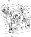
- Fig. 1
- is a perspective view of a rotary cutting deck with a height of cut adjustment mechanism according to a first embodiment of the invention.
- Fig. 2
- is an exploded perspective view of a rotary cutting deck with a height of cut adjustment mechanism according to a first embodiment of the invention.
- Fig. 3
- is a perspective view of a height of cut adjustment mechanism according to a first embodiment of the invention.
- Fig. 4
- is a cross section view of a height of cut adjustment mechanism in the locked position according to one embodiment of the present invention.
- Fig. 5
- is a cross section view of a height of cut adjustment mechanism in the unlocked position according to one embodiment of the present invention.
- Fig. 6
- is a perspective view of a rough mower having several rotary cutting decks mounted on lift arms extending from a traction vehicle, with height of cut adjustment mechanisms, in a preferred embodiment of the invention.
- As shown in
Figs. 1 and2 , in a first embodiment,rotary cutting deck 100 may be carried by a traction vehicle for a rough mower. Each rotary cutting deck includes a circular inverted dish-shaped cutting chamber 102. A motor such ashydrostatic motor 104 may be mounted to the upper top surface of the rotary cutting deck. The motor turns a cutting blade attached to a generally vertically aligned spindle under the deck. The rotary cutting deck is supported over the ground surface by a front pair ofrollers 106, casters or wheels, and arear roller 108. - In one embodiment, as shown in
Fig. 6 , three or more rotary cutting decks may be mounted to thetraction vehicle 101. Each rotary cutting deck may be pivotably supported at the end of alift arm 103 which the operator may actuate with one or more hydraulic cylinders or electric lift mechanisms to raise or lower the rotary cutting decks between mowing positions and transport positions. - In one embodiment, one or more rollers, casters or
wheels 106 are rotatably mounted to and supported byaxle 110 at or near the front of the rotary cutting deck. One or morerear rollers 108 are rotatably mounted to and supported by internal shaft oraxle 112 at or adjacent the rear of the rotary cutting deck. Alternatively, the rear of the rotary cutting deck may be supported by an axle with one or more casters or wheels. - In one embodiment, the height of cut adjustment mechanism of the present invention may be connected to the front and rear axles of the rotary cutting deck so that the mower deck can be raised or lowered to various different height of cut positions. The height of cut may be set by pivoting a front pair and a rear pair of height of cut
arms 114 to specified positions and then locking the height of cut arms in place. - In one embodiment, each height of cut arm has a first or
lower end 116 where the end of an axle is mounted. The front axle extends between the front pair of height of cut arms, and the rear axle extends between the rear pair of height of cut arms. Each of the pair of front arms should be pivoted to the same height of cut position, and each of the pair of rear arms also should be pivoted to a corresponding height of cut position so that the deck may have a slight forward rake during mowing, preferably with the front of the deck about 0,3175 cm (1/8 inch) lower than the back. - In one embodiment, a second or
upper end 118 of each height of cut arm is pivotably mounted to the rotary cutting deck. For example, a rod or threadedmember 120 may be inserted through an opening in the second or upper end of the height of cut arm and then through a corresponding opening in height ofcut support 122 mounted on the top surface of the deck. The rod provides a pivot axis for the height of cut arm. Height ofcut support 122 may be mounted onto the top surface of the deck using threaded fasteners through a flange portion of the height of cut support and throughcross members 124 that are secured to the top surface of the deck. - In one embodiment, each height of
cut arm 114 may be a steel casting.Notch lock 128 may be positioned on or adjacent each height of cut arm. For example,notch lock 128 may be inserted intoslot 126 or opening between the first and second ends of each height of cut arm. The notch lock, whether inserted into the slot or otherwise positioned on or adjacent the height of cut arm, is movable between a locked position to hold the height of cut arm at each desired cutting height, and an unlocked position allowing the height of cut arm to pivot with respect to the rotary cutting deck. - In one embodiment,
lever 130 may engage the notch lock and move, shift or slide the notch lock between locked and unlocked positions. In the locked position,notch lock 128 may engagenotch plate 132 at a desired height of cut, while in the unlocked position,notch lock 128 may disengagenotch plate 132. Alternatively, instead of engaging a notch plate, each notch lock may engage a surface portion of the deck or height of cut support at each specified cutting height in the locked position. - In one embodiment,
notch plate 132 may be secured to height ofcut support 122 with rivets or other attachment means. The notch plate may have a series of regularly spaced grooves orteeth 134 which demarcate the various height of cut positions available. The notch lock may have corresponding grooves orteeth 136 that engage or grip the notch plate at each specified height of cut position. - In one embodiment, the grooves or teeth on the notch plate are aligned in rows perpendicular to an
arcuate slot 138 through the notch plate. The arcuate slot in the notch plate may be aligned with a correspondingarcuate slot 140 in the height of cut support as the notch plate is secured to the height of cut support. The height of cut support may be an investment casting. - In one embodiment, rod or threaded
member 142 is pivotably attached tolever 130.Rod 142 may be inserted through the notch lock and through the arcuate slots in the notch plate and height of cut support. Height ofcut indicator 144 may be held on the end ofrod 142 using aspring washer 146 andnut 148, urging the rod and notch lock toward the locked position. The height of cut indicator may point to visible markings adjacent the slot of the height of cut support to show the actual height of cut position where the notch lock engages the notch plate. - In one embodiment, an operator may pivot lever 130 between a locked and an unlocked position. In the locked position, the lever cams to push the rod to compress the spring washer and maintain the notch lock in engagement with the notch lock plate at a specified height of cut position. In the unlocked position, the lever cams to pull the rod to decompress the spring washer so that the notch lock can disengage the notch lock plate. The notch lock may have a pair of
ears 150 that a shoulder on the lever pulls outwardly when the lever is pivoted to the unlocked position. By pulling the notch lock outwardly by its ears, the lever urges the notch lock away from engagement with the notch plate. - In one embodiment, the height of cut arms may be identical for all of the front and rear positions of the rotary cutting deck. Each height of cut arm may be reversible so that the arm may turned around and used in either front position or rear position, and still provide the rotary cutting deck with a forward rake. The reversible height of cut arm feature may be accomplished by locating the
notch lock slot 140 in each height of cut arm slightly off center from the midpoint of the arm. The off center location allows the height of cut arms to be reversible, while the front of the rotary cutting deck may be positioned slightly lower than the rear of the deck, sometimes referred to as a forward rake. - In
Figs. 1-5 , only one rotary cutting deck is shown.Fig. 6 showstraction vehicle 101 that carries multiple rotary cutting decks, each rotary cutting deck supported on alift arm 103 extending from the vehicle. Each cutting deck may be raised and lowered by use of hydraulic controls that may be operated from the vehicle. - The invention provides a relatively simple and inexpensive mechanism for adjusting the height of cut of a rotary cutting deck mounted to a lift arm of a traction vehicle. The height of cut adjustment mechanism is rugged and provides for stabilization of the rotary cutting units at each specified cutting height.
- Having described the preferred embodiment, it will become apparent that various modifications can be made without departing from the scope of the invention as defined in the accompanying claims.
Claims (6)
- A height of cut adjustment mechanism with a rotary cutting deck (100) mounted on a lift arm (103) extending from a traction vehicle (101),
comprising a pair of height of cut arms (114), each height of cut arm (114) having a first lower end (116) where an end of an axle is mounted,
characterized by a second upper end (118) pivotably mounted to a height of cut support (122) extending over the rotary cutting deck (100), and
a slot (126) through the height of cut arm (114) between the first and second ends (116, 118); and
a notch lock (128) inserted into the slot (126) and movable between a locked position extending through the slot (126) to engage with a plate (132) behind the slot (126) and attached to the height of cut support (122) for holding the height of cut arm (114) at a desired cutting height, and
an unlocked position disengaging the plate (132) and allowing the height of cut arm (114) to pivot with respect to the rotary cutting deck (100). - The height of cut adjustment mechanism according to claim 1, characterized by a lever (130) attached to each notch lock (128) to move the notch lock (128) between the locked position and the unlocked position.
- The height of cut adjustment mechanism according to claim 2, characterized by a rod (142) extending from the lever (130) through the notch lock (128), and a spring washer (146) urging the rod (142) into the locked position.
- The height of cut adjustment mechanism according to claims 2 or 3, characterized by a pair of ears (150) on the notch lock (128) that the lever (130) pulls to move the notch lock (128) from the locked position to the unlocked position.
- The height of cut adjustment mechanism according to one or several of the previous claims, characterized in that each of the notch lock (128) and the notch plate (132) having a plurality interengaging teeth (134).
- The height of cut adjustment mechanism according to one or several of the previous claims, characterized by a front pair and a rear pair of height of cut arms (114); at least one roller (108) mounted to the front axle extending between the first lower ends of the front pair of height of cut arms (114); and at least one roller (108) mounted to the rear axle extending between the first lower ends of the rear pair of height of cut arms (114).
Applications Claiming Priority (1)
| Application Number | Priority Date | Filing Date | Title |
|---|---|---|---|
| US12/192,435 US7716907B2 (en) | 2008-08-15 | 2008-08-15 | Height of cut adjustment mechanism for rotary cutting deck |
Publications (2)
| Publication Number | Publication Date |
|---|---|
| EP2153711A1 EP2153711A1 (en) | 2010-02-17 |
| EP2153711B1 true EP2153711B1 (en) | 2017-08-23 |
Family
ID=41323923
Family Applications (1)
| Application Number | Title | Priority Date | Filing Date |
|---|---|---|---|
| EP09167073.7A Active EP2153711B1 (en) | 2008-08-15 | 2009-08-03 | Height of cut adjustment mechanism |
Country Status (2)
| Country | Link |
|---|---|
| US (1) | US7716907B2 (en) |
| EP (1) | EP2153711B1 (en) |
Families Citing this family (14)
| Publication number | Priority date | Publication date | Assignee | Title |
|---|---|---|---|---|
| US8069639B2 (en) * | 2008-10-29 | 2011-12-06 | Husqvarna Outdoor Products Inc. | Wheel height adjuster for walk-behind mower |
| GB2494244B (en) * | 2011-09-01 | 2016-06-22 | Skybest Electric Appliance Suzhou Co Ltd | Lawnmower |
| US20130118139A1 (en) * | 2011-11-15 | 2013-05-16 | Agri-Fab, Inc. | Sweeper height adjustment assembly |
| US9301444B2 (en) | 2014-05-02 | 2016-04-05 | Deere & Company | Rotary cutting deck height of cut adjustment mechanism |
| US9775288B2 (en) * | 2015-02-27 | 2017-10-03 | Deere & Company | Rotary cutting deck with asymmetric rear discharge opening |
| US10609863B2 (en) | 2017-08-01 | 2020-04-07 | Deere & Company | Mower deck gauge wheel adjustment mechanism |
| US11160207B2 (en) * | 2017-10-26 | 2021-11-02 | Firefly Automatix, Inc. | Height adjustable mower deck |
| US10939615B2 (en) * | 2017-10-26 | 2021-03-09 | Firefly Automatix, Inc. | Adjustable mower deck |
| US11206759B2 (en) * | 2017-11-21 | 2021-12-28 | The Toro Company | Mower quick height of cut adjustment |
| US10694665B2 (en) * | 2017-12-14 | 2020-06-30 | Clark Equipment Company | Cutter-deck leveling fine adjustment |
| KR102821566B1 (en) * | 2019-01-03 | 2025-06-17 | 엘에스엠트론 주식회사 | Auxiliary wheels for lawn mower |
| US11606899B2 (en) | 2020-03-04 | 2023-03-21 | Deere & Company | Height of cut and rake adjustment system |
| US11871695B2 (en) * | 2021-03-25 | 2024-01-16 | Deere & Company | Height of cut adjustment system |
| CN216567136U (en) | 2021-10-15 | 2022-05-24 | 创科无线普通合伙 | Grass cutter |
Family Cites Families (23)
| Publication number | Priority date | Publication date | Assignee | Title |
|---|---|---|---|---|
| US1466372A (en) * | 1920-04-09 | 1923-08-28 | Artemas Ward | Coin-controlled vending machine |
| US1697510A (en) * | 1927-05-14 | 1929-01-01 | Doehler Die Casting Co | Vending machine |
| US2990084A (en) * | 1956-05-14 | 1961-06-27 | Oak Mfg Co Inc | Vending machine |
| US3421776A (en) * | 1966-10-05 | 1969-01-14 | Singer Co | Lawnmower height adjustment apparatus |
| US3649828A (en) * | 1970-06-24 | 1972-03-14 | Gilson Brothers Co | Adjustable wheel bracket assembly |
| US3872654A (en) * | 1973-10-09 | 1975-03-25 | Emerson Electric Co | Mobile leaf shredding and bagging machine |
| US4109825A (en) * | 1976-12-08 | 1978-08-29 | Weitzman Barry Sheldon | Rotatable compartmentalized vending apparatus |
| US4321785A (en) * | 1980-12-08 | 1982-03-30 | Ataco Steel Products Co. | Wheel height adjuster |
| US5065568A (en) | 1990-07-26 | 1991-11-19 | Deere & Company | Mower deck height adjustment mechanism |
| US5085044A (en) | 1990-09-24 | 1992-02-04 | Simplicity Manufacturing, Inc. | Two-blade mower deck with infinite height adjustment |
| US5142850A (en) | 1991-06-14 | 1992-09-01 | Deere & Company | Mower deck height adjustment mechanism |
| US5261564A (en) * | 1991-11-22 | 1993-11-16 | Jax Vending, Inc. | Drum-type vending machine |
| US5381648A (en) | 1993-05-28 | 1995-01-17 | Deere & Company | Mower deck height adjustment mechanism |
| US5472074A (en) * | 1994-03-09 | 1995-12-05 | Milcetic; Duncan J. | Coin operated dispensing machine |
| US5797252A (en) | 1996-05-13 | 1998-08-25 | Deere & Company | Height of cut adjustment mechanism |
| US5749209A (en) * | 1996-09-05 | 1998-05-12 | Mtd Products Inc | Single lever height adjustment mechanism and method for a lawn mower |
| US6336312B1 (en) | 1997-02-03 | 2002-01-08 | Textron Inc. | Gang-Type rotary lawn mower with multiple rear rollers |
| US6047530A (en) | 1997-02-03 | 2000-04-11 | Textron, Inc. | Gang-type rotary lawn mower |
| US5845471A (en) * | 1997-06-20 | 1998-12-08 | Deere & Company | Adjustable gauge wheel for mower deck |
| US6041584A (en) * | 1998-04-29 | 2000-03-28 | Deere & Company | Adjustable gauge wheel support structure |
| GB2352956B (en) | 1999-08-10 | 2003-05-07 | Bosch Gmbh Robert | Rotary lawnmowers |
| DE202004015965U1 (en) | 2004-10-15 | 2004-12-16 | Wolf-Geräte AG | joint arrangement |
| US7478519B2 (en) * | 2005-10-13 | 2009-01-20 | Deere & Company | Mounting rotary cutting deck to lift arm |
-
2008
- 2008-08-15 US US12/192,435 patent/US7716907B2/en active Active
-
2009
- 2009-08-03 EP EP09167073.7A patent/EP2153711B1/en active Active
Non-Patent Citations (1)
| Title |
|---|
| None * |
Also Published As
| Publication number | Publication date |
|---|---|
| US20100037578A1 (en) | 2010-02-18 |
| US7716907B2 (en) | 2010-05-18 |
| EP2153711A1 (en) | 2010-02-17 |
Similar Documents
| Publication | Publication Date | Title |
|---|---|---|
| EP2153711A1 (en) | Height of cut adjustment mechanism | |
| US9301444B2 (en) | Rotary cutting deck height of cut adjustment mechanism | |
| US9370139B2 (en) | Reel mower with pivotal footrest providing access to center rear cutting unit | |
| US7540134B1 (en) | Riding mower with deck height adjustment | |
| US8438822B2 (en) | Height of cut adjustment system for mower cutting deck | |
| EP3874933B1 (en) | Height of cut and rake adjustment system | |
| US6644416B2 (en) | Tiller | |
| US7877973B2 (en) | Riding mower | |
| CA2234406A1 (en) | Adjustable gauge wheel for mower deck | |
| US9750172B2 (en) | Turf implement having turf slicing reel with easily adjustable height control | |
| US20090101234A1 (en) | Stump cutter with a weight centered power train | |
| US20240172586A1 (en) | Walk-Behind Lawnmower with Cutting Height Adjuster | |
| NZ217699A (en) | Wheel and skid supported rotary mower: pitching drawbar adjustable to set cutting height | |
| US5960615A (en) | Swiveling wheel attachment for a lawnmower | |
| CA1253007A (en) | Lawn and garden maintenance apparatus | |
| US9642304B1 (en) | Floating deck system for riding lawn mowers | |
| US11871695B2 (en) | Height of cut adjustment system | |
| US9775288B2 (en) | Rotary cutting deck with asymmetric rear discharge opening | |
| JPS594855Y2 (en) | Walking type reaping harvester | |
| US7654065B2 (en) | Offsetting cutting units for a grass mowing machine | |
| US20260101840A1 (en) | Height adjustment systems for mowers | |
| US4532998A (en) | Lawn edger device | |
| BR202017026599U2 (en) | CONSTRUCTIVE ARRANGEMENT APPLIED TO VEGETATION CUTTER, SHRUBS, MATO AND GRASS IN THE FORM OF TRAILER | |
| US20090084079A1 (en) | Device for preparing grass for mowing |
Legal Events
| Date | Code | Title | Description |
|---|---|---|---|
| PUAI | Public reference made under article 153(3) epc to a published international application that has entered the european phase |
Free format text: ORIGINAL CODE: 0009012 |
|
| AK | Designated contracting states |
Kind code of ref document: A1 Designated state(s): AT BE BG CH CY CZ DE DK EE ES FI FR GB GR HR HU IE IS IT LI LT LU LV MC MK MT NL NO PL PT RO SE SI SK SM TR |
|
| AX | Request for extension of the european patent |
Extension state: AL BA RS |
|
| 17P | Request for examination filed |
Effective date: 20100817 |
|
| 17Q | First examination report despatched |
Effective date: 20100910 |
|
| GRAP | Despatch of communication of intention to grant a patent |
Free format text: ORIGINAL CODE: EPIDOSNIGR1 |
|
| INTG | Intention to grant announced |
Effective date: 20170308 |
|
| GRAS | Grant fee paid |
Free format text: ORIGINAL CODE: EPIDOSNIGR3 |
|
| GRAA | (expected) grant |
Free format text: ORIGINAL CODE: 0009210 |
|
| AK | Designated contracting states |
Kind code of ref document: B1 Designated state(s): AT BE BG CH CY CZ DE DK EE ES FI FR GB GR HR HU IE IS IT LI LT LU LV MC MK MT NL NO PL PT RO SE SI SK SM TR |
|
| REG | Reference to a national code |
Ref country code: GB Ref legal event code: FG4D |
|
| REG | Reference to a national code |
Ref country code: CH Ref legal event code: EP |
|
| REG | Reference to a national code |
Ref country code: AT Ref legal event code: REF Ref document number: 920276 Country of ref document: AT Kind code of ref document: T Effective date: 20170915 |
|
| REG | Reference to a national code |
Ref country code: IE Ref legal event code: FG4D |
|
| REG | Reference to a national code |
Ref country code: DE Ref legal event code: R096 Ref document number: 602009047862 Country of ref document: DE |
|
| REG | Reference to a national code |
Ref country code: NL Ref legal event code: MP Effective date: 20170823 |
|
| REG | Reference to a national code |
Ref country code: LT Ref legal event code: MG4D |
|
| REG | Reference to a national code |
Ref country code: AT Ref legal event code: MK05 Ref document number: 920276 Country of ref document: AT Kind code of ref document: T Effective date: 20170823 |
|
| PG25 | Lapsed in a contracting state [announced via postgrant information from national office to epo] |
Ref country code: AT Free format text: LAPSE BECAUSE OF FAILURE TO SUBMIT A TRANSLATION OF THE DESCRIPTION OR TO PAY THE FEE WITHIN THE PRESCRIBED TIME-LIMIT Effective date: 20170823 Ref country code: FI Free format text: LAPSE BECAUSE OF FAILURE TO SUBMIT A TRANSLATION OF THE DESCRIPTION OR TO PAY THE FEE WITHIN THE PRESCRIBED TIME-LIMIT Effective date: 20170823 Ref country code: SE Free format text: LAPSE BECAUSE OF FAILURE TO SUBMIT A TRANSLATION OF THE DESCRIPTION OR TO PAY THE FEE WITHIN THE PRESCRIBED TIME-LIMIT Effective date: 20170823 Ref country code: LT Free format text: LAPSE BECAUSE OF FAILURE TO SUBMIT A TRANSLATION OF THE DESCRIPTION OR TO PAY THE FEE WITHIN THE PRESCRIBED TIME-LIMIT Effective date: 20170823 Ref country code: HR Free format text: LAPSE BECAUSE OF FAILURE TO SUBMIT A TRANSLATION OF THE DESCRIPTION OR TO PAY THE FEE WITHIN THE PRESCRIBED TIME-LIMIT Effective date: 20170823 Ref country code: NL Free format text: LAPSE BECAUSE OF FAILURE TO SUBMIT A TRANSLATION OF THE DESCRIPTION OR TO PAY THE FEE WITHIN THE PRESCRIBED TIME-LIMIT Effective date: 20170823 Ref country code: NO Free format text: LAPSE BECAUSE OF FAILURE TO SUBMIT A TRANSLATION OF THE DESCRIPTION OR TO PAY THE FEE WITHIN THE PRESCRIBED TIME-LIMIT Effective date: 20171123 |
|
| PG25 | Lapsed in a contracting state [announced via postgrant information from national office to epo] |
Ref country code: GR Free format text: LAPSE BECAUSE OF FAILURE TO SUBMIT A TRANSLATION OF THE DESCRIPTION OR TO PAY THE FEE WITHIN THE PRESCRIBED TIME-LIMIT Effective date: 20171124 Ref country code: ES Free format text: LAPSE BECAUSE OF FAILURE TO SUBMIT A TRANSLATION OF THE DESCRIPTION OR TO PAY THE FEE WITHIN THE PRESCRIBED TIME-LIMIT Effective date: 20170823 Ref country code: PL Free format text: LAPSE BECAUSE OF FAILURE TO SUBMIT A TRANSLATION OF THE DESCRIPTION OR TO PAY THE FEE WITHIN THE PRESCRIBED TIME-LIMIT Effective date: 20170823 Ref country code: LV Free format text: LAPSE BECAUSE OF FAILURE TO SUBMIT A TRANSLATION OF THE DESCRIPTION OR TO PAY THE FEE WITHIN THE PRESCRIBED TIME-LIMIT Effective date: 20170823 Ref country code: IS Free format text: LAPSE BECAUSE OF FAILURE TO SUBMIT A TRANSLATION OF THE DESCRIPTION OR TO PAY THE FEE WITHIN THE PRESCRIBED TIME-LIMIT Effective date: 20171223 Ref country code: BG Free format text: LAPSE BECAUSE OF FAILURE TO SUBMIT A TRANSLATION OF THE DESCRIPTION OR TO PAY THE FEE WITHIN THE PRESCRIBED TIME-LIMIT Effective date: 20171123 |
|
| PG25 | Lapsed in a contracting state [announced via postgrant information from national office to epo] |
Ref country code: DK Free format text: LAPSE BECAUSE OF FAILURE TO SUBMIT A TRANSLATION OF THE DESCRIPTION OR TO PAY THE FEE WITHIN THE PRESCRIBED TIME-LIMIT Effective date: 20170823 Ref country code: CZ Free format text: LAPSE BECAUSE OF FAILURE TO SUBMIT A TRANSLATION OF THE DESCRIPTION OR TO PAY THE FEE WITHIN THE PRESCRIBED TIME-LIMIT Effective date: 20170823 Ref country code: RO Free format text: LAPSE BECAUSE OF FAILURE TO SUBMIT A TRANSLATION OF THE DESCRIPTION OR TO PAY THE FEE WITHIN THE PRESCRIBED TIME-LIMIT Effective date: 20170823 |
|
| REG | Reference to a national code |
Ref country code: DE Ref legal event code: R097 Ref document number: 602009047862 Country of ref document: DE |
|
| PG25 | Lapsed in a contracting state [announced via postgrant information from national office to epo] |
Ref country code: IT Free format text: LAPSE BECAUSE OF FAILURE TO SUBMIT A TRANSLATION OF THE DESCRIPTION OR TO PAY THE FEE WITHIN THE PRESCRIBED TIME-LIMIT Effective date: 20170823 Ref country code: SM Free format text: LAPSE BECAUSE OF FAILURE TO SUBMIT A TRANSLATION OF THE DESCRIPTION OR TO PAY THE FEE WITHIN THE PRESCRIBED TIME-LIMIT Effective date: 20170823 Ref country code: SK Free format text: LAPSE BECAUSE OF FAILURE TO SUBMIT A TRANSLATION OF THE DESCRIPTION OR TO PAY THE FEE WITHIN THE PRESCRIBED TIME-LIMIT Effective date: 20170823 Ref country code: EE Free format text: LAPSE BECAUSE OF FAILURE TO SUBMIT A TRANSLATION OF THE DESCRIPTION OR TO PAY THE FEE WITHIN THE PRESCRIBED TIME-LIMIT Effective date: 20170823 |
|
| PLBE | No opposition filed within time limit |
Free format text: ORIGINAL CODE: 0009261 |
|
| STAA | Information on the status of an ep patent application or granted ep patent |
Free format text: STATUS: NO OPPOSITION FILED WITHIN TIME LIMIT |
|
| 26N | No opposition filed |
Effective date: 20180524 |
|
| PG25 | Lapsed in a contracting state [announced via postgrant information from national office to epo] |
Ref country code: SI Free format text: LAPSE BECAUSE OF FAILURE TO SUBMIT A TRANSLATION OF THE DESCRIPTION OR TO PAY THE FEE WITHIN THE PRESCRIBED TIME-LIMIT Effective date: 20170823 |
|
| PG25 | Lapsed in a contracting state [announced via postgrant information from national office to epo] |
Ref country code: MC Free format text: LAPSE BECAUSE OF FAILURE TO SUBMIT A TRANSLATION OF THE DESCRIPTION OR TO PAY THE FEE WITHIN THE PRESCRIBED TIME-LIMIT Effective date: 20170823 |
|
| REG | Reference to a national code |
Ref country code: CH Ref legal event code: PL |
|
| PG25 | Lapsed in a contracting state [announced via postgrant information from national office to epo] |
Ref country code: CH Free format text: LAPSE BECAUSE OF NON-PAYMENT OF DUE FEES Effective date: 20180831 Ref country code: LI Free format text: LAPSE BECAUSE OF NON-PAYMENT OF DUE FEES Effective date: 20180831 Ref country code: LU Free format text: LAPSE BECAUSE OF NON-PAYMENT OF DUE FEES Effective date: 20180803 |
|
| REG | Reference to a national code |
Ref country code: BE Ref legal event code: MM Effective date: 20180831 |
|
| REG | Reference to a national code |
Ref country code: IE Ref legal event code: MM4A |
|
| PG25 | Lapsed in a contracting state [announced via postgrant information from national office to epo] |
Ref country code: IE Free format text: LAPSE BECAUSE OF NON-PAYMENT OF DUE FEES Effective date: 20180803 |
|
| PG25 | Lapsed in a contracting state [announced via postgrant information from national office to epo] |
Ref country code: FR Free format text: LAPSE BECAUSE OF NON-PAYMENT OF DUE FEES Effective date: 20180831 Ref country code: BE Free format text: LAPSE BECAUSE OF NON-PAYMENT OF DUE FEES Effective date: 20180831 |
|
| PG25 | Lapsed in a contracting state [announced via postgrant information from national office to epo] |
Ref country code: MT Free format text: LAPSE BECAUSE OF NON-PAYMENT OF DUE FEES Effective date: 20180803 |
|
| PG25 | Lapsed in a contracting state [announced via postgrant information from national office to epo] |
Ref country code: TR Free format text: LAPSE BECAUSE OF FAILURE TO SUBMIT A TRANSLATION OF THE DESCRIPTION OR TO PAY THE FEE WITHIN THE PRESCRIBED TIME-LIMIT Effective date: 20170823 |
|
| PG25 | Lapsed in a contracting state [announced via postgrant information from national office to epo] |
Ref country code: PT Free format text: LAPSE BECAUSE OF FAILURE TO SUBMIT A TRANSLATION OF THE DESCRIPTION OR TO PAY THE FEE WITHIN THE PRESCRIBED TIME-LIMIT Effective date: 20170823 Ref country code: HU Free format text: LAPSE BECAUSE OF FAILURE TO SUBMIT A TRANSLATION OF THE DESCRIPTION OR TO PAY THE FEE WITHIN THE PRESCRIBED TIME-LIMIT; INVALID AB INITIO Effective date: 20090803 |
|
| PG25 | Lapsed in a contracting state [announced via postgrant information from national office to epo] |
Ref country code: MK Free format text: LAPSE BECAUSE OF NON-PAYMENT OF DUE FEES Effective date: 20170823 Ref country code: CY Free format text: LAPSE BECAUSE OF FAILURE TO SUBMIT A TRANSLATION OF THE DESCRIPTION OR TO PAY THE FEE WITHIN THE PRESCRIBED TIME-LIMIT Effective date: 20170823 |
|
| PGFP | Annual fee paid to national office [announced via postgrant information from national office to epo] |
Ref country code: DE Payment date: 20210721 Year of fee payment: 13 |
|
| REG | Reference to a national code |
Ref country code: DE Ref legal event code: R119 Ref document number: 602009047862 Country of ref document: DE |
|
| PG25 | Lapsed in a contracting state [announced via postgrant information from national office to epo] |
Ref country code: DE Free format text: LAPSE BECAUSE OF NON-PAYMENT OF DUE FEES Effective date: 20230301 |
|
| PGFP | Annual fee paid to national office [announced via postgrant information from national office to epo] |
Ref country code: GB Payment date: 20250827 Year of fee payment: 17 |