EP2152427B1 - Crushing machines - Google Patents
Crushing machines Download PDFInfo
- Publication number
- EP2152427B1 EP2152427B1 EP08750474.2A EP08750474A EP2152427B1 EP 2152427 B1 EP2152427 B1 EP 2152427B1 EP 08750474 A EP08750474 A EP 08750474A EP 2152427 B1 EP2152427 B1 EP 2152427B1
- Authority
- EP
- European Patent Office
- Prior art keywords
- screen
- conveyor
- crushing
- screening unit
- machine
- Prior art date
- Legal status (The legal status is an assumption and is not a legal conclusion. Google has not performed a legal analysis and makes no representation as to the accuracy of the status listed.)
- Active
Links
Images

Classifications
-
- B—PERFORMING OPERATIONS; TRANSPORTING
- B02—CRUSHING, PULVERISING, OR DISINTEGRATING; PREPARATORY TREATMENT OF GRAIN FOR MILLING
- B02C—CRUSHING, PULVERISING, OR DISINTEGRATING IN GENERAL; MILLING GRAIN
- B02C23/00—Auxiliary methods or auxiliary devices or accessories specially adapted for crushing or disintegrating not provided for in preceding groups or not specially adapted to apparatus covered by a single preceding group
- B02C23/04—Safety devices
-
- B—PERFORMING OPERATIONS; TRANSPORTING
- B02—CRUSHING, PULVERISING, OR DISINTEGRATING; PREPARATORY TREATMENT OF GRAIN FOR MILLING
- B02C—CRUSHING, PULVERISING, OR DISINTEGRATING IN GENERAL; MILLING GRAIN
- B02C2/00—Crushing or disintegrating by gyratory or cone crushers
- B02C2/007—Feeding devices
-
- B—PERFORMING OPERATIONS; TRANSPORTING
- B02—CRUSHING, PULVERISING, OR DISINTEGRATING; PREPARATORY TREATMENT OF GRAIN FOR MILLING
- B02C—CRUSHING, PULVERISING, OR DISINTEGRATING IN GENERAL; MILLING GRAIN
- B02C21/00—Disintegrating plant with or without drying of the material
- B02C21/02—Transportable disintegrating plant
- B02C21/026—Transportable disintegrating plant self-propelled
-
- B—PERFORMING OPERATIONS; TRANSPORTING
- B02—CRUSHING, PULVERISING, OR DISINTEGRATING; PREPARATORY TREATMENT OF GRAIN FOR MILLING
- B02C—CRUSHING, PULVERISING, OR DISINTEGRATING IN GENERAL; MILLING GRAIN
- B02C23/00—Auxiliary methods or auxiliary devices or accessories specially adapted for crushing or disintegrating not provided for in preceding groups or not specially adapted to apparatus covered by a single preceding group
- B02C23/02—Feeding devices
-
- B—PERFORMING OPERATIONS; TRANSPORTING
- B02—CRUSHING, PULVERISING, OR DISINTEGRATING; PREPARATORY TREATMENT OF GRAIN FOR MILLING
- B02C—CRUSHING, PULVERISING, OR DISINTEGRATING IN GENERAL; MILLING GRAIN
- B02C23/00—Auxiliary methods or auxiliary devices or accessories specially adapted for crushing or disintegrating not provided for in preceding groups or not specially adapted to apparatus covered by a single preceding group
- B02C23/08—Separating or sorting of material, associated with crushing or disintegrating
-
- Y—GENERAL TAGGING OF NEW TECHNOLOGICAL DEVELOPMENTS; GENERAL TAGGING OF CROSS-SECTIONAL TECHNOLOGIES SPANNING OVER SEVERAL SECTIONS OF THE IPC; TECHNICAL SUBJECTS COVERED BY FORMER USPC CROSS-REFERENCE ART COLLECTIONS [XRACs] AND DIGESTS
- Y10—TECHNICAL SUBJECTS COVERED BY FORMER USPC
- Y10T—TECHNICAL SUBJECTS COVERED BY FORMER US CLASSIFICATION
- Y10T29/00—Metal working
- Y10T29/49—Method of mechanical manufacture
- Y10T29/49826—Assembling or joining
Definitions
- This invention relates to crushing machines for crushing aggregate and the like, and in particular to mobile crushing machines such as are used in quarries, or for recycling demolition waste.
- a cone crusher has a pair of frusto-conical members arranged with their apexes upwards, and with an annular gap between them that decreases in width from top to bottom.
- the inner cone is rotatable relative to the outer cone on an eccentric, so that material fed in at the top is crushed between the cones as the gap varies, and then falls out at the bottom.
- Cone crushers are efficient at crushing various types of material, such as rock or stone, to a given size. However, it is important to ensure that no metal is fed into the crusher, since this can cause extensive damage to the cones.
- WO 2005/099903 discloses a crusher apparatus in which a feeder device is adjustable between an operative feeding position in which the material to be crushed is supplied to the inlet of a crusher device and an inoperative position in which material can be discharged from the feeder device without being fed to the crusher device.
- US 3 963 181 discloses a system for producing cracker meal by reclaiming baked goods from wrappers and separating the cracker material from the wrappers using a shaker screen.
- US 2004/0035963 discloses a mobile crushing unit having a vibrating feeder and in which a transport locking arrangement utilises downwardly rotatable side walls of the feeder hopper of the vibrating feeder to lock the vibrating feeder substantially rigidly to the framework of the crushing units at a transparent position.
- US 5 074 435 discloses a system for controlling the feed rate from a vibrating feeder including a sensing device for sensing the amount of material being discharged from the feeder.
- the sensing device can be connected to a controller that can change a slope of the feeder to control the amount of material to be discharged from the feeder.
- US 3 647 150 discloses a screening unit for a portable crusher system in which a series of vibrating screens are provided to screen and separate into different sizes material that has been through the crusher. Oversized material can be fed back to a jaw crusher.
- US 2002/0044828 discloses a mobile rock crusher which has a feeder device and a screen which separates larger diameter material from smaller diameter material.
- the larger diameter material is translated over a first screen and falls into a first crusher mounted to a frame below the first screen.
- the smaller diameter material falls through the first screen.
- a second crusher may be provided.
- US 4 383 651 discloses a mobile screening and crushing plant which comprises a crusher, a screening device and a conveyor mounted on a trailer.
- a feed conveyor feeds material to the screening device which separates the material. Material which passes through the triple deck vibrating screen is conveyed to a discharge chute. Oversize material is passed to a crusher which discharges crushed material onto the feed conveyor to be returned to the screening device.
- US 2003/0146315 discloses a screen assembly including a conveyor pivotably mounted beneath a screen for segregation of fractions of material such as from a mobile crusher. Hydraulic telescopic arms are provided which can raise or lower the conveyor between an operative position and an inoperative position. In the inoperative position the conveyor is angularly displaced to provide access to the underside of the screen.
- EP 0 382 922 describes a mobile crusher having a jaw crusher and a crushing material charging device arranged to deliver material to be crushed to the crusher and from the crusher to a main conveyor.
- the charging device is provided with a screen.
- EP 0 301 798 discloses a screening apparatus for screening particulate material and the screening apparatus comprises a base frame, an elevating conveyor mounted on a base frame and a screen mounted on a sub frame of the base frame. An angle of operation of the screening unit can be adjusted depending on the size and rate of feed of the material.
- a crushing machine including a crushing means, a feed conveyor for feeding material to the crushing means, a detector for detecting metal in the material on the feed conveyor, and a bypass chute for the crushing means, the feed conveyor being movable between a normal operating position in which the material is fed to the crushing means and a bypass position in which the material is fed to the bypass chute, the arrangement being such that on detection of metal in the material the feed conveyor is stopped and moved from the normal operating position to the bypass position so that the material with the metal is discharged into the bypass chute.
- This crushing machine therefore provides a much easier and quicker way of removing metal from the material before it reaches the crushing means, since on detection of metal the conveyor can simply be stopped, and moved into the bypass position to discharge the metal into the bypass chute without the operator needing to look for the metal and remove it manually. It is particularly advantageous where the crushing means is a cone crusher, but may also be useful for other types of crusher.
- the feed conveyor is stopped again, moved back into the normal operating position and started, to resume discharge into the crushing means.
- the metal detector is preferably mounted on the feed conveyor, and sends a signal to the operator when metal is detected.
- the feed conveyor may be movable between the two positions by means of at least one hydraulic piston and cylinder assembly.
- the or each piston and cylinder assembly is conveniently double-acting.
- the piston may be connected to the feed conveyor, and the cylinder to a stationary part of the machine, although the opposite way round would also be possible.
- the piston and cylinder assembly or assemblies moves the feed conveyor longitudinally.
- the bypass chute is preferably arranged between the feed conveyor and the crushing means, so that the feed conveyor moves rearwardly (opposite to the direction of travel of the material) from its normal operating position into its bypass position.
- the piston of the piston and cylinder assembly will be extended when the conveyor is in its normal operating position, and retracted when it is in its bypass position.
- the piston and cylinder assembly may have load-holding valves to lock the piston in position.
- the crushed material which exits the crushing means may fall onto a main conveyor for transport elsewhere.
- the material discharged into the bypass chute will be diverted away from the crushed material. It may simply fall to the ground, or into a convenient container.
- the invention is particularly useful where the crushing machine is a mobile crusher, having a tracked or wheeled base on which are mounted the feed conveyor, the bypass chute, the crushing means, the main conveyor, a power unit (typically a diesel engine) and a control system (including both manual and electronic controls).
- a power unit typically a diesel engine
- a control system including both manual and electronic controls.
- the control system is used for operating the conveyors and the crushing means, and may be sophisticated.
- the control system may be adapted so that it automatically stops the feed conveyor when the signal is received from the metal detector. Further automation of the movement of the feed conveyor between the normal operating position and bypass position may be possible, but normally the operator will control these movements.
- cone crusher Another feature of a cone crusher is that it is more efficient and produces more evenly-sized crushed material, if the proportion of material that will pass through it without being crushed (commonly known as fines) is limited.
- One method of limiting the proportion of fines is to screen them out of the material before it is fed to the crusher. Currently, this requires a separate machine, which is expensive to buy (or hire) and to run. It also increases the time taken to process the material.
- the crushing machine may comprise a feed conveyor, a screening unit, a crushing means and a main conveyor, the arrangement being such that material to be crushed is fed from the feed conveyor to the screening unit, for separation into finer material which reaches the main conveyor without passing through the crushing means, and coarser material which is fed in the crushing means to the main conveyor.
- a single machine incorporates a screening function as well as a crushing function, enabling the finer material to be screened out and not to pass through the crushing means.
- This is particularly advantageous where the crushing means is a cone crusher. Providing both functions in one machine thus reduces costs, both capital costs and running costs, including transport costs.
- the screening unit preferably comprises a screen conveyor and a vibrating mesh screen. Material from the feed conveyor is passed to the screen conveyor, from where it exits onto the mesh screen. Finer material falls through the screen, and onto the main conveyor, while the coarser material slides off the screen and into the crushing means. It will be appreciated that the screen must be angled to the horizontal for the coarser material to slide off it.
- the screening unit is therefore conveniently arranged on the opposite side of the crushing means from the feed conveyor.
- the screening unit conveniently has a frame on which are mounted the screen and the screen conveyor.
- the frame is movable between an inoperative position, in which it is substantially horizontal, and an operative position, in which it is angled to the horizontal.
- the inoperative position is advantageous for transporting the machine.
- the screening unit may be moved between the two positions by at least one pair of hydraulic piston and cylinder assemblies, acting between a base of the machine and the screening unit.
- Preferably two pairs of assemblies are provided, one at each end of the screening unit. One pair acts vertically to lift the unit, while the other lifts and controls the angle of the unit.
- the screen conveyor is conveniently mounted on the frame by a further pair of piston and cylinder assemblies. These enable the angle of the screen conveyor to be adjusted relative to the screen, and also enable the screen conveyor to be lifted relative to the screen, to facilitate changing of the screen.
- the machine of Figure 1 is a mobile crushing machine for crushing stone, aggregate and the like.
- the machine comprises a base 1, on which are mounted a feed conveyor 2, crushing means 3, a power unit 4 including a control unit, and a main conveyor 5.
- the base 1 has tracks 6 and an elongate platform 7 on which the other parts are mounted, with the feed conveyor 2 at the rear end, and the main conveyor 5 at the front end.
- the feed conveyor 2 is of a known design, having a frame 8 for a powered belt 9 and a feed chute 10 at the rear end of the belt 9 to receive material to be crushed.
- the frame 8 is mounted on the platform 7 by two pairs of hydraulic piston and cylinder assemblies 11, 12.
- the assemblies 11 act vertically to raise and lower the forward end of the frame 8, with the cylinders 13 being attached to the platform 7, and the pistons 14 pivotally mounted to the frame 8.
- the assemblies 12 act to move the frame 8 in the longitudinal direction between the normal operating position of Figure 1 , and a bypass position of Figure 2 .
- the cylinders 15 are pivotally attached to an upstand 16 on the platform 7, while the pistons 17 are connected to an abutment 18 on the underside of the frame 8.
- the piston and cylinder assemblies 11, 12 are double-acting, and have load-holding valves (not shown) to lock the pistons in any desired position.
- the feed conveyor 2 also carries a metal detector 19, mounted near the forward end of the belt, and adapted to send a signal to the control unit when metal is detected in the material on the feed conveyor 2.
- the crushing means 3 comprises a cone crusher of known design, which need not be described further here. Material fed into the top of the crusher 3 from the forward end of the feed conveyor 2 is crushed, and falls out of the bottom of the crusher 3 onto the main conveyor 5.
- the main conveyor 5, mounted on the front end of the platform 7, is also of a known design, and will not be described further here.
- the power and control unit 4 is also mounted near the front end of the platform 7, and includes a diesel engine (not shown) as the power source for the machine, an hydraulic system (not shown) for operating the piston and cylinder assemblies 11, 12 and all other hydraulic components, and controls (not shown) for the machine. These are housed in a control area 20 for the machine operator.
- the controls include manual controls and electronic controls for automatically performing some operations.
- a bypass chute 21 is mounted on the platform 7 between the feed conveyor 2 and the crusher 3. Material fed into the top of the chute 21 will not fall onto the main conveyor 5, but instead will be discharged to the side of the machine, to fall onto the ground, or into a suitable container.
- Figure 1 shows the machine in its normal operating position.
- the feed conveyor 2 is raised by means of the assemblies 11, and the pistons 17 of the assemblies 12 are extended, so that the conveyor 2 is ready to discharge into the crusher 3. Then, in operation, material placed in the feed chute 10 is carried upwards by the feed conveyor 2, and discharged into the crusher 3. The crushed material falls out of the bottom of the crusher 3 onto the main conveyor 5, and is discharged at the forward end of that conveyor into a suitable container.
- the operator controls the conveyors 2, 5 and the crusher 3 from the control area 20.
- the metal detector detects the presence of metal in the material on the feed conveyor 2, it sends a signal to the electronic controls, which operate to stop the feed conveyor 2.
- the operator then actuates the assemblies 12, to retract the pistons 17, causing the feed conveyor 2 to move rearwardly into the bypass position shown in Figure 2 , where the material on the feed conveyor is discharged into the bypass chute 21, rather than the crusher 3.
- the operator then starts the feed conveyor 2 again, so that the material including the metal is discharged into the bypass chute to fall on the ground at the side of the machine.
- the conveyor 2 Once the operator is satisfied that the metal is no longer on the belt 9, he stops the conveyor 2 and actuates the assemblies 12 to extend the pistons 17 again, thus moving the feed conveyor 2 back into the normal operating position.
- the feed conveyor 2 can then be restarted, and normal operation resumed.
- Figure 3 shows the machine of Figure 1 in a position in which it can be transported on a low loader or the like, and also illustrates the second aspect of the invention. In relation to the first aspect of the invention, however, it will be noted that for transport, the feed conveyor 2 is in the bypass position.
- FIG. 3 The additional component of the machine shown in Figures 3 and 4 is a screening unit 30.
- the remainder of the machine is as shown in Figure 1 , and corresponding reference numerals have been applied to corresponding parts. Only the screening unit 30 will now be described.
- the screening unit 30 is mounted on the platform 7 between the crusher 3 and the control area 20. It comprises a rectangular frame 31 that carries a vibrating mesh screen 32 and a screen conveyor 33.
- the screen 32 is removably mounted in the frame 31, since different sizes of mesh may be needed to screen different materials.
- the screen conveyor 33 is located above the screen 32, and is mounted on the frame 31 by a pair of piston and cylinder assemblies 34. This is best seen in Figure 5 , which shows the detail of the screening unit 30.
- the cylinders of the assemblies 34 are attached to the frame 31, while the pistons are pivotally attached to the screen conveyor 33. Actuation of the assemblies 34 enables the angle of the screen conveyor 33 to be adjusted relative to the screen 32, to facilitate changing of the screen 32.
- the screening unit 30 also has a chute 35, as shown in Figure 4 , for directing material passing through the screen 32 onto the main conveyor 5.
- the frame 31 is mounted on the platform 7 by two further pairs of piston and cylinder assemblies 36, 37.
- the pair 36 is at the rear end of the frame 31, and acts vertically.
- the cylinders 38 of the assemblies 36 are attached to the platform 7, while the piston 39 is pivotally attached to a projection 40 at the rear of the frame 31.
- the assemblies 37 act at an angle on the front end of the frame 31.
- the cylinders 41 of the assemblies 37 are attached pivotally to a step 42 on the platform 7, and the pistons 43 are pivotally attached to the front end of the frame 31.
- Figure 3 the screening unit 30 is in a horizontal position, for ease of transportation.
- Figure 4 shows the machine in its normal operating position, with the screening unit 30 raised by the assemblies 36, 37, and the assemblies 34 extended to raise the screen conveyor 33 relative to the screen 32. The screening unit 30 is then at an angle to the horizontal.
- the rear end of the screen conveyor 33 is below the discharge point of the feed conveyor 2, while the discharge point at the front end is above the end of the screen 32.
- the rear, lower end of the screen 32 is above the top of the crusher 3.
- material discharged from the feed conveyor 2 falls onto the screen conveyor 33, which in turn discharges it onto the vibrating screen 32.
- the finer material passes through the screen 32 and falls through the chute 35 onto the main conveyor 5, while the coarser material, which does not pass through the screen 32, slides or rolls down the screen 32 and into the crusher 3, crushed material, as in the embodiment for Figure 1 , then falls onto the main conveyor 5.
- Figure 5 shows how the screen 32 is changed.
- the operator actuates the assemblies 34 to extend the pistons, causing the screen conveyor 33 to be raised as shown.
- the operator can then easily reach the screen 32 to remove it and to insert a different screen.
- the assemblies 34 are then actuated to lower the screen conveyor 33 again, returning the unit 30 to its inoperative position.
- the advantage of the screening unit 30 is that it limits the proportion of finer material that passes through the crusher 3, which then operates more efficiently. It will be appreciated that the advantages of including the screening unit 30 on the machine, rather than using a separate screening unit, are that capital and running costs (including transport costs) are reduced, as is set-up time. The time needed to change a screen is also minimised.
- the invention and the bypass aspect may be used independently. If they are both incorporated in one machine it will increase efficiency accordingly.
Landscapes
- Engineering & Computer Science (AREA)
- Food Science & Technology (AREA)
- Mechanical Engineering (AREA)
- Disintegrating Or Milling (AREA)
- Crushing And Pulverization Processes (AREA)
- Crushing And Grinding (AREA)
Description
- This invention relates to crushing machines for crushing aggregate and the like, and in particular to mobile crushing machines such as are used in quarries, or for recycling demolition waste.
- One type of crushing machine uses a crusher. A cone crusher has a pair of frusto-conical members arranged with their apexes upwards, and with an annular gap between them that decreases in width from top to bottom. The inner cone is rotatable relative to the outer cone on an eccentric, so that material fed in at the top is crushed between the cones as the gap varies, and then falls out at the bottom. Cone crushers are efficient at crushing various types of material, such as rock or stone, to a given size. However, it is important to ensure that no metal is fed into the crusher, since this can cause extensive damage to the cones. It is known to address this problem by providing a metal detector on a conveyor feeding the material to the crusher, so that the machine operator can then stop the conveyor, find the metal in the material by hand, remove it and then restart the conveyor. This is time-consuming, and not a pleasant task for the operator.
-
WO 2005/099903 discloses a crusher apparatus in which a feeder device is adjustable between an operative feeding position in which the material to be crushed is supplied to the inlet of a crusher device and an inoperative position in which material can be discharged from the feeder device without being fed to the crusher device. -
US 3 963 181 discloses a system for producing cracker meal by reclaiming baked goods from wrappers and separating the cracker material from the wrappers using a shaker screen. -
US 2004/0035963 discloses a mobile crushing unit having a vibrating feeder and in which a transport locking arrangement utilises downwardly rotatable side walls of the feeder hopper of the vibrating feeder to lock the vibrating feeder substantially rigidly to the framework of the crushing units at a transparent position. -
US 5 074 435 discloses a system for controlling the feed rate from a vibrating feeder including a sensing device for sensing the amount of material being discharged from the feeder. The sensing device can be connected to a controller that can change a slope of the feeder to control the amount of material to be discharged from the feeder. -
US 3 647 150 discloses a screening unit for a portable crusher system in which a series of vibrating screens are provided to screen and separate into different sizes material that has been through the crusher. Oversized material can be fed back to a jaw crusher. -
US 2002/0044828 discloses a mobile rock crusher which has a feeder device and a screen which separates larger diameter material from smaller diameter material. The larger diameter material is translated over a first screen and falls into a first crusher mounted to a frame below the first screen. The smaller diameter material falls through the first screen. A second crusher may be provided. -
US 4 383 651 discloses a mobile screening and crushing plant which comprises a crusher, a screening device and a conveyor mounted on a trailer. A feed conveyor feeds material to the screening device which separates the material. Material which passes through the triple deck vibrating screen is conveyed to a discharge chute. Oversize material is passed to a crusher which discharges crushed material onto the feed conveyor to be returned to the screening device. -
US 2003/0146315 discloses a screen assembly including a conveyor pivotably mounted beneath a screen for segregation of fractions of material such as from a mobile crusher. Hydraulic telescopic arms are provided which can raise or lower the conveyor between an operative position and an inoperative position. In the inoperative position the conveyor is angularly displaced to provide access to the underside of the screen. -
EP 0 382 922 describes a mobile crusher having a jaw crusher and a crushing material charging device arranged to deliver material to be crushed to the crusher and from the crusher to a main conveyor. The charging device is provided with a screen. -
EP 0 301 798 discloses a screening apparatus for screening particulate material and the screening apparatus comprises a base frame, an elevating conveyor mounted on a base frame and a screen mounted on a sub frame of the base frame. An angle of operation of the screening unit can be adjusted depending on the size and rate of feed of the material. - We provide but do not claim in this application a crushing machine including a crushing means, a feed conveyor for feeding material to the crushing means, a detector for detecting metal in the material on the feed conveyor, and a bypass chute for the crushing means, the feed conveyor being movable between a normal operating position in which the material is fed to the crushing means and a bypass position in which the material is fed to the bypass chute, the arrangement being such that on detection of metal in the material the feed conveyor is stopped and moved from the normal operating position to the bypass position so that the material with the metal is discharged into the bypass chute.
- This crushing machine therefore provides a much easier and quicker way of removing metal from the material before it reaches the crushing means, since on detection of metal the conveyor can simply be stopped, and moved into the bypass position to discharge the metal into the bypass chute without the operator needing to look for the metal and remove it manually. It is particularly advantageous where the crushing means is a cone crusher, but may also be useful for other types of crusher.
- Once the material containing the metal has been discharged into the bypass chute, the feed conveyor is stopped again, moved back into the normal operating position and started, to resume discharge into the crushing means.
- The metal detector is preferably mounted on the feed conveyor, and sends a signal to the operator when metal is detected.
- The feed conveyor may be movable between the two positions by means of at least one hydraulic piston and cylinder assembly. The or each piston and cylinder assembly is conveniently double-acting. The piston may be connected to the feed conveyor, and the cylinder to a stationary part of the machine, although the opposite way round would also be possible. The piston and cylinder assembly or assemblies moves the feed conveyor longitudinally. The bypass chute is preferably arranged between the feed conveyor and the crushing means, so that the feed conveyor moves rearwardly (opposite to the direction of travel of the material) from its normal operating position into its bypass position. The piston of the piston and cylinder assembly will be extended when the conveyor is in its normal operating position, and retracted when it is in its bypass position. The piston and cylinder assembly may have load-holding valves to lock the piston in position.
- The crushed material which exits the crushing means may fall onto a main conveyor for transport elsewhere. The material discharged into the bypass chute will be diverted away from the crushed material. It may simply fall to the ground, or into a convenient container.
- The invention is particularly useful where the crushing machine is a mobile crusher, having a tracked or wheeled base on which are mounted the feed conveyor, the bypass chute, the crushing means, the main conveyor, a power unit (typically a diesel engine) and a control system (including both manual and electronic controls).
- The control system is used for operating the conveyors and the crushing means, and may be sophisticated. Thus the control system may be adapted so that it automatically stops the feed conveyor when the signal is received from the metal detector. Further automation of the movement of the feed conveyor between the normal operating position and bypass position may be possible, but normally the operator will control these movements.
- Another feature of a cone crusher is that it is more efficient and produces more evenly-sized crushed material, if the proportion of material that will pass through it without being crushed (commonly known as fines) is limited. One method of limiting the proportion of fines is to screen them out of the material before it is fed to the crusher. Currently, this requires a separate machine, which is expensive to buy (or hire) and to run. It also increases the time taken to process the material.
- According to the invention, we provide a crushing machine having all the features set out in
claim 1. - The crushing machine may comprise a feed conveyor, a screening unit, a crushing means and a main conveyor, the arrangement being such that material to be crushed is fed from the feed conveyor to the screening unit, for separation into finer material which reaches the main conveyor without passing through the crushing means, and coarser material which is fed in the crushing means to the main conveyor.
- Thus, a single machine incorporates a screening function as well as a crushing function, enabling the finer material to be screened out and not to pass through the crushing means. This is particularly advantageous where the crushing means is a cone crusher. Providing both functions in one machine thus reduces costs, both capital costs and running costs, including transport costs.
- The screening unit preferably comprises a screen conveyor and a vibrating mesh screen. Material from the feed conveyor is passed to the screen conveyor, from where it exits onto the mesh screen. Finer material falls through the screen, and onto the main conveyor, while the coarser material slides off the screen and into the crushing means. It will be appreciated that the screen must be angled to the horizontal for the coarser material to slide off it. The screening unit is therefore conveniently arranged on the opposite side of the crushing means from the feed conveyor.
- The screening unit conveniently has a frame on which are mounted the screen and the screen conveyor. The frame is movable between an inoperative position, in which it is substantially horizontal, and an operative position, in which it is angled to the horizontal. The inoperative position is advantageous for transporting the machine. The screening unit may be moved between the two positions by at least one pair of hydraulic piston and cylinder assemblies, acting between a base of the machine and the screening unit. Preferably two pairs of assemblies are provided, one at each end of the screening unit. One pair acts vertically to lift the unit, while the other lifts and controls the angle of the unit.
- The screen conveyor is conveniently mounted on the frame by a further pair of piston and cylinder assemblies. These enable the angle of the screen conveyor to be adjusted relative to the screen, and also enable the screen conveyor to be lifted relative to the screen, to facilitate changing of the screen.
- The invention is illustrated, by way of example only, in the accompanying drawings, in which:
-
Figure 1 is a side view of a mobile crushing machine in a normal operating position; -
Figure 2 is a detail of the machine ofFigure 1 showing the bypass position; -
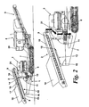
Figure 3 is a side view of a mobile crushing machine which illustrates the invention and the bypass mechanism, and shows the machine in a transport position; -
Figure 4 is similar toFigure 3 , but shows the machine in an operating position; and -
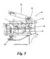
Figure 5 shows a detail of the machine ofFigures 3 and 4 . - The machine of
Figure 1 is a mobile crushing machine for crushing stone, aggregate and the like. The machine comprises abase 1, on which are mounted afeed conveyor 2, crushing means 3, a power unit 4 including a control unit, and amain conveyor 5. - The
base 1 hastracks 6 and anelongate platform 7 on which the other parts are mounted, with thefeed conveyor 2 at the rear end, and themain conveyor 5 at the front end. - The
feed conveyor 2 is of a known design, having aframe 8 for apowered belt 9 and afeed chute 10 at the rear end of thebelt 9 to receive material to be crushed. - The
frame 8 is mounted on theplatform 7 by two pairs of hydraulic piston andcylinder assemblies assemblies 11 act vertically to raise and lower the forward end of theframe 8, with thecylinders 13 being attached to theplatform 7, and thepistons 14 pivotally mounted to theframe 8. Theassemblies 12 act to move theframe 8 in the longitudinal direction between the normal operating position ofFigure 1 , and a bypass position ofFigure 2 . Thecylinders 15 are pivotally attached to anupstand 16 on theplatform 7, while thepistons 17 are connected to anabutment 18 on the underside of theframe 8. The piston andcylinder assemblies feed conveyor 2 also carries ametal detector 19, mounted near the forward end of the belt, and adapted to send a signal to the control unit when metal is detected in the material on thefeed conveyor 2. - The crushing means 3 comprises a cone crusher of known design, which need not be described further here. Material fed into the top of the
crusher 3 from the forward end of thefeed conveyor 2 is crushed, and falls out of the bottom of thecrusher 3 onto themain conveyor 5. - The
main conveyor 5, mounted on the front end of theplatform 7, is also of a known design, and will not be described further here. - The power and control unit 4 is also mounted near the front end of the
platform 7, and includes a diesel engine (not shown) as the power source for the machine, an hydraulic system (not shown) for operating the piston andcylinder assemblies control area 20 for the machine operator. The controls include manual controls and electronic controls for automatically performing some operations. - A
bypass chute 21 is mounted on theplatform 7 between thefeed conveyor 2 and thecrusher 3. Material fed into the top of thechute 21 will not fall onto themain conveyor 5, but instead will be discharged to the side of the machine, to fall onto the ground, or into a suitable container. -
Figure 1 shows the machine in its normal operating position. - The
feed conveyor 2 is raised by means of theassemblies 11, and thepistons 17 of theassemblies 12 are extended, so that theconveyor 2 is ready to discharge into thecrusher 3. Then, in operation, material placed in thefeed chute 10 is carried upwards by thefeed conveyor 2, and discharged into thecrusher 3. The crushed material falls out of the bottom of thecrusher 3 onto themain conveyor 5, and is discharged at the forward end of that conveyor into a suitable container. The operator controls theconveyors crusher 3 from thecontrol area 20. - If the metal detector detects the presence of metal in the material on the
feed conveyor 2, it sends a signal to the electronic controls, which operate to stop thefeed conveyor 2. The operator then actuates theassemblies 12, to retract thepistons 17, causing thefeed conveyor 2 to move rearwardly into the bypass position shown inFigure 2 , where the material on the feed conveyor is discharged into thebypass chute 21, rather than thecrusher 3. The operator then starts thefeed conveyor 2 again, so that the material including the metal is discharged into the bypass chute to fall on the ground at the side of the machine. Once the operator is satisfied that the metal is no longer on thebelt 9, he stops theconveyor 2 and actuates theassemblies 12 to extend thepistons 17 again, thus moving thefeed conveyor 2 back into the normal operating position. Thefeed conveyor 2 can then be restarted, and normal operation resumed. - It will be appreciated that the machine is therefore able to deal with metal in the material quickly and easily, and without the operator needing to leave the
control area 20. -
Figure 3 shows the machine ofFigure 1 in a position in which it can be transported on a low loader or the like, and also illustrates the second aspect of the invention. In relation to the first aspect of the invention, however, it will be noted that for transport, thefeed conveyor 2 is in the bypass position. - The additional component of the machine shown in
Figures 3 and 4 is ascreening unit 30. The remainder of the machine is as shown inFigure 1 , and corresponding reference numerals have been applied to corresponding parts. Only thescreening unit 30 will now be described. - The
screening unit 30 is mounted on theplatform 7 between thecrusher 3 and thecontrol area 20. It comprises arectangular frame 31 that carries a vibratingmesh screen 32 and ascreen conveyor 33. Thescreen 32 is removably mounted in theframe 31, since different sizes of mesh may be needed to screen different materials. Thescreen conveyor 33 is located above thescreen 32, and is mounted on theframe 31 by a pair of piston andcylinder assemblies 34. This is best seen inFigure 5 , which shows the detail of thescreening unit 30. The cylinders of theassemblies 34 are attached to theframe 31, while the pistons are pivotally attached to thescreen conveyor 33. Actuation of theassemblies 34 enables the angle of thescreen conveyor 33 to be adjusted relative to thescreen 32, to facilitate changing of thescreen 32. - The
screening unit 30 also has achute 35, as shown inFigure 4 , for directing material passing through thescreen 32 onto themain conveyor 5. - The
frame 31 is mounted on theplatform 7 by two further pairs of piston andcylinder assemblies pair 36 is at the rear end of theframe 31, and acts vertically. Thecylinders 38 of theassemblies 36 are attached to theplatform 7, while the piston 39 is pivotally attached to aprojection 40 at the rear of theframe 31. Theassemblies 37 act at an angle on the front end of theframe 31. Thecylinders 41 of theassemblies 37 are attached pivotally to astep 42 on theplatform 7, and thepistons 43 are pivotally attached to the front end of theframe 31. - In
Figure 3 thescreening unit 30 is in a horizontal position, for ease of transportation.Figure 4 shows the machine in its normal operating position, with thescreening unit 30 raised by theassemblies assemblies 34 extended to raise thescreen conveyor 33 relative to thescreen 32. Thescreening unit 30 is then at an angle to the horizontal. The rear end of thescreen conveyor 33 is below the discharge point of thefeed conveyor 2, while the discharge point at the front end is above the end of thescreen 32. The rear, lower end of thescreen 32 is above the top of thecrusher 3. - Thus, in operation, material discharged from the
feed conveyor 2 falls onto thescreen conveyor 33, which in turn discharges it onto the vibratingscreen 32. The finer material passes through thescreen 32 and falls through thechute 35 onto themain conveyor 5, while the coarser material, which does not pass through thescreen 32, slides or rolls down thescreen 32 and into thecrusher 3, crushed material, as in the embodiment forFigure 1 , then falls onto themain conveyor 5. -
Figure 5 shows how thescreen 32 is changed. For this, with thescreening unit 30 in its inoperative position, the operator actuates theassemblies 34 to extend the pistons, causing thescreen conveyor 33 to be raised as shown. The operator can then easily reach thescreen 32 to remove it and to insert a different screen. Theassemblies 34 are then actuated to lower thescreen conveyor 33 again, returning theunit 30 to its inoperative position. - The advantage of the
screening unit 30 is that it limits the proportion of finer material that passes through thecrusher 3, which then operates more efficiently. It will be appreciated that the advantages of including thescreening unit 30 on the machine, rather than using a separate screening unit, are that capital and running costs (including transport costs) are reduced, as is set-up time. The time needed to change a screen is also minimised. - Clearly, the invention and the bypass aspect may be used independently. If they are both incorporated in one machine it will increase efficiency accordingly.
Claims (9)
- A mobile aggregate crushing machine comprising a feed conveyor (2), a screening unit (30), a crushing means (3) and a main conveyor (5), the screening unit (30) comprising a screen (32) that vibrates when operative, and comprising a frame (31) on which the screen (32) is mounted, characterised by the frame (31) being movable between an inoperative position in which the frame (31) is substantially horizontal, and an operative position in which the frame (31) is angled relative to the horizontal, the arrangement of the machine being such that the screening unit (30) is arranged on the opposite side of the crushing means (3) relative to the feed conveyor (2) and material comprising aggregate to be crushed is, in use, fed from the feed conveyor (2) to the screening unit (30) for separation, so that finer material will be passed onto the main conveyor (5) without passing through the crushing means (3), and coarser material will be discharged from the screening unit into the crushing means (3) and will fall from the crushing means onto the main conveyor (5).
- A machine according to claim 1, wherein the screening unit (30) comprises a screen conveyor (33) and a screen (32) that vibrates when operative.
- A machine according to claim 2, wherein the feed conveyor (2) is arranged to pass the material to the screen conveyor (33) and onto the screen(32).
- A machine according to any preceding claim in which the crushing means (3) is a cone crusher.
- A machine according to any preceding claim, in which the aggregate crushing machine is suitable for crushing aggregate comprising at least one of material from a quarry and demolition waste.
- A machine according to claim 1, 2 or 3 wherein the screen (32) can be changed when the screening unit (30) is in the inoperative position.
- A machine according to claim 6 wherein the screening unit (30) is mounted on the frame (31) by at least one pair of piston and cylinder assemblies (34, 36, 37).
- A machine according to claim 7 as dependent on claim 6 depending from claim 2 or claim 3 wherein the cylinder assemblies (34, 36, 37) can be actuated to adjust an angle of the screen conveyor (33) relative to the screen (32) to facilitate changing of the screen (32) when the screening unit (30) is in the inoperative position.
- A machine according to claim 1 wherein the aggregate crushing machine further comprises a bypass chute (21) for the crushing means (3) and wherein the feed conveyor (2) is longitudinally moveable between a normal operating position in which the material is fed to the crushing means and a bypass position in which the material is fed to the bypass chute, the arrangement of the machine being such that on detection of metal in the material the feed conveyor (2) is equipped to be stopped and moved longitudinally from the normal operating position to the bypass position so that the material with the metal can be discharged into the bypass chute (21).
Priority Applications (1)
| Application Number | Priority Date | Filing Date | Title |
|---|---|---|---|
| EP14152199.7A EP2724782B1 (en) | 2007-04-21 | 2008-04-21 | Crushing machines |
Applications Claiming Priority (2)
| Application Number | Priority Date | Filing Date | Title |
|---|---|---|---|
| GBGB0707761.3A GB0707761D0 (en) | 2007-04-21 | 2007-04-21 | Crushing machines |
| PCT/GB2008/001396 WO2008129287A2 (en) | 2007-04-21 | 2008-04-21 | Crushing machines |
Related Child Applications (2)
| Application Number | Title | Priority Date | Filing Date |
|---|---|---|---|
| EP14152199.7A Division-Into EP2724782B1 (en) | 2007-04-21 | 2008-04-21 | Crushing machines |
| EP14152199.7A Division EP2724782B1 (en) | 2007-04-21 | 2008-04-21 | Crushing machines |
Publications (2)
| Publication Number | Publication Date |
|---|---|
| EP2152427A2 EP2152427A2 (en) | 2010-02-17 |
| EP2152427B1 true EP2152427B1 (en) | 2015-07-01 |
Family
ID=38135222
Family Applications (2)
| Application Number | Title | Priority Date | Filing Date |
|---|---|---|---|
| EP08750474.2A Active EP2152427B1 (en) | 2007-04-21 | 2008-04-21 | Crushing machines |
| EP14152199.7A Active EP2724782B1 (en) | 2007-04-21 | 2008-04-21 | Crushing machines |
Family Applications After (1)
| Application Number | Title | Priority Date | Filing Date |
|---|---|---|---|
| EP14152199.7A Active EP2724782B1 (en) | 2007-04-21 | 2008-04-21 | Crushing machines |
Country Status (5)
| Country | Link |
|---|---|
| US (3) | US8469298B2 (en) |
| EP (2) | EP2152427B1 (en) |
| AU (1) | AU2008240460B2 (en) |
| GB (1) | GB0707761D0 (en) |
| WO (1) | WO2008129287A2 (en) |
Families Citing this family (26)
| Publication number | Priority date | Publication date | Assignee | Title |
|---|---|---|---|---|
| CA2813487C (en) | 2011-01-14 | 2016-03-01 | Shred-Tech Corporation | Shredding recyclable material containing information |
| AT13322U1 (en) * | 2012-01-05 | 2013-10-15 | Kormann Rockster Recycler Gmbh | DEVICE FOR CRIMINALIZING PIECES OF GOOD |
| US9186681B2 (en) | 2012-12-10 | 2015-11-17 | Screen Machine Industries Llc | Apparatus for sizing and separating particulate material |
| ES2488040B1 (en) * | 2013-01-23 | 2015-06-11 | Talleres Zb, S.A. | Mobile metal fragmenting machine |
| GB2510839B (en) * | 2013-02-14 | 2017-11-01 | Terex Gb Ltd | Material Processing Apparatus with Multi-mode Feed Conveyor Assembly |
| EP2837585B1 (en) * | 2013-08-14 | 2015-12-30 | Sandvik Intellectual Property AB | Main frame for mobile bulk processing apparatus |
| RU2641156C2 (en) * | 2013-09-04 | 2018-01-16 | Метсо Минералз, Инк. | Processing plant for mineral material processing and method for operating such plant |
| EP3041610B1 (en) * | 2013-09-04 | 2017-08-16 | Metso Minerals, Inc. | A mineral material processing plant and a method for operating a processing plant |
| JP5771349B1 (en) * | 2014-08-25 | 2015-08-26 | 株式会社小松製作所 | Self-propelled recycling machine |
| US20160107166A1 (en) * | 2014-10-20 | 2016-04-21 | Imperial Technologies, Inc. | Self contained coal processing unit |
| US9845715B2 (en) | 2015-01-07 | 2017-12-19 | Komatsu Ltd. | Mobile recycler |
| US10576477B2 (en) * | 2015-03-24 | 2020-03-03 | Terex Usa, Llc | Material processing plant |
| US20180161779A1 (en) * | 2015-05-29 | 2018-06-14 | Smoracy, Llc | Discharge System for a Waste Processing Machine and Method Thereof |
| DE102017112091A1 (en) * | 2017-06-01 | 2018-12-06 | Kleemann Gmbh | processing plant |
| US10589285B2 (en) | 2017-07-10 | 2020-03-17 | Joy Global Underground Mining Llc | Feeder breaker with reduced fines generation |
| US10730055B2 (en) * | 2017-09-20 | 2020-08-04 | Johnson Crushers International, Inc. | Method of use of aggregate processing equipment |
| GB2575881B (en) | 2018-07-27 | 2021-02-24 | Terex Gb Ltd | Clamping tool for a jaw crusher |
| CN108894271B (en) * | 2018-08-13 | 2024-03-05 | 徐州徐工矿业机械有限公司 | An automatic disassembly type inspection and screening system, method and mobile crushing and screening station |
| CA3174528A1 (en) * | 2020-04-20 | 2021-10-28 | Sandvik Ltd | Screening assembly for a mobile bulk material processing apparatus |
| US12032363B2 (en) * | 2020-11-17 | 2024-07-09 | Terex Usa, Llc | Method and apparatus for reconfiguring a material processing plant |
| EP4260940A1 (en) * | 2022-04-13 | 2023-10-18 | Reason Panoply, LDA | Portable system for crushing construction and demolition waste and use thereof |
| GB2609081C (en) * | 2022-05-23 | 2023-08-16 | Portafill International Ltd | Mobile aggregate processing plant |
| DE102022118032B3 (en) * | 2022-07-19 | 2023-08-10 | Kleemann Gmbh | Mobile rock processing device with improved scheduling of a discontinuous material feed |
| EP4357024A1 (en) * | 2022-10-18 | 2024-04-24 | Sandvik Ltd | A mobile bulk material processing apparatus |
| FI131273B1 (en) * | 2024-01-19 | 2025-01-21 | Metso Finland Oy | Maintenance access to pre-screen media at mobile plants |
| US20250289000A1 (en) * | 2024-03-15 | 2025-09-18 | McCloskey International Limited | Continuous feed cone crusher protection system and method |
Citations (4)
| Publication number | Priority date | Publication date | Assignee | Title |
|---|---|---|---|---|
| US4383651A (en) * | 1980-10-20 | 1983-05-17 | Allis-Chalmers Corporation | Portable crushing and screening plant |
| EP0301798A1 (en) * | 1987-07-31 | 1989-02-01 | EXTEC SCREENS & CRUSHERS LIMITED | Screening apparatus with tiltable vibratory screen |
| EP0382922A2 (en) * | 1989-02-15 | 1990-08-22 | Westfalia Becorit Industrietechnik GmbH | Mobile crusher, especially for comminuting demolition materials and other rubble |
| US20030146315A1 (en) * | 2002-02-06 | 2003-08-07 | Ian Boast | Screen assembly |
Family Cites Families (17)
| Publication number | Priority date | Publication date | Assignee | Title |
|---|---|---|---|---|
| US3226043A (en) * | 1963-04-15 | 1965-12-28 | Goodman Mfg Co | Crushing apparatus |
| US3647150A (en) * | 1969-08-27 | 1972-03-07 | Pettibone Corp | Crusher |
| US3963181A (en) * | 1975-05-19 | 1976-06-15 | Nabisco, Inc. | Food reclaiming system |
| US4598875A (en) * | 1978-09-11 | 1986-07-08 | Allis-Chalmers Corporation | Portable crushing and screening plant |
| US4478372A (en) * | 1979-03-15 | 1984-10-23 | Raytheon Company | Bypass feed apparatus |
| US4655402A (en) * | 1982-01-07 | 1987-04-07 | Bernard Desourdy | Portable crushing plant |
| US5074435A (en) * | 1990-06-01 | 1991-12-24 | Don Suverkrop, Inc. | System for controlling the feed rate of a vibrating feeder |
| US5263651A (en) * | 1992-04-01 | 1993-11-23 | Beloit Technologies, Inc. | Safety device for chip conditioning device |
| US5294065A (en) * | 1993-01-29 | 1994-03-15 | Portec, Inc. | Portable screening/dosing/mixing plant |
| US6626608B2 (en) * | 2000-10-16 | 2003-09-30 | Jerry Olynyk | Mobile rock crusher |
| FI109662B (en) * | 2001-08-31 | 2002-09-30 | Metso Minerals Tampere Oy | Transport locking arrangement for vibrating feeder of mobile crushing unit characterized in that downward rotatable sidewall of feeder hopper in its lower position is capable of locking vibrating feeder rigidly to framework of crushing unit |
| WO2005009990A1 (en) | 2003-07-25 | 2005-02-03 | Hetero Drugs Limited | Aripiprazole crystalline forms |
| GB0408594D0 (en) * | 2004-04-16 | 2004-05-19 | Extec Screens & Crushers Ltd | Crusher apparatus |
| US7264104B2 (en) * | 2005-03-11 | 2007-09-04 | Johnson Crushers International | Crusher in-feed conveyor method and apparatus |
| US9186681B2 (en) * | 2012-12-10 | 2015-11-17 | Screen Machine Industries Llc | Apparatus for sizing and separating particulate material |
| GB2515445B (en) * | 2013-01-18 | 2017-05-24 | Terex Gb Ltd | Material processing apparatus with deployable feed conveyor |
| GB2510839B (en) * | 2013-02-14 | 2017-11-01 | Terex Gb Ltd | Material Processing Apparatus with Multi-mode Feed Conveyor Assembly |
-
2007
- 2007-04-21 GB GBGB0707761.3A patent/GB0707761D0/en not_active Ceased
-
2008
- 2008-04-21 AU AU2008240460A patent/AU2008240460B2/en active Active
- 2008-04-21 EP EP08750474.2A patent/EP2152427B1/en active Active
- 2008-04-21 US US12/596,943 patent/US8469298B2/en active Active
- 2008-04-21 WO PCT/GB2008/001396 patent/WO2008129287A2/en not_active Ceased
- 2008-04-21 EP EP14152199.7A patent/EP2724782B1/en active Active
-
2013
- 2013-01-14 US US13/740,708 patent/US8905338B2/en active Active
-
2014
- 2014-11-25 US US14/553,660 patent/US10137457B2/en active Active
Patent Citations (4)
| Publication number | Priority date | Publication date | Assignee | Title |
|---|---|---|---|---|
| US4383651A (en) * | 1980-10-20 | 1983-05-17 | Allis-Chalmers Corporation | Portable crushing and screening plant |
| EP0301798A1 (en) * | 1987-07-31 | 1989-02-01 | EXTEC SCREENS & CRUSHERS LIMITED | Screening apparatus with tiltable vibratory screen |
| EP0382922A2 (en) * | 1989-02-15 | 1990-08-22 | Westfalia Becorit Industrietechnik GmbH | Mobile crusher, especially for comminuting demolition materials and other rubble |
| US20030146315A1 (en) * | 2002-02-06 | 2003-08-07 | Ian Boast | Screen assembly |
Also Published As
| Publication number | Publication date |
|---|---|
| WO2008129287A3 (en) | 2009-01-15 |
| EP2724782A1 (en) | 2014-04-30 |
| EP2724782B1 (en) | 2015-06-03 |
| AU2008240460B2 (en) | 2012-04-19 |
| GB0707761D0 (en) | 2007-05-30 |
| US8905338B2 (en) | 2014-12-09 |
| US20130126648A1 (en) | 2013-05-23 |
| US20150076264A1 (en) | 2015-03-19 |
| US8469298B2 (en) | 2013-06-25 |
| WO2008129287A2 (en) | 2008-10-30 |
| EP2152427A2 (en) | 2010-02-17 |
| US20100193619A1 (en) | 2010-08-05 |
| AU2008240460A1 (en) | 2008-10-30 |
| US10137457B2 (en) | 2018-11-27 |
Similar Documents
| Publication | Publication Date | Title |
|---|---|---|
| EP2724782B1 (en) | Crushing machines | |
| AU2018202149B2 (en) | A Transfer Conveyor Assembly For a Screening Apparatus | |
| US6935587B2 (en) | Mobile rock crushing plant | |
| EP3041612B1 (en) | A mineral material processing plant and a method for operating a processing plant | |
| EP3041610B1 (en) | A mineral material processing plant and a method for operating a processing plant | |
| AU2011205197B2 (en) | Crushing machines | |
| US7806353B2 (en) | Crusher apparatus | |
| WO2001034314A1 (en) | Mobile material handling apparatus with lowerable track set | |
| CA3139567A1 (en) | Method and apparatus for reconfiguring a material processing plant | |
| US12103041B2 (en) | Portable screening and stockpiling apparatus | |
| RU2228796C2 (en) | Mobile line for grading and roentgenoradiometric separation of ores and technogenic raw materials | |
| CN120861245A (en) | Crushing plant for processing inert materials with mobile loading unit | |
| IE20050413U1 (en) | A material screening apparatus |
Legal Events
| Date | Code | Title | Description |
|---|---|---|---|
| PUAI | Public reference made under article 153(3) epc to a published international application that has entered the european phase |
Free format text: ORIGINAL CODE: 0009012 |
|
| 17P | Request for examination filed |
Effective date: 20091120 |
|
| AK | Designated contracting states |
Kind code of ref document: A2 Designated state(s): AT BE BG CH CY CZ DE DK EE ES FI FR GB GR HR HU IE IS IT LI LT LU LV MC MT NL NO PL PT RO SE SI SK TR |
|
| AX | Request for extension of the european patent |
Extension state: AL BA MK RS |
|
| RAP1 | Party data changed (applicant data changed or rights of an application transferred) |
Owner name: TEREX CORPORATION |
|
| RAP1 | Party data changed (applicant data changed or rights of an application transferred) |
Owner name: TEREX GB LTD. |
|
| DAX | Request for extension of the european patent (deleted) | ||
| 17Q | First examination report despatched |
Effective date: 20120720 |
|
| GRAP | Despatch of communication of intention to grant a patent |
Free format text: ORIGINAL CODE: EPIDOSNIGR1 |
|
| INTG | Intention to grant announced |
Effective date: 20141113 |
|
| GRAS | Grant fee paid |
Free format text: ORIGINAL CODE: EPIDOSNIGR3 |
|
| GRAA | (expected) grant |
Free format text: ORIGINAL CODE: 0009210 |
|
| AK | Designated contracting states |
Kind code of ref document: B1 Designated state(s): AT BE BG CH CY CZ DE DK EE ES FI FR GB GR HR HU IE IS IT LI LT LU LV MC MT NL NO PL PT RO SE SI SK TR |
|
| REG | Reference to a national code |
Ref country code: GB Ref legal event code: FG4D |
|
| REG | Reference to a national code |
Ref country code: AT Ref legal event code: REF Ref document number: 733629 Country of ref document: AT Kind code of ref document: T Effective date: 20150715 Ref country code: CH Ref legal event code: EP |
|
| REG | Reference to a national code |
Ref country code: SE Ref legal event code: TRGR |
|
| REG | Reference to a national code |
Ref country code: IE Ref legal event code: FG4D |
|
| REG | Reference to a national code |
Ref country code: DE Ref legal event code: R096 Ref document number: 602008038792 Country of ref document: DE |
|
| REG | Reference to a national code |
Ref country code: AT Ref legal event code: MK05 Ref document number: 733629 Country of ref document: AT Kind code of ref document: T Effective date: 20150701 |
|
| REG | Reference to a national code |
Ref country code: NL Ref legal event code: MP Effective date: 20150701 |
|
| REG | Reference to a national code |
Ref country code: LT Ref legal event code: MG4D |
|
| PG25 | Lapsed in a contracting state [announced via postgrant information from national office to epo] |
Ref country code: GR Free format text: LAPSE BECAUSE OF FAILURE TO SUBMIT A TRANSLATION OF THE DESCRIPTION OR TO PAY THE FEE WITHIN THE PRESCRIBED TIME-LIMIT Effective date: 20151002 Ref country code: NO Free format text: LAPSE BECAUSE OF FAILURE TO SUBMIT A TRANSLATION OF THE DESCRIPTION OR TO PAY THE FEE WITHIN THE PRESCRIBED TIME-LIMIT Effective date: 20151001 Ref country code: LT Free format text: LAPSE BECAUSE OF FAILURE TO SUBMIT A TRANSLATION OF THE DESCRIPTION OR TO PAY THE FEE WITHIN THE PRESCRIBED TIME-LIMIT Effective date: 20150701 Ref country code: LV Free format text: LAPSE BECAUSE OF FAILURE TO SUBMIT A TRANSLATION OF THE DESCRIPTION OR TO PAY THE FEE WITHIN THE PRESCRIBED TIME-LIMIT Effective date: 20150701 |
|
| PG25 | Lapsed in a contracting state [announced via postgrant information from national office to epo] |
Ref country code: IS Free format text: LAPSE BECAUSE OF FAILURE TO SUBMIT A TRANSLATION OF THE DESCRIPTION OR TO PAY THE FEE WITHIN THE PRESCRIBED TIME-LIMIT Effective date: 20151101 Ref country code: HR Free format text: LAPSE BECAUSE OF FAILURE TO SUBMIT A TRANSLATION OF THE DESCRIPTION OR TO PAY THE FEE WITHIN THE PRESCRIBED TIME-LIMIT Effective date: 20150701 Ref country code: AT Free format text: LAPSE BECAUSE OF FAILURE TO SUBMIT A TRANSLATION OF THE DESCRIPTION OR TO PAY THE FEE WITHIN THE PRESCRIBED TIME-LIMIT Effective date: 20150701 Ref country code: PL Free format text: LAPSE BECAUSE OF FAILURE TO SUBMIT A TRANSLATION OF THE DESCRIPTION OR TO PAY THE FEE WITHIN THE PRESCRIBED TIME-LIMIT Effective date: 20150701 Ref country code: PT Free format text: LAPSE BECAUSE OF FAILURE TO SUBMIT A TRANSLATION OF THE DESCRIPTION OR TO PAY THE FEE WITHIN THE PRESCRIBED TIME-LIMIT Effective date: 20151102 Ref country code: ES Free format text: LAPSE BECAUSE OF FAILURE TO SUBMIT A TRANSLATION OF THE DESCRIPTION OR TO PAY THE FEE WITHIN THE PRESCRIBED TIME-LIMIT Effective date: 20150701 |
|
| REG | Reference to a national code |
Ref country code: DE Ref legal event code: R097 Ref document number: 602008038792 Country of ref document: DE |
|
| PG25 | Lapsed in a contracting state [announced via postgrant information from national office to epo] |
Ref country code: SK Free format text: LAPSE BECAUSE OF FAILURE TO SUBMIT A TRANSLATION OF THE DESCRIPTION OR TO PAY THE FEE WITHIN THE PRESCRIBED TIME-LIMIT Effective date: 20150701 Ref country code: CZ Free format text: LAPSE BECAUSE OF FAILURE TO SUBMIT A TRANSLATION OF THE DESCRIPTION OR TO PAY THE FEE WITHIN THE PRESCRIBED TIME-LIMIT Effective date: 20150701 Ref country code: EE Free format text: LAPSE BECAUSE OF FAILURE TO SUBMIT A TRANSLATION OF THE DESCRIPTION OR TO PAY THE FEE WITHIN THE PRESCRIBED TIME-LIMIT Effective date: 20150701 Ref country code: DK Free format text: LAPSE BECAUSE OF FAILURE TO SUBMIT A TRANSLATION OF THE DESCRIPTION OR TO PAY THE FEE WITHIN THE PRESCRIBED TIME-LIMIT Effective date: 20150701 Ref country code: IT Free format text: LAPSE BECAUSE OF FAILURE TO SUBMIT A TRANSLATION OF THE DESCRIPTION OR TO PAY THE FEE WITHIN THE PRESCRIBED TIME-LIMIT Effective date: 20150701 |
|
| PLBE | No opposition filed within time limit |
Free format text: ORIGINAL CODE: 0009261 |
|
| STAA | Information on the status of an ep patent application or granted ep patent |
Free format text: STATUS: NO OPPOSITION FILED WITHIN TIME LIMIT |
|
| PG25 | Lapsed in a contracting state [announced via postgrant information from national office to epo] |
Ref country code: RO Free format text: LAPSE BECAUSE OF FAILURE TO SUBMIT A TRANSLATION OF THE DESCRIPTION OR TO PAY THE FEE WITHIN THE PRESCRIBED TIME-LIMIT Effective date: 20150701 |
|
| 26N | No opposition filed |
Effective date: 20160404 |
|
| PG25 | Lapsed in a contracting state [announced via postgrant information from national office to epo] |
Ref country code: BE Free format text: LAPSE BECAUSE OF NON-PAYMENT OF DUE FEES Effective date: 20160430 Ref country code: SI Free format text: LAPSE BECAUSE OF FAILURE TO SUBMIT A TRANSLATION OF THE DESCRIPTION OR TO PAY THE FEE WITHIN THE PRESCRIBED TIME-LIMIT Effective date: 20150701 |
|
| REG | Reference to a national code |
Ref country code: CH Ref legal event code: PL |
|
| PG25 | Lapsed in a contracting state [announced via postgrant information from national office to epo] |
Ref country code: BE Free format text: LAPSE BECAUSE OF FAILURE TO SUBMIT A TRANSLATION OF THE DESCRIPTION OR TO PAY THE FEE WITHIN THE PRESCRIBED TIME-LIMIT Effective date: 20150701 Ref country code: LU Free format text: LAPSE BECAUSE OF FAILURE TO SUBMIT A TRANSLATION OF THE DESCRIPTION OR TO PAY THE FEE WITHIN THE PRESCRIBED TIME-LIMIT Effective date: 20160421 |
|
| REG | Reference to a national code |
Ref country code: IE Ref legal event code: MM4A |
|
| REG | Reference to a national code |
Ref country code: FR Ref legal event code: ST Effective date: 20161230 |
|
| PG25 | Lapsed in a contracting state [announced via postgrant information from national office to epo] |
Ref country code: LI Free format text: LAPSE BECAUSE OF NON-PAYMENT OF DUE FEES Effective date: 20160430 Ref country code: CH Free format text: LAPSE BECAUSE OF NON-PAYMENT OF DUE FEES Effective date: 20160430 Ref country code: FR Free format text: LAPSE BECAUSE OF NON-PAYMENT OF DUE FEES Effective date: 20160502 |
|
| PG25 | Lapsed in a contracting state [announced via postgrant information from national office to epo] |
Ref country code: IE Free format text: LAPSE BECAUSE OF NON-PAYMENT OF DUE FEES Effective date: 20160421 |
|
| PG25 | Lapsed in a contracting state [announced via postgrant information from national office to epo] |
Ref country code: NL Free format text: LAPSE BECAUSE OF FAILURE TO SUBMIT A TRANSLATION OF THE DESCRIPTION OR TO PAY THE FEE WITHIN THE PRESCRIBED TIME-LIMIT Effective date: 20150701 |
|
| PG25 | Lapsed in a contracting state [announced via postgrant information from national office to epo] |
Ref country code: HU Free format text: LAPSE BECAUSE OF FAILURE TO SUBMIT A TRANSLATION OF THE DESCRIPTION OR TO PAY THE FEE WITHIN THE PRESCRIBED TIME-LIMIT; INVALID AB INITIO Effective date: 20080421 Ref country code: CY Free format text: LAPSE BECAUSE OF FAILURE TO SUBMIT A TRANSLATION OF THE DESCRIPTION OR TO PAY THE FEE WITHIN THE PRESCRIBED TIME-LIMIT Effective date: 20150701 |
|
| PG25 | Lapsed in a contracting state [announced via postgrant information from national office to epo] |
Ref country code: TR Free format text: LAPSE BECAUSE OF FAILURE TO SUBMIT A TRANSLATION OF THE DESCRIPTION OR TO PAY THE FEE WITHIN THE PRESCRIBED TIME-LIMIT Effective date: 20150701 Ref country code: MC Free format text: LAPSE BECAUSE OF FAILURE TO SUBMIT A TRANSLATION OF THE DESCRIPTION OR TO PAY THE FEE WITHIN THE PRESCRIBED TIME-LIMIT Effective date: 20150701 Ref country code: MT Free format text: LAPSE BECAUSE OF NON-PAYMENT OF DUE FEES Effective date: 20160430 |
|
| PG25 | Lapsed in a contracting state [announced via postgrant information from national office to epo] |
Ref country code: BG Free format text: LAPSE BECAUSE OF FAILURE TO SUBMIT A TRANSLATION OF THE DESCRIPTION OR TO PAY THE FEE WITHIN THE PRESCRIBED TIME-LIMIT Effective date: 20150701 |
|
| P01 | Opt-out of the competence of the unified patent court (upc) registered |
Effective date: 20230530 |
|
| PGFP | Annual fee paid to national office [announced via postgrant information from national office to epo] |
Ref country code: FI Payment date: 20250424 Year of fee payment: 18 |
|
| PGFP | Annual fee paid to national office [announced via postgrant information from national office to epo] |
Ref country code: DE Payment date: 20250422 Year of fee payment: 18 |
|
| PGFP | Annual fee paid to national office [announced via postgrant information from national office to epo] |
Ref country code: GB Payment date: 20250423 Year of fee payment: 18 |
|
| PGFP | Annual fee paid to national office [announced via postgrant information from national office to epo] |
Ref country code: SE Payment date: 20250429 Year of fee payment: 18 |