EP2152403B1 - Separation media and apparatus - Google Patents
Separation media and apparatus Download PDFInfo
- Publication number
- EP2152403B1 EP2152403B1 EP08747685.9A EP08747685A EP2152403B1 EP 2152403 B1 EP2152403 B1 EP 2152403B1 EP 08747685 A EP08747685 A EP 08747685A EP 2152403 B1 EP2152403 B1 EP 2152403B1
- Authority
- EP
- European Patent Office
- Prior art keywords
- particles
- separation media
- separation
- tubular member
- moieties
- Prior art date
- Legal status (The legal status is an assumption and is not a legal conclusion. Google has not performed a legal analysis and makes no representation as to the accuracy of the status listed.)
- Active
Links
- 238000000926 separation method Methods 0.000 title claims description 68
- 239000002245 particle Substances 0.000 claims description 95
- 239000000463 material Substances 0.000 claims description 43
- 239000000203 mixture Substances 0.000 claims description 34
- 229910003460 diamond Inorganic materials 0.000 claims description 24
- 239000010432 diamond Substances 0.000 claims description 24
- VYPSYNLAJGMNEJ-UHFFFAOYSA-N Silicium dioxide Chemical compound O=[Si]=O VYPSYNLAJGMNEJ-UHFFFAOYSA-N 0.000 claims description 17
- 238000013375 chromatographic separation Methods 0.000 claims description 12
- 239000012530 fluid Substances 0.000 claims description 9
- 229920000642 polymer Polymers 0.000 claims description 9
- OKTJSMMVPCPJKN-UHFFFAOYSA-N Carbon Chemical compound [C] OKTJSMMVPCPJKN-UHFFFAOYSA-N 0.000 claims description 7
- 229910002804 graphite Inorganic materials 0.000 claims description 7
- 239000010439 graphite Substances 0.000 claims description 7
- 239000000377 silicon dioxide Substances 0.000 claims description 7
- 125000003118 aryl group Chemical group 0.000 claims description 6
- 125000002947 alkylene group Chemical group 0.000 claims description 5
- 125000004419 alkynylene group Chemical group 0.000 claims description 5
- 125000000732 arylene group Chemical group 0.000 claims description 5
- 229910052681 coesite Inorganic materials 0.000 claims description 4
- 229910052906 cristobalite Inorganic materials 0.000 claims description 4
- 229910052682 stishovite Inorganic materials 0.000 claims description 4
- 229910052905 tridymite Inorganic materials 0.000 claims description 4
- KXDHJXZQYSOELW-UHFFFAOYSA-N Carbamic acid Chemical group NC(O)=O KXDHJXZQYSOELW-UHFFFAOYSA-N 0.000 claims description 3
- 125000001931 aliphatic group Chemical group 0.000 claims description 3
- 125000000217 alkyl group Chemical group 0.000 claims description 3
- 238000001816 cooling Methods 0.000 claims description 3
- 239000001257 hydrogen Substances 0.000 claims description 3
- 229910052739 hydrogen Inorganic materials 0.000 claims description 3
- 125000004435 hydrogen atom Chemical group [H]* 0.000 claims description 3
- 125000001997 phenyl group Chemical group [H]C1=C([H])C([H])=C(*)C([H])=C1[H] 0.000 claims description 3
- XUIMIQQOPSSXEZ-UHFFFAOYSA-N Silicon Chemical group [Si] XUIMIQQOPSSXEZ-UHFFFAOYSA-N 0.000 claims description 2
- 238000000576 coating method Methods 0.000 description 18
- 239000011248 coating agent Substances 0.000 description 16
- 238000000034 method Methods 0.000 description 13
- 238000004128 high performance liquid chromatography Methods 0.000 description 9
- 239000000758 substrate Substances 0.000 description 7
- 239000007853 buffer solution Substances 0.000 description 6
- 239000003643 water by type Substances 0.000 description 6
- 238000010521 absorption reaction Methods 0.000 description 5
- 239000000470 constituent Substances 0.000 description 5
- 238000004458 analytical method Methods 0.000 description 4
- 239000013626 chemical specie Substances 0.000 description 4
- 230000014759 maintenance of location Effects 0.000 description 4
- 238000004704 ultra performance liquid chromatography Methods 0.000 description 4
- UHOVQNZJYSORNB-UHFFFAOYSA-N Benzene Chemical compound C1=CC=CC=C1 UHOVQNZJYSORNB-UHFFFAOYSA-N 0.000 description 3
- WSNMPAVSZJSIMT-UHFFFAOYSA-N COc1c(C)c2COC(=O)c2c(O)c1CC(O)C1(C)CCC(=O)O1 Chemical compound COc1c(C)c2COC(=O)c2c(O)c1CC(O)C1(C)CCC(=O)O1 WSNMPAVSZJSIMT-UHFFFAOYSA-N 0.000 description 3
- YXFVVABEGXRONW-UHFFFAOYSA-N Toluene Chemical compound CC1=CC=CC=C1 YXFVVABEGXRONW-UHFFFAOYSA-N 0.000 description 3
- 238000004587 chromatography analysis Methods 0.000 description 3
- 238000002347 injection Methods 0.000 description 3
- 239000007924 injection Substances 0.000 description 3
- 230000000717 retained effect Effects 0.000 description 3
- 229910001220 stainless steel Inorganic materials 0.000 description 3
- 239000010935 stainless steel Substances 0.000 description 3
- 230000005526 G1 to G0 transition Effects 0.000 description 2
- UXMQORVHJMUQFD-UHFFFAOYSA-N Heptanophenone Chemical compound CCCCCCC(=O)C1=CC=CC=C1 UXMQORVHJMUQFD-UHFFFAOYSA-N 0.000 description 2
- UFWIBTONFRDIAS-UHFFFAOYSA-N Naphthalene Chemical compound C1=CC=CC2=CC=CC=C21 UFWIBTONFRDIAS-UHFFFAOYSA-N 0.000 description 2
- PWATWSYOIIXYMA-UHFFFAOYSA-N Pentylbenzene Chemical compound CCCCCC1=CC=CC=C1 PWATWSYOIIXYMA-UHFFFAOYSA-N 0.000 description 2
- 239000012080 ambient air Substances 0.000 description 2
- 238000005251 capillar electrophoresis Methods 0.000 description 2
- 238000005229 chemical vapour deposition Methods 0.000 description 2
- 230000001419 dependent effect Effects 0.000 description 2
- 230000001627 detrimental effect Effects 0.000 description 2
- 230000005684 electric field Effects 0.000 description 2
- 238000011209 electrochromatography Methods 0.000 description 2
- 238000002474 experimental method Methods 0.000 description 2
- 125000000524 functional group Chemical group 0.000 description 2
- 239000005350 fused silica glass Substances 0.000 description 2
- 239000007789 gas Substances 0.000 description 2
- 239000011521 glass Substances 0.000 description 2
- PCHJSUWPFVWCPO-UHFFFAOYSA-N gold Chemical compound [Au] PCHJSUWPFVWCPO-UHFFFAOYSA-N 0.000 description 2
- 229910052737 gold Inorganic materials 0.000 description 2
- 239000010931 gold Substances 0.000 description 2
- 238000010438 heat treatment Methods 0.000 description 2
- 230000001788 irregular Effects 0.000 description 2
- 239000007788 liquid Substances 0.000 description 2
- 239000011159 matrix material Substances 0.000 description 2
- 238000002156 mixing Methods 0.000 description 2
- 229920002401 polyacrylamide Polymers 0.000 description 2
- 102000004169 proteins and genes Human genes 0.000 description 2
- 108090000623 proteins and genes Proteins 0.000 description 2
- 239000007787 solid Substances 0.000 description 2
- 238000012360 testing method Methods 0.000 description 2
- UMGDCJDMYOKAJW-UHFFFAOYSA-N thiourea Chemical compound NC(N)=S UMGDCJDMYOKAJW-UHFFFAOYSA-N 0.000 description 2
- XLYOFNOQVPJJNP-UHFFFAOYSA-N water Substances O XLYOFNOQVPJJNP-UHFFFAOYSA-N 0.000 description 2
- WEVYAHXRMPXWCK-UHFFFAOYSA-N Acetonitrile Chemical compound CC#N WEVYAHXRMPXWCK-UHFFFAOYSA-N 0.000 description 1
- RYGMFSIKBFXOCR-UHFFFAOYSA-N Copper Chemical compound [Cu] RYGMFSIKBFXOCR-UHFFFAOYSA-N 0.000 description 1
- 230000005679 Peltier effect Effects 0.000 description 1
- XSQUKJJJFZCRTK-UHFFFAOYSA-N Urea Natural products NC(N)=O XSQUKJJJFZCRTK-UHFFFAOYSA-N 0.000 description 1
- 238000002835 absorbance Methods 0.000 description 1
- CWRYPZZKDGJXCA-UHFFFAOYSA-N acenaphthene Chemical compound C1=CC(CC2)=C3C2=CC=CC3=C1 CWRYPZZKDGJXCA-UHFFFAOYSA-N 0.000 description 1
- 239000000654 additive Substances 0.000 description 1
- 239000003463 adsorbent Substances 0.000 description 1
- 239000003570 air Substances 0.000 description 1
- 239000000809 air pollutant Substances 0.000 description 1
- 231100001243 air pollutant Toxicity 0.000 description 1
- 239000012491 analyte Substances 0.000 description 1
- 239000011230 binding agent Substances 0.000 description 1
- 229910010293 ceramic material Inorganic materials 0.000 description 1
- 239000013043 chemical agent Substances 0.000 description 1
- 239000007795 chemical reaction product Substances 0.000 description 1
- 238000004891 communication Methods 0.000 description 1
- 229910052802 copper Inorganic materials 0.000 description 1
- 239000010949 copper Substances 0.000 description 1
- 238000000151 deposition Methods 0.000 description 1
- 230000001066 destructive effect Effects 0.000 description 1
- 238000001514 detection method Methods 0.000 description 1
- 238000009826 distribution Methods 0.000 description 1
- 230000000694 effects Effects 0.000 description 1
- 238000001962 electrophoresis Methods 0.000 description 1
- 239000003480 eluent Substances 0.000 description 1
- 238000010828 elution Methods 0.000 description 1
- 238000000105 evaporative light scattering detection Methods 0.000 description 1
- 239000000945 filler Substances 0.000 description 1
- 238000001502 gel electrophoresis Methods 0.000 description 1
- 239000003365 glass fiber Substances 0.000 description 1
- 150000002430 hydrocarbons Chemical group 0.000 description 1
- 238000007654 immersion Methods 0.000 description 1
- 230000001900 immune effect Effects 0.000 description 1
- 230000003993 interaction Effects 0.000 description 1
- 150000002500 ions Chemical class 0.000 description 1
- 238000001698 laser desorption ionisation Methods 0.000 description 1
- 238000004989 laser desorption mass spectroscopy Methods 0.000 description 1
- 125000005647 linker group Chemical group 0.000 description 1
- 238000004811 liquid chromatography Methods 0.000 description 1
- 239000006249 magnetic particle Substances 0.000 description 1
- 238000004519 manufacturing process Methods 0.000 description 1
- 238000004949 mass spectrometry Methods 0.000 description 1
- 238000010844 nanoflow liquid chromatography Methods 0.000 description 1
- 238000012856 packing Methods 0.000 description 1
- 229920003023 plastic Polymers 0.000 description 1
- 239000004033 plastic Substances 0.000 description 1
- 239000000843 powder Substances 0.000 description 1
- 238000012545 processing Methods 0.000 description 1
- 238000005086 pumping Methods 0.000 description 1
- 239000010453 quartz Substances 0.000 description 1
- 238000004366 reverse phase liquid chromatography Methods 0.000 description 1
- 239000002002 slurry Substances 0.000 description 1
- 239000000243 solution Substances 0.000 description 1
- 239000002904 solvent Substances 0.000 description 1
- 238000012306 spectroscopic technique Methods 0.000 description 1
- 238000004544 sputter deposition Methods 0.000 description 1
- 125000003011 styrenyl group Chemical class [H]\C(*)=C(/[H])C1=C([H])C([H])=C([H])C([H])=C1[H] 0.000 description 1
- 239000000126 substance Substances 0.000 description 1
- 238000004808 supercritical fluid chromatography Methods 0.000 description 1
- 239000000725 suspension Substances 0.000 description 1
- MTPVUVINMAGMJL-UHFFFAOYSA-N trimethyl(1,1,2,2,2-pentafluoroethyl)silane Chemical compound C[Si](C)(C)C(F)(F)C(F)(F)F MTPVUVINMAGMJL-UHFFFAOYSA-N 0.000 description 1
Images

Classifications
-
- B—PERFORMING OPERATIONS; TRANSPORTING
- B01—PHYSICAL OR CHEMICAL PROCESSES OR APPARATUS IN GENERAL
- B01J—CHEMICAL OR PHYSICAL PROCESSES, e.g. CATALYSIS OR COLLOID CHEMISTRY; THEIR RELEVANT APPARATUS
- B01J20/00—Solid sorbent compositions or filter aid compositions; Sorbents for chromatography; Processes for preparing, regenerating or reactivating thereof
- B01J20/281—Sorbents specially adapted for preparative, analytical or investigative chromatography
- B01J20/282—Porous sorbents
-
- B—PERFORMING OPERATIONS; TRANSPORTING
- B01—PHYSICAL OR CHEMICAL PROCESSES OR APPARATUS IN GENERAL
- B01D—SEPARATION
- B01D15/00—Separating processes involving the treatment of liquids with solid sorbents; Apparatus therefor
- B01D15/08—Selective adsorption, e.g. chromatography
- B01D15/10—Selective adsorption, e.g. chromatography characterised by constructional or operational features
- B01D15/16—Selective adsorption, e.g. chromatography characterised by constructional or operational features relating to the conditioning of the fluid carrier
- B01D15/161—Temperature conditioning
-
- B—PERFORMING OPERATIONS; TRANSPORTING
- B01—PHYSICAL OR CHEMICAL PROCESSES OR APPARATUS IN GENERAL
- B01D—SEPARATION
- B01D15/00—Separating processes involving the treatment of liquids with solid sorbents; Apparatus therefor
- B01D15/08—Selective adsorption, e.g. chromatography
- B01D15/10—Selective adsorption, e.g. chromatography characterised by constructional or operational features
- B01D15/20—Selective adsorption, e.g. chromatography characterised by constructional or operational features relating to the conditioning of the sorbent material
-
- B—PERFORMING OPERATIONS; TRANSPORTING
- B01—PHYSICAL OR CHEMICAL PROCESSES OR APPARATUS IN GENERAL
- B01J—CHEMICAL OR PHYSICAL PROCESSES, e.g. CATALYSIS OR COLLOID CHEMISTRY; THEIR RELEVANT APPARATUS
- B01J20/00—Solid sorbent compositions or filter aid compositions; Sorbents for chromatography; Processes for preparing, regenerating or reactivating thereof
- B01J20/281—Sorbents specially adapted for preparative, analytical or investigative chromatography
- B01J20/282—Porous sorbents
- B01J20/283—Porous sorbents based on silica
-
- B—PERFORMING OPERATIONS; TRANSPORTING
- B01—PHYSICAL OR CHEMICAL PROCESSES OR APPARATUS IN GENERAL
- B01J—CHEMICAL OR PHYSICAL PROCESSES, e.g. CATALYSIS OR COLLOID CHEMISTRY; THEIR RELEVANT APPARATUS
- B01J20/00—Solid sorbent compositions or filter aid compositions; Sorbents for chromatography; Processes for preparing, regenerating or reactivating thereof
- B01J20/281—Sorbents specially adapted for preparative, analytical or investigative chromatography
- B01J20/282—Porous sorbents
- B01J20/284—Porous sorbents based on alumina
-
- B—PERFORMING OPERATIONS; TRANSPORTING
- B01—PHYSICAL OR CHEMICAL PROCESSES OR APPARATUS IN GENERAL
- B01J—CHEMICAL OR PHYSICAL PROCESSES, e.g. CATALYSIS OR COLLOID CHEMISTRY; THEIR RELEVANT APPARATUS
- B01J20/00—Solid sorbent compositions or filter aid compositions; Sorbents for chromatography; Processes for preparing, regenerating or reactivating thereof
- B01J20/281—Sorbents specially adapted for preparative, analytical or investigative chromatography
- B01J20/282—Porous sorbents
- B01J20/285—Porous sorbents based on polymers
-
- B—PERFORMING OPERATIONS; TRANSPORTING
- B01—PHYSICAL OR CHEMICAL PROCESSES OR APPARATUS IN GENERAL
- B01J—CHEMICAL OR PHYSICAL PROCESSES, e.g. CATALYSIS OR COLLOID CHEMISTRY; THEIR RELEVANT APPARATUS
- B01J2220/00—Aspects relating to sorbent materials
- B01J2220/40—Aspects relating to the composition of sorbent or filter aid materials
- B01J2220/42—Materials comprising a mixture of inorganic materials
-
- B—PERFORMING OPERATIONS; TRANSPORTING
- B01—PHYSICAL OR CHEMICAL PROCESSES OR APPARATUS IN GENERAL
- B01J—CHEMICAL OR PHYSICAL PROCESSES, e.g. CATALYSIS OR COLLOID CHEMISTRY; THEIR RELEVANT APPARATUS
- B01J2220/00—Aspects relating to sorbent materials
- B01J2220/40—Aspects relating to the composition of sorbent or filter aid materials
- B01J2220/46—Materials comprising a mixture of inorganic and organic materials
-
- B—PERFORMING OPERATIONS; TRANSPORTING
- B01—PHYSICAL OR CHEMICAL PROCESSES OR APPARATUS IN GENERAL
- B01J—CHEMICAL OR PHYSICAL PROCESSES, e.g. CATALYSIS OR COLLOID CHEMISTRY; THEIR RELEVANT APPARATUS
- B01J2220/00—Aspects relating to sorbent materials
- B01J2220/50—Aspects relating to the use of sorbent or filter aid materials
- B01J2220/54—Sorbents specially adapted for analytical or investigative chromatography
Definitions
- This invention relates to separation media for selectively absorbing certain chemical species, especially for analytical purposes.
- the media are useful in liquid chromatography, supercritical fluid chromatography and electrochromatography or electrophoresis, especially for the types of high pressure liquid chromatography and chromatography at extreme pressures of greater than 5,000 pounds per square inch (PSI), nanoflow LC, and microbore LC.
- PSI pounds per square inch
- Mixtures comprising components having different chemical structures are frequently separated for analytical or preparative purposes by chromatography.
- An aliquot of such a mixture may be introduced into a mobile phase (which may be gas, liquid or a supercritical fluid).
- the mobile phase is caused to flow through a stationary phase comprising separation media.
- Components of the mixture may interact differently with the separation media and may be retained by it for different periods. Components may therefore elute from the separation media at different times and may be collected or detected by any means responsive to a selected property of the components of interest.
- sample is directed to the solutions and mixtures which are analysed to determine one or more components of interest.
- Mobile phase may be caused to flow through the separation media by virtue of its pressure (if a gas or supercritical fluid), by pumping, or by the influence of an electrical field (in electrochromatography or capillary electrophoresis). A combination of these processes may also be used.
- a complex mixture can be separated by depositing it on separation media (typically a gel) supported on a surface, and causing the components comprised in the mixture to migrate through the media by means of an electrical field.
- separation media typically a gel
- a variety of different techniques may then be used to mark the positions of different components in the media after the field has been applied for a given time.
- Certain components in a complex mixture may also be selectively absorbed on separation media in order to separate them from unwanted components, and then analysed using other techniques, for example mass spectrometry or other spectroscopic techniques.
- Chromatographic separation media may comprise small particles packed in a tubular column (usually made of stainless steel or fused silica) or may comprise a coating on the interior wall of a capillary tube.
- Some current columns comprise particles as small as 1 micron and operate at pressures as high as 15,000 - 100,000 psi. Although these columns generally exhibit greater separation efficiency than columns comprising larger particles, it is thought that still greater efficiency could be realised by the use of separation media more suited to the high pressures used.
- the present invention relates to improved separation media particularly suitable for use at very high pressure of a chromatographic mobile phase, but which also may advantageously be used in a variety of other techniques to improve the separation of components in complex mixtures.
- WO 2006/099509 discloses adsorbent magnetic particles used to remove air pollutants.
- WO 2004/071619 discloses a chromatography column packed with a mixture of a particulate stationary phase material and a polymeric network of cross-linked poly(diorganosiloxane).
- WO 2006/130408 discloses a method for making a fluid-processing apparatus involving mixing a colloidal suspension with a matrix material, applying the mixture to a surface of a conduit, and curing the applied mixture to provide a conductive coating.
- the inventors have found that, particularly in the case of chromatographic separations carried out at very high pressure, increasing the thermal conductivity of prior types of separation media, or adding material of high thermal conductivity to the separation media, improves the separation efficiency of that media.
- the invention therefore provides improved separation media, as defined in claim 1, for use in the high pressure chromatographic separation of a sample mixture.
- a further embodiment of the invention is directed to an apparatus for the high pressure chromatographic separation of a sample mixture
- a tubular member having an inlet through which a fluid may enter and an outlet through which fluid may leave.
- the tubular member has an interior space disposed between the inlet and the outlet, wherein there is disposed in such interior space, a separation media as defined in claim 1.
- the first particles of a first material comprise particles of siliceous polymers. These particles are coated or uncoated. As used herein, the term “coating” refers to a layer or reaction product of the particle surface with chemical agents to bond chemically functional moieties. Such moieties may comprise alkyl, aryl, phenyl or carbamate groups, or other groups used in prior types of separation media.
- the first particles are porous or non-porous.
- the first particles are sized between 1 micron and 100 microns, but most preferably are between 1 and 10 microns.
- the first particles are any shape including irregular shapes, but preferably are approximately spherical.
- the second particles comprise the second material that has a higher thermal conductivity than the material of which the first particles are comprised.
- the second material is diamond or graphite.
- the second material has a thermal conductivity greater than 0.5 W.cm -1 .°K -1 , and, most preferably, greater than 1 W.cm -1 .°K -1 .
- the thermal conductivity of the second material is approximately tenfold greater than that of the first material.
- the first and second particles are approximately the same size.
- the first particles are normally sized as the particles that might be used to prepare prior types of separation media comprising only the first particles.
- separation media Preferably, approximately 1% and 25% of separation media comprise the second particles. The remainder of the separation media is the first particles. A more preferred range is between 5% and 20% of the separation media is the second particles; and, more preferred, about 10%.
- the first particles are responsible for the at least temporary retention of components of a sample by the separation media.
- the second particles are primarily added to increase the thermal conductivity of the substrate to a value greater than that of the first particles alone, however, those skilled in the art will recognise that the second particles also interact with components of the sample and for at least some of those components to be at least temporarily retained by the second particles.
- the inventors have found that by the use of separation media as described, the performance of high-pressure liquid chromatography in particular can be significantly improved. For example, the separation between two chromatographic peaks which are poorly resolved using separation media comprising only the first particles can be significantly improved using separation media comprising high thermal conductivity second particles in addition to the first particles, using otherwise similar chromatographic conditions.
- separation media may reduce the detrimental effect of frictional heating that is thought to take place at very high pressure. It is speculated that the use of separation media having a higher thermal conductivity than that of the first particles alone can reduce the thermal gradients in the mobile phase that are probably caused by this heating and in so doing increase the resolution of the separation.
- Embodiments of the present invention will be described in detail as to preferred devices, articles of manufacture and methods featuring a separation media.
- the term "column” refers to all separation devices having a conduit in which a separation media is placed, including column cartridges and capillaries.
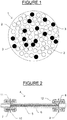
- the separation media 1 comprises a mixture of first particles 2 (represented by open circles) and second particles 3 (represented by filled circles).
- the second particles 3 have a higher thermal conductivity than the first particles 2.
- the thermal conductivity of the material comprising the second particle is ten times greater than the material comprising the first particle.
- the thermal conductivity of the material of the second particles 3 is preferably selected to be greater than 0,1 W.cm -1 .°K -1 , whereas the thermal conductivity of the material of the first particles 2 is typically about 0.01 W.cm -1 .°K -1 .
- the material of the first particle is selected for its affinity for the analyte
- the material of the second particle is selected for the thermal conductivity.
- the addition of the second particles 3 to the first particles 2 increases the thermal conductivity of the separation media 1 beyond that of the first particles 2 alone.
- Separation media has utility for chromatographic or electrophoretic separation of components of a sample mixture, or for the selective absorption of one or more components of a mixture on a substrate, typically prior to analysis of the absorbed components by another analytical technique.
- the first material from which the first particles are made is siliceous polymers, for example polyethoxysilane and others described below.
- the first particles are sized between 1 and 100 ⁇ m.
- the first particles are between 1 and 10 ⁇ m.
- the first particles are sized less than 2 ⁇ m.
- the particles can be any shape including irregular shapes.
- the particles are approximately spherical.
- the first particles are porous or non-porous, and, preferably, are porous.
- the second material, from which the second particles are made, is selected to have a higher thermal conductivity than the first material from which the first particles are made.
- the second material may have a thermal conductivity in the range 0.1 - 50 W.cm -1 .°K -1 .
- the thermal conductivity of the second material is, preferably, selected to be ten-fold greater than the thermal conductivity of the material of the first particle.
- a preferred range is 1 - 10 W.cm -1 .°K -1 , to 1 - 50 W.cm -1 .°K -1 .
- the second material is selected to have as little chromatographic effect.
- the addition of a second material type may influence peak shape unless the second material is relatively inert under the conditions used for the separation or absorption.
- the potential detrimental effect on peak shape is addressed by maintaining the concentration of the second particle as low as possible while taking advantage of the thermal conductivity.
- the second material is diamond or graphite.
- the thermal conductivity of diamond is 10-26 W.cm -1 .°K -1 .
- the thermal concuctivity of graphite is 0.25-4.7 W.cm -1 .°K -1 .
- These thermal conductivities may be compared with the values for some commonly used chromatographic separation materials that might be used for the first particles, listed in Table 2 below: TABLE 2 Approximate thermal conductivities of some chromatographic materials Particle Material Thermal Conductivity (W,cm -1 ,°K -1 ) Silica 0.01 Glass 0.004 - 0.01 Cross-linked styrenes ⁇ 0.005
- Embodiments of separation media according to the invention suitable for chromatographic separations comprise a mixture of first and second particles comprising, for example, 1% - 25% by volume of the second particles and the remainder substantially comprising the first particles.
- the second particles comprise between 5% and 20% of the separation media.
- a concentration of second particles of approximately 10% of the separation media is a reasonable compromise with respect to the advantages of reducing thermal gradients and providing an appropriate well defined peak.
- a preferred separation media has first particles of a hybrid siliceous polymer and second particles of diamond, or graphite.
- the hybrid siliceous particles may be a methylpolyethoxysilane (structure I below) or a polyethoxysilane, (structure II below).
- the open valences above are terminal hydrogen, or alkylene, alkynylene, or arylene groups or are bonded to further subgroups of the structures depicted.
- x and y are integers from 1 to infinity.
- the first particles are represented by the formulae SiO 2 /[R 2 p R 4 q SiO t ] n or
- R 6 is a substituted or unsubstituted C 1 - C 18 alkylene, alkynylene, or arylene moiety bridging two or more silicon atoms.
- R 2 and R 4 are independently C 1 - C 18 aliphatic or aromatic moieties
- R 6 is a substituted or unsubstituted C 1 - C 18 alkylene, alkynylene, or arylene moiety bridging two or more silicon atoms. The following also applies:
- siliceous particles are coated or uncoated.
- coated refers to having the surface bonded to one or more functional groups. These functional groups are selected for the chromatographic separation to be carried out. For example, their surfaces may be modified with hydrocarbon groups, including alkyl C 8 or C 18 groups, phenyl, aryl, or carbamate groups. Methods of preparing and coating these siliceous polymeric particles are disclosed in the above-referenced patent US 6,686,035 .
- Particles of structure I and sizes between 5 ⁇ m and 25 ⁇ m are available in the form of "XTerraTM” chromatographic columns from Waters Corporation, Milford, MA.
- Particles of structure II having a size of 1.7 ⁇ m are also available in the form of "ACQUITY UPLC®” or “XBridgeTM” chromatographic columns from Waters Corporation. Both types of particles are available with a variety of organofunctional coatings.
- Siliceous polymer separation media according to the invention is made by mixing the polymer particles described above with similar-sized particles selected from Table 2 above.
- the second material is selected from the group consisting of diamond and graphite.
- the media may comprise between 1 and 25% of the second particles. However, about 10% diamond has been found to give good results.
- Diamond particles suitable for use in separation media according to the invention comprise natural diamond or high-pressure synthetic diamond manufactured by chemical vapour deposition (CVD) induced by RF, microwave, electron cyclotron resonance (ECR), etc, or by ion sputtering processes. Suitable diamond particles are commercially available, for example from Element Six, Netherlands.
- FIG. 2 apparatus for the chromatographic separation of a mixture, a chromatographic column, generally designated by the numeral 4, is depicted.
- Column 4 comprises a stainless steel tubular member 6 packed with separation media 5 as described above.
- the separation media 5 is confined within the tubular member 6 by means of porous frits 7 and 8 respectively located at the inlet 11 and outlet 12 of the tubular member 6.
- Pipe connections 10 are provided at each end of the tubular member 6 to allow the column to be installed in otherwise conventional liquid chromatographic apparatus.
- HPLC analytical system 111 comprises the following major elements: a high-pressure pump 13, a sample injection device 14 and a detector or collector 15.
- the HPLC system has a chromatographic column 4 in fluid communication with the sample injection device 14, high-pressure pump 13, and detector or collector 15.
- the sample injection device 14 is used to introduce a sample from a reservoir 27 into the flow of mobile phase from the pump 13.
- Constituents of a mobile phase (which may comprise a mixture of several solvents and/or additives) are stored in a reservoir system 16.
- the pump 13 is provided to pump the mobile phase through the column 4, and may be capable of providing to the column 4 a mobile phase whose composition varies with time, for example to allow gradient elution to be carried out.
- Eluent from the column 4 is received by a detector or collector system 15.
- the HPLC system 111 may be used for either analytical purposes or preparative purposes.
- detector system 15 may comprise a detector responsive to at least one of the components comprised in a sample mixture to be analysed. Suitable detectors include UV absorption detectors, evaporative light scattering detectors, refractive index detectors, fluorescence detectors, electrochemical detectors, or mass spectrometric detectors. If the apparatus is to be used to prepare samples of constituents comprised in a sample mixture, detector system 15 may comprise a non-destructive detector such as a UV absorption detector, and a number of vessels or a sample plate comprising a number of wells, each vessel or well for receiving a particular constituent as it elutes from the column 4.
- a non-destructive detector such as a UV absorption detector
- Means may also be provided to minimize the temperature gradient along the axis of the tubular member 6, which may otherwise develop due to the flow of mobile phase through the separation media 5.
- An insulated jacket 30 comprising a heater and one or more temperature sensors may be disposed around the tubular member 6.
- a temperature controller 31 may also be provided to control the power supplied to the heater in response to a signal from the one or more temperature sensors so that the temperature of the tubular member 6 is maintained approximately constant along at least a substantial portion of its length.
- the heater may be replaced by one or more cooling devices (for example, Peltier effect devices) and the temperature controller 31 adjusted to maintain the temperature of the tubular member 6 below ambient.
- Alternative methods of minimizing the temperature gradient along the tubular member 6, comprise, by way of example, without limitation, immersion of tubular member 6 in a temperature-controlled water bath, or subjecting the tubular member 6 to a flow of heated (or cooled) air from a fan.
- HPLC systems 111 for carrying out a high-resolution analytical separations are sold by several vendors, such as the ALLIANCE ® and ACQUITY UPLC® systems available form Waters Corporation (Milford, MA).
- HPLC systems 111 for preparative uses are sold by several vendors such as the Delta 600 fluid handling unit also available from Waters Corporation.
- FIG. 4 is a schematic drawing of a capillary electrophoresis apparatus, generally designated by the numeral 112.
- a capillary column 19 (described in detail below) comprising separation media according to the invention is disposed between reservoirs 18 and 20, each containing a buffer solution.
- a high-voltage power supply 21 is connected as shown to provide a potential difference of up to 30kV (dependent on the nature of the buffer solution and the separation media) across the ends of the column 19. This potential difference provides an electromigratory force that causes the buffer solution to flow from the reservoir 20 to the reservoir 18 via a detector 22.
- a sample mixture is introduced into a third reservoir 17 that also contains buffer solution.
- the power supply 21 is switched off and the reservoir 17 (containing a sample) is substituted in place of the reservoir 20. Power supply 21 is then switched on so that the sample-bearing buffer solution is driven onto the column 19. Reservoir 17 is then replaced by reservoir 20 (containing only the buffer solution). The separation is continued so that the constituents of the sample are separated in time and pass in sequence through the detector 19.
- a fused silica capillary tube 23 has an internal surface 24 on which a coating 25 is applied.
- the coating 25 may comprise separation media as described.
- the coating 25 may comprise a mixture of first particles of a siliceous polymer and second particles of diamond.
- the coating 25 can be applied by any method conventionally employed for coating capillary columns using separation media according to the invention.
- the capillary tube 23 is between 10 and 100 cm long, a diameter of approximately 25 to 250 ⁇ m and an external diameter of 200 to 500 ⁇ m.
- a typical capillary tube 23 has a internal diameter of 75 ⁇ m and a external diameter of 375 ⁇ m.
- One embodiment of the present invention features a capillary columns similar to capillary column 19, shown in figure 5 , in place of the column 4 depicted in the apparatus 111 shown in figure 3 .
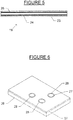
- FIG. 6 An embodiment of the invention for selectively absorbing one or more constituents of a sample mixture is illustrated in figure 6 . It comprises a plate substrate 26 to which a coating 27 is applied.
- the coating 27 comprises separation media as described above.
- Substrate 26 is any suitable material such as glass, quartz, silica, stainless steel, synthetic diamond, ceramic materials such as titanium carbide, or a plastic material.
- the substrate 26 is in the form of a plate, as depicted, or a rod, or a solid body of any convenient shape.
- Plate 26 has one or more wells 28, the interior of which has a coating 27. Each well 28 is constructed and arranged to receive a fluid sample.
- the coating 27 is the separation media according to the invention.
- the separation media is of any of the forms described, however, for this discussion the separation media will be described as being chemically modified in order to provide selective absorption of a desired chemical species.
- linker moieties are provided in a manner known in the art to attach antibodies to the surface.
- the antibodies have specific affinity to selected haptens, often proteins, so that particular proteins can be retained on the coating through an immunological interaction.
- This embodiment can be used to extract specific chemical species or even specific molecules from a complex mixture for analytical or preparative purposes.
- the higher thermal conductivity of coatings allow for distribution and dissipation of thermal energy.
- the plates 26 are used for matrix laser desorption ionization (MALDI) processes.
- the coating 27 is a gel, for example a polyacrylamide gel, allowing the apparatus to be used for gel electrophoresis.
- the first particles of the invention may comprise polyacrylamide to which second particles of gold or diamond are added to increase the thermal conductivity of the gel.
- Substrate 26 of the figure 6 apparatus may be made from the same material used for the coating 27, especially if the material comprises both the first and second particles of the invention and also a filler or a binding agent.
- Embodiments of the invention according to figure 6 may be used for MALDI or laser desorption mass spectroscopy, where the improved thermal conductivity of plates according to the invention has been found to be especially valuable. They may also be used as sample receptacles useful in combinatorial chemistry experiments, especially when configured as multiple well plates.
- solid substrates 26 according to the invention are be produced in granular or powder form with chemically modified surfaces that allow the grains to selectively adsorb specific types of chemical species. These embodiments may be used to extract species that are selectively absorbed on them from complex mixtures.
- a mobile phase comprising 65% acetonitile, 35% water was used.
- a test sample comprising 9.6 ⁇ g/ml thiourea, 0.77mg/ml toluene, 96 ⁇ g/ml naphthalene, 384 ⁇ g/ml acenaphthene, 500 ⁇ g/ml benzene, 0.1 ⁇ l/ml heptanophenone and 3 ⁇ l/ml amylbenzene, was used to obtain the results listed below.
- a sample loop of 2 ⁇ l volume was employed, and detection was by a UV absorbance detector tuned to 254nm.
- a Waters corporation "ACQUITY UPLC®" pump system was used.
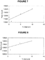
- Figures 7 and 8 are plots of the column efficiency (as represented by the number of theoretical plates) against the percentage of diamond particles for columns 1-4 under ambient and adiabatic conditions, respectively. They, and the other figures in Table 4, show a clear trend of higher column efficiencies with the increasing percentage of diamond particles in the columns, particularly for the columns operated under "ambient" conditions ( Figure 7 ).
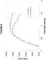
- Figure 9 is a plot showing the variation of column efficiency (as represented by the number of theoretical plates) with the flow rate of mobile phase, based on an analysis of the results for column no. 1 (comprising no diamond particles) and column no 4 (comprising 10% diamond particles), operated under "ambient" conditions. It is clear that the efficiency of column 4 is greater than that of column 1 at all but the lowest flow rates.
- Figures 7 and 8 also show that greater increases in column efficiency are obtained when columns are operated under "ambient” temperature conditions than under "adiabatic” conditions.
Description
- This invention relates to separation media for selectively absorbing certain chemical species, especially for analytical purposes. The media are useful in liquid chromatography, supercritical fluid chromatography and electrochromatography or electrophoresis, especially for the types of high pressure liquid chromatography and chromatography at extreme pressures of greater than 5,000 pounds per square inch (PSI), nanoflow LC, and microbore LC.
- Mixtures comprising components having different chemical structures are frequently separated for analytical or preparative purposes by chromatography. An aliquot of such a mixture may be introduced into a mobile phase (which may be gas, liquid or a supercritical fluid). The mobile phase is caused to flow through a stationary phase comprising separation media. Components of the mixture may interact differently with the separation media and may be retained by it for different periods. Components may therefore elute from the separation media at different times and may be collected or detected by any means responsive to a selected property of the components of interest. As used herein, the term "sample" is directed to the solutions and mixtures which are analysed to determine one or more components of interest.
- Mobile phase may be caused to flow through the separation media by virtue of its pressure (if a gas or supercritical fluid), by pumping, or by the influence of an electrical field (in electrochromatography or capillary electrophoresis). A combination of these processes may also be used.
- In a related technique, a complex mixture can be separated by depositing it on separation media (typically a gel) supported on a surface, and causing the components comprised in the mixture to migrate through the media by means of an electrical field. A variety of different techniques may then be used to mark the positions of different components in the media after the field has been applied for a given time. Certain components in a complex mixture may also be selectively absorbed on separation media in order to separate them from unwanted components, and then analysed using other techniques, for example mass spectrometry or other spectroscopic techniques.
- Chromatographic separation media may comprise small particles packed in a tubular column (usually made of stainless steel or fused silica) or may comprise a coating on the interior wall of a capillary tube. Some current columns comprise particles as small as 1 micron and operate at pressures as high as 15,000 - 100,000 psi. Although these columns generally exhibit greater separation efficiency than columns comprising larger particles, it is thought that still greater efficiency could be realised by the use of separation media more suited to the high pressures used.
- In general, the efficiency of all such separation techniques is to some extent dependent on the nature of the separation media. The present invention relates to improved separation media particularly suitable for use at very high pressure of a chromatographic mobile phase, but which also may advantageously be used in a variety of other techniques to improve the separation of components in complex mixtures.
-
WO 2006/099509 discloses adsorbent magnetic particles used to remove air pollutants. -
US 2003/150811 discloses porous inorganic/organic hybrid monolith materials for chromatographic separations. -
WO 2004/071619 discloses a chromatography column packed with a mixture of a particulate stationary phase material and a polymeric network of cross-linked poly(diorganosiloxane). -
WO 2006/130408 discloses a method for making a fluid-processing apparatus involving mixing a colloidal suspension with a matrix material, applying the mixture to a surface of a conduit, and curing the applied mixture to provide a conductive coating. - De Jong, K. P, et al. (1980), Applications of surface science, 6(3-4), pp. 273-287 discloses silica supported copper particles.
- The inventors have found that, particularly in the case of chromatographic separations carried out at very high pressure, increasing the thermal conductivity of prior types of separation media, or adding material of high thermal conductivity to the separation media, improves the separation efficiency of that media. The invention therefore provides improved separation media, as defined in
claim 1, for use in the high pressure chromatographic separation of a sample mixture. - A further embodiment of the invention is directed to an apparatus for the high pressure chromatographic separation of a sample mixture comprising a tubular member having an inlet through which a fluid may enter and an outlet through which fluid may leave. The tubular member has an interior space disposed between the inlet and the outlet, wherein there is disposed in such interior space, a separation media as defined in
claim 1. - The first particles of a first material comprise particles of siliceous polymers. These particles are coated or uncoated. As used herein, the term "coating" refers to a layer or reaction product of the particle surface with chemical agents to bond chemically functional moieties. Such moieties may comprise alkyl, aryl, phenyl or carbamate groups, or other groups used in prior types of separation media. The first particles are porous or non-porous. The first particles are sized between 1 micron and 100 microns, but most preferably are between 1 and 10 microns. The first particles are any shape including irregular shapes, but preferably are approximately spherical.
- The second particles comprise the second material that has a higher thermal conductivity than the material of which the first particles are comprised. The second material is diamond or graphite.
- Preferably, the second material has a thermal conductivity greater than 0.5 W.cm-1.°K-1, and, most preferably, greater than 1 W.cm-1.°K-1. Preferably, the thermal conductivity of the second material is approximately tenfold greater than that of the first material.
- Preferably, the first and second particles are approximately the same size. The first particles are normally sized as the particles that might be used to prepare prior types of separation media comprising only the first particles.
- Preferably, approximately 1% and 25% of separation media comprise the second particles. The remainder of the separation media is the first particles. A more preferred range is between 5% and 20% of the separation media is the second particles; and, more preferred, about 10%.
- Preferably, the first particles are responsible for the at least temporary retention of components of a sample by the separation media. The second particles are primarily added to increase the thermal conductivity of the substrate to a value greater than that of the first particles alone, However, those skilled in the art will recognise that the second particles also interact with components of the sample and for at least some of those components to be at least temporarily retained by the second particles.
- The inventors have found that by the use of separation media as described, the performance of high-pressure liquid chromatography in particular can be significantly improved. For example, the separation between two chromatographic peaks which are poorly resolved using separation media comprising only the first particles can be significantly improved using separation media comprising high thermal conductivity second particles in addition to the first particles, using otherwise similar chromatographic conditions.
- Without wishing to be bound by theory, the inventors believe that the use of separation media according to the invention may reduce the detrimental effect of frictional heating that is thought to take place at very high pressure. It is speculated that the use of separation media having a higher thermal conductivity than that of the first particles alone can reduce the thermal gradients in the mobile phase that are probably caused by this heating and in so doing increase the resolution of the separation.
- Other features and advantages of the present invention will be apparent to those skilled in the art upon reading the detailed description and viewing the Figures that follow.
- Embodiments of the invention will now be described in detail with reference to the figures, in which:
-
Figure 1 is a schematic representation of one embodiment of separation media according to the invention; -
Figure 2 is a drawing of a chromatographic column according to the invention; -
Figure 3 is a drawing of an embodiment of apparatus for the chromatographic separation of a mixture according to the invention; -
Figure 4 is a drawing of an embodiment of apparatus for the electrophoretic separation of a mixture according to the invention; -
Figure 5 is a drawing of a capillary column according to the invention; and -
Figure 6 is a drawing of an embodiment of apparatus according to the invention for selectively absorbing at least one component comprised in a sample mixture. -
Figure 7 is a plot of the efficiency of various chromatographic columns operated under ambient temperature conditions against the percentage of diamond particles they contain; -
Figure 8 is a plot of the efficiency of various chromatographic columns operated under adiabatic temperature conditions against the percentage of diamond particles they contain; and -
Figure 9 is a plot of the efficiencies of two chromatographic columns comprising different percentages of diamond particles against the flow rate of mobile phase. - Embodiments of the present invention will be described in detail as to preferred devices, articles of manufacture and methods featuring a separation media. As used herein, unless the context requires otherwise, the term "column" refers to all separation devices having a conduit in which a separation media is placed, including column cartridges and capillaries.
- Turning now to
Figure 1 , a separation media according to the invention, generally designated by thenumeral 1, is depicted. Theseparation media 1 comprises a mixture of first particles 2 (represented by open circles) and second particles 3 (represented by filled circles). Thesecond particles 3 have a higher thermal conductivity than thefirst particles 2. Preferably, the thermal conductivity of the material comprising the second particle is ten times greater than the material comprising the first particle. For example, the thermal conductivity of the material of thesecond particles 3 is preferably selected to be greater than 0,1 W.cm-1.°K-1, whereas the thermal conductivity of the material of thefirst particles 2 is typically about 0.01 W.cm-1.°K-1. The material of the first particle is selected for its affinity for the analyte, The material of the second particle is selected for the thermal conductivity. The addition of thesecond particles 3 to thefirst particles 2 increases the thermal conductivity of theseparation media 1 beyond that of thefirst particles 2 alone. - Separation media provided by the invention has utility for chromatographic or electrophoretic separation of components of a sample mixture, or for the selective absorption of one or more components of a mixture on a substrate, typically prior to analysis of the absorbed components by another analytical technique. The first material from which the first particles are made is siliceous polymers, for example polyethoxysilane and others described below.
- The first particles are sized between 1 and 100 µm. For chromatographic embodiments, for example reverse-phase liquid chromatography, the first particles are between 1 and 10 µm. For extreme pressure applications, the first particles are sized less than 2 µm. The particles can be any shape including irregular shapes. Preferably, the particles are approximately spherical. The first particles are porous or non-porous, and, preferably, are porous.
- The second material, from which the second particles are made, is selected to have a higher thermal conductivity than the first material from which the first particles are made. Typically, the second material may have a thermal conductivity in the range 0.1 - 50 W.cm-1.°K-1. The thermal conductivity of the second material is, preferably, selected to be ten-fold greater than the thermal conductivity of the material of the first particle. A preferred range is 1 - 10 W.cm-1.°K-1, to 1 - 50 W.cm-1.°K-1.
- The second material is selected to have as little chromatographic effect. The addition of a second material type may influence peak shape unless the second material is relatively inert under the conditions used for the separation or absorption. The potential detrimental effect on peak shape is addressed by maintaining the concentration of the second particle as low as possible while taking advantage of the thermal conductivity.
- The second material is diamond or graphite.
- The thermal conductivity of diamond is 10-26 W.cm-1.°K-1. The thermal concuctivity of graphite is 0.25-4.7 W.cm-1.°K-1.
These thermal conductivities may be compared with the values for some commonly used chromatographic separation materials that might be used for the first particles, listed in Table 2 below:TABLE 2 Approximate thermal conductivities of some chromatographic materials Particle Material Thermal Conductivity (W,cm-1,°K-1) Silica 0.01 Glass 0.004 - 0.01 Cross-linked styrenes < 0.005 - It can be seen from Tables 1 and 2 that the addition of second particles selected from table 1 to those listed in table 2 can markedly increase the thermal conductivity of the resulting media, especially when the second material has a very high thermal conductivity, such as diamond, gold, or certain forms of graphite.
- Embodiments of separation media according to the invention suitable for chromatographic separations comprise a mixture of first and second particles comprising, for example, 1% - 25% by volume of the second particles and the remainder substantially comprising the first particles. Preferably, the second particles comprise between 5% and 20% of the separation media. A concentration of second particles of approximately 10% of the separation media is a reasonable compromise with respect to the advantages of reducing thermal gradients and providing an appropriate well defined peak.
- A preferred separation media has first particles of a hybrid siliceous polymer and second particles of diamond, or graphite. The hybrid siliceous particles may be a methylpolyethoxysilane (structure I below) or a polyethoxysilane, (structure II below).


- The open valences above are terminal hydrogen, or alkylene, alkynylene, or arylene groups or are bonded to further subgroups of the structures depicted. As used above, x and y are integers from 1 to infinity.
- The first particles are represented by the formulae SiO2/[R2 pR4 qSiOt]n or
- SiO2/[R6(R2 rSiOt)m]n, where R2 and R4 are independently C1 - C18 aliphatic or aromatic moieties, R6 is a substituted or unsubstituted C1 - C18 alkylene, alkynylene, or arylene moiety bridging two or more silicon atoms. The following also applies:
- a. p+q = 1 or 2;
- b. if p+q = 1, t = 1.5;
- c. if p+q = 2, t = 1;
- d. r = 0 or 1;
- e. if r=0, t = 1.5;
- f. if r=1, t=1.
- g. m is an integer ≥ 2;
- h. n is a number between 0.03 and 1.
- These siliceous particles are coated or uncoated. As used herein, the term "coated" refers to having the surface bonded to one or more functional groups. These functional groups are selected for the chromatographic separation to be carried out. For example, their surfaces may be modified with hydrocarbon groups, including alkyl C8 or C18 groups, phenyl, aryl, or carbamate groups. Methods of preparing and coating these siliceous polymeric particles are disclosed in the above-referenced patent
US 6,686,035 . - Particles of structure I and sizes between 5 µm and 25 µm are available in the form of "XTerra™" chromatographic columns from Waters Corporation, Milford, MA. Particles of structure II having a size of 1.7 µm are also available in the form of "ACQUITY UPLC®" or "XBridge™" chromatographic columns from Waters Corporation. Both types of particles are available with a variety of organofunctional coatings.
- Siliceous polymer separation media according to the invention is made by mixing the polymer particles described above with similar-sized particles selected from Table 2 above. The second material is selected from the group consisting of diamond and graphite.
- The media may comprise between 1 and 25% of the second particles. However, about 10% diamond has been found to give good results.
- Diamond particles suitable for use in separation media according to the invention comprise natural diamond or high-pressure synthetic diamond manufactured by chemical vapour deposition (CVD) induced by RF, microwave, electron cyclotron resonance (ECR), etc, or by ion sputtering processes. Suitable diamond particles are commercially available, for example from Element Six, Netherlands.
- Turning now to
Figure 2 , apparatus for the chromatographic separation of a mixture, a chromatographic column, generally designated by thenumeral 4, is depicted.Column 4 comprises a stainlesssteel tubular member 6 packed withseparation media 5 as described above. Theseparation media 5 is confined within thetubular member 6 by means ofporous frits 7 and 8 respectively located at theinlet 11 andoutlet 12 of thetubular member 6.Pipe connections 10 are provided at each end of thetubular member 6 to allow the column to be installed in otherwise conventional liquid chromatographic apparatus. - Turning now to
Figure 3 , a high-pressure liquid chromatography (HPLC) system embodying features of the present invention, generally designated by the numeral 111, is depicted. HPLC analytical system 111 comprises the following major elements: a high-pressure pump 13, asample injection device 14 and a detector orcollector 15. The HPLC system has achromatographic column 4 in fluid communication with thesample injection device 14, high-pressure pump 13, and detector orcollector 15. - The
sample injection device 14 is used to introduce a sample from areservoir 27 into the flow of mobile phase from thepump 13. Constituents of a mobile phase (which may comprise a mixture of several solvents and/or additives) are stored in areservoir system 16. Thepump 13 is provided to pump the mobile phase through thecolumn 4, and may be capable of providing to the column 4 a mobile phase whose composition varies with time, for example to allow gradient elution to be carried out. Eluent from thecolumn 4 is received by a detector orcollector system 15. - The HPLC system 111 may be used for either analytical purposes or preparative purposes. If used for analytical purposes,
detector system 15 may comprise a detector responsive to at least one of the components comprised in a sample mixture to be analysed. Suitable detectors include UV absorption detectors, evaporative light scattering detectors, refractive index detectors, fluorescence detectors, electrochemical detectors, or mass spectrometric detectors. If the apparatus is to be used to prepare samples of constituents comprised in a sample mixture,detector system 15 may comprise a non-destructive detector such as a UV absorption detector, and a number of vessels or a sample plate comprising a number of wells, each vessel or well for receiving a particular constituent as it elutes from thecolumn 4. - Means may also be provided to minimize the temperature gradient along the axis of the
tubular member 6, which may otherwise develop due to the flow of mobile phase through theseparation media 5. Aninsulated jacket 30 comprising a heater and one or more temperature sensors may be disposed around thetubular member 6. Atemperature controller 31 may also be provided to control the power supplied to the heater in response to a signal from the one or more temperature sensors so that the temperature of thetubular member 6 is maintained approximately constant along at least a substantial portion of its length. In the alternative, in the event the components being separated are heat sensitive, the heater may be replaced by one or more cooling devices (for example, Peltier effect devices) and thetemperature controller 31 adjusted to maintain the temperature of thetubular member 6 below ambient. - Alternative methods of minimizing the temperature gradient along the
tubular member 6, comprise, by way of example, without limitation, immersion oftubular member 6 in a temperature-controlled water bath, or subjecting thetubular member 6 to a flow of heated (or cooled) air from a fan. - HPLC systems 111 for carrying out a high-resolution analytical separations are sold by several vendors, such as the ALLIANCE ® and ACQUITY UPLC® systems available form Waters Corporation (Milford, MA). HPLC systems 111 for preparative uses are sold by several vendors such as the Delta 600 fluid handling unit also available from Waters Corporation.
-
Figure 4 is a schematic drawing of a capillary electrophoresis apparatus, generally designated by the numeral 112. A capillary column 19 (described in detail below) comprising separation media according to the invention is disposed betweenreservoirs voltage power supply 21 is connected as shown to provide a potential difference of up to 30kV (dependent on the nature of the buffer solution and the separation media) across the ends of thecolumn 19. This potential difference provides an electromigratory force that causes the buffer solution to flow from thereservoir 20 to thereservoir 18 via adetector 22. A sample mixture is introduced into athird reservoir 17 that also contains buffer solution. In order to analyse the sample, thepower supply 21 is switched off and the reservoir 17 (containing a sample) is substituted in place of thereservoir 20.Power supply 21 is then switched on so that the sample-bearing buffer solution is driven onto thecolumn 19.Reservoir 17 is then replaced by reservoir 20 (containing only the buffer solution). The separation is continued so that the constituents of the sample are separated in time and pass in sequence through thedetector 19. - A
suitable column 19 for use in the apparatus offigure 4 is shown infigure 5 . A fusedsilica capillary tube 23 has aninternal surface 24 on which acoating 25 is applied. Thecoating 25 may comprise separation media as described. For example, thecoating 25 may comprise a mixture of first particles of a siliceous polymer and second particles of diamond. Thecoating 25 can be applied by any method conventionally employed for coating capillary columns using separation media according to the invention. Thecapillary tube 23 is between 10 and 100 cm long, a diameter of approximately 25 to 250 µm and an external diameter of 200 to 500 µm. Atypical capillary tube 23 has a internal diameter of 75 µm and a external diameter of 375 µm. - One embodiment of the present invention features a capillary columns similar to
capillary column 19, shown infigure 5 , in place of thecolumn 4 depicted in the apparatus 111 shown infigure 3 . - An embodiment of the invention for selectively absorbing one or more constituents of a sample mixture is illustrated in
figure 6 . It comprises aplate substrate 26 to which acoating 27 is applied. Thecoating 27 comprises separation media as described above.Substrate 26 is any suitable material such as glass, quartz, silica, stainless steel, synthetic diamond, ceramic materials such as titanium carbide, or a plastic material. Thesubstrate 26 is in the form of a plate, as depicted, or a rod, or a solid body of any convenient shape.Plate 26 has one ormore wells 28, the interior of which has acoating 27. Each well 28 is constructed and arranged to receive a fluid sample. Thecoating 27 is the separation media according to the invention. - The separation media is of any of the forms described, however, for this discussion the separation media will be described as being chemically modified in order to provide selective absorption of a desired chemical species. For example, linker moieties are provided in a manner known in the art to attach antibodies to the surface. The antibodies have specific affinity to selected haptens, often proteins, so that particular proteins can be retained on the coating through an immunological interaction. This embodiment can be used to extract specific chemical species or even specific molecules from a complex mixture for analytical or preparative purposes. The higher thermal conductivity of coatings allow for distribution and dissipation of thermal energy. The
plates 26 are used for matrix laser desorption ionization (MALDI) processes. - Disclosed but not claimed is wherein the
coating 27 is a gel, for example a polyacrylamide gel, allowing the apparatus to be used for gel electrophoresis. In such an embodiment, the first particles of the invention may comprise polyacrylamide to which second particles of gold or diamond are added to increase the thermal conductivity of the gel. -
Substrate 26 of thefigure 6 apparatus may be made from the same material used for thecoating 27, especially if the material comprises both the first and second particles of the invention and also a filler or a binding agent. - Embodiments of the invention according to
figure 6 may be used for MALDI or laser desorption mass spectroscopy, where the improved thermal conductivity of plates according to the invention has been found to be especially valuable. They may also be used as sample receptacles useful in combinatorial chemistry experiments, especially when configured as multiple well plates. - In the alternative,
solid substrates 26 according to the invention are be produced in granular or powder form with chemically modified surfaces that allow the grains to selectively adsorb specific types of chemical species. These embodiments may be used to extract species that are selectively absorbed on them from complex mixtures. - Four 50 mm long chromatographic columns, listed in Table 3 below, were packed using a downward slurry packing method with mixtures of "ACQUITY UPLC®" 1.7µm BEH particles (structure II above, and available from Waters corporation, Milford, MA) and various proportions of non-porous, irregularly shaped 1.5 - 2.5 µm diamond particles.
TABLE 3 Col. No Internal diameter (mm) % of diamond particles 1 3.0 0 2 3.0 1 3 3.0 5 4 3.0 10 - For the following experiments, a mobile phase comprising 65% acetonitile, 35% water was used. A test sample comprising 9.6µg/ml thiourea, 0.77mg/ml toluene, 96µg/ml naphthalene, 384µg/ml acenaphthene, 500µg/ml benzene, 0.1µl/ml heptanophenone and 3µl/ml amylbenzene, was used to obtain the results listed below. A sample loop of 2µl volume was employed, and detection was by a UV absorbance detector tuned to 254nm. A Waters corporation "ACQUITY UPLC®" pump system was used.
- Data relevant to the performance of the four columns is listed in Table 4. The figures in table 4 relate to the heptanophenone component in the test sample. Data relating to "ambient" operation was obtained with the external surface of the columns in contact with ambient air, whereas the "adiabatic" data was obtained with the columns insulated from ambient air by layers of glass fibre tape. The retention factors listed have been corrected for extra-column contributions.
TABLE 4 Col. No. Retention Factor (Ambient) Theoretical Plates (Ambient) Retention Factor (Adiabatic) Theoretical Plates (Adiabatic) 1 6.19 11493 6.16 12813 2 6.18 10259 6.05 11325 3 5.98 12487 6.04 13360 4 5.93 14103 5.087 14051 -
Figures 7 and 8 are plots of the column efficiency (as represented by the number of theoretical plates) against the percentage of diamond particles for columns 1-4 under ambient and adiabatic conditions, respectively. They, and the other figures in Table 4, show a clear trend of higher column efficiencies with the increasing percentage of diamond particles in the columns, particularly for the columns operated under "ambient" conditions (Figure 7 ). -
Figure 9 is a plot showing the variation of column efficiency (as represented by the number of theoretical plates) with the flow rate of mobile phase, based on an analysis of the results for column no. 1 (comprising no diamond particles) and column no 4 (comprising 10% diamond particles), operated under "ambient" conditions. It is clear that the efficiency ofcolumn 4 is greater than that ofcolumn 1 at all but the lowest flow rates. -
Figures 7 and 8 also show that greater increases in column efficiency are obtained when columns are operated under "ambient" temperature conditions than under "adiabatic" conditions.
Claims (8)
- Separation media for use in the high pressure chromatographic separation of a sample mixture, said separation media comprising first particles of a first material and second particles of a second material, said first particles being sized between 1 and 100 µm, said first particles being capable of at least temporarily retaining at least one component of a sample mixture, and said second material being selected to have a higher thermal conductivity than said first material, wherein said first material comprises a siliceous polymer represented by (i) the formula SiO2/[R2 pR4 qSiOt]n, where R2 and R4 are independently C1 - C18 aliphatic or aromatic moieties, p+q = 1 or 2, provided that t = 1.5 if p+q = 1 and t = 1 if p+q = 2, and n is a number between 0.03 and 1, or (ii) the formula SiO2/[R6(R2 rSiOt)m]n, where R2 is C1 - C18 aliphatic or aromatic moiety, R6 is a substituted or unsubstituted C1 - C18 alkylene, alkynylene, or arylene moiety bridging two or more silicon atoms, r = 0 or 1, provided that t = 1.5 if r = 0 and t = 1 if r = 1, m is an integer ≥ 2, and n is a number between 0.03 and 1; and said second material is selected from the group consisting of diamond and graphite.
- Separation media as claimed in claim 1, wherein said first material comprises a siliceous polymer having a structure represented by:

- Separation media as claimed in claim 1, wherein said first material comprises a siliceous polymer having a structure represented by:

- Separation media as claimed in claim 1, wherein said first particles comprise surfaces modified with functional moieties selected from the group comprising alkyl moieties, phenyl moieties, aryl moieties, or carbamate moieties.
- Apparatus for the high pressure chromatographic separation of a sample mixture comprising a tubular member having an inlet which is configured to allow that a fluid may enter and an outlet which is configured to allow that fluid may leave, said tubular member having an interior space disposed between said inlet and said outlet, wherein there is disposed in said interior space separation media as claimed in any one of claims 1 to 4.
- Apparatus as claimed in claim 5, further comprising means for minimizing any temperature gradient in an axial direction along said tubular member.
- Apparatus as claimed in claim 6, wherein said means for minimizing any temperature gradient comprises an insulated jacket surrounding said tubular member and fitted with at least one heater and at least one temperature sensor, and a temperature controller responsive to signals from said at least one temperature sensor, said temperature controller for supplying and controlling power to said at least one heater.
- Apparatus as claimed in claim 6, wherein said means for minimizing any temperature gradient comprises an insulated jacket surrounding said tubular member and fitted with at least one cooling device and at least one temperature sensor, and a temperature controller responsive to signals from said at least one temperature sensor, said temperature controller for supplying and controlling power to said at least one cooling device.
Applications Claiming Priority (2)
| Application Number | Priority Date | Filing Date | Title |
|---|---|---|---|
| US91661107P | 2007-05-08 | 2007-05-08 | |
| PCT/US2008/062737 WO2008140996A1 (en) | 2007-05-08 | 2008-05-06 | Chromatographic and electrophoretic separation media and apparatus |
Publications (3)
| Publication Number | Publication Date |
|---|---|
| EP2152403A1 EP2152403A1 (en) | 2010-02-17 |
| EP2152403A4 EP2152403A4 (en) | 2016-07-27 |
| EP2152403B1 true EP2152403B1 (en) | 2020-12-23 |
Family
ID=40002581
Family Applications (1)
| Application Number | Title | Priority Date | Filing Date |
|---|---|---|---|
| EP08747685.9A Active EP2152403B1 (en) | 2007-05-08 | 2008-05-06 | Separation media and apparatus |
Country Status (4)
| Country | Link |
|---|---|
| US (1) | US20100278695A1 (en) |
| EP (1) | EP2152403B1 (en) |
| JP (1) | JP2010527003A (en) |
| WO (1) | WO2008140996A1 (en) |
Families Citing this family (6)
| Publication number | Priority date | Publication date | Assignee | Title |
|---|---|---|---|---|
| JP2011112375A (en) * | 2009-11-24 | 2011-06-09 | Hitachi High-Technologies Corp | Thermostatic device and capillary electrophoretic apparatus |
| JP5992036B2 (en) * | 2011-06-03 | 2016-09-14 | ダウ グローバル テクノロジーズ エルエルシー | Polymer chromatography |
| DE102013020400A1 (en) * | 2013-12-10 | 2015-06-11 | Merck Patent Gmbh | cleaning device |
| JP6063095B2 (en) * | 2014-06-25 | 2017-01-18 | タツタ電線株式会社 | Sulfur removing material, purification column using the same, and pretreatment method for organic substance analysis |
| US9422596B1 (en) * | 2015-04-27 | 2016-08-23 | Norgen Biotek Corp. | Methods and columns for nucleic acid purification |
| CN113507972B (en) * | 2019-02-27 | 2023-10-20 | 沃特世科技公司 | Coated flow path component for chromatographic effects |
Citations (1)
| Publication number | Priority date | Publication date | Assignee | Title |
|---|---|---|---|---|
| WO2006130408A2 (en) * | 2005-06-02 | 2006-12-07 | Waters Investments Limited | Conductive conduits for chemical analyses, and methods for making such conduits |
Family Cites Families (18)
| Publication number | Priority date | Publication date | Assignee | Title |
|---|---|---|---|---|
| US3146616A (en) * | 1958-11-24 | 1964-09-01 | Phillips Petroleum Co | Thermal chromatography temperature gradient |
| US3486299A (en) * | 1967-07-06 | 1969-12-30 | Procter & Gamble | Apparatus and method for continuous vapor phase fractionation |
| US7225079B2 (en) * | 1998-08-04 | 2007-05-29 | Transgenomic, Inc. | System and method for automated matched ion polynucleotide chromatography |
| US6355165B1 (en) * | 1998-09-10 | 2002-03-12 | Transgenomic, Inc. | MIPC chromatographic apparatus with improved temperature control |
| US6686035B2 (en) | 1999-02-05 | 2004-02-03 | Waters Investments Limited | Porous inorganic/organic hybrid particles for chromatographic separations and process for their preparation |
| US6855173B2 (en) * | 2000-06-05 | 2005-02-15 | Procter & Gamble Company | Use of absorbent materials to separate water from lipophilic fluid |
| WO2003014450A1 (en) * | 2001-08-09 | 2003-02-20 | Waters Investments Limited | Porous inorganic/organic hybrid monolith materials for chromatographic separations and process for their preparation |
| US20040028901A1 (en) * | 2002-02-25 | 2004-02-12 | Rumpf Frederick H. | Compositions comprising continuous networks and monoliths |
| US6846410B2 (en) * | 2002-05-03 | 2005-01-25 | Zirchrom Separations, Inc. | High stability porous metal oxide spherules used for one-step antibody purifications |
| US20040118762A1 (en) * | 2002-12-18 | 2004-06-24 | Jishou Xu | Packing materials for liquid chromatography using chemically modified diamond powders |
| JP4791352B2 (en) * | 2003-02-07 | 2011-10-12 | ウオーターズ・テクノロジーズ・コーポレイシヨン | Polymer solid support for chromatography nanocolumns |
| DE112004000244T5 (en) | 2003-02-10 | 2006-02-09 | Waters Investments Ltd., New Castle | Siloxane-immobilized particulate stationary phases for chromatographic separations and extractions |
| US7462494B2 (en) * | 2003-06-09 | 2008-12-09 | 3M Innovative Properties Company | Method for laser desorption mass spectrometry using porous polymeric substrates with particle fillers |
| US7326837B2 (en) * | 2005-01-07 | 2008-02-05 | Academia Sinica | Clinical applications of crystalline diamond particles |
| WO2006099509A1 (en) | 2005-03-11 | 2006-09-21 | Regents Of The University Of Minnesota | Air pollutant removal using magnetic sorbent particles |
| US7708815B2 (en) * | 2005-04-22 | 2010-05-04 | Angstrom Power Incorporated | Composite hydrogen storage material and methods related thereto |
| US20070256976A1 (en) * | 2006-04-10 | 2007-11-08 | Boyes Barry E | Metal-coated sorbents as a separation medium for HPLC of phosphorus-containing materials |
| US7740690B2 (en) * | 2007-03-29 | 2010-06-22 | Praxair Technology, Inc. | Methods and systems for purifying gases |
-
2008
- 2008-05-06 WO PCT/US2008/062737 patent/WO2008140996A1/en active Application Filing
- 2008-05-06 EP EP08747685.9A patent/EP2152403B1/en active Active
- 2008-05-06 JP JP2010507593A patent/JP2010527003A/en not_active Withdrawn
- 2008-05-06 US US12/598,678 patent/US20100278695A1/en not_active Abandoned
Patent Citations (1)
| Publication number | Priority date | Publication date | Assignee | Title |
|---|---|---|---|---|
| WO2006130408A2 (en) * | 2005-06-02 | 2006-12-07 | Waters Investments Limited | Conductive conduits for chemical analyses, and methods for making such conduits |
Also Published As
| Publication number | Publication date |
|---|---|
| WO2008140996A1 (en) | 2008-11-20 |
| EP2152403A1 (en) | 2010-02-17 |
| US20100278695A1 (en) | 2010-11-04 |
| EP2152403A4 (en) | 2016-07-27 |
| JP2010527003A (en) | 2010-08-05 |
Similar Documents
| Publication | Publication Date | Title |
|---|---|---|
| Kobayashi et al. | Properties of monolithic silica columns for HPLC | |
| EP2152403B1 (en) | Separation media and apparatus | |
| Hayes et al. | Sol− Gel Open Tubular ODS Columns with Reversed Electroosmotic Flow for Capillary Electrochromatography | |
| EP1485179B1 (en) | Device for solid phase extraction and separation method | |
| US8935941B2 (en) | Method of cladding monolithic silica body and separation medium | |
| US20060013982A1 (en) | Titania-Based Coating for Capillary Microextraction | |
| Vanhoenacker et al. | Recent applications of capillary electrochromatography | |
| Yang et al. | Magnetic microsphere confined ionic liquid as a novel sorbent for the determination of chlorophenols in environmental water samples by liquid chromatography | |
| Hirata et al. | Supercritical fluid chromatography with fused-silica packed columns | |
| US6998040B2 (en) | Sol-gel open tubular ODS columns with charged inner surface for capillary electrochromatography | |
| Xie et al. | Preparation of monolithic silica column with strong cation‐exchange stationary phase for capillary electrochromatography | |
| US20190376933A1 (en) | Size exclusion chromatography of biological molecules | |
| Qu et al. | Open-tubular gas chromatography using capillary coated with octadecylamine-capped gold nanoparticles | |
| US7112277B2 (en) | Methods and systems for separating constituents of a highly aqueous fluid | |
| Cox | Practical aspects of bonded phase chromatography | |
| McCalley | Separation mechanisms in hydrophilic interaction chromatography | |
| Perchepied et al. | Insights in column packing processes of narrow bore and capillary-scale columns: Methodologies, driving forces, and separation performance–A tutorial review | |
| Leinweber et al. | Silica‐based monoliths for rapid peptide screening by capillary liquid chromatography hyphenated with electrospray ionization Fourier transform ion cyclotron resonance mass spectrometry | |
| Bell et al. | What is on your HPLC particle? A look at stationary phase chemistry synthesis | |
| Wu et al. | Fast and efficient separations using reversed phase liquid chromatography | |
| Zhao et al. | Electrochromatographic performance of graphene and graphene oxide modified silica particles packed capillary columns | |
| Svec | Capillary electrochromatography: a rapidly emerging separation method | |
| Kirkland et al. | Rapid, high-resolution high-performance liquid chromatographic analysis of antibiotics | |
| Maldaner et al. | A new thermally immobilized fluorinated stationary phase for RP‐HPLC | |
| Poole et al. | Recent advances in chromatography |
Legal Events
| Date | Code | Title | Description |
|---|---|---|---|
| PUAI | Public reference made under article 153(3) epc to a published international application that has entered the european phase |
Free format text: ORIGINAL CODE: 0009012 |
|
| 17P | Request for examination filed |
Effective date: 20091106 |
|
| AK | Designated contracting states |
Kind code of ref document: A1 Designated state(s): AT BE BG CH CY CZ DE DK EE ES FI FR GB GR HR HU IE IS IT LI LT LU LV MC MT NL NO PL PT RO SE SI SK TR |
|
| AX | Request for extension of the european patent |
Extension state: AL BA MK RS |
|
| DAX | Request for extension of the european patent (deleted) | ||
| RA4 | Supplementary search report drawn up and despatched (corrected) |
Effective date: 20160623 |
|
| RIC1 | Information provided on ipc code assigned before grant |
Ipc: B01J 20/22 20060101AFI20160617BHEP |
|
| RAP1 | Party data changed (applicant data changed or rights of an application transferred) |
Owner name: WATERS TECHNOLOGIES CORPORATION |
|
| STAA | Information on the status of an ep patent application or granted ep patent |
Free format text: STATUS: EXAMINATION IS IN PROGRESS |
|
| 17Q | First examination report despatched |
Effective date: 20180103 |
|
| GRAP | Despatch of communication of intention to grant a patent |
Free format text: ORIGINAL CODE: EPIDOSNIGR1 |
|
| STAA | Information on the status of an ep patent application or granted ep patent |
Free format text: STATUS: GRANT OF PATENT IS INTENDED |
|
| INTG | Intention to grant announced |
Effective date: 20200713 |
|
| GRAS | Grant fee paid |
Free format text: ORIGINAL CODE: EPIDOSNIGR3 |
|
| GRAA | (expected) grant |
Free format text: ORIGINAL CODE: 0009210 |
|
| STAA | Information on the status of an ep patent application or granted ep patent |
Free format text: STATUS: THE PATENT HAS BEEN GRANTED |
|
| AK | Designated contracting states |
Kind code of ref document: B1 Designated state(s): AT BE BG CH CY CZ DE DK EE ES FI FR GB GR HR HU IE IS IT LI LT LU LV MC MT NL NO PL PT RO SE SI SK TR |
|
| REG | Reference to a national code |
Ref country code: GB Ref legal event code: FG4D |
|
| REG | Reference to a national code |
Ref country code: DE Ref legal event code: R096 Ref document number: 602008063596 Country of ref document: DE |
|
| REG | Reference to a national code |
Ref country code: AT Ref legal event code: REF Ref document number: 1347205 Country of ref document: AT Kind code of ref document: T Effective date: 20210115 |
|
| REG | Reference to a national code |
Ref country code: IE Ref legal event code: FG4D |
|
| PG25 | Lapsed in a contracting state [announced via postgrant information from national office to epo] |
Ref country code: NO Free format text: LAPSE BECAUSE OF FAILURE TO SUBMIT A TRANSLATION OF THE DESCRIPTION OR TO PAY THE FEE WITHIN THE PRESCRIBED TIME-LIMIT Effective date: 20210323 Ref country code: FI Free format text: LAPSE BECAUSE OF FAILURE TO SUBMIT A TRANSLATION OF THE DESCRIPTION OR TO PAY THE FEE WITHIN THE PRESCRIBED TIME-LIMIT Effective date: 20201223 Ref country code: GR Free format text: LAPSE BECAUSE OF FAILURE TO SUBMIT A TRANSLATION OF THE DESCRIPTION OR TO PAY THE FEE WITHIN THE PRESCRIBED TIME-LIMIT Effective date: 20210324 |
|
| REG | Reference to a national code |
Ref country code: AT Ref legal event code: MK05 Ref document number: 1347205 Country of ref document: AT Kind code of ref document: T Effective date: 20201223 |
|
| REG | Reference to a national code |
Ref country code: NL Ref legal event code: MP Effective date: 20201223 |
|
| PG25 | Lapsed in a contracting state [announced via postgrant information from national office to epo] |
Ref country code: BG Free format text: LAPSE BECAUSE OF FAILURE TO SUBMIT A TRANSLATION OF THE DESCRIPTION OR TO PAY THE FEE WITHIN THE PRESCRIBED TIME-LIMIT Effective date: 20210323 Ref country code: SE Free format text: LAPSE BECAUSE OF FAILURE TO SUBMIT A TRANSLATION OF THE DESCRIPTION OR TO PAY THE FEE WITHIN THE PRESCRIBED TIME-LIMIT Effective date: 20201223 Ref country code: LV Free format text: LAPSE BECAUSE OF FAILURE TO SUBMIT A TRANSLATION OF THE DESCRIPTION OR TO PAY THE FEE WITHIN THE PRESCRIBED TIME-LIMIT Effective date: 20201223 |
|
| PG25 | Lapsed in a contracting state [announced via postgrant information from national office to epo] |
Ref country code: HR Free format text: LAPSE BECAUSE OF FAILURE TO SUBMIT A TRANSLATION OF THE DESCRIPTION OR TO PAY THE FEE WITHIN THE PRESCRIBED TIME-LIMIT Effective date: 20201223 Ref country code: NL Free format text: LAPSE BECAUSE OF FAILURE TO SUBMIT A TRANSLATION OF THE DESCRIPTION OR TO PAY THE FEE WITHIN THE PRESCRIBED TIME-LIMIT Effective date: 20201223 |
|
| REG | Reference to a national code |
Ref country code: LT Ref legal event code: MG9D |
|
| PG25 | Lapsed in a contracting state [announced via postgrant information from national office to epo] |
Ref country code: EE Free format text: LAPSE BECAUSE OF FAILURE TO SUBMIT A TRANSLATION OF THE DESCRIPTION OR TO PAY THE FEE WITHIN THE PRESCRIBED TIME-LIMIT Effective date: 20201223 Ref country code: CZ Free format text: LAPSE BECAUSE OF FAILURE TO SUBMIT A TRANSLATION OF THE DESCRIPTION OR TO PAY THE FEE WITHIN THE PRESCRIBED TIME-LIMIT Effective date: 20201223 Ref country code: SK Free format text: LAPSE BECAUSE OF FAILURE TO SUBMIT A TRANSLATION OF THE DESCRIPTION OR TO PAY THE FEE WITHIN THE PRESCRIBED TIME-LIMIT Effective date: 20201223 Ref country code: RO Free format text: LAPSE BECAUSE OF FAILURE TO SUBMIT A TRANSLATION OF THE DESCRIPTION OR TO PAY THE FEE WITHIN THE PRESCRIBED TIME-LIMIT Effective date: 20201223 Ref country code: PT Free format text: LAPSE BECAUSE OF FAILURE TO SUBMIT A TRANSLATION OF THE DESCRIPTION OR TO PAY THE FEE WITHIN THE PRESCRIBED TIME-LIMIT Effective date: 20210423 Ref country code: LT Free format text: LAPSE BECAUSE OF FAILURE TO SUBMIT A TRANSLATION OF THE DESCRIPTION OR TO PAY THE FEE WITHIN THE PRESCRIBED TIME-LIMIT Effective date: 20201223 |
|
| PG25 | Lapsed in a contracting state [announced via postgrant information from national office to epo] |
Ref country code: AT Free format text: LAPSE BECAUSE OF FAILURE TO SUBMIT A TRANSLATION OF THE DESCRIPTION OR TO PAY THE FEE WITHIN THE PRESCRIBED TIME-LIMIT Effective date: 20201223 Ref country code: PL Free format text: LAPSE BECAUSE OF FAILURE TO SUBMIT A TRANSLATION OF THE DESCRIPTION OR TO PAY THE FEE WITHIN THE PRESCRIBED TIME-LIMIT Effective date: 20201223 |
|
| REG | Reference to a national code |
Ref country code: DE Ref legal event code: R097 Ref document number: 602008063596 Country of ref document: DE |
|
| PG25 | Lapsed in a contracting state [announced via postgrant information from national office to epo] |
Ref country code: IS Free format text: LAPSE BECAUSE OF FAILURE TO SUBMIT A TRANSLATION OF THE DESCRIPTION OR TO PAY THE FEE WITHIN THE PRESCRIBED TIME-LIMIT Effective date: 20210423 |
|
| PG25 | Lapsed in a contracting state [announced via postgrant information from national office to epo] |
Ref country code: IT Free format text: LAPSE BECAUSE OF FAILURE TO SUBMIT A TRANSLATION OF THE DESCRIPTION OR TO PAY THE FEE WITHIN THE PRESCRIBED TIME-LIMIT Effective date: 20201223 |
|
| PLBE | No opposition filed within time limit |
Free format text: ORIGINAL CODE: 0009261 |
|
| STAA | Information on the status of an ep patent application or granted ep patent |
Free format text: STATUS: NO OPPOSITION FILED WITHIN TIME LIMIT |
|
| PG25 | Lapsed in a contracting state [announced via postgrant information from national office to epo] |
Ref country code: DK Free format text: LAPSE BECAUSE OF FAILURE TO SUBMIT A TRANSLATION OF THE DESCRIPTION OR TO PAY THE FEE WITHIN THE PRESCRIBED TIME-LIMIT Effective date: 20201223 Ref country code: ES Free format text: LAPSE BECAUSE OF FAILURE TO SUBMIT A TRANSLATION OF THE DESCRIPTION OR TO PAY THE FEE WITHIN THE PRESCRIBED TIME-LIMIT Effective date: 20201223 |
|
| 26N | No opposition filed |
Effective date: 20210924 |
|
| REG | Reference to a national code |
Ref country code: CH Ref legal event code: PL |
|
| PG25 | Lapsed in a contracting state [announced via postgrant information from national office to epo] |
Ref country code: CH Free format text: LAPSE BECAUSE OF NON-PAYMENT OF DUE FEES Effective date: 20210531 Ref country code: LI Free format text: LAPSE BECAUSE OF NON-PAYMENT OF DUE FEES Effective date: 20210531 Ref country code: LU Free format text: LAPSE BECAUSE OF NON-PAYMENT OF DUE FEES Effective date: 20210506 Ref country code: MC Free format text: LAPSE BECAUSE OF FAILURE TO SUBMIT A TRANSLATION OF THE DESCRIPTION OR TO PAY THE FEE WITHIN THE PRESCRIBED TIME-LIMIT Effective date: 20201223 |
|
| REG | Reference to a national code |
Ref country code: BE Ref legal event code: MM Effective date: 20210531 |
|
| PG25 | Lapsed in a contracting state [announced via postgrant information from national office to epo] |
Ref country code: SI Free format text: LAPSE BECAUSE OF FAILURE TO SUBMIT A TRANSLATION OF THE DESCRIPTION OR TO PAY THE FEE WITHIN THE PRESCRIBED TIME-LIMIT Effective date: 20201223 |
|
| PG25 | Lapsed in a contracting state [announced via postgrant information from national office to epo] |
Ref country code: IE Free format text: LAPSE BECAUSE OF NON-PAYMENT OF DUE FEES Effective date: 20210506 |
|
| PG25 | Lapsed in a contracting state [announced via postgrant information from national office to epo] |
Ref country code: IS Free format text: LAPSE BECAUSE OF FAILURE TO SUBMIT A TRANSLATION OF THE DESCRIPTION OR TO PAY THE FEE WITHIN THE PRESCRIBED TIME-LIMIT Effective date: 20210423 Ref country code: FR Free format text: LAPSE BECAUSE OF NON-PAYMENT OF DUE FEES Effective date: 20210531 |
|
| PG25 | Lapsed in a contracting state [announced via postgrant information from national office to epo] |
Ref country code: BE Free format text: LAPSE BECAUSE OF NON-PAYMENT OF DUE FEES Effective date: 20210531 |
|
| PGFP | Annual fee paid to national office [announced via postgrant information from national office to epo] |
Ref country code: GB Payment date: 20220426 Year of fee payment: 15 Ref country code: DE Payment date: 20220420 Year of fee payment: 15 |
|
| REG | Reference to a national code |
Ref country code: DE Ref legal event code: R082 Ref document number: 602008063596 Country of ref document: DE Representative=s name: FORRESTERS IP LLP, DE Ref country code: DE Ref legal event code: R082 Ref document number: 602008063596 Country of ref document: DE Representative=s name: KUEHR, VERA, DIPL.-BIOL., DE |
|
| PG25 | Lapsed in a contracting state [announced via postgrant information from national office to epo] |
Ref country code: HU Free format text: LAPSE BECAUSE OF FAILURE TO SUBMIT A TRANSLATION OF THE DESCRIPTION OR TO PAY THE FEE WITHIN THE PRESCRIBED TIME-LIMIT; INVALID AB INITIO Effective date: 20080506 Ref country code: CY Free format text: LAPSE BECAUSE OF FAILURE TO SUBMIT A TRANSLATION OF THE DESCRIPTION OR TO PAY THE FEE WITHIN THE PRESCRIBED TIME-LIMIT Effective date: 20201223 |
|
| P01 | Opt-out of the competence of the unified patent court (upc) registered |
Effective date: 20230612 |
|
| REG | Reference to a national code |
Ref country code: DE Ref legal event code: R082 Ref document number: 602008063596 Country of ref document: DE Representative=s name: FORRESTERS IP LLP, DE |
|
| REG | Reference to a national code |
Ref country code: DE Ref legal event code: R119 Ref document number: 602008063596 Country of ref document: DE |
|
| GBPC | Gb: european patent ceased through non-payment of renewal fee |
Effective date: 20230506 |