EP2151810A2 - Dispositif de visualisation à écran matriciel securisé - Google Patents
Dispositif de visualisation à écran matriciel securisé Download PDFInfo
- Publication number
- EP2151810A2 EP2151810A2 EP09165124A EP09165124A EP2151810A2 EP 2151810 A2 EP2151810 A2 EP 2151810A2 EP 09165124 A EP09165124 A EP 09165124A EP 09165124 A EP09165124 A EP 09165124A EP 2151810 A2 EP2151810 A2 EP 2151810A2
- Authority
- EP
- European Patent Office
- Prior art keywords
- screen
- electronic
- drivers
- card
- value
- Prior art date
- Legal status (The legal status is an assumption and is not a legal conclusion. Google has not performed a legal analysis and makes no representation as to the accuracy of the status listed.)
- Withdrawn
Links
Images

Classifications
-
- G—PHYSICS
- G09—EDUCATION; CRYPTOGRAPHY; DISPLAY; ADVERTISING; SEALS
- G09G—ARRANGEMENTS OR CIRCUITS FOR CONTROL OF INDICATING DEVICES USING STATIC MEANS TO PRESENT VARIABLE INFORMATION
- G09G3/00—Control arrangements or circuits, of interest only in connection with visual indicators other than cathode-ray tubes
- G09G3/20—Control arrangements or circuits, of interest only in connection with visual indicators other than cathode-ray tubes for presentation of an assembly of a number of characters, e.g. a page, by composing the assembly by combination of individual elements arranged in a matrix no fixed position being assigned to or needed to be assigned to the individual characters or partial characters
- G09G3/34—Control arrangements or circuits, of interest only in connection with visual indicators other than cathode-ray tubes for presentation of an assembly of a number of characters, e.g. a page, by composing the assembly by combination of individual elements arranged in a matrix no fixed position being assigned to or needed to be assigned to the individual characters or partial characters by control of light from an independent source
- G09G3/36—Control arrangements or circuits, of interest only in connection with visual indicators other than cathode-ray tubes for presentation of an assembly of a number of characters, e.g. a page, by composing the assembly by combination of individual elements arranged in a matrix no fixed position being assigned to or needed to be assigned to the individual characters or partial characters by control of light from an independent source using liquid crystals
- G09G3/3611—Control of matrices with row and column drivers
- G09G3/3648—Control of matrices with row and column drivers using an active matrix
- G09G3/3655—Details of drivers for counter electrodes, e.g. common electrodes for pixel capacitors or supplementary storage capacitors
-
- G—PHYSICS
- G09—EDUCATION; CRYPTOGRAPHY; DISPLAY; ADVERTISING; SEALS
- G09G—ARRANGEMENTS OR CIRCUITS FOR CONTROL OF INDICATING DEVICES USING STATIC MEANS TO PRESENT VARIABLE INFORMATION
- G09G3/00—Control arrangements or circuits, of interest only in connection with visual indicators other than cathode-ray tubes
- G09G3/006—Electronic inspection or testing of displays and display drivers, e.g. of LED or LCD displays
-
- G—PHYSICS
- G09—EDUCATION; CRYPTOGRAPHY; DISPLAY; ADVERTISING; SEALS
- G09G—ARRANGEMENTS OR CIRCUITS FOR CONTROL OF INDICATING DEVICES USING STATIC MEANS TO PRESENT VARIABLE INFORMATION
- G09G2310/00—Command of the display device
- G09G2310/02—Addressing, scanning or driving the display screen or processing steps related thereto
- G09G2310/0243—Details of the generation of driving signals
- G09G2310/0245—Clearing or presetting the whole screen independently of waveforms, e.g. on power-on
-
- G—PHYSICS
- G09—EDUCATION; CRYPTOGRAPHY; DISPLAY; ADVERTISING; SEALS
- G09G—ARRANGEMENTS OR CIRCUITS FOR CONTROL OF INDICATING DEVICES USING STATIC MEANS TO PRESENT VARIABLE INFORMATION
- G09G3/00—Control arrangements or circuits, of interest only in connection with visual indicators other than cathode-ray tubes
- G09G3/20—Control arrangements or circuits, of interest only in connection with visual indicators other than cathode-ray tubes for presentation of an assembly of a number of characters, e.g. a page, by composing the assembly by combination of individual elements arranged in a matrix no fixed position being assigned to or needed to be assigned to the individual characters or partial characters
Definitions
- the field of the invention is that of visualization devices used in a critical environment. For a number of applications and in particular in the field of aircraft dashboards, it is imperative that the display devices constantly present reliable information. Thus, in cockpit visualizations, any display of erroneous images not detectable is prohibited. Cockpit visualizations are most often matrix flat screens.
- the most commonly used technologies use liquid crystals or organic light-emitting diodes.
- the screens implementing these technologies are called LCD, acronym for "Liquid Crystal Display” or OLED, acronym for "Organic Light Emission Diode”.
- An LCD or OLED screen can be considered as an image memory refreshed periodically by electronic circuits and read by photons.
- the video image is controlled by two series of circuits called “drivers” controlling the rows and columns of the display matrix.
- the image is presented on the display screen by the “drivers” of the columns and written by the “drivers” of the lines.
- a failure of the column “drivers” causes the same content to be written on all lines.
- the image is made up of vertical lines. In this case, the failure of the display is easily detectable and there are no security problems.
- the "drivers" lines are out of order, the control electronics can no longer write images and the last image presented is preserved until the pixels are discharged by leakage currents. Given the quality of the current electronics, this discharge can take more than a minute.
- an electronic chain as represented in figure 1 and comprising a specific detection circuit CDS disposed between the electronic card CDL carrying the DL line drivers and the electronic card CP carrying the processor of the display device.
- the CDL card “line drivers” sends a write signal SE lines to the detection circuit CDS.
- This SE signal can take many forms. It can be, among other things, a signal representative of the supply current or the state of the analog outputs.
- the detection circuit processes this received signal and produces a DS output signal in the form of electronic discrete whose state is representative of the validity of the received signal and therefore of the operating state of the "line driver” card.
- the DS output signal is sent to the equipment processor.
- the processor software processes this signal and takes the necessary measures when the signal indicates a failure of the "line driver" card. It can thus alert the pilot, turn off the display device, cause reconfigurations of the dashboard, ....
- the main advantage of this method is that the equipment processor manages the failure and decides on the penalty. It can therefore be adapted according to the envisaged applications and the requirements of the customer for the same equipment. Its major disadvantage is its cost. Indeed, it is clear that for some applications and especially in the aeronautical field, the software dealing with this type of failure must be highly secure. It is therefore very expensive to develop, to evolve and to validate.
- the display device comprises a detection circuit which acts directly on an analog electrical cut-off circuit comprising very few electronic elements and, consequently, of great reliability. This solves the problems posed by software management.
- the invention relates to a display device comprising at least one matrix screen, a screen control electronics, a fault detection circuit and electronic management means of the display device, the screen being compound pixels arranged in rows and columns, the pixel lines being controlled by an electronic card “drivers” comprising electronic means arranged to generate a first electronic signal representative of the good or the malfunction of said electronic card “drivers”, the fault detection circuit arranged so as to generate, from the first signal, a second signal processed by the electronic management means of the display device, characterized in that the display device also comprises an electronic circuit of electronic shutdown of the image controlled by the fault detection circuit so that, when the first electronic signal is representative of the malfunction of the card, the analog circuit cutoff causes the erasure of the image on the screen, the screen being then uniformly monochrome.
- the screen being a TFT-type liquid crystal matrix screen
- the liquid crystal display panel comprising at least a first "backplane” electrode and an array of electrodes controlled by the "drivers” electronic card and comprising the control transistors, the voltage applied to the backplane in nominal operation being at a first value, the minimum voltage applied to the line drivers having a second value
- the analog circuit of cutoff comprises means allowing, in case of malfunction of the card "Drivers", to apply to the backplane a voltage having a third value equal to the second value minus a threshold voltage, said threshold voltage being sufficient to make all the transistors uniformly passing.
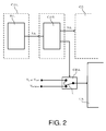
- a display device is represented in figure 2 .
- the display screen is a TFT type liquid crystal matrix screen, acronym meaning "Thin Film Transistor". This type of screen is currently the most widespread for aeronautical applications.
- the device comprises, as the device of the figure 1 , an electronic chain comprising a specific detection circuit CDS disposed between the electronic card CDL carrying the line drivers and the electronic card CP carrying the processor of the display device.
- the display device comprises an electronic CAC cut-off circuit of the image controlled by the CDS failure detection circuit such that, when the first electronic signal is representative of the malfunction of the card, the analog circuit of FIG. cutoff causes the image to be erased on the screen, the screen then being uniformly monochrome.
- the LCD display panel comprises a first EB electrode called “backplane” and an array of electrodes controlled by the electronic card “drivers” and comprising the control transistors.
- the voltage V backplane applied to the backplane in nominal operation has a first value of the order of a few volts and the minimum voltage V g-off applied to the line drivers has a second value also of a few volts.
- the analog circuit CAC cutoff comprises an analog switch I allowing, in case of malfunction of the "drivers" card, to apply to the backplane a voltage having a third value equal to the second value V g-off minus one threshold voltage V threshold , said threshold voltage being sufficient to make all the transistors uniformly passing.
- the voltage applied to the backplane may be about 7 volts below the low potential of the drivers.
- the screen technology is, for example, of the TN (Twisted Nematic) type, it becomes uniformly black. If its technology is, for example, MVA (Multi domain Vertical Alignment), IPS (In plane Switching) or AFFS (Advanced Fringe Field Switching), then it will become uniformly white. In both cases, the transition to uniformly white or black screen is very fast and fault detection is immediate.
- the analog circuit break can cut the lighting system of the display panel.
- This system generally consists of either cathode ray tubes or electroluminescent diodes. It is also possible, for example, to cut the lighting source modulation system making it possible to adjust the intensity of the sources, a system called "dimming".
- the new means according to the invention are simple to implement, require only minor adaptations of the existing electronic cards and are of great robustness and high reliability, which is the goal.
Landscapes
- Engineering & Computer Science (AREA)
- Physics & Mathematics (AREA)
- Computer Hardware Design (AREA)
- General Physics & Mathematics (AREA)
- Theoretical Computer Science (AREA)
- Power Engineering (AREA)
- Chemical & Material Sciences (AREA)
- Crystallography & Structural Chemistry (AREA)
- Control Of Indicators Other Than Cathode Ray Tubes (AREA)
- Liquid Crystal Display Device Control (AREA)
Abstract
Description
- Le domaine de l'invention est celui des dispositifs de visualisation utilisés en environnement critique. Pour un certain nombre d'applications et notamment dans le domaine des planches de bord d'aéronef, il est impératif que les dispositifs de visualisation présentent constamment des informations fiables. Ainsi, dans les visualisations de cockpit, tout affichage d'images erronées non détectable est interdit.
Les visualisations de cockpit sont le plus souvent des écrans plats matriciels. Les technologies les plus couramment employées utilisent les cristaux liquides ou les diodes électroluminescentes organiques. Les écrans mettant en oeuvre ces technologies sont appelés LCD, acronyme de « Liquid Crystal Display » ou OLED, acronyme de « Organic Light Emission Diode ». Un écran LCD ou OLED peut être considéré comme une mémoire d'image rafraîchie périodiquement par des circuits électroniques et lues par des photons. Plus précisément, l'image vidéo est commandée par deux séries de circuits appelés « drivers » commandant les lignes et les colonnes de la matrice d'affichage. L'image est présentée à l'écran d'affichage par les « drivers » des colonnes et écrite par les « drivers » des lignes.
Une panne des « drivers » colonne provoque l'écriture du même contenu sur toutes les lignes. L'image est alors constituée de traits verticaux. Dans ce cas, la panne de l'afficheur est facilement détectable et il n'y a pas de problèmes de sécurité. Par contre, si les « drivers » lignes sont en panne, l'électronique de commande ne peut plus écrire d'images et la dernière image présentée est conservée jusqu'à ce que les pixels se déchargent par des courants de fuite. Compte-tenu de la qualité des électroniques actuelles, cette décharge peut prendre plus d'une minute. Pendant ce laps de temps, le pilote ne peut pas savoir que l'image présentée est erronée et susceptible de comporter des informations fausses. Ce type de panne est souvent classée « catastrophique» par les avionneurs. Sa probabilité doit être inférieure à 10-9 et il est nécessaire de surveiller son apparition et d'avertir les pilotes du problème. - Pour résoudre ce problème, on utilise une chaîne électronique telle que représentée en
figure 1 et comportant un circuit de détection spécifique C.D.S. disposé entre la carte électronique C.D.L portant les drivers lignes D.L. et la carte électronique C.P. portant le processeur du dispositif de visualisation. Son fonctionnement est le suivant. La carte C.D.L. « drivers lignes » envoie un signal d'écriture S.E. des lignes au circuit de détection C.D.S.. Ce signal S.E. peut prendre de multiples formes. Il peut s'agir, entre autre, d'un signal représentatif du courant d'alimentation ou de l'état des sorties analogiques. Le circuit de détection traite ce signal reçu et fabrique un signal de sortie D.S. sous forme de discret électronique dont l'état est représentatif de la validité du signal reçu et donc de l'état de fonctionnement de la carte « drivers lignes ». Le signal de sortie D.S. est envoyé au processeur de l'équipement. Le logiciel du processeur traite ce signal et prend les mesures nécessaires lorsque le signal indique une panne de la carte « drivers lignes ». Il peut ainsi alerter le pilote, éteindre le dispositif de visualisation, provoquer des reconfigurations de la planche de bord,....
L'avantage principal de cette méthode est que le processeur de l'équipement gère la panne et décide de la sanction. Elle peut donc être adaptée en fonction des applications envisagées et des exigences du client pour un même équipement. Son inconvénient majeur est son coût. En effet, il est bien clair que, pour certaines applications et notamment dans le domaine aéronautique, le logiciel traitant ce type de panne doit être hautement sécurisé. II est donc très cher à développer, à faire évoluer et à valider. - Le dispositif de visualisation selon l'invention comporte un circuit de détection qui agit directement sur un circuit de coupure électrique analogique comportant très peu d'éléments électroniques et, par conséquent, d'une grande fiabilité. On résout ainsi simplement les problèmes posés par la gestion par logiciel.
- Plus précisément, l'invention a pour objet un dispositif de visualisation comportant au moins un écran matriciel, une électronique de commande de l'écran, un circuit de détection de panne et des moyens électroniques de gestion du dispositif de visualisation, l'écran étant composé de pixels disposés en lignes et en colonnes, les lignes de pixels étant commandées par une carte électronique « drivers » comportant des moyens électroniques agencés de façon à générer un premier signal électronique représentatif du bon ou du mauvais fonctionnement de ladite carte électronique « drivers », le circuit de détection de panne agencé de façon à générer, à partir du premier signal, un second signal traité par les moyens électroniques de gestion du dispositif de visualisation, caractérisé en ce que le dispositif de visualisation comporte également un circuit analogique de coupure électronique de l'image commandé par le circuit de détection de panne de façon que, lorsque le premier signal électronique est représentatif du mauvais fonctionnement de la carte, le circuit analogique de coupure provoque l'effacement de l'image sur l'écran, l'écran étant alors uniformément monochrome.
Avantageusement, l'écran étant un écran matriciel à cristaux liquides de type TFT, la dalle d'affichage à cristaux liquides comprenant au moins une première électrode dite « backplane » et une matrice d'électrodes commandées par la carte électronique « drivers » et comportant les transistors de commande, la tension appliquée à la backplane en fonctionnement nominal étant à une première valeur, la tension minimale appliquée aux drivers ligne ayant une seconde valeur, le circuit analogique de coupure comporte des moyens permettant, en cas de mauvais fonctionnement de la carte « drivers », d'appliquer à la backplane une tension ayant une troisième valeur égale à la seconde valeur diminuée d'une tension de seuil, ladite tension de seuil étant suffisante pour rendre tous les transistors uniformément passant. - L'invention sera mieux comprise et d'autres avantages apparaîtront à la lecture de la description qui va suivre donnée à titre non limitatif et grâce aux figures annexées parmi lesquelles :
- La
figure 1 déjà décrite représente un dispositif de visualisation comportant un circuit de détection de panne selon l'art antérieur ; - La
figure 2 représente un dispositif de visualisation comportant un circuit de détection de panne et un circuit de coupure analogique selon l'invention. - A titre d'exemple, un dispositif de visualisation selon l'invention est représenté en
figure 2 . Dans le cas de lafigure 2 , l'écran d'affichage est un écran matriciel à cristaux liquides de type TFT, acronyme signifiant « Thin Film Transistor ». Ce type d'écran est actuellement le plus répandu pour les applications aéronautiques. Le dispositif comporte, comme le dispositif de lafigure 1 , une chaîne électronique comportant un circuit de détection spécifique C.D.S. disposé entre la carte électronique C.D.L. portant les drivers lignes et la carte électronique C.P. portant le processeur du dispositif de visualisation. De plus, le dispositif de visualisation comporte un circuit analogique de coupure C.A.C. électronique de l'image commandé par le circuit de détection de panne C.D.S. de façon que, lorsque le premier signal électronique est représentatif du mauvais fonctionnement de la carte, le circuit analogique de coupure provoque l'effacement de l'image sur l'écran, l'écran étant alors uniformément monochrome. La dalle d'affichage à cristaux liquides comprend une première électrode E.B. dite « backplane » et une matrice d'électrodes commandées par la carte électronique « drivers » et comportant les transistors de commande. La tension Vbackplane appliquée à la backplane en fonctionnement nominal a une première valeur de l'ordre de quelques volts et la tension minimale Vg-off appliquée aux drivers ligne a une seconde valeur également de quelques volts.
Le circuit analogique de coupure C.A.C. comporte un interrupteur analogique I permettant, en cas de mauvais fonctionnement de la carte « drivers », d'appliquer à la backplane une tension ayant une troisième valeur égale à la seconde valeur Vg-off diminuée d'une tension de seuil Vseuil, ladite tension de seuil étant suffisante pour rendre tous les transistors uniformément passant. A titre d'exemple, la tension appliquée à la backplane peut être d'environ 7 volts en dessous du potentiel bas des drivers. Dans ce cas, si la technologie de l'écran est, par exemple, du type TN (Twisted Nematic), il devient uniformément noir. Si sa technologie est, par exemple, du type MVA (Multi domain Vertical Alignment), IPS (In plane Switching) ou AFFS (Advanced Fringe Field Switching), il deviendra alors uniformément blanc. Dans les deux cas, le passage à l'écran uniformément blanc ou noir est très rapide et la détection de panne est immédiate. - Il existe différentes variantes au dispositif décrit en
figure 2 . Ainsi, le circuit analogique de coupure peut couper le système d'éclairage de la dalle d'affichage. Ce système est généralement constitué soit de tubes cathodiques soit de diodes électro-luminescentes. On peut aussi, par exemple, couper le système de modulation des sources d'éclairage permettant de régler l'intensité des sources, système appelé « dimming ». - Dans tous les cas, les moyens nouveaux selon l'invention sont simples à mettre en oeuvre, ne nécessitent que des adaptations mineures des cartes électroniques existantes et sont d'une grande robustesse et d'une grande fiabilité, ce qui est le but recherché.
Claims (1)
- Dispositif de visualisation comportant au moins un écran matriciel à cristaux liquides de type TFT, une électronique de commande de l'écran, un circuit de détection de panne et des moyens électroniques de gestion du dispositif de visualisation, l'écran étant composé de pixels disposés en lignes et en colonnes, les lignes de pixels étant commandées par une carte électronique « drivers » comportant des moyens électroniques agencés de façon à générer un premier signal électronique représentatif du bon ou du mauvais fonctionnement de ladite carte électronique « drivers », la dalle d'affichage à cristaux liquides comprenant au moins une première électrode dite « backplane » et une matrice d'électrodes commandées par la carte électronique « drivers » et comportant les transistors de commande,
caractérisé en ce que, la tension appliquée à la backplane en fonctionnement nominal étant à une première valeur, la tension minimale appliquée aux drivers ligne ayant une seconde valeur, le dispositif de visualisation comporte également un circuit analogique de coupure électronique de l'image commandé par le circuit de détection de panne de façon que, lorsque le premier signal électronique est représentatif du mauvais fonctionnement de la carte, le circuit analogique de coupure comporte des moyens permettant d'appliquer à la backplane une tension ayant une troisième valeur égale à la seconde valeur diminuée d'une tension de seuil, ladite tension de seuil étant suffisante pour rendre tous les transistors uniformément passant, provoquant l'effacement de l'image sur l'écran, l'écran étant alors uniformément monochrome.
Applications Claiming Priority (1)
| Application Number | Priority Date | Filing Date | Title |
|---|---|---|---|
| FR0804538A FR2934917B1 (fr) | 2008-08-08 | 2008-08-08 | Dispositif de visualisation a ecran matriciel securise. |
Publications (2)
| Publication Number | Publication Date |
|---|---|
| EP2151810A2 true EP2151810A2 (fr) | 2010-02-10 |
| EP2151810A3 EP2151810A3 (fr) | 2010-06-23 |
Family
ID=40139235
Family Applications (1)
| Application Number | Title | Priority Date | Filing Date |
|---|---|---|---|
| EP09165124A Withdrawn EP2151810A3 (fr) | 2008-08-08 | 2009-07-10 | Dispositif de visualisation à écran matriciel securisé |
Country Status (3)
| Country | Link |
|---|---|
| US (1) | US20100033465A1 (fr) |
| EP (1) | EP2151810A3 (fr) |
| FR (1) | FR2934917B1 (fr) |
Cited By (1)
| Publication number | Priority date | Publication date | Assignee | Title |
|---|---|---|---|---|
| FR2984578A1 (fr) * | 2011-12-16 | 2013-06-21 | Thales Sa | Dispositif de visualisation securise a matrice a cristaux liquides nematiques twistes |
Families Citing this family (4)
| Publication number | Priority date | Publication date | Assignee | Title |
|---|---|---|---|---|
| FR2920908B1 (fr) * | 2007-09-07 | 2012-07-27 | Thales Sa | Dispositif de visualisation comportant un ecran a cristaux liquides a affichage securise |
| CN105574906A (zh) * | 2015-12-21 | 2016-05-11 | 苏州长风航空电子有限公司 | 一种基于预置像素的高效座舱画面设计方法 |
| CN105979092B (zh) * | 2016-05-13 | 2020-06-05 | 腾讯科技(深圳)有限公司 | 一种异常监控方法及装置 |
| CN111445452B (zh) * | 2020-03-23 | 2022-03-01 | Oppo(重庆)智能科技有限公司 | 电子产品的缺陷检测方法、装置及计算机可读存储介质 |
Family Cites Families (8)
| Publication number | Priority date | Publication date | Assignee | Title |
|---|---|---|---|---|
| JP3835967B2 (ja) * | 2000-03-03 | 2006-10-18 | アルパイン株式会社 | Lcd表示装置 |
| KR100767363B1 (ko) * | 2001-06-12 | 2007-10-17 | 삼성전자주식회사 | 액정 표시 장치 및 이의 구동 방법 |
| FR2843823B1 (fr) * | 2002-08-20 | 2006-04-21 | Thales Sa | Visualisations a cristaux liquides a commande fiabilisee |
| EP1582911A4 (fr) * | 2003-01-08 | 2007-08-08 | Toshiba Matsushita Display Tec | Affichage à cristaux liquides |
| FR2867890B1 (fr) * | 2004-03-19 | 2006-11-03 | Thales Sa | Dispositif de detection d'image figee sur un ecran a cristaux liquides |
| US7358944B2 (en) * | 2004-04-16 | 2008-04-15 | Chunghwa Picture Tubes, Ltd. | Method and system for reducing residual image effect of liquid crystal display after turned off |
| KR20060131384A (ko) * | 2005-06-16 | 2006-12-20 | 삼성에스디아이 주식회사 | 전자방출 표시장치 및 그의 구동방법 |
| JP2007286316A (ja) * | 2006-04-17 | 2007-11-01 | Seiko Epson Corp | 画像表示装置 |
-
2008
- 2008-08-08 FR FR0804538A patent/FR2934917B1/fr active Active
-
2009
- 2009-07-10 EP EP09165124A patent/EP2151810A3/fr not_active Withdrawn
- 2009-07-28 US US12/510,407 patent/US20100033465A1/en not_active Abandoned
Cited By (2)
| Publication number | Priority date | Publication date | Assignee | Title |
|---|---|---|---|---|
| FR2984578A1 (fr) * | 2011-12-16 | 2013-06-21 | Thales Sa | Dispositif de visualisation securise a matrice a cristaux liquides nematiques twistes |
| US9709833B2 (en) | 2011-12-16 | 2017-07-18 | Thales | Secure display device with twisted nematic liquid crystal matrix |
Also Published As
| Publication number | Publication date |
|---|---|
| EP2151810A3 (fr) | 2010-06-23 |
| FR2934917B1 (fr) | 2010-12-10 |
| US20100033465A1 (en) | 2010-02-11 |
| FR2934917A1 (fr) | 2010-02-12 |
Similar Documents
| Publication | Publication Date | Title |
|---|---|---|
| JP5507090B2 (ja) | 表示装置 | |
| JP2024160268A (ja) | 半導体装置 | |
| KR101315380B1 (ko) | 디스플레이장치 및 그 제어방법 | |
| US8125439B2 (en) | Liquid crystal display apparatus | |
| EP2174315B1 (fr) | Procédé integré de détection d'un defaut d'image dans un écran à cristal liquide | |
| EP2151810A2 (fr) | Dispositif de visualisation à écran matriciel securisé | |
| US8861882B2 (en) | Method and device for eliminating image blur by pixel-based processing | |
| US10311766B2 (en) | Test circuit for in-cell touch screen | |
| WO2009063797A1 (fr) | Dispositif d'affichage à cristaux liquides | |
| FR2973894A1 (fr) | Appareil d'affichage a cristaux liquides | |
| US7352345B2 (en) | Driving apparatus and method for light emitting diode display | |
| US11852930B2 (en) | Display device | |
| US20240161683A1 (en) | Display device and method for controlling light-emitting element by using memristor | |
| US8749937B2 (en) | Display device | |
| US6992747B2 (en) | Method and repairing defects in a liquid crystal display | |
| WO2015028448A1 (fr) | Ecran a matrice active a regulation de tensions d'alimentation en fonction de la temperature | |
| WO2005096261A1 (fr) | Dispositif de detection d'image figee sur un ecran a cristaux liquides | |
| FR2895529A1 (fr) | Dispositif d'affichage a cristaux liquides, procede d'excitation de celui-ci et circuit de pre-charge | |
| US20210358445A1 (en) | Drive circuit and method for display apparatus | |
| CN111508434B (zh) | 补偿oled显示屏亮度的方法及补偿装置 | |
| FR2894369A1 (fr) | Procede d'adressage ameliore pour un afficheur matriciel a cristaux liquides | |
| CN101110201B (zh) | 液晶显示器装置及其驱动方法 | |
| EP1958183B1 (fr) | Afficheur matriciel séquentiel couleur à cristaux liquides | |
| JP2007248956A (ja) | 電気光学装置および電子機器 | |
| KR100781681B1 (ko) | Lcd 백화 현상 검출 방법 및 장치 |
Legal Events
| Date | Code | Title | Description |
|---|---|---|---|
| PUAI | Public reference made under article 153(3) epc to a published international application that has entered the european phase |
Free format text: ORIGINAL CODE: 0009012 |
|
| AK | Designated contracting states |
Kind code of ref document: A2 Designated state(s): AT BE BG CH CY CZ DE DK EE ES FI FR GB GR HR HU IE IS IT LI LT LU LV MC MK MT NL NO PL PT RO SE SI SK SM TR |
|
| AX | Request for extension of the european patent |
Extension state: AL BA RS |
|
| PUAL | Search report despatched |
Free format text: ORIGINAL CODE: 0009013 |
|
| AK | Designated contracting states |
Kind code of ref document: A3 Designated state(s): AT BE BG CH CY CZ DE DK EE ES FI FR GB GR HR HU IE IS IT LI LT LU LV MC MK MT NL NO PL PT RO SE SI SK SM TR |
|
| AX | Request for extension of the european patent |
Extension state: AL BA RS |
|
| STAA | Information on the status of an ep patent application or granted ep patent |
Free format text: STATUS: THE APPLICATION IS DEEMED TO BE WITHDRAWN |
|
| 18D | Application deemed to be withdrawn |
Effective date: 20101224 |