EP2151691A2 - Systems and methods for detecting out-of-plane linear acceleration with a closed loop linear drive accelerometer - Google Patents
Systems and methods for detecting out-of-plane linear acceleration with a closed loop linear drive accelerometer Download PDFInfo
- Publication number
- EP2151691A2 EP2151691A2 EP09160944A EP09160944A EP2151691A2 EP 2151691 A2 EP2151691 A2 EP 2151691A2 EP 09160944 A EP09160944 A EP 09160944A EP 09160944 A EP09160944 A EP 09160944A EP 2151691 A2 EP2151691 A2 EP 2151691A2
- Authority
- EP
- European Patent Office
- Prior art keywords
- proof mass
- comb tines
- mass
- stator
- tines
- Prior art date
- Legal status (The legal status is an assumption and is not a legal conclusion. Google has not performed a legal analysis and makes no representation as to the accuracy of the status listed.)
- Withdrawn
Links
- 230000001133 acceleration Effects 0.000 title claims abstract description 45
- 238000000034 method Methods 0.000 title claims abstract description 8
- 239000000758 substrate Substances 0.000 claims description 20
- 230000004044 response Effects 0.000 claims description 10
- 230000009467 reduction Effects 0.000 claims description 5
- 230000000694 effects Effects 0.000 description 9
- XUIMIQQOPSSXEZ-UHFFFAOYSA-N Silicon Chemical compound [Si] XUIMIQQOPSSXEZ-UHFFFAOYSA-N 0.000 description 3
- 230000006870 function Effects 0.000 description 3
- 239000000463 material Substances 0.000 description 3
- 230000008569 process Effects 0.000 description 3
- 230000008859 change Effects 0.000 description 2
- 238000010586 diagram Methods 0.000 description 2
- 229910052710 silicon Inorganic materials 0.000 description 2
- 239000010703 silicon Substances 0.000 description 2
- 230000004888 barrier function Effects 0.000 description 1
- 238000004891 communication Methods 0.000 description 1
- 230000008878 coupling Effects 0.000 description 1
- 238000010168 coupling process Methods 0.000 description 1
- 238000005859 coupling reaction Methods 0.000 description 1
- 238000013016 damping Methods 0.000 description 1
- 238000005516 engineering process Methods 0.000 description 1
- 238000005530 etching Methods 0.000 description 1
- 239000011521 glass Substances 0.000 description 1
- 238000009413 insulation Methods 0.000 description 1
- 238000005459 micromachining Methods 0.000 description 1
- 238000000926 separation method Methods 0.000 description 1
Images

Classifications
-
- G—PHYSICS
- G01—MEASURING; TESTING
- G01P—MEASURING LINEAR OR ANGULAR SPEED, ACCELERATION, DECELERATION, OR SHOCK; INDICATING PRESENCE, ABSENCE, OR DIRECTION, OF MOVEMENT
- G01P15/00—Measuring acceleration; Measuring deceleration; Measuring shock, i.e. sudden change of acceleration
- G01P15/02—Measuring acceleration; Measuring deceleration; Measuring shock, i.e. sudden change of acceleration by making use of inertia forces using solid seismic masses
- G01P15/08—Measuring acceleration; Measuring deceleration; Measuring shock, i.e. sudden change of acceleration by making use of inertia forces using solid seismic masses with conversion into electric or magnetic values
- G01P15/125—Measuring acceleration; Measuring deceleration; Measuring shock, i.e. sudden change of acceleration by making use of inertia forces using solid seismic masses with conversion into electric or magnetic values by capacitive pick-up
-
- G—PHYSICS
- G01—MEASURING; TESTING
- G01P—MEASURING LINEAR OR ANGULAR SPEED, ACCELERATION, DECELERATION, OR SHOCK; INDICATING PRESENCE, ABSENCE, OR DIRECTION, OF MOVEMENT
- G01P15/00—Measuring acceleration; Measuring deceleration; Measuring shock, i.e. sudden change of acceleration
- G01P15/02—Measuring acceleration; Measuring deceleration; Measuring shock, i.e. sudden change of acceleration by making use of inertia forces using solid seismic masses
- G01P15/08—Measuring acceleration; Measuring deceleration; Measuring shock, i.e. sudden change of acceleration by making use of inertia forces using solid seismic masses with conversion into electric or magnetic values
- G01P15/13—Measuring acceleration; Measuring deceleration; Measuring shock, i.e. sudden change of acceleration by making use of inertia forces using solid seismic masses with conversion into electric or magnetic values by measuring the force required to restore a proofmass subjected to inertial forces to a null position
- G01P15/131—Measuring acceleration; Measuring deceleration; Measuring shock, i.e. sudden change of acceleration by making use of inertia forces using solid seismic masses with conversion into electric or magnetic values by measuring the force required to restore a proofmass subjected to inertial forces to a null position with electrostatic counterbalancing means
-
- G—PHYSICS
- G01—MEASURING; TESTING
- G01P—MEASURING LINEAR OR ANGULAR SPEED, ACCELERATION, DECELERATION, OR SHOCK; INDICATING PRESENCE, ABSENCE, OR DIRECTION, OF MOVEMENT
- G01P15/00—Measuring acceleration; Measuring deceleration; Measuring shock, i.e. sudden change of acceleration
- G01P15/02—Measuring acceleration; Measuring deceleration; Measuring shock, i.e. sudden change of acceleration by making use of inertia forces using solid seismic masses
- G01P15/08—Measuring acceleration; Measuring deceleration; Measuring shock, i.e. sudden change of acceleration by making use of inertia forces using solid seismic masses with conversion into electric or magnetic values
- G01P2015/0805—Measuring acceleration; Measuring deceleration; Measuring shock, i.e. sudden change of acceleration by making use of inertia forces using solid seismic masses with conversion into electric or magnetic values being provided with a particular type of spring-mass-system for defining the displacement of a seismic mass due to an external acceleration
- G01P2015/0822—Measuring acceleration; Measuring deceleration; Measuring shock, i.e. sudden change of acceleration by making use of inertia forces using solid seismic masses with conversion into electric or magnetic values being provided with a particular type of spring-mass-system for defining the displacement of a seismic mass due to an external acceleration for defining out-of-plane movement of the mass
- G01P2015/0825—Measuring acceleration; Measuring deceleration; Measuring shock, i.e. sudden change of acceleration by making use of inertia forces using solid seismic masses with conversion into electric or magnetic values being provided with a particular type of spring-mass-system for defining the displacement of a seismic mass due to an external acceleration for defining out-of-plane movement of the mass for one single degree of freedom of movement of the mass
- G01P2015/0831—Measuring acceleration; Measuring deceleration; Measuring shock, i.e. sudden change of acceleration by making use of inertia forces using solid seismic masses with conversion into electric or magnetic values being provided with a particular type of spring-mass-system for defining the displacement of a seismic mass due to an external acceleration for defining out-of-plane movement of the mass for one single degree of freedom of movement of the mass the mass being of the paddle type having the pivot axis between the longitudinal ends of the mass, e.g. see-saw configuration
-
- G—PHYSICS
- G01—MEASURING; TESTING
- G01P—MEASURING LINEAR OR ANGULAR SPEED, ACCELERATION, DECELERATION, OR SHOCK; INDICATING PRESENCE, ABSENCE, OR DIRECTION, OF MOVEMENT
- G01P15/00—Measuring acceleration; Measuring deceleration; Measuring shock, i.e. sudden change of acceleration
- G01P15/02—Measuring acceleration; Measuring deceleration; Measuring shock, i.e. sudden change of acceleration by making use of inertia forces using solid seismic masses
- G01P15/08—Measuring acceleration; Measuring deceleration; Measuring shock, i.e. sudden change of acceleration by making use of inertia forces using solid seismic masses with conversion into electric or magnetic values
- G01P2015/0805—Measuring acceleration; Measuring deceleration; Measuring shock, i.e. sudden change of acceleration by making use of inertia forces using solid seismic masses with conversion into electric or magnetic values being provided with a particular type of spring-mass-system for defining the displacement of a seismic mass due to an external acceleration
- G01P2015/0822—Measuring acceleration; Measuring deceleration; Measuring shock, i.e. sudden change of acceleration by making use of inertia forces using solid seismic masses with conversion into electric or magnetic values being provided with a particular type of spring-mass-system for defining the displacement of a seismic mass due to an external acceleration for defining out-of-plane movement of the mass
- G01P2015/0825—Measuring acceleration; Measuring deceleration; Measuring shock, i.e. sudden change of acceleration by making use of inertia forces using solid seismic masses with conversion into electric or magnetic values being provided with a particular type of spring-mass-system for defining the displacement of a seismic mass due to an external acceleration for defining out-of-plane movement of the mass for one single degree of freedom of movement of the mass
- G01P2015/0834—Measuring acceleration; Measuring deceleration; Measuring shock, i.e. sudden change of acceleration by making use of inertia forces using solid seismic masses with conversion into electric or magnetic values being provided with a particular type of spring-mass-system for defining the displacement of a seismic mass due to an external acceleration for defining out-of-plane movement of the mass for one single degree of freedom of movement of the mass the mass constituting a pendulum having the pivot axis disposed symmetrically between the longitudinal ends, the center of mass being shifted away from the plane of the pendulum which includes the pivot axis
-
- G—PHYSICS
- G01—MEASURING; TESTING
- G01P—MEASURING LINEAR OR ANGULAR SPEED, ACCELERATION, DECELERATION, OR SHOCK; INDICATING PRESENCE, ABSENCE, OR DIRECTION, OF MOVEMENT
- G01P15/00—Measuring acceleration; Measuring deceleration; Measuring shock, i.e. sudden change of acceleration
- G01P15/02—Measuring acceleration; Measuring deceleration; Measuring shock, i.e. sudden change of acceleration by making use of inertia forces using solid seismic masses
- G01P15/08—Measuring acceleration; Measuring deceleration; Measuring shock, i.e. sudden change of acceleration by making use of inertia forces using solid seismic masses with conversion into electric or magnetic values
- G01P2015/0862—Measuring acceleration; Measuring deceleration; Measuring shock, i.e. sudden change of acceleration by making use of inertia forces using solid seismic masses with conversion into electric or magnetic values being provided with particular means being integrated into a MEMS accelerometer structure for providing particular additional functionalities to those of a spring mass system
- G01P2015/0882—Measuring acceleration; Measuring deceleration; Measuring shock, i.e. sudden change of acceleration by making use of inertia forces using solid seismic masses with conversion into electric or magnetic values being provided with particular means being integrated into a MEMS accelerometer structure for providing particular additional functionalities to those of a spring mass system for providing damping of vibrations
Definitions
- a conventional out-of-plane Micro-Electro-Mechanical Systems (MEMS) device such as an accelerometer, may include one or more silicon proof masses mechanically coupled to and suspended from a substrate, typically glass, using one or more silicon flexures. A number of recesses etched into the substrate allow selective portions of the MEMS device to move freely within an interior portion of the MEMS device. In certain designs, substrates can be provided above and below the silicon structure to sandwich the proof masses between the two substrates. An out-of-plane MEMS device may be used to determine an out-of-plane linear acceleration by measuring exerted acceleration forces which displace portions of the proof mass.
- the moveable portion of the proof mass of an accelerometer, referred to herein as a rotor, and an adjacent, fixed portion of the MEMS device, referred to herein as a stator, are separated by a gap.
- the gap is typically filled with air or another suitable gas such that the proof mass rotor is free to move in response to acceleration of the MEMS device.
- the gap between the proof mass rotor and the fixed stator define a capacitance.
- the out-of plane linear accelerometer is accelerated in an out-of plane direction, wherein the acceleration generates a rotational torque to an unbalanced proof mass.
- a rebalancing force is applied to at least one plurality of interleaved rotor comb tines and stator comb tines, wherein the rebalancing force opposes the rotational torque, wherein the rotor comb tines are disposed at an end of the unbalanced proof mass, and wherein the stator comb tines are disposed on a stator adjacent to the end of the unbalanced proof mass.
- An amount of acceleration is then determined based upon the applied rebalancing force.
- an exemplary embodiment has an unbalanced proof mass with a first proof mass portion defined by a first mass and a second proof mass portion defined by a second mass, the second mass being different from the first mass; a plurality of first proof mass comb tines at a first end of the unbalanced proof mass; a plurality of first stator comb tines interleaved with the plurality of first proof mass comb tines, the plurality of first stator comb tines offset from the first plurality of proof mass comb tines; a plurality of second proof mass comb tines at a second end of the unbalanced proof mass; and a plurality of second stator comb tines interleaved with the plurality of second proof mass comb tines, the plurality of second stator comb tines offset from the plurality of second proof mass comb tines.
- a controller operable to apply a rebalancing force to at least one of the plurality of interleaved first rotor comb tines and first stator comb tines and the plurality of interleaved second rotor comb tines and second stator comb tines, wherein the rebalancing force opposes a rotational torque of the unbalanced proof mass generated in response to an out-of plane acceleration of the unbalance proof mass, wherein the controller is operable to determine an amount of acceleration based upon the applied rebalancing force.
- FIGURE 1 is a top side perspective view of a portion of an embodiment of a closed loop linear drive accelerometer
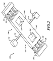
- FIGURE 2 is a bottom side perspective view of an embodiment of the proof mass of the closed loop linear drive accelerometer
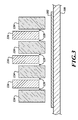
- FIGURE 3 is a cut away side view of the interleaved rotor tines and stator tines of the closed loop linear drive accelerometer.
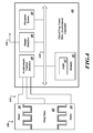
- FIGURE 4 is a block diagram of the control elements of an embodiment of the closed loop linear drive accelerometer.
- FIGURE 1 is a top side perspective view of a portion of an embodiment of a closed loop linear drive accelerometer 100 that detects out-of plane linear accelerations.
- the closed loop linear drive accelerometer 100 includes a proof mass 102, a first stator 104, a second rotor stator 106, and a portion of a substrate 108.
- Embodiments are fabricated using Micro-Electro-Mechanical Systems (MEMS) technologies.
- MEMS Micro-Electro-Mechanical Systems
- An out-of-plane linear acceleration along the Z-axis will cause the pendulous proof mass 102 to rotate.
- the closed loop mode of operation maintains the position of the proof mass 102 in a substantially fixed position when the closed loop linear drive accelerometer 100 is subjected to the out-of-plane acceleration. That is, voltages are generated and applied to the stators 104 and 106 in an exemplary embodiment to counteract torsional forces caused by the linear acceleration
- the proof mass 102 is suspended above the substrate 108 so that the proof mass 102 may rotate about the illustrated axis of rotation 110 (corresponding to the illustrated Y-axis).
- the closed loop linear drive accelerometer 100 may be interchangeably referred to as a pendulous accelerometer 100.
- Anchors 112 are bonded to the substrate 108.
- the anchors 112 may be portions of a mechanical device layer (not shown) that is bonded to the substrate 108 (and/or bonded to an upper substrate, not shown).
- Flexures 114 flexibly couple the proof mass 102 to the substrate 108, via the anchors 112.
- the flexures 114 substantially limit movement of the proof mass 102 along the X-axis and the Z-axis, yet permit rotation about the Y-axis in response to an out-of-plane acceleration (acceleration along the Z-axis).
- the flexures 114 provide electrical connectivity to the proof mass 102 so that electrical signals may be picked off of, and/or applied to, the proof mass 102.
- the stators 104, 106 are bonded to the substrate 108 such that the stators 104, 106 are held in a fixed position with respect to the proof mass 102.
- the stators 104, 106 may be additionally, or alternatively, bonded to an upper substrate (not shown).
- the stators 104, 106 may be portions of a mechanical device layer (not shown) that is bonded to the substrate 108 (and/or bonded to an upper substrate).
- the stators 104, 106 may be implemented as a plurality of separate stators.
- An exemplary embodiment of the proof mass 102 includes a first plurality of symmetrically arranged proof mass comb tines 116 formed along a first end 118 of the proof mass 102. Additionally, a second plurality of symmetrically arranged proof mass comb tines 120 are formed along an opposing second end 122 of the proof mass 102. For illustration purposes, only three proof mass comb tines 116, 120 are illustrated. In practice, many proof mass comb tines 116, 120 would be used. In alternative embodiments, the rotors may be implemented as separate groups of rotor comb tines 116, 120.
- the first stator 104 includes a corresponding number of stator comb tines 124 interleaved with the proof mass comb tines 116.
- the second stator 106 includes a number of stator comb tines 126 interleaved with the proof mass comb tines 120.
- stator comb tines 124, 126 For illustration purposes, only three stator three comb tines 124, and four stator comb tines 126, are illustrated. In practice, many stator comb tines 124, 126 would be used.
- a gap 128 separates the proof mass comb tines 116, 120 from their respective stator comb tines 124, 126.
- the gap 128 provides at least two functions. First, the gap 128 is sufficiently large that there is no frictional contact between adjacent comb tines so as to allow the proof mass 102 to rotate about its rotation axis 110 in response to linear accelerations along the Z-axis. Second, the gap 128 defines a capacitance between the proof mass comb tines 116 and the stator comb tines 124, and between the proof mass comb tines 120 and the stator comb tines 126.
- the proof mass 102 rotates about its rotation axis 110 in response to linear accelerations along the Z-axis.
- the rotation response of the proof mass 102 about the rotation axis 110 is caused by a mass imbalance between a first portion 130 of the proof mass 102 and a second portion 132 of the proof mass 102.
- the mass imbalance may be defined between the portions 130, 132 in a variety of manners, or combinations thereof.
- the length of the first portion 130 may be optionally greater than the length of the second portion 132.
- an embodiment of the closed loop linear drive accelerometer 100 computationally accounts for this effect when applying rebalancing forces, via one or more applied voltages, and/or determining the out-of-plane acceleration.
- the length of the first portion 130 is substantially the same as the length of the second portion 132.
- the location of the ends 118 and 122 of the proof mass 102 from the rotation axis 110 are substantially the same. Accordingly, the associated moment of force at the ends 118 and 122 will be substantially the same.
- FIGURE 1 illustrates an optional portion 134 of the proof mass 102 removed.
- the optional removal of material from one side of the proof mass 102 creates a mass imbalance between the portions 130, 132.
- the removed portion 134 may extend partially into the proof mass 102, or may extend all of the way through the proof mass 102.
- the removed portion 134 may be optionally filled with a material having a different density that the material of proof mass 102.
- the removed portion 134 may be interchangeably referred to as a mass reduction volume 134 or a mass reduction aperture 134.
- FIGURE 2 is a bottom side perspective view of an embodiment of the proof mass of the closed loop linear drive accelerometer 100.
- a surface area 202 of the first portion 130 of the proof mass 102 adjacent to the substrate 108 will be less than a surface area 204 of the second portion 132.
- the surface area differences may result in an undesirable imbalance in the gas dampening effect on the portion 130 and the gas dampening effect on the portion 132.
- the imbalance in the gas dampening effects between the portions 130, 132 is computationally resolved.
- the imbalance in the gas dampening effects between the portions 130, 132 may be optionally physically compensated for by removing a portion 206 from the bottom of the proof mass 102.
- the removed portion 206 may be interchangeably referred to as a gas dampening compensation volume 206.
- An area of the removed portion 206 has substantially the same area as the removed portion 134 extending through the proof mass 102. Accordingly, the surface areas 202 and 204 are substantially the same such that the gas dampening effects on the portions 130, 132 are substantially the same.
- the mass imbalance between the portions 130, 132 may be effected by making the proof mass comb tines 116 relatively smaller (less mass) than the proof mass comb tines 120. That is, the proof mass comb tines 120 may optionally have a greater mass than the proof mass comb tines 116, thereby causing the mass imbalance.
- the stator comb tines 124 may be made relatively larger (more mass) than the stator comb tines 126.
- the mass imbalance between the portions 130, 132 may be effected by removing a plurality of portions of the proof mass 102, such as along the lateral edges of the proof mass 102.
- the effect of gas damping imbalances may be mitigated by using corresponding gas dampening compensation volumes.
- FIGURE 3 is a cut away side view of the interleaved rotor tines and stator times of the closed loop linear drive accelerometer 100.
- FIGURE 3 illustrates an offset between the proof mass comb tines 116 and the stator comb tines 124.
- the proof mass comb tines 120 are offset from the stator comb tines 126.
- the offsetting of the proof mass comb tines 116, 120 from the stator comb tines 124, 126 may be implemented by offsetting the proof mass 102 from the stators 104, 106. In other embodiments, the offsetting is fabricated into the proof mass comb tines 116, 120 and the stator comb tines 124, 126 using suitable etching and/or micromachining processes.
- FIGURE 3 A portion of the substrate 108 is illustrated in FIGURE 3 .
- An optional grounding plate 302, or other suitable structure, is disposed on the substrate 108 substantially below the proof mass comb tines 116, 120 and the stator comb tines 124, 126.
- the grounding plate 302, coupled to a ground connection, provides a path for stray capacitances to ground, thereby improving the linearity of the closed loop linear drive accelerometer 100.
- FIGURE 4 is a block diagram of the control elements of an embodiment of the closed loop linear drive accelerometer controller 400. Included are a processor system 402, a memory 404, an accelerometer control interface 406, and an output interface 408.
- the processor system 402, the memory 404, the accelerometer control interface 406, and the output interface 408 are coupled to a communication bus 410, thereby providing connectivity to the above-described components.
- the above-described components may be communicatively coupled to each other in a different manner. For example, one or more of the above-described components may be directly coupled to the processor system 402, or may be coupled to the processor system 402 via intermediary components (not shown).
- a region 412 of memory 404 stores logic for controlling the closed loop linear drive accelerometer 100, and for determining the linear acceleration of the closed loop linear drive accelerometer 100.
- the accelerometer control interface 406 includes a plurality of connectors 414 that electrically couple to the proof mass 102 and the stators 104, 106.
- the connectors 414 are configured to transmit voltages, currents and/or signals between the controller 400 and the proof mass 102 and the stators 104, 106.
- the connectors may be connected in different manners, and/or to other components. Further, fewer or more connectors may be used depending upon the actual configuration of the closed loop linear drive accelerometer 100.
- the stators 104, 106 may be implemented as a plurality of separate stators, and thus, additional connectors would be required.
- the rotors may be implemented as separate groups of rotor comb tines 116, 120, and thus, additional connectors would be required.
- the output interface 408 includes one or more connectors 416 that are configured to provide the determined acceleration information to a device (not shown) which further processes the acceleration information.
- the acceleration information may be displayed on a display, stored in a remote memory, or presented in a textual format that is printable in a report or the like.
- the processor system 402 is configured to retrieve and execute the logic residing in region 412 so as to operate the closed loop linear drive accelerometer 100 in a closed loop mode of operation, also referred to as a force rebalancing mode of operation.
- the closed loop mode of operation maintains the position of the proof mass 102 in a substantially fixed position when the closed loop linear drive accelerometer 100 is subjected to an out-of-plane acceleration along either Z-axis. That is, the closed loop linear drive accelerometer controller 400 is configured to generate control signals to the proof mass comb tines 116, 120 and/or the stator comb tines 124, 126 to counteract the torsional forces caused by the linear acceleration.
- the control signal is an applied voltage.
- the closed loop linear drive accelerometer controller 400 based upon the generated control signals which counteract the torsional forces caused by the linear acceleration, also determines the amount of linear acceleration. That is, since the applied control signals which counteract the torsional forces caused by the linear acceleration are known, the amount of linear acceleration may be determined therefrom.
- control signal is applied to the interleaved comb tines 116, 124 in response to a rotational torque occurring in a first direction of rotation about the axis 110.
- Another control signal is applied to the interleaved comb tines 120, 126 in response to a rotational torque occurring in a second, opposite direction of rotation about the axis 110.
- the gap between the proof mass comb tines 116, 120 and their respective stator comb tines 124, 126 is a substantially constant value since the flexures 114 substantially prohibit motion of the proof mass 102 along wither the X-axis or the Y-axis. Accordingly, the capacitance between the proof mass comb tines 116, 120 and their respective stator comb tines 124, 126 is a function of the area of capacitive coupling between the proof mass comb tines 116, 120 and their respective stator comb tines 124, 126.
- the proof mass comb tines 116, 120 are offset from the stator comb tines 124, 126. As the proof mass comb tines 116 rotate to become more in alignment with the respective stator comb tines 124, the capacitive area between the proof mass comb tines 116 and the respective stator comb tines 124 would increase. (However, since the proof mass 102 is a fixed structure, the capacitive area between the proof mass comb tines 120 and the respective stator comb tines 126 would necessarily decrease as they are pulled out of alignment.)
- Equation (1) The capacitance between the proof mass comb tines 116, 120 and their respective stator comb tines 124, 126 is described by Equation (1) below:
- C ct x ⁇ 0 ⁇ L c ⁇ x G o ⁇ 2 ⁇ N
- ⁇ is the dielectric constant of free space
- L c is the length of the comb teeth
- x is the overlapping thickness of the comb teeth
- Go is the gap
- N the number of comb teeth.
- Equation (2) defines the stored capacitive energy between the proof mass comb tines 116, 120 and their respective stator comb tines 124, 126.
- W ct x 1 2 ⁇ C ct x ⁇ V t 2
- Equations 3 and 4 below define the forces between the proof mass comb tines 116, 120 and their respective stator comb tines 124, 126.
- Force x - d dx ⁇ W ct x
- Force ct x - 1 2 ⁇ V t 2 ⁇ ⁇ 0 ⁇ L c G o ⁇ 2 ⁇ N
- the proof mass comb tines 116, 120 and their respective stator comb tines 124, 126 are offset to provide a direction to the attractive force between the comb teeth.
- the force between the proof mass comb tines 116, 120 and their respective stator comb tines 124, 126 acts to increase the amount of overlap between the comb tines, which also increases the capacitance. (If the comb tines are in-plane with each other, then any motion of the comb teeth would only decrease the capacitance.)
- Equation (4) demonstrates that the generated force is a function of applied voltage. Accordingly, the closed loop linear drive accelerometer controller 400 may adjust the voltages applied to the stators 104, 106 to counteract the torsional forces caused by the linear acceleration.
- the proof mass 102 is illustrated as a single structure.
- the proof mass 102 may be configured, using suitable structure (not shown), to electrically isolate the proof mass comb tines 116 from the proof mass comb tines 120.
- the proof mass 102 may be in two parts and separately anchored.
- an insulation barrier or the like may be fabricated into the proof mass 102 to electrically isolate the proof mass comb tines 116 from the proof mass comb tines 120.
- the stators are electrodes disposed on the substrate 108 below the proof mass portions 130, 132.
- the alternative embodiment of the unbalanced proof mass 102 includes rotor electrodes opposing the stator electrodes. The rebalancing forces are similarly applied in response to rotational torques generated by an out-of-plane linear acceleration. The mass imbalance is effected by the mass reduction aperture 134. The imbalance in the gas dampening effects between the portions 130, 132 may be physically compensated for by the gas dampening compensation volume 206 on the bottom of the proof mass 102.
- a MEMS device is disclosed in U.S. patent 7,140,250 , entitled “MEMS Teeter-Totter Accelerometer Having Reduced Non-Linearity,” issued to Leonardson et al., and which is incorporated by reference herein in its entirety.
- the imbalance in the gas dampening effects between the portions 130, 132 may be physically compensated for by the gas dampening compensation volume 206 on the bottom of the proof mass 102.
Landscapes
- Physics & Mathematics (AREA)
- General Physics & Mathematics (AREA)
- Pressure Sensors (AREA)
- Micromachines (AREA)
Abstract
Description
- A conventional out-of-plane Micro-Electro-Mechanical Systems (MEMS) device, such as an accelerometer, may include one or more silicon proof masses mechanically coupled to and suspended from a substrate, typically glass, using one or more silicon flexures. A number of recesses etched into the substrate allow selective portions of the MEMS device to move freely within an interior portion of the MEMS device. In certain designs, substrates can be provided above and below the silicon structure to sandwich the proof masses between the two substrates. An out-of-plane MEMS device may be used to determine an out-of-plane linear acceleration by measuring exerted acceleration forces which displace portions of the proof mass.
- The moveable portion of the proof mass of an accelerometer, referred to herein as a rotor, and an adjacent, fixed portion of the MEMS device, referred to herein as a stator, are separated by a gap. The gap is typically filled with air or another suitable gas such that the proof mass rotor is free to move in response to acceleration of the MEMS device. The gap between the proof mass rotor and the fixed stator define a capacitance.
- In an open loop operated MEMS device, changes in the capacitance, induced by movement of the proof mass rotor with respect to the stator, is detectable. Based upon the detected change in capacitance, the amount of linear acceleration of the MEMS device can be determined.
- However, the movement of the proof mass rotor necessarily causes a geometry change between the rotor and the stator. Since capacitance between the rotor and the stator is proportional to the coupled rotor/stator area divided by the separation distance squared [Force = fn (Area / Distance2)], changes in the geometry between the rotor and the stator affect force in a non-linear manner. Such non-linear changes in force significantly complicate the process of determining the acceleration of the MEMS device and may introduce error in the determination of the acceleration. Accordingly, it is desirable to substantially prevent and/or control movement of the rotor with respect to the stator so that the nonlinear changes in force between the rotor and the stator are minimized.
- Systems and methods of sensing out-of-plane linear accelerations are disclosed in a closed loop operated MEMS device. In an exemplary embodiment, the out-of plane linear accelerometer is accelerated in an out-of plane direction, wherein the acceleration generates a rotational torque to an unbalanced proof mass. A rebalancing force is applied to at least one plurality of interleaved rotor comb tines and stator comb tines, wherein the rebalancing force opposes the rotational torque, wherein the rotor comb tines are disposed at an end of the unbalanced proof mass, and wherein the stator comb tines are disposed on a stator adjacent to the end of the unbalanced proof mass. An amount of acceleration is then determined based upon the applied rebalancing force.
- In accordance with further aspects, an exemplary embodiment has an unbalanced proof mass with a first proof mass portion defined by a first mass and a second proof mass portion defined by a second mass, the second mass being different from the first mass; a plurality of first proof mass comb tines at a first end of the unbalanced proof mass; a plurality of first stator comb tines interleaved with the plurality of first proof mass comb tines, the plurality of first stator comb tines offset from the first plurality of proof mass comb tines; a plurality of second proof mass comb tines at a second end of the unbalanced proof mass; and a plurality of second stator comb tines interleaved with the plurality of second proof mass comb tines, the plurality of second stator comb tines offset from the plurality of second proof mass comb tines. A controller operable to apply a rebalancing force to at least one of the plurality of interleaved first rotor comb tines and first stator comb tines and the plurality of interleaved second rotor comb tines and second stator comb tines, wherein the rebalancing force opposes a rotational torque of the unbalanced proof mass generated in response to an out-of plane acceleration of the unbalance proof mass, wherein the controller is operable to determine an amount of acceleration based upon the applied rebalancing force.
- Preferred and alternative embodiments are described in detail below with reference to the following drawings:
-
FIGURE 1 is a top side perspective view of a portion of an embodiment of a closed loop linear drive accelerometer; -
FIGURE 2 is a bottom side perspective view of an embodiment of the proof mass of the closed loop linear drive accelerometer; -
FIGURE 3 is a cut away side view of the interleaved rotor tines and stator tines of the closed loop linear drive accelerometer; and -
FIGURE 4 is a block diagram of the control elements of an embodiment of the closed loop linear drive accelerometer. -
FIGURE 1 is a top side perspective view of a portion of an embodiment of a closed looplinear drive accelerometer 100 that detects out-of plane linear accelerations. The closed looplinear drive accelerometer 100 includes aproof mass 102, afirst stator 104, asecond rotor stator 106, and a portion of asubstrate 108. Embodiments are fabricated using Micro-Electro-Mechanical Systems (MEMS) technologies. - An out-of-plane linear acceleration along the Z-axis will cause the
pendulous proof mass 102 to rotate. The closed loop mode of operation maintains the position of theproof mass 102 in a substantially fixed position when the closed looplinear drive accelerometer 100 is subjected to the out-of-plane acceleration. That is, voltages are generated and applied to thestators - The
proof mass 102 is suspended above thesubstrate 108 so that theproof mass 102 may rotate about the illustrated axis of rotation 110 (corresponding to the illustrated Y-axis). The closed looplinear drive accelerometer 100 may be interchangeably referred to as apendulous accelerometer 100. -
Anchors 112 are bonded to thesubstrate 108. In some embodiments, theanchors 112 may be portions of a mechanical device layer (not shown) that is bonded to the substrate 108 (and/or bonded to an upper substrate, not shown). -
Flexures 114 flexibly couple theproof mass 102 to thesubstrate 108, via theanchors 112. Thus, theflexures 114 substantially limit movement of theproof mass 102 along the X-axis and the Z-axis, yet permit rotation about the Y-axis in response to an out-of-plane acceleration (acceleration along the Z-axis). In some embodiments, theflexures 114 provide electrical connectivity to theproof mass 102 so that electrical signals may be picked off of, and/or applied to, theproof mass 102. - In the exemplary embodiment, the
stators substrate 108 such that thestators proof mass 102. In some embodiments, thestators stators stators - An exemplary embodiment of the
proof mass 102 includes a first plurality of symmetrically arranged proofmass comb tines 116 formed along afirst end 118 of theproof mass 102. Additionally, a second plurality of symmetrically arranged proofmass comb tines 120 are formed along an opposingsecond end 122 of theproof mass 102. For illustration purposes, only three proofmass comb tines mass comb tines rotor comb tines - The
first stator 104 includes a corresponding number ofstator comb tines 124 interleaved with the proofmass comb tines 116. Similarly, thesecond stator 106 includes a number ofstator comb tines 126 interleaved with the proofmass comb tines 120. For illustration purposes, only three stator threecomb tines 124, and fourstator comb tines 126, are illustrated. In practice, manystator comb tines - A
gap 128 separates the proofmass comb tines stator comb tines gap 128 provides at least two functions. First, thegap 128 is sufficiently large that there is no frictional contact between adjacent comb tines so as to allow theproof mass 102 to rotate about itsrotation axis 110 in response to linear accelerations along the Z-axis. Second, thegap 128 defines a capacitance between the proofmass comb tines 116 and thestator comb tines 124, and between the proofmass comb tines 120 and thestator comb tines 126. - As noted above, the
proof mass 102 rotates about itsrotation axis 110 in response to linear accelerations along the Z-axis. The rotation response of theproof mass 102 about therotation axis 110 is caused by a mass imbalance between afirst portion 130 of theproof mass 102 and asecond portion 132 of theproof mass 102. Thefirst portion 130 and thesecond portion 132 are defined by therotation axis 110. Since the masses of theportions proof mass 102 that are applied to thefirst portion 130 will be different from a force applied to thesecond portion 132. (Generally, it is known that Force = Mass times Acceleration. Thus, a linear acceleration along the Z-axis will result in different forces on theportions first portion 130 and the force exerted on thesecond portion 132, which tends to rotate theproof mass 102 about its rotation axis 110). - The mass imbalance may be defined between the
portions first portion 130 may be optionally greater than the length of thesecond portion 132. However, in view of the location of thefirst end 118 of theproof mass 102 being farther away from therotation axis 110 than the location of thesecond end 122, the associated moment of force at theend 118 will be different from the moment of force atend 120. Accordingly, an embodiment of the closed looplinear drive accelerometer 100 computationally accounts for this effect when applying rebalancing forces, via one or more applied voltages, and/or determining the out-of-plane acceleration. - In another embodiment, the length of the
first portion 130 is substantially the same as the length of thesecond portion 132. Thus, the location of theends proof mass 102 from therotation axis 110 are substantially the same. Accordingly, the associated moment of force at theends - The mass imbalance in embodiments where the location of the
ends proof mass 102 are substantially equidistant from therotation axis 110 may be effected in one or more different manners.FIGURE 1 illustrates anoptional portion 134 of theproof mass 102 removed. The optional removal of material from one side of theproof mass 102 creates a mass imbalance between theportions portion 134 may extend partially into theproof mass 102, or may extend all of the way through theproof mass 102. In some embodiments, the removedportion 134 may be optionally filled with a material having a different density that the material ofproof mass 102. The removedportion 134 may be interchangeably referred to as amass reduction volume 134 or amass reduction aperture 134. -
FIGURE 2 is a bottom side perspective view of an embodiment of the proof mass of the closed looplinear drive accelerometer 100. In embodiments where the removedportion 134 extends through theproof mass 102, asurface area 202 of thefirst portion 130 of theproof mass 102 adjacent to thesubstrate 108 will be less than asurface area 204 of thesecond portion 132. The surface area differences may result in an undesirable imbalance in the gas dampening effect on theportion 130 and the gas dampening effect on theportion 132. In some embodiments, the imbalance in the gas dampening effects between theportions - In the illustrated embodiment of
FIGURE 2 , the imbalance in the gas dampening effects between theportions portion 206 from the bottom of theproof mass 102. The removedportion 206 may be interchangeably referred to as a gas dampeningcompensation volume 206. An area of the removedportion 206 has substantially the same area as the removedportion 134 extending through theproof mass 102. Accordingly, thesurface areas portions - Alternatively, or additionally, the mass imbalance between the
portions mass comb tines 116 relatively smaller (less mass) than the proofmass comb tines 120. That is, the proofmass comb tines 120 may optionally have a greater mass than the proofmass comb tines 116, thereby causing the mass imbalance. To maintain the geometries of thegaps 128 such that thegaps 128 are substantially the same on both ends 118 and 122 of theproof mass 102, thestator comb tines 124 may be made relatively larger (more mass) than thestator comb tines 126. - Alternatively, or additionally, the mass imbalance between the
portions proof mass 102, such as along the lateral edges of theproof mass 102. The effect of gas damping imbalances may be mitigated by using corresponding gas dampening compensation volumes. -
FIGURE 3 is a cut away side view of the interleaved rotor tines and stator times of the closed looplinear drive accelerometer 100.FIGURE 3 illustrates an offset between the proofmass comb tines 116 and thestator comb tines 124. Similarly, the proofmass comb tines 120 are offset from thestator comb tines 126. The offsetting of the proofmass comb tines stator comb tines proof mass 102 from thestators mass comb tines stator comb tines - A portion of the
substrate 108 is illustrated inFIGURE 3 . Anoptional grounding plate 302, or other suitable structure, is disposed on thesubstrate 108 substantially below the proofmass comb tines stator comb tines grounding plate 302, coupled to a ground connection, provides a path for stray capacitances to ground, thereby improving the linearity of the closed looplinear drive accelerometer 100. -
FIGURE 4 is a block diagram of the control elements of an embodiment of the closed loop lineardrive accelerometer controller 400. Included are aprocessor system 402, a memory 404, anaccelerometer control interface 406, and anoutput interface 408. Theprocessor system 402, the memory 404, theaccelerometer control interface 406, and theoutput interface 408 are coupled to acommunication bus 410, thereby providing connectivity to the above-described components. In alternative embodiments of the closed looplinear drive accelerometer 100, the above-described components may be communicatively coupled to each other in a different manner. For example, one or more of the above-described components may be directly coupled to theprocessor system 402, or may be coupled to theprocessor system 402 via intermediary components (not shown). Aregion 412 of memory 404 stores logic for controlling the closed looplinear drive accelerometer 100, and for determining the linear acceleration of the closed looplinear drive accelerometer 100. - The
accelerometer control interface 406 includes a plurality ofconnectors 414 that electrically couple to theproof mass 102 and thestators connectors 414 are configured to transmit voltages, currents and/or signals between thecontroller 400 and theproof mass 102 and thestators linear drive accelerometer 100. For example, thestators rotor comb tines - The
output interface 408 includes one ormore connectors 416 that are configured to provide the determined acceleration information to a device (not shown) which further processes the acceleration information. For example, the acceleration information may be displayed on a display, stored in a remote memory, or presented in a textual format that is printable in a report or the like. - The
processor system 402 is configured to retrieve and execute the logic residing inregion 412 so as to operate the closed looplinear drive accelerometer 100 in a closed loop mode of operation, also referred to as a force rebalancing mode of operation. - The closed loop mode of operation maintains the position of the
proof mass 102 in a substantially fixed position when the closed looplinear drive accelerometer 100 is subjected to an out-of-plane acceleration along either Z-axis. That is, the closed loop lineardrive accelerometer controller 400 is configured to generate control signals to the proofmass comb tines stator comb tines - The closed loop linear
drive accelerometer controller 400, based upon the generated control signals which counteract the torsional forces caused by the linear acceleration, also determines the amount of linear acceleration. That is, since the applied control signals which counteract the torsional forces caused by the linear acceleration are known, the amount of linear acceleration may be determined therefrom. - In an exemplary embodiment, the control signal is applied to the interleaved
comb tines axis 110. Another control signal is applied to the interleavedcomb tines axis 110. - In practice, the gap between the proof
mass comb tines stator comb tines flexures 114 substantially prohibit motion of theproof mass 102 along wither the X-axis or the Y-axis. Accordingly, the capacitance between the proofmass comb tines stator comb tines mass comb tines stator comb tines - As noted above, the proof
mass comb tines stator comb tines mass comb tines 116 rotate to become more in alignment with the respectivestator comb tines 124, the capacitive area between the proofmass comb tines 116 and the respectivestator comb tines 124 would increase. (However, since theproof mass 102 is a fixed structure, the capacitive area between the proofmass comb tines 120 and the respectivestator comb tines 126 would necessarily decrease as they are pulled out of alignment.) - The capacitance between the proof
mass comb tines stator comb tines 
In Equation (1), ε is the dielectric constant of free space, Lc is the length of the comb teeth, x is the overlapping thickness of the comb teeth, Go is the gap, and N is the number of comb teeth. - Equation (2) below defines the stored capacitive energy between the proof
mass comb tines stator comb tines 
- Equations 3 and 4 below define the forces between the proof
mass comb tines stator comb tines 

- Accordingly, the proof
mass comb tines stator comb tines mass comb tines stator comb tines - Equation (4) demonstrates that the generated force is a function of applied voltage. Accordingly, the closed loop linear
drive accelerometer controller 400 may adjust the voltages applied to thestators - For convenience, the
proof mass 102 is illustrated as a single structure. In some embodiments, theproof mass 102 may be configured, using suitable structure (not shown), to electrically isolate the proofmass comb tines 116 from the proofmass comb tines 120. For example, theproof mass 102 may be in two parts and separately anchored. Or, an insulation barrier or the like (not shown) may be fabricated into theproof mass 102 to electrically isolate the proofmass comb tines 116 from the proofmass comb tines 120. - In some alternative embodiments of a MEMS accelerometer, such as disclosed in
U.S. patent 7,146,856 , entitled "Dynamically Balanced Capacitive Pick-Off Accelerometer," issued to Malametz, and which is incorporated by reference herein in its entirety, the stators are electrodes disposed on thesubstrate 108 below the proofmass portions unbalanced proof mass 102 includes rotor electrodes opposing the stator electrodes. The rebalancing forces are similarly applied in response to rotational torques generated by an out-of-plane linear acceleration. The mass imbalance is effected by themass reduction aperture 134. The imbalance in the gas dampening effects between theportions compensation volume 206 on the bottom of theproof mass 102. - In another exemplary embodiment, a MEMS device is disclosed in
U.S. patent 7,140,250 , entitled "MEMS Teeter-Totter Accelerometer Having Reduced Non-Linearity," issued to Leonardson et al., and which is incorporated by reference herein in its entirety. The imbalance in the gas dampening effects between theportions compensation volume 206 on the bottom of theproof mass 102. - While the preferred embodiment of the invention has been illustrated and described, as noted above, many changes can be made without departing from the spirit and scope of the invention. Accordingly, the scope of the invention is not limited by the disclosure of the preferred embodiment. Instead, the invention should be determined entirely by reference to the claims that follow.
- The embodiments of the invention in which an exclusive property or privilege is claimed are defined as follows:
Claims (10)
- A closed loop linear drive accelerometer (100), comprising:an unbalanced proof mass (102) with a first proof mass portion (130) defined by a first mass and a second proof mass portion (132) defined by a second mass, the second mass being different from the first mass;a plurality of first proof mass comb tines (116) at a first end of the unbalanced proof mass (102);a plurality of first stator comb tines (124) interleaved with the plurality of first proof mass comb tines (116), the plurality of first stator comb tines (124) offset from the plurality of first proof mass comb tines (116);a plurality of second proof mass comb tines (120) at a second end of the unbalanced proof mass (102);a plurality of second stator comb tines (126) interleaved with the plurality of second proof mass comb tines (120), the plurality of second stator comb tines (126) offset from the plurality of second proof mass comb tines (120); anda controller (400) operable to apply a rebalancing force to at least one of the plurality of interleaved first proof mass comb tines (116) and first stator comb tines (124) and the plurality of interleaved second proof mass comb tines and second stator comb tines (126), wherein the rebalancing force opposes a rotational torque of the unbalanced proof mass (102) generated in response to an out-of-plane acceleration of the unbalanced proof mass (102), wherein the controller (400) is operable to determine an amount of acceleration based upon the applied rebalancing force.
- The closed loop linear drive accelerometer (100) of Claim 1, further comprising:at least one flexure (114) configured to couple the unbalanced proof mass (102) to an anchor (112), and configured to define an axis of rotation between the first proof mass portion (130) and the second proof mass portion (132), wherein the rotational torque is about the axis of rotation (110).
- The closed loop linear drive accelerometer (100) of Claim 1, wherein a first gap defines a first capacitance between the plurality of first proof mass comb tines (116) and the plurality of first stator comb tines (124), wherein a second gap defines a second capacitance between the plurality of second proof mass comb tines (120) and the plurality of second stator comb tines (126), and wherein a linear out-of-plane acceleration of the unbalanced proof mass generates the rotational torque changes the first capacitance and the second capacitance.
- The closed loop linear drive accelerometer (100) of Claim 1, wherein the controller (400) comprises:a closed loop linear drive accelerometer controller electrically coupled to the plurality of first stator comb tines (124) and the plurality of second stator comb tines (126), and configured to apply a rebalancing voltage to at least one of the plurality of first stator comb tines (124) and the plurality of second stator comb tines (126) that substantially counteracts a rotational torque of the unbalanced proof mass (102).
- The closed loop linear drive accelerometer of Claim 1, further comprising:a ground plate (302) disposed below at least the plurality of first proof mass comb tines (116) and the plurality of first stator comb tines (124).
- The closed loop linear drive accelerometer (100) of Claim 1, wherein a first tine mass of the first proof mass comb tines (116) is greater than a second tine mass of the first stator comb tines (124), and wherein a third tine mass of the second proof mass comb tines (120) is less than a fourth tine mass of the second stator comb tines (126), such that the first mass of the first proof mass portion (130) is greater than the second mass of the second proof mass portion (132).
- The closed loop linear drive accelerometer (100) of Claim 1, further comprising:a gas dampening compensation volume disposed in the first proof mass portion (130) such that the first mass of the first proof mass portion is less than the second mass of the second proof mass portion (132); anda gas dampening compensation volume disposed on a side of the second proof mass adjacent to a substrate (108), wherein an area of the gas dampening compensation volume is substantially equal to an area of the mass reduction aperture,wherein a gas dampening of the first proof mass portion (130) is substantially equal to a gas dampening of the second proof mass portion (132).
- A Micro-Electro-Mechanical Systems (MEMS) device comprising:an unbalanced proof mass (102) with a first proof mass portion (130) defined by a first mass and a second proof mass portion (132) defined by a second mass, the second mass being different from the first mass;a gas dampening compensation volume disposed in the first proof mass portion (130) such that the first mass of the first proof mass portion (130) is less than the second mass of the second proof mass portion (132); anda gas dampening compensation volume disposed on a side of the second proof mass portion (132) adjacent to a substrate (108), wherein an area of the gas dampening compensation volume is substantially equal to an area of the mass reduction aperture,wherein a gas dampening of the first proof mass portion (130) is substantially equal to a gas dampening of the second proof mass portion (132).
- The MEMS device of Claim 8, further comprising:a plurality of first proof mass comb tines (116) at a first end of the unbalanced proof mass (102);a plurality of first stator comb tines (124) interleaved with the plurality of first proof mass comb tines (116), the plurality of first stator comb tines (124) offset from the first plurality of proof mass comb tines (124);a plurality of second proof mass comb tines (120) at a second end of the unbalanced proof mass (102); anda plurality of second stator comb tines (126) interleaved with the plurality of second proof mass comb tines (120), the plurality of second stator comb tines (126) offset from the plurality of second proof mass comb tines (120).
- A method that determines an out-of-plane acceleration of an accelerometer (100), the method comprising:accelerating the accelerometer (100) in an out-of-plane direction, wherein the acceleration generates a rotational torque to an unbalanced proof mass (102);applying a rebalancing force to at least one plurality of interleaved rotor comb tines (116, 120) and stator comb tines (124, 126), wherein the rebalancing force opposes the rotational torque, wherein the rotor comb tines (116, 120) are disposed at an end of the unbalanced proof mass (102), and wherein the stator comb tines (124, 126) are disposed on a stator (104, 106) adjacent to the end of the unbalanced proof mass (102); anddetermining an amount of acceleration based upon the applied rebalancing force.
Applications Claiming Priority (1)
| Application Number | Priority Date | Filing Date | Title |
|---|---|---|---|
| US12/183,678 US8171793B2 (en) | 2008-07-31 | 2008-07-31 | Systems and methods for detecting out-of-plane linear acceleration with a closed loop linear drive accelerometer |
Publications (2)
| Publication Number | Publication Date |
|---|---|
| EP2151691A2 true EP2151691A2 (en) | 2010-02-10 |
| EP2151691A3 EP2151691A3 (en) | 2012-05-09 |
Family
ID=41314646
Family Applications (1)
| Application Number | Title | Priority Date | Filing Date |
|---|---|---|---|
| EP09160944A Withdrawn EP2151691A3 (en) | 2008-07-31 | 2009-05-22 | Systems and methods for detecting out-of-plane linear acceleration with a closed loop linear drive accelerometer |
Country Status (3)
| Country | Link |
|---|---|
| US (1) | US8171793B2 (en) |
| EP (1) | EP2151691A3 (en) |
| JP (2) | JP5770968B2 (en) |
Cited By (8)
| Publication number | Priority date | Publication date | Assignee | Title |
|---|---|---|---|---|
| EP2362231A1 (en) * | 2010-02-19 | 2011-08-31 | Honeywell International Inc. | Out-of-plane comb-drive accelerometer |
| WO2012052238A1 (en) * | 2010-10-20 | 2012-04-26 | Robert Bosch Gmbh | Micromechanical device for measuring an acceleration, a pressure or the like and a corresponding method |
| EP2464981A4 (en) * | 2009-08-13 | 2014-01-22 | Meggitt Orange County Inc | Proof mass for maximized, bi-directional and symmetric damping in high g-range acceleration sensors |
| EP2717060A1 (en) * | 2012-10-08 | 2014-04-09 | Northrop Grumman Systems Corporation | Dynamic self-calibration of an accelerometer system |
| EP3217181A1 (en) * | 2016-03-11 | 2017-09-13 | Commissariat à l'énergie atomique et aux énergies alternatives | Damped linear accelerometer |
| IT201900000190A1 (en) * | 2019-01-08 | 2020-07-08 | St Microelectronics Srl | MEMS DEVICE WITH OPTIMIZED GEOMETRY FOR REDUCING THE OFFSET DUE TO THE RADIOMETRIC EFFECT |
| DE102010039069B4 (en) | 2010-08-09 | 2023-08-24 | Robert Bosch Gmbh | Acceleration sensor with a damping device |
| DE102011011160B4 (en) | 2011-01-05 | 2024-01-11 | Robert Bosch Gmbh | Micromechanical component and manufacturing process for a micromechanical component |
Families Citing this family (40)
| Publication number | Priority date | Publication date | Assignee | Title |
|---|---|---|---|---|
| KR101283683B1 (en) * | 2009-12-14 | 2013-07-08 | 한국전자통신연구원 | Vertical Accelerometer |
| EP2541971B1 (en) | 2010-02-24 | 2020-08-12 | Panasonic Intellectual Property Management Co., Ltd. | Sound processing device and sound processing method |
| DE102010039240B4 (en) * | 2010-08-12 | 2021-06-24 | Robert Bosch Gmbh | Accelerometer |
| DE102010039236B4 (en) * | 2010-08-12 | 2023-06-29 | Robert Bosch Gmbh | Sensor arrangement and method for adjusting a sensor arrangement |
| JP2012163507A (en) * | 2011-02-09 | 2012-08-30 | Mitsubishi Electric Corp | Acceleration sensor |
| US9229026B2 (en) * | 2011-04-13 | 2016-01-05 | Northrop Grumman Guaidance and Electronics Company, Inc. | Accelerometer systems and methods |
| DE102011076551B4 (en) * | 2011-05-26 | 2024-02-22 | Robert Bosch Gmbh | Inertial sensor |
| JP2013117396A (en) * | 2011-12-01 | 2013-06-13 | Denso Corp | Acceleration sensor |
| TWI616395B (en) * | 2012-01-12 | 2018-03-01 | 村田電子公司 | Acceleration sensor structure and use thereof |
| CN102620726B (en) * | 2012-04-04 | 2014-10-29 | 西北工业大学 | Double-closed-loop control circuit of micromechanical gyroscope |
| US9290067B2 (en) | 2012-08-30 | 2016-03-22 | Freescale Semiconductor, Inc. | Pressure sensor with differential capacitive output |
| US9470709B2 (en) | 2013-01-28 | 2016-10-18 | Analog Devices, Inc. | Teeter totter accelerometer with unbalanced mass |
| US9297825B2 (en) | 2013-03-05 | 2016-03-29 | Analog Devices, Inc. | Tilt mode accelerometer with improved offset and noise performance |
| JP2014190807A (en) * | 2013-03-27 | 2014-10-06 | Denso Corp | Acceleration sensor |
| US9383384B2 (en) | 2013-05-31 | 2016-07-05 | Honeywell International Inc. | Extended-range closed-loop accelerometer |
| DE102013216907A1 (en) * | 2013-08-26 | 2015-02-26 | Robert Bosch Gmbh | Micromechanical sensor |
| CN103675348B (en) * | 2013-12-09 | 2015-10-21 | 南京信息工程大学 | Z axis capacitance type micromechanical accelerometer |
| US20150268269A1 (en) * | 2014-03-20 | 2015-09-24 | Freescale Semiconductor, Inc. | Sensor with combined sense elements for multiple axis sensing |
| US10073113B2 (en) | 2014-12-22 | 2018-09-11 | Analog Devices, Inc. | Silicon-based MEMS devices including wells embedded with high density metal |
| TWI580967B (en) * | 2014-12-29 | 2017-05-01 | 財團法人國家實驗研究院 | Monolithic z-axis displacement cmos mems accelerometer |
| US10436812B2 (en) | 2015-03-20 | 2019-10-08 | Nxp Usa, Inc. | Micro-electro-mechanical acceleration sensor device |
| US10078098B2 (en) | 2015-06-23 | 2018-09-18 | Analog Devices, Inc. | Z axis accelerometer design with offset compensation |
| JP6507999B2 (en) * | 2015-11-04 | 2019-05-08 | 株式会社豊田中央研究所 | MEMS sensor |
| CN106809799B (en) * | 2015-11-27 | 2018-07-20 | 上海微联传感科技有限公司 | Acceleration transducer and its manufacturing method |
| JP2019003113A (en) * | 2017-06-16 | 2019-01-10 | キヤノン株式会社 | Image forming apparatus having optical print head |
| CN107966588B (en) * | 2017-11-21 | 2020-04-03 | 中国电子产品可靠性与环境试验研究所 | Method and device for evaluating nonlinear characteristics of accelerometer |
| US11733263B2 (en) | 2018-09-21 | 2023-08-22 | Analog Devices, Inc. | 3-axis accelerometer |
| CN113272657B (en) * | 2019-01-24 | 2024-09-13 | 乌第有限合伙公司 | Particle-based accelerometers |
| JP7134931B2 (en) * | 2019-08-28 | 2022-09-12 | 株式会社東芝 | sensor |
| JP7383978B2 (en) * | 2019-10-23 | 2023-11-21 | セイコーエプソン株式会社 | Physical quantity sensors, electronic devices and moving objects |
| CN110824196B (en) * | 2019-11-18 | 2023-10-03 | 中国兵器工业集团第二一四研究所苏州研发中心 | Stress-insensitive MEMS capacitive Z-axis accelerometer |
| WO2022264816A1 (en) * | 2021-06-16 | 2022-12-22 | ローム株式会社 | Acceleration sensor |
| JP7793933B2 (en) * | 2021-10-29 | 2026-01-06 | セイコーエプソン株式会社 | Physical Quantity Sensors and Inertial Measurement Units |
| JP7855846B2 (en) * | 2021-10-29 | 2026-05-11 | セイコーエプソン株式会社 | Physical quantity sensors and inertial measurement devices |
| CN114279442A (en) * | 2021-12-30 | 2022-04-05 | 中国电子科技集团公司第十三研究所 | Micro-mechanical detection structure to prevent electrostatic pull-in |
| EP4249923A1 (en) * | 2022-03-25 | 2023-09-27 | Murata Manufacturing Co., Ltd. | Improved accelerometer element for detecting out-of-plane accelerations |
| JP2023152416A (en) * | 2022-04-04 | 2023-10-17 | セイコーエプソン株式会社 | Inertial sensor and inertial measurement module |
| US11906693B2 (en) | 2022-05-30 | 2024-02-20 | Huazhong University Of Science And Technology | Variable-area comb capacitor-based MEMS relative gravimeter probe and gravimeter |
| CN115061213B (en) * | 2022-05-30 | 2025-07-29 | 华中科技大学 | MEMS relative gravimeter probe and gravimeter based on variable area comb tooth capacitance |
| EP4428542B1 (en) * | 2023-03-07 | 2025-06-18 | Murata Manufacturing Co., Ltd. | In-plane and out-of-plane accelerometer |
Citations (4)
| Publication number | Priority date | Publication date | Assignee | Title |
|---|---|---|---|---|
| WO1997004283A2 (en) | 1995-07-20 | 1997-02-06 | Cornell Research Foundation, Inc. | Microfabricated torsional cantilevers for sensitive force detection |
| US6230566B1 (en) | 1999-10-01 | 2001-05-15 | The Regents Of The University Of California | Micromachined low frequency rocking accelerometer with capacitive pickoff |
| US20060185433A1 (en) | 2005-02-18 | 2006-08-24 | Honeywell International, Inc. | MEMS teeter-totter accelerometer having reduced non-linearty |
| US20090031809A1 (en) | 2007-08-03 | 2009-02-05 | Freescale Semiconductor, Inc. | Symmetrical differential capacitive sensor and method of making same |
Family Cites Families (30)
| Publication number | Priority date | Publication date | Assignee | Title |
|---|---|---|---|---|
| JPS6163167U (en) * | 1984-09-29 | 1986-04-28 | ||
| US5404749A (en) * | 1993-04-07 | 1995-04-11 | Ford Motor Company | Boron doped silicon accelerometer sense element |
| CA2149933A1 (en) * | 1994-06-29 | 1995-12-30 | Robert M. Boysel | Micro-mechanical accelerometers with improved detection circuitry |
| JP3139305B2 (en) * | 1994-08-24 | 2001-02-26 | 株式会社村田製作所 | Capacitive acceleration sensor |
| US5596144A (en) * | 1995-08-04 | 1997-01-21 | Delco Electronics Corporation | Piezoresistive force rebalance accelerometer |
| DE19541388A1 (en) * | 1995-11-07 | 1997-05-15 | Telefunken Microelectron | Micromechanical acceleration sensor |
| DE19750350C1 (en) * | 1997-11-13 | 1999-08-05 | Univ Dresden Tech | Three-dimensional chip acceleration sensor |
| US6000287A (en) * | 1998-08-28 | 1999-12-14 | Ford Motor Company | Capacitor center of area sensitivity in angular motion micro-electromechanical systems |
| US6481283B1 (en) | 1999-04-05 | 2002-11-19 | Milli Sensor Systems & Actuators, Inc. | Coriolis oscillating gyroscopic instrument |
| EP1243930A1 (en) * | 2001-03-08 | 2002-09-25 | EADS Deutschland Gmbh | Micromechanical capacitive accelerometer |
| US7870788B2 (en) * | 2002-01-25 | 2011-01-18 | Kinemetrics, Inc. | Fabrication process and package design for use in a micro-machined seismometer or other device |
| JP4174351B2 (en) * | 2002-03-15 | 2008-10-29 | 株式会社豊田中央研究所 | Device having movable electrode, movable mirror device, vibrating gyroscope, and manufacturing method thereof |
| AU2003226083A1 (en) * | 2002-03-26 | 2003-10-13 | The Charles Stark Draper Laboratory, Inc. | Microelectromechanical sensors having reduced signal bias errors and methods of manufacturing the same |
| US6841992B2 (en) | 2003-02-18 | 2005-01-11 | Honeywell International, Inc. | MEMS enhanced capacitive pick-off and electrostatic rebalance electrode placement |
| US6935175B2 (en) | 2003-11-20 | 2005-08-30 | Honeywell International, Inc. | Capacitive pick-off and electrostatic rebalance accelerometer having equalized gas damping |
| EP2284545B1 (en) * | 2004-01-07 | 2018-08-08 | Northrop Grumman Corporation | Coplanar proofmasses employable to sense acceleration along three axes |
| US7146856B2 (en) | 2004-06-07 | 2006-12-12 | Honeywell International, Inc. | Dynamically balanced capacitive pick-off accelerometer |
| JP3869438B2 (en) * | 2004-08-09 | 2007-01-17 | サンテック株式会社 | MEMS device, manufacturing method thereof, and optical device |
| US7069784B1 (en) | 2004-12-29 | 2006-07-04 | Honeywell International Inc. | Pendulous in-plane MEMS accelerometer device |
| US20060207327A1 (en) * | 2005-03-16 | 2006-09-21 | Zarabadi Seyed R | Linear accelerometer |
| JP4453587B2 (en) * | 2005-03-24 | 2010-04-21 | 株式会社デンソー | Acceleration sensor |
| US7210352B2 (en) * | 2005-06-14 | 2007-05-01 | Innovative Micro Technology | MEMS teeter-totter apparatus with curved beam and method of manufacture |
| FI119299B (en) * | 2005-06-17 | 2008-09-30 | Vti Technologies Oy | Process for manufacturing capacitive acceleration sensor and capacitive acceleration sensor |
| US7516661B2 (en) | 2006-02-23 | 2009-04-14 | Honeywell International Inc. | Z offset MEMS device |
| FR2898683B1 (en) * | 2006-03-14 | 2008-05-23 | Commissariat Energie Atomique | TRIAXIAL MEMBRANE ACCELEROMETER |
| JP4600345B2 (en) * | 2006-04-28 | 2010-12-15 | パナソニック電工株式会社 | Capacitive sensor |
| US7469588B2 (en) * | 2006-05-16 | 2008-12-30 | Honeywell International Inc. | MEMS vertical comb drive with improved vibration performance |
| US7552637B2 (en) * | 2006-09-19 | 2009-06-30 | Honeywell International Inc. | Torque driving circuit |
| US7487678B2 (en) * | 2006-12-13 | 2009-02-10 | Honeywell International Inc. | Z offset MEMS devices and methods |
| US8079262B2 (en) * | 2007-10-26 | 2011-12-20 | Rosemount Aerospace Inc. | Pendulous accelerometer with balanced gas damping |
-
2008
- 2008-07-31 US US12/183,678 patent/US8171793B2/en active Active
-
2009
- 2009-05-22 EP EP09160944A patent/EP2151691A3/en not_active Withdrawn
- 2009-05-28 JP JP2009128940A patent/JP5770968B2/en not_active Expired - Fee Related
-
2015
- 2015-06-26 JP JP2015128582A patent/JP6088587B2/en not_active Expired - Fee Related
Patent Citations (5)
| Publication number | Priority date | Publication date | Assignee | Title |
|---|---|---|---|---|
| WO1997004283A2 (en) | 1995-07-20 | 1997-02-06 | Cornell Research Foundation, Inc. | Microfabricated torsional cantilevers for sensitive force detection |
| US6230566B1 (en) | 1999-10-01 | 2001-05-15 | The Regents Of The University Of California | Micromachined low frequency rocking accelerometer with capacitive pickoff |
| US20060185433A1 (en) | 2005-02-18 | 2006-08-24 | Honeywell International, Inc. | MEMS teeter-totter accelerometer having reduced non-linearty |
| US7140250B2 (en) | 2005-02-18 | 2006-11-28 | Honeywell International Inc. | MEMS teeter-totter accelerometer having reduced non-linearty |
| US20090031809A1 (en) | 2007-08-03 | 2009-02-05 | Freescale Semiconductor, Inc. | Symmetrical differential capacitive sensor and method of making same |
Non-Patent Citations (1)
| Title |
|---|
| "sensors and actuatorsA", vol. 77, 28 September 1999, ELSEVIER, article "fabrication of a 3D differential-capacitive acceleration sensor byUV/LGA", pages: 14 - 20 |
Cited By (15)
| Publication number | Priority date | Publication date | Assignee | Title |
|---|---|---|---|---|
| EP2464981A4 (en) * | 2009-08-13 | 2014-01-22 | Meggitt Orange County Inc | Proof mass for maximized, bi-directional and symmetric damping in high g-range acceleration sensors |
| EP2362231A1 (en) * | 2010-02-19 | 2011-08-31 | Honeywell International Inc. | Out-of-plane comb-drive accelerometer |
| US8505380B2 (en) | 2010-02-19 | 2013-08-13 | Honeywell International Inc. | Out-of plane comb-drive accelerometer |
| DE102010039069B4 (en) | 2010-08-09 | 2023-08-24 | Robert Bosch Gmbh | Acceleration sensor with a damping device |
| WO2012052238A1 (en) * | 2010-10-20 | 2012-04-26 | Robert Bosch Gmbh | Micromechanical device for measuring an acceleration, a pressure or the like and a corresponding method |
| DE102011011160B4 (en) | 2011-01-05 | 2024-01-11 | Robert Bosch Gmbh | Micromechanical component and manufacturing process for a micromechanical component |
| US10495664B2 (en) | 2012-10-08 | 2019-12-03 | Northrop Grumman Systems Corporation | Dynamic self-calibration of an accelerometer system |
| US9702897B2 (en) | 2012-10-08 | 2017-07-11 | Northrop Grumman Systems Corporation | Dynamic self-calibration of an accelerometer system |
| EP2717060A1 (en) * | 2012-10-08 | 2014-04-09 | Northrop Grumman Systems Corporation | Dynamic self-calibration of an accelerometer system |
| FR3048781A1 (en) * | 2016-03-11 | 2017-09-15 | Commissariat Energie Atomique | LINEAR ACCELEROMETER AMORTI |
| US10371711B2 (en) | 2016-03-11 | 2019-08-06 | Commissariat A L'energie Atomique Et Aux Energies Alternatives | Damped linear accerelometer |
| EP3217181A1 (en) * | 2016-03-11 | 2017-09-13 | Commissariat à l'énergie atomique et aux énergies alternatives | Damped linear accelerometer |
| IT201900000190A1 (en) * | 2019-01-08 | 2020-07-08 | St Microelectronics Srl | MEMS DEVICE WITH OPTIMIZED GEOMETRY FOR REDUCING THE OFFSET DUE TO THE RADIOMETRIC EFFECT |
| EP3680671A1 (en) | 2019-01-08 | 2020-07-15 | STMicroelectronics S.r.l. | Mems device with optimized geometry for reducing the offset due to the radiometric effect |
| US11603310B2 (en) | 2019-01-08 | 2023-03-14 | Stmicroelectronics S.R.L. | MEMS device with optimized geometry for reducing the offset due to the radiometric effect |
Also Published As
| Publication number | Publication date |
|---|---|
| US20100024552A1 (en) | 2010-02-04 |
| JP5770968B2 (en) | 2015-08-26 |
| JP2010038903A (en) | 2010-02-18 |
| JP2015212701A (en) | 2015-11-26 |
| JP6088587B2 (en) | 2017-03-01 |
| US8171793B2 (en) | 2012-05-08 |
| EP2151691A3 (en) | 2012-05-09 |
Similar Documents
| Publication | Publication Date | Title |
|---|---|---|
| US8171793B2 (en) | Systems and methods for detecting out-of-plane linear acceleration with a closed loop linear drive accelerometer | |
| EP2267461B1 (en) | Bidirectional, out-of-plane, comb drive accelerometer | |
| CN102597699B (en) | Micromachined inertial sensor devices | |
| US8122767B2 (en) | D'arsonval movement mems accelerometer | |
| US8020443B2 (en) | Transducer with decoupled sensing in mutually orthogonal directions | |
| EP2192382B1 (en) | Microelectromechanical gyroscope with rotary driving motion and improved electrical properties | |
| EP3657178B1 (en) | Accelerometer | |
| EP3108261B1 (en) | Accelerometers | |
| EP2439172B1 (en) | Anti-stiction method in an inertial MEMS | |
| EP3268305B1 (en) | A microelectromechanical capacitive sensor structure and device | |
| EP1340984B1 (en) | Angular accelerometer having balanced inertia mass | |
| EP3353557B1 (en) | Improved microelectromechanical accelerometer device | |
| EP3087399B1 (en) | Accelerometers | |
| EP1913405A2 (en) | Multi-axis micromachined accelerometer | |
| EP3401688B1 (en) | Capacitive microelectromechanical accelerometer | |
| US9448070B2 (en) | Gyrometer with reduced parasitic capacitances | |
| EP3401689A1 (en) | Capacitive microelectromechanical accelerometer | |
| CN111186810A (en) | Micromechanical structural elements | |
| EP1860764B1 (en) | Closed-loop comb drive sensor | |
| Torti et al. | Electrostatically suspended and sensed micromechanical rate gyroscope | |
| Tay et al. | A differential capacitive low-g microaccelerometer with mg resolution | |
| EP4249923A1 (en) | Improved accelerometer element for detecting out-of-plane accelerations | |
| Mohammed et al. | High dynamic range Z-axis hybrid spring MEMS capacitive accelerometer | |
| EP4379396B1 (en) | Design optimisation of accelerometer supports | |
| EP4632389A1 (en) | Fully symmetrical electrode structures for microelectromechanical devices |
Legal Events
| Date | Code | Title | Description |
|---|---|---|---|
| PUAI | Public reference made under article 153(3) epc to a published international application that has entered the european phase |
Free format text: ORIGINAL CODE: 0009012 |
|
| 17P | Request for examination filed |
Effective date: 20090522 |
|
| AK | Designated contracting states |
Kind code of ref document: A2 Designated state(s): AT BE BG CH CY CZ DE DK EE ES FI FR GB GR HR HU IE IS IT LI LT LU LV MC MK MT NL NO PL PT RO SE SI SK TR |
|
| RIC1 | Information provided on ipc code assigned before grant |
Ipc: G01P 15/125 20060101AFI20111213BHEP Ipc: G01P 15/13 20060101ALI20111213BHEP |
|
| PUAL | Search report despatched |
Free format text: ORIGINAL CODE: 0009013 |
|
| AK | Designated contracting states |
Kind code of ref document: A3 Designated state(s): AT BE BG CH CY CZ DE DK EE ES FI FR GB GR HR HU IE IS IT LI LT LU LV MC MK MT NL NO PL PT RO SE SI SK TR |
|
| RIC1 | Information provided on ipc code assigned before grant |
Ipc: G01P 15/125 20060101AFI20120402BHEP Ipc: G01P 15/13 20060101ALI20120402BHEP |
|
| 17Q | First examination report despatched |
Effective date: 20120423 |
|
| RAP1 | Party data changed (applicant data changed or rights of an application transferred) |
Owner name: HONEYWELL INTERNATIONAL INC. |
|
| GRAP | Despatch of communication of intention to grant a patent |
Free format text: ORIGINAL CODE: EPIDOSNIGR1 |
|
| RIC1 | Information provided on ipc code assigned before grant |
Ipc: G01P 15/08 20060101ALN20170223BHEP Ipc: G01P 15/13 20060101ALI20170223BHEP Ipc: G01P 15/125 20060101AFI20170223BHEP |
|
| INTG | Intention to grant announced |
Effective date: 20170316 |
|
| STAA | Information on the status of an ep patent application or granted ep patent |
Free format text: STATUS: THE APPLICATION IS DEEMED TO BE WITHDRAWN |
|
| 18D | Application deemed to be withdrawn |
Effective date: 20170727 |